

Page 1
CTC203
TROUBLESHOOTING
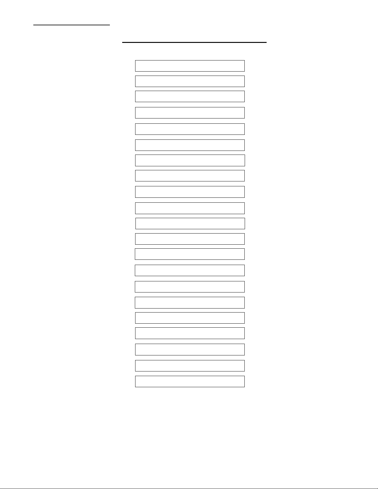
Main Troubleshooting Flow Chart
Dead Set 7-2
EEPROM Error Codes 7-3
System Control 7-4
Power Supply 7-5
Horizontal 7-6
Vertical 7-7
Tuner 7-8
Tuner Band Switching 7-9
Color 7-10
Video 7-11
Buttons 7-12
Infrared 7-12
OSD 7-13
Gemstar 7-14
F2PIP 7-15
Analog Comb 7-16
General Audio Problems 7-18
Distorted Audio 7-20
Stereo Seperation 7-20
No Stereo 7-21
Sound Logic 7-22
Page 7-1
Return To Main Flow Chart
Page 2
CTC203
TROUBLESHOOTING
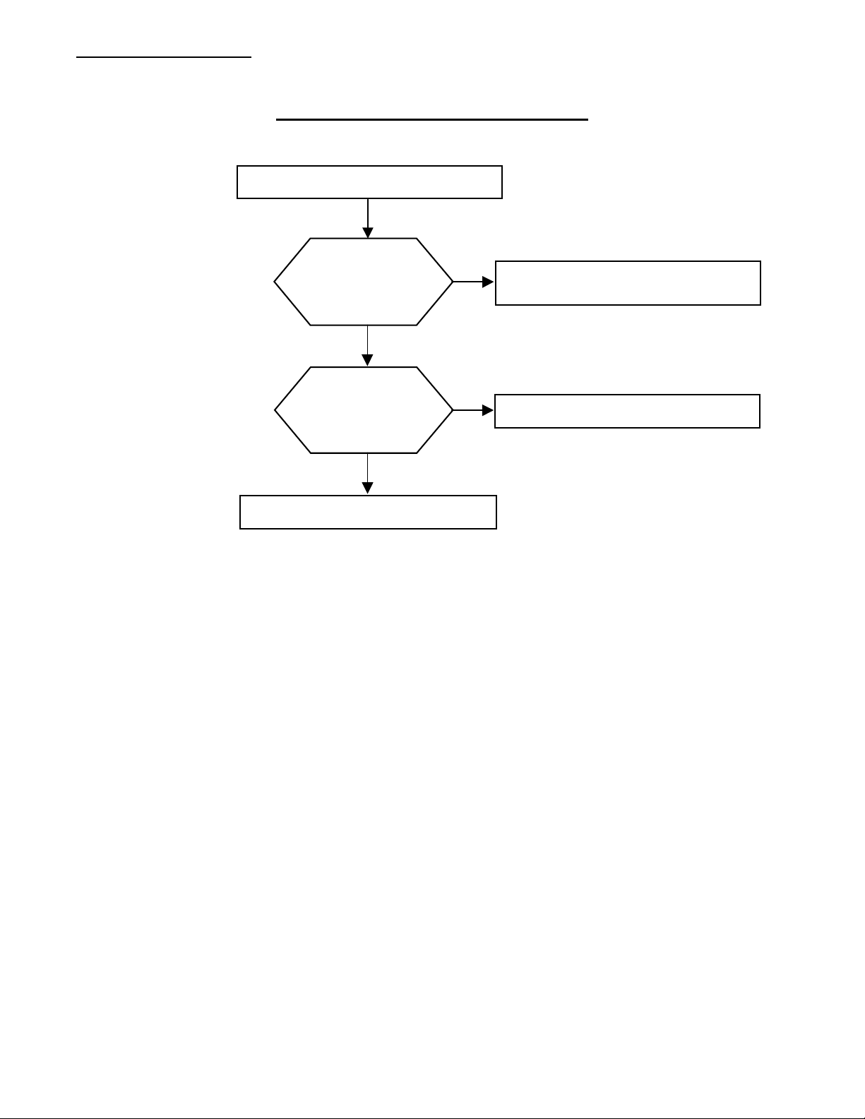
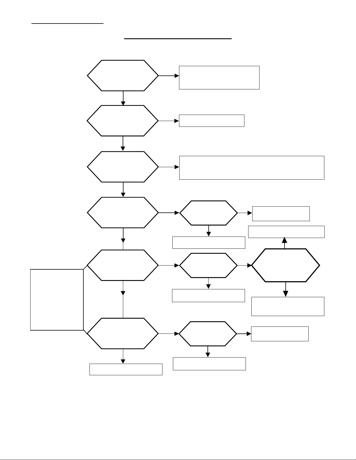
DEAD SET TROUBLESHOOTING
Set Will Not Turn On
Degauss Relay
Switching
ON/OFF?
NO
Microprocessor
U13101 Reset
Pin 51 = 5V?
YES
YES
Check EEPROM Error Codes
Using Chipper Check
Check System Control
NO
Check Power Supplies
Page 7-2
Return To Main Flow Chart
Page 3
CTC203
TROUBLESHOOTING
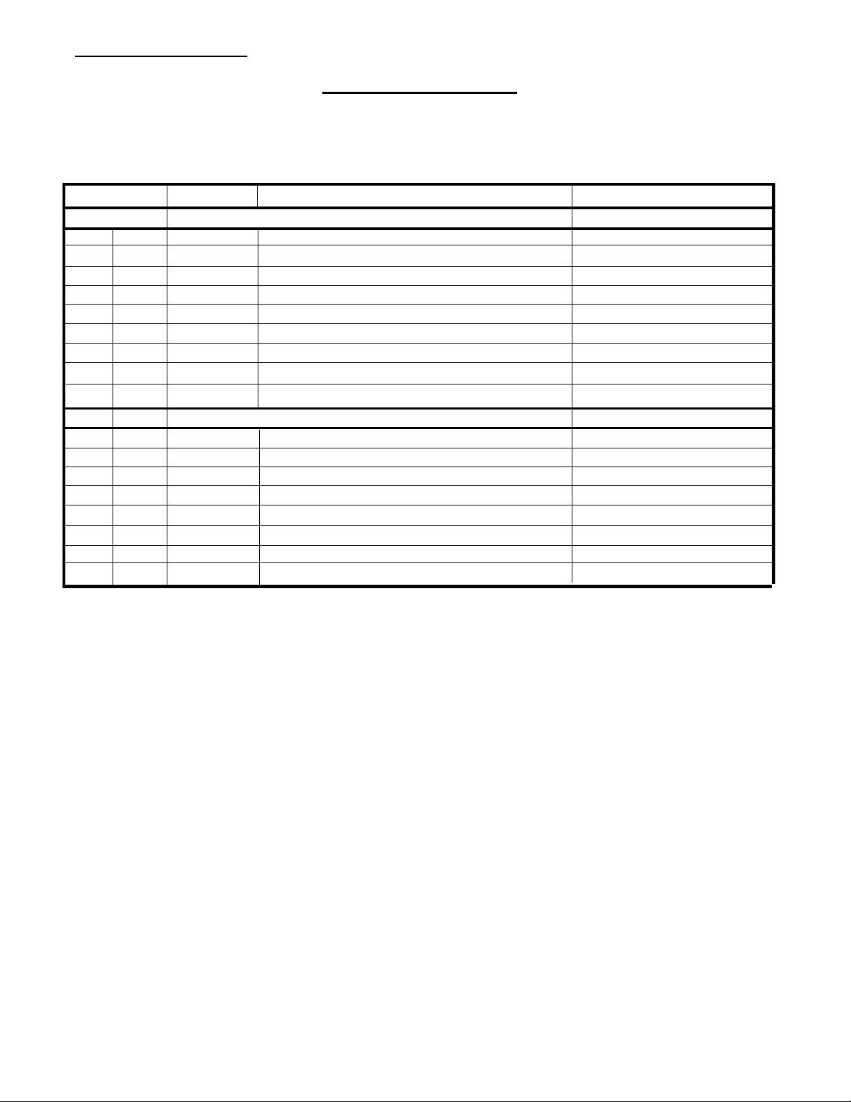
EEPROM Error Codes
Error code: Chassis: Error: Action
HEX DEC POWER CONTROL ERRORS
00 0 ALL No Errors
01 1 ALL 16V_STBY fault Check Power Supplies
03 3 ALL 12V_RUN fault Check Power Supplies
08 8 ALL T4chip XRP (X-ray protection) Check Power Supplies
09 9 ALL T4chip POR (power on reset) Check Horizontal
0A 10 w/ F2PIP F2PIP POR Check F2PIP
0B 11 ALL Stereo Decoder POR Check General Audio
10 16 ALL Run I2C bus latched Check System Control
12 18 ALL Standby I2C bus latched Check System Control
HEX DEC I
22 34 w/Gemstar Failure to get acknowledge from Gemstar module Check Gemstar
2C 44 w/ F2PIP F2PIP fault Check F2PIP
66 102 w/Gemstar Gemstar bus fault Check Gemstar
80 128 ALL Stereo Decoder fault Check General Audio
A0 160 EEPROM EEPROM bus fault Check System Control
BA 186 ALL T4chip fault Check System Control
C4 196 ALL Main Tuner PLL bus fault Check Tuner
C6 198 ALL Main Tuner DAC bus fault Check Tuner
2
C ACKNOWLEDGE ERRORS
Page 7-3
Return To Main Flow Chart
Page 4
CTC203
TROUBLESHOOTING
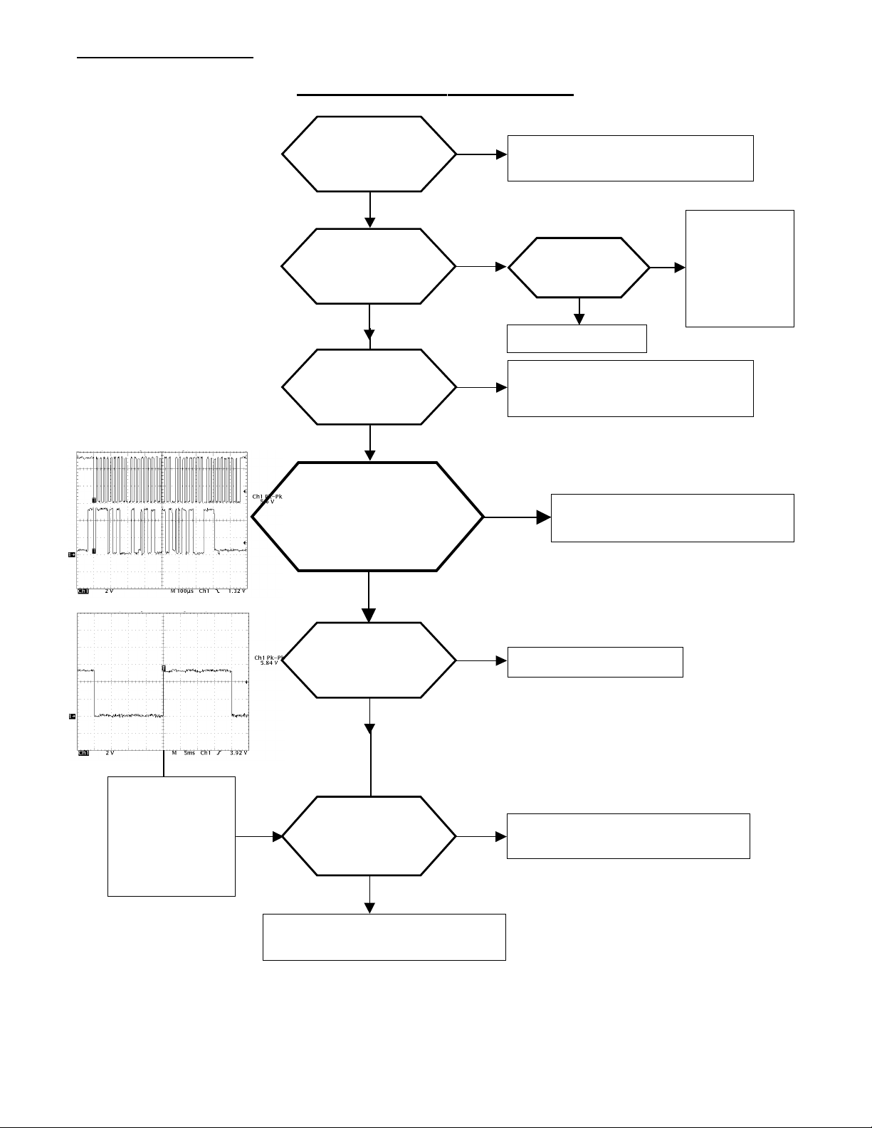
System Control Troubleshooting
Microprocessor
U13101
Pin 51 = 5V?
YES
EEPROM
U13102
Pin 8 = 5V?
YES
NO
NO
Check Micro Reset Circuit.
Q13501, Q13503, etc.
U13101
Pin 20 ~4.5V?
Replace Q13104
YES
NO
Check R13128,
R13181,Q13104.
U13101 Pin 20
should be High
Impedance. If
not replace.
Microprocessor
U13101
Pins 40,42 = 4MHz?
YES
Plug in AC. Check Bus
Activity on U13101 Pins
23,24. Do Transmissions
Stop after a few moments?
NO
YES
Microprocessor
U13101 KD1
Pin 5 = 5V Pulse?
YES
NO
NO
Replace 4MHz Crystal Y13101,
R13107,C13106,C13107
Check EEPROM and Power
Supplies
Check Power Supply
Note: Pin 5, Drive
Line, should have a
20ms pulse. If this
pulse is seen on a
sense line then a
button is closed.
Microprocessor
U13101 Sense Lines
Pins 6,7,8 = Steady
5V with No pulses?
YES
NO
Check EEPROM Error Codes
Using Chipper Check
Page 7-4
Check Front Panel for Stuck or
Shorted Button or Missing 5V.
Return To Main Flow Chart
Page 5
CTC203
TROUBLESHOOTING
Power Supply Troubleshooting
Raw B+
@TP14210
~ 150V ?
YES
+16V stanby
Cathode CR14108
~ 16V?
YES
NO
NO
Check F14201, R14202,
CR14201-CR14204
Check CR14108
If the Degaus
Relay is clicking
then the +12Vs
and +7.5Vs will
be ON only
momentarily at
turn ON.
RegB+ Cathode
CR14106
~ 130V?
YES
+5V stanby
U14103 Pin 3
~ 5.2V?
YES
+12V Switch
U14104 Pin 3
~ 12.2V?
YES
+7.5V Switch
U14150 Pin 3
~ 7.3V?
YES
NO
NO
NO
NO
Check RegB+ Circuit. R14116,U14101,U14102,
Q14102,Q14103,Q14106,Q14107,Q14101
U14103 Pin 1
~ 14.8V?
YES
NO
Check CR14110
Replace Q14104,Q14105
Replace U14103
U14104 Pin 1
~ 16V?
YES
NO
YES
U13101 Pin 19~5V
with Power Button
Pressed?
NO
Replace U14104
Troubleshoot System
Control
U14150 Pin 1
~ 10V?
YES
NO
Check R14151
Power Supplies OK
Replace U14150
Page 7-5
Return To Main Flow Chart
Page 6
CTC203
TROUBLESHOOTING
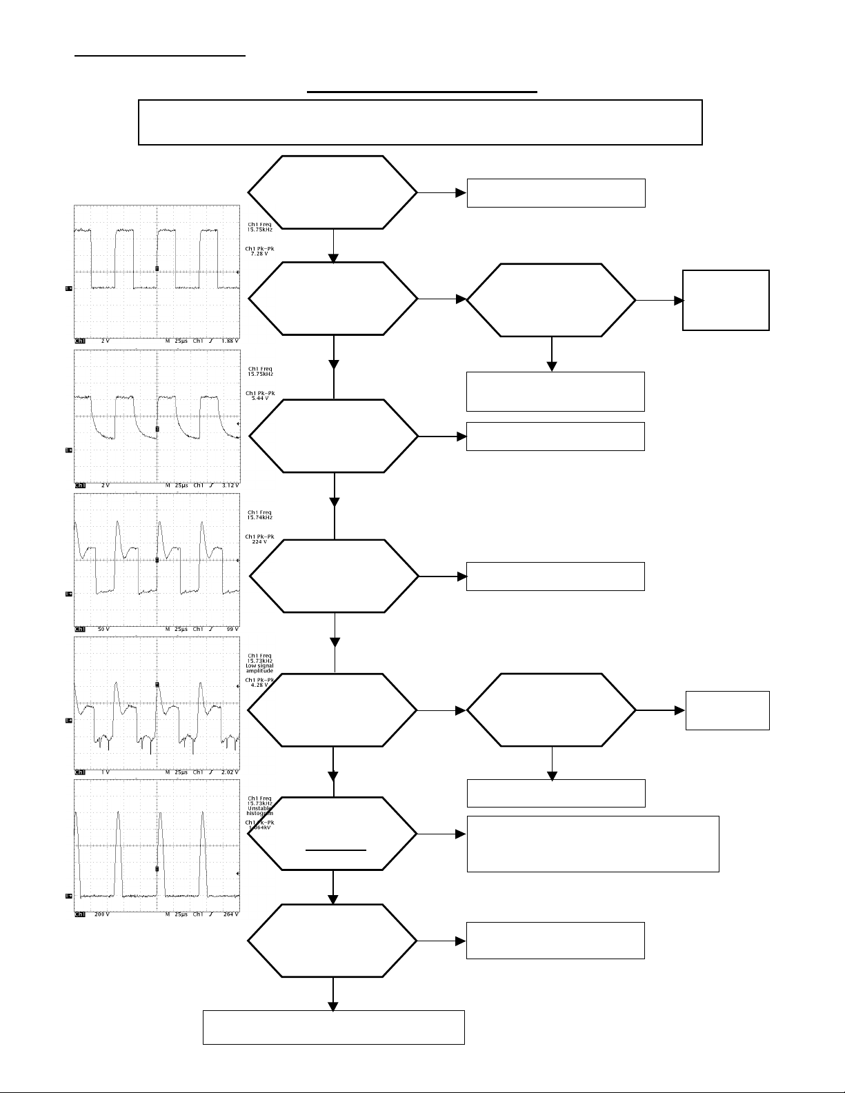
Horizontal Troubleshooting
NOTE:
If the Set is going into XRP shutdown the Degaus Relay will click
and the pulses below will only be present momentarily at turn ON
T4 Chip
U12101
Pin20 =7.6V?
YES
T4 Chip U12101
Pin 22 =7.2Vp-p
Square Wave?
YES
NO
NO
Check U14150
T4 Chip U12101
Bus Activity on
Pins 43, 44?
YES
NO
Replace U12101
(See Note at Top)
Q14302 Emitter
= 5.3Vp-p
Square Wave?
YES
NO
Replace Q14302
Troubleshoot
System
Control
Q14301Collector
= 224Vp-p ?
YES
Q14401 Base
~ 3.1Vp-p?
YES
Q14401
Collector
= 1060 Vp-p?
YES
EEPROM Code
indicates XRP
Fault?
YES
NO
NO
NO
NO
Replace Q14301
With Set OFF is
there Continuity
in T14301?
YES
NO
Check Base Components
Check Bad Q14401, Shorted or open
T14401, Bad Horizontal Yoke Winding.
Check C14403, CR14403 and RegB+.
Horizontal Test
Complete
Replace
T14301
Check XRP Circuitry Q14901, CR14902,
R14902, R14903, R14905
Page 7-6
Return To Main Flow Chart
Page 7
CTC203
TROUBLESHOOTING
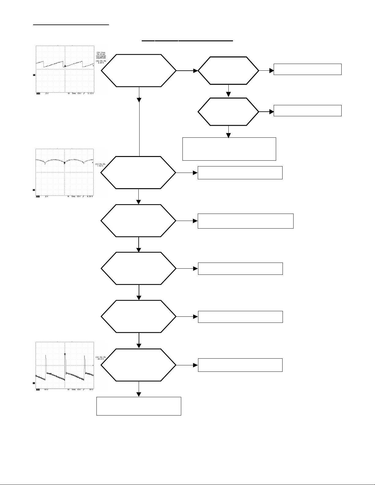
Vertical Troubleshooting
T4 Chip U12101
Pin 15 ~2.4V
Sawtooth ?
YES
U14501 Pin 1
~2V Parabola ?
YES
U14501
Pin 2 ~ 23V?
YES
NO
NO
NO
T4-Chip
U12101 Pin
26 =7.6V?
YES
T4-Chip
U12101 Pin
20 =7.6V?
YES
Reinitialize EEPROM Vertical
Settings. Replace U12101 if Reinit
doesn't work
NO
NO
Replace RN14501
Troubleshoot Power Supply
Check U14150
Check R14153
U14501
Pin 6 ~ 23V?
YES
NO
U14501
Pin 3 ~ 1.5V?
YES
U14501 Pin 5
~50V Vertical
Ramp?
YES
NO
NO
Check Connection P14501
and Choke Continuity
Check CR14501
Replace U14501
Replace U14501
Page 7-7
Return To Main Flow Chart
Page 8

CTC203
TROUBLESHOOTING
NOTE: If the GEMSTAR is set up to use a DSS or Cable Box the Tuner may be locked
to the input channel for that device. The OSD will still show a channel change but the
Channel DOES NOT change therefore the tuning voltages will NOT change
Check Supplies to Tuner.
+5,+9,+12,-12,+33
Tuner Troubleshooting
All Supplies
Present?
YES
NO
Troubleshoot Power Supplies
See Note at Top of page
Goto Band Switch
Troubleshooting
on next page.
Check U12101
Pin 5 and
components in
AGC Line.
Does Set Tune?
YES
Do All Bands
NO
Tune?
YES
Does AGC Voltage
Change when Input
NO
is Attenuated?
YES
Use Chipper Check to
Check Tuner alignment
and EEPROM Values
NO
Does OSD
Change?
YES
U17401 Pins18,19.
Is There Bus
Activity?
YES
U17401 Pins 5,6,7,8.
Are Voltages Close
To Voltage Chart?
YES
U17301 Pin 11.
Does Voltage
change with
Bands?
YES
Troubleshoot
NO
NO
See Note at Top of page
NO
NO
Control System
Troubleshoot
Control System
Replace U17401
Replace Q17402
Page 7-8
Does AGC Voltage
Change when Input
is Attenuated?
YES
NO
Troubleshoot Video
Replace U17301
Return To Main Flow Chart
Page 9

CTC203
TROUBLESHOOTING
Tuner Troubleshooting (continued)
Troubleshoot Band Switches
Check Supplies to Tuner.
+5,+9,+12,-12,+33
See Note at Top of previous page
U17401 Pins 5,6,7,8.
Are Voltages Close
To Voltage Chart?
YES
Q17404
Switching
Voltages Correct?
YES
NO
NO
Replace U17401
Replace Q17404
Q17402
Switching
Voltages Correct?
YES
NO
Set Tunes
Band 3?
YES
NO
Set Tunes
Either Band
NO
1 or 2?
YES
Check Diodes CR17105, CR17112,
CR17109, CR17110, CR17303.
Replace as needed
Replace Q17402
Replace CR17101, CR17114,
CR17102, CR17103, CR17301,
CR17304 & Q17101
Q17403
Switching
Voltages Correct?
YES
NO
Replace CR17106, CR17107,
CR17108, CR17111, CR17113,
CR17302 & Q17102.
Replace Q17403
Page 7-9
Return To Main Flow Chart
Page 10

CTC203
TROUBLESHOOTING
Color Troubleshooting
No Color
U12101 Pin 42
Color Burst >
200mV?
YES
U12101 Pin 40
Color Burst >
100mV?
YES
U12101 Pin 39
Color Killer
~3.5V?
YES
U12101 Pin 13
Chroma APC
~5.5V?
YES
NO
NO
NO
NO
Check Input Signal strength.
Troubleshoot Tuner if strong
signal is attached to input.
Troubleshoot Video Module
NOTE: Color Killer is active if Pin 39 ~1.5V
Check R12801, R12802, R12804 and
C12801. If components are good
Replace U12101
Check attached components and for
7.6VrA
U12101 Pin 41
Test Filter
~5.5V?
YES
Replace U12101
NO
Check attached components and for
7.6VrF
Page 7-10
Return To Main Flow Chart
Page 11

CTC203
TROUBLESHOOTING
Video Troubleshooting
No Video
U12101 Pin 42
~ 2Vp-p?
YES
U12101 Pin 38
~ 1Vp-p-?
YES
U12101 Pin 30,
31,32 ~ 2.5Vp-p
Video Signal?
YES
Video present at
collectors of
Q12701, Q12702,
Q12703?
YES
NO
NO
NO
NO
Check Input Signal strength.
Troubleshoot Tuner if strong
signal is attached to input.
Troubleshoot Video Module
(F2PIP or Analog Comb)
Replace U12101
Replace Faulty Transistors
Check that pins in connec-
tor are soldered properly.
12VrK Present at
bases of Q12701,
Q15102, Q15103?
YES
Video present at
collectors of
Q15101, Q15102,
Q15103?
YES
NO
NO
Check the CRT Screen
Control and that the
Filaments are glowing.
Troubleshoot 12V supply
Replace Faulty Transistors
Page 7-11
Return To Main Flow Chart
Page 12

CTC203
TROUBLESHOOTING
respond to either the Remote Control or Button Press.
Set does not respond to some
User Interface Troubleshooting
If a Button is shorted or stuck closed the set will not
button presses.
U13101Pin5
~ 20ms Square
Wave?
YES
NO
Troubleshoot System Control
U13101 Pin 6,7,8
= 5V?
YES
When Power, Volume Up, or Volume Down is pressed there should be ~20ms
low pulse on their respective sense line. If pulse is not present check for a
bad switch. If Channel Up, Channel Down or Menu is pressed their respec-
tive sense line should go Low for the duration of the button press. If not
check for a bad switch.
NO
Check 5V and R13113,
R13118, R13119.
Set does not respond to
Remote Control.
Set Responds to
all buttons?
YES
NO
Troubleshoot Buttons
5V at VCC Pin of
IR receiver?
YES
~5Vp-p Transmission at Output Pin
of IR receiver?
YES
NO
NO
Troubleshoot System Control
U13101 Pin 36.
Page 7-12
Troubleshoot Power Supply
Replace IR Receiver
Return To Main Flow Chart
Page 13

CTC203
TROUBLESHOOTING
Set does not have Channel
OSD Troubleshooting
Numbers or Menus
U13101Pin 35
Horizontal
Present?
YES
U14150 Pin 3 ~
1.5V?
YES
NO
NO
Check Q13301
Replace U14150
U13101 Pin 34
Vertical Present ?
YES
Press "Menu".
U13101Pin 26,
27,28 is OSD
Present?
YES
Press "Menu".
U12101Pin 34,
35, 36 is OSD
Present?
YES
NO
NO
NO
If Video is normal replace U12101.
If Video is missing Troubleshoot
Video
Check Pin 3 U14150, JC14105,
13320, R13314.
Replace U13101
Check components between
U13101 and U12101
Page 7-13
Return To Main Flow Chart
Page 14

CTC203
TROUBLESHOOTING
Tune set to a channel with valid GEMSTAR program information on the
Vertical Blankin Interval (VBI). Gemstar is auto-detected by the micro-
processor. Select the Main menu. If GEMSTAR has been detected there
displays "GUIDE
GEMSTAR Troubleshooting
will be a menu item "Guide Plus+ Menu".
Main Menu
PLUS+ Menu" ?
YES
NO
Module Cables
seated Properly
?
YES
+5.2V present
U26401 pins 12,
24, 31, 42, 51,
61, 65, 73?
YES
NO
NO
If item is not present check
the cable(s) to the GEMSTAR
module to make sure they are
seated properly. Select the
menu again, item will show up
if this was the problem.
Troubleshoot +5.2V network
and supply
GUIDE Menu is
present ?
YES
NO
4.03MHz OSC
on U26401 Pins
66,67?
YES
Pulsed Bus
activity on U26401
Pins 69, 70?
YES
Replace U26401
Vertical present on
U26405 pin 2 ?
YES
Vertical present on
U26401 pin 36 ?
NO
NO
NO
NO
Check for proper components
and that all parts are soldered.
Replace Y26401.
Check bus lines and compo-
nents and that all parts are
soldered.
Check U13101 pins 13,14.
Check line and components
back to J13103.
Troubleshoot Vertical.
Replace U26405
NEXT PAGE
Page 7-14
YES
Horizontal
present on
U26401 pin 39 ?
YES
NO
Check Q26403
Return To Main Flow Chart
Page 15

CTC203
TROUBLESHOOTING
GEMSTAR Troubleshooting (cotinued)
FROM PREVIOUS PAGE
U26401Reset pin
71 ~5.2V ?
YES
NO
Check components attached
to U26401pins 62,63. These
control the OSD dot clock.
RGB present
U26401 pins
48,49,50?
YES
NO
FSW present
U26401 pin 53 ?
YES
NO
Check line to J13103.
Troubleshoot System Control
Replace U26401
Replace U26401
Check Connector J13103
Troubleshoot Video
Valid Data
Stored in
GUIDE ?
YES
NO
Make sure set is tuned to GEMSTAR data provider. Select
"MainMenu", select "GUIDE Plus+ Menu", select
"GUIDE Plus+ Setup". On the Remote Control Press
"Go Back" and then "TV". This will bring up the Factory
ROM Test
Passed?
YES
RAM Test
Passed?
YES
VBI Test
Passed?
YES
Check Owners manual on GIUDE Plus+ Setup
procedures.
Diagnostic Screen.
NO
NO
NO
Tuned to Non-VBI channel?
Check Q26405 composite
Video also Q26404,Q26408
which supply sync during "set
Replace U26402
Replace U26403
off" downloads.
Page 7-15
Return To Main Flow Chart
Page 16

CTC203
TROUBLESHOOTING
EEPROM Error indicates a
F2PIP Troubleshooting
F2PIP error.
Does set turn
ON?
YES
Set has a Main
Picture?
YES
NO
NO
Check Y18100, 14.318MHz
crystal. Should be within 1Khz
of nominal to guarantee
proper operation
Check 3.3V supply.
Check Data and Clock Lines.
Check main Video Signal path.
If above is good replace U18100
PIP Turns ON? Check for proper Vert. &
NO
YES
PIP Picture
Visible?
YES
NO
PIP Picture
Distorted ?
YES
NO
Use Chipper Check to check
PIP Alignments.
Horz. Sync at U18100 Pin 24
Check PIP contrast and
Brightness alignments.
Check PIP signal Path
PIP Normal
Page 7-16
Return To Main Flow Chart
Page 17

CTC203
TROUBLESHOOTING
Connect a signal generator to the Tuner Input and to
Analog Comb Troubleshooting
the Video Input Jack. Check 5V and 12V supplies.
U26903
Pin 6 = TV
Video Signal
YES
U26903
Pin 3 = Input
Video Signal
YES
NO
NO
Troubleshoot Video Signal
Check R11406, C11403,
R26921
Luma
U26903 Pin 4
0V =TV Video
5.1V = Input Video
YES
U26903 Pin 8.
Signal can be
switched between TV
Video and Input
Video?
YES
Luma & Chroma
present at Pins 3
& 5 on FL2601
YES
Chroma present at
Pin 8 U26902
NO
NO
NO
NO
Check Q26903 and insure that
switching voltage is present
from U13101
Replace U26903
Replace FL2601
Replace U26902
Chroma
YES
Luma present at
Pin 6 J26901
YES
Analog Comb OK
NO
Page 7-17
Luma present at
Pin 8 U26901
YES
Replace Q26901
NO
Replace
U26901
Return To Main Flow Chart
Page 18

CTC203
TROUBLESHOOTING
Connect a generator to the set. Adjsut "Sound Processor" Menu to "Speak-
ers ON", Fixed Level Mode OFF", "Sound Logic OFF".
Sound Quick Checks:
1. Check that Speaker's plug is seated properly.
2. Check that the "Speakers" are turned ON & "Fixed Level Mode"is OFF
3. Check that Balance is Centered.
4. Check if there is audio present at Audio Output Jacks to isolate problem.
General Audio Troubleshooting
EEPROM Error
code indicates Audio
Problem.
Check menu items again. Send
Does set turn
ON?
YES
Wide Band
Audio present at
Pin 17 U11601 ?
YES
U11601 Pin 39,
40 Audio
ABSENT ?
YES
NO
NO
NO
Volume Up Command.
U11601 Pin 22
Vcc~ 9.4V ?
NO
Check 9V regulator Q11603.
Check U11601 Bus lines
Pins 9,10 .
Check C11601, Pin 6 U12101
Check Q11603
YES
U11601 Pin 12, 13,
17, 39, 40 Bias
Voltage~ 4.1V ?
YES
U11601 Pin 12,
13, Audio
Present ?
YES
Go To Next Page
NO
NO
Replace U11601
Replace U11601
Page 7-18
Return To Main Flow Chart
Page 19

CTC203
TROUBLESHOOTING
Set Volume To Max
Genearl Audio Troubleshooting (continued)
U11601 Pins 7, 8
Audio Present?
YES
U11602 Pins 1, 7
Audio Present?
YES
NO
NO
U11601 Pins 1, 8
Bias ~4.1V?
YES
Components
on U11601
Pins 1-4,7, 8
Correct?
YES
Replace U11601
U11602 Pin 8
~+8V and Pin 4
~ -8V ?
YES
Components
on U11602
Correct?
YES
NO
NO
NO
NO
Replace U11601
Replace with correct
components
Troubleshoot Power
Supplies
Replace with correct
components
U11900/11901
Pin 2 Audio
Present?
YES
NO
Check Connector J11901
Replace U11602
+16V Supply
U11900/11901
U11900/11901
YES
( 71mVrms )?
Page 7-19
present ?
YES
Pin 3
>7V ?
YES
Pin 4 Audio
Present
NO
NO
NO
Troubleshoot Power
Supplies
Check Q11901, C11909,
U13101 Pin 2
Replace U11900/11901
Return To Main Flow Chart
Page 20

CTC203
TROUBLESHOOTING
Use a standard 1kHz or 3kHz Sine Wave as an input to the Audio System.
Scope Audio at HiFi or Speaker Outputs (whichever is failing) to determine
if distortion is visible. Move back along Audio signal path to determine
where distortion begins. If point of origin cannot be determined check the
Check for electrolytics installed backwards or solder shorts around U11601.
Anything that can cause shorts or improper bias on the IC pins. Check for
Check values of R11704/11706. Excessive gain in Expanded Stereo can cause
Loop IN (U11601 Pins 41,41) to be overdriven. This can cause distortion in
Audio Troubleshooting (Distortion)
things below.
open traces or missing jumper wires.
All Modes.
Check voltages on Vcc pins at the Audio ICs as well as the power network
that supplies power to the audio circuit for proper voltage levels.
Check that the Pins of all Audio ICs are soldered properly. Unsoldered pins
can cause overheating and shutdown in the output devices.
If Speaker output is distorted but HiFi outputs are not then the problem is
probably in the U11900/11901 circuit area.
Check that coupling capacitors are loaded properly. Check for shorts
around U11900/U11901 and that the devices are not partially MUTED.
No Stereo Seperation
Problems with stereo seperation are mostly due to wrong, missing or back-
ward parts around U11601. Specifically C11605, C11610 and other parts
connected to pins 16, 18, 23, 24, 28, 29, 30 and 34. this can cause failure of
one of the alignments.
Page 7-20
Return To Main Flow Chart
Page 21

CTC203
TROUBLESHOOTING
Tune to a channel with known good strereo. Set SOUND PROCESSOR
mode to STEREO. Insure set is working with Mono audio signal.
Audio Troubleshooting (No Stereo)
U11601 not locked to strereo pilot or pilot
Set OSD says
STEREO?
YES
Stereo signal
@ U11601 Pins
23, 24, 31&32?
YES
U11601 Pins
39,40 Stereo
Present?
YES
NO
NO
NO
level to low. Check components at pins 14,
15, & 16 for correct values and proper
Replace U11601
Use Chipper Check to view Stereo alignment
values. Values near one end of the alignment
range may indicate wrong or missing compo-
nents. Noisy or improperly aligned SIF or
poorly aligned stereo alingment. Attempt to
installation.
realign.
U11601 Pins
14,15,16,19,28,29,30
&34 bias
correct?
YES
U11601 Pins 7,
8 stereo signal
both channels?
YES
U11602 Pins 1
& 7stereo
signal both
channels?
YES
U11900/11901
Pin 2, stereo
signal both
channels?
YES
NO
NO
NO
NO
Check components at dbx pins for correct
values and proper installation. If compo-
nents are correct Replace U11601
Replace U11601
Replace U11602
Replace device without signal
Check connector J11901, P11901
and speakers
Page 7-21
Return To Main Flow Chart
Page 22

CTC203
TROUBLESHOOTING
Tune to a channel with strong MONO signal. Connect a DC
Audio Troubleshooting (Sound Logic)
voltmeter to cathode of CR11503.
Voltmeter
reading ~4V ?
YES
NO
Remove Audio input
Voltmeter
reading <100mV
?
YES
U13101 Pin 37
Voltage same as
@ CR11503 ?
YES
NO
NO
Sound Logic OK
Check components around U11501 for
correct values and proper installation. In-
sure that there is a strong WBAudio Signal
at U11601 Pin 17.
Check +12V and -12V supplies. Check for
missing parts, wrong values or solder prob-
lems. Replace U11501
Check components in Sound logic line be-
tween U13101 pin 37 and CR11503
Page 7-22
Return To Main Flow Chart
 Loading...