


SAFETY PRECASAFETY PRECA
SAFETY PRECA
SAFETY PRECASAFETY PRECA
SERSER
VICE VICE
SER
SERSER
Only qualified service technicians who are familiar with safety checks
and guidelines should perform service work. Before replacing parts,
disconnect power source to protect electrostatically sensitive parts. Do
not attempt to modify any circuit unless so recommended by the
manufacturer. When servicing the receiver, use an isolation transformer
between the line cord and power receptacle.
SERSER
SER
SERSER
Use EXTREME CAUTION when servicing the high voltage circuits. To
discharge static high voltage, connect a 10K ohms resistor in series with a
test lead between the receiver ground and CRT anode lead. DO NOT lift
the CRT by the neck. Always wear shatterproof goggles when handling
the CRT to protect eyes in case of implosion.
X-RAX-RA
X-RA
X-RAX-RA
Be aware of the instructions and procedures covering X-ray radiation. In
solid-state receivers and monitors, the CRT is the only potential source of
X-rays. Keep an accurate high voltage meter available at all times. Check
meter calibration periodically. Whenever servicing a receiver, check the
high voltage at various brightness levels to be sure it is regulating
properly. Keep high voltage at rated value, NO HIGHER. Excessive high
voltage may cause X-ray radiation or failure of associated components.
DO NOT depend on protection circuits to keep voltage at rated value.
When troubleshooting a receiver with excessive high voltage, avoid close
contact with the CRT. DO NOT operate the receiver longer than
necessary. To locate the cause of excessive high voltage, use a variable
AC transformer to regulate voltage. In present receivers, many electrical
and mechanical components have safety related characteristics which are
not detectable by visual inspection. Such components are identified by a
# on both the schematic and the parts list. For SAFETY, use only
equivalent replacement parts when replacing these components.
GENERAL GUIDELINESGENERAL GUIDELINES
GENERAL GUIDELINES
GENERAL GUIDELINESGENERAL GUIDELINES
Perform a final SAFETY CHECK before returning receiver to customer.
Check repaired area for poorly soldered connections, and check entire
circuit board for solder splashes. Check board wiring for pinched wires or
wires contacting any high wattage resistors. Check that all control knobs,
shields, covers, grounds, and mounting hardware have been replaced. Be
sure to replace all insulators and restore proper lead dress.
WARNINGWARNING
VICE
WARNING
VICE VICE
WARNINGWARNING
VICING VICING
VICING
VICING VICING
Y RADIAY RADIA
Y RADIA
Y RADIAY RADIA
THE HIGH THE HIGH
THE HIGH
THE HIGH THE HIGH
TION AND HIGH TION AND HIGH
TION AND HIGH
TION AND HIGH TION AND HIGH
VV
OLOL
V
OL
VV
OLOL
TT
AA
GE AND CRGE AND CR
T
A
GE AND CR
TT
AA
GE AND CRGE AND CR
VV
OLOL
TT
V
OL
T
VV
OLOL
TT
TT
T
TT
AA
GE LIMITSGE LIMITS
A
GE LIMITS
AA
GE LIMITSGE LIMITS
UTIONSUTIONS
UTIONS
UTIONSUTIONS
SAFETY CHECKS — FIRE AND SHOCK HAZARDSAFETY CHECKS — FIRE AND SHOCK HAZARD
SAFETY CHECKS — FIRE AND SHOCK HAZARD
SAFETY CHECKS — FIRE AND SHOCK HAZARDSAFETY CHECKS — FIRE AND SHOCK HAZARD
Cold LeakaCold Leaka
Cold Leaka
Cold LeakaCold Leaka
Unplug the AC cord, connect a jumper across the plug prongs, and turn
the power switch on (if applicable). Use an ohmmeter to measure the
resistance between the jumped AC plug and any exposed metal cabinet
parts such as antenna screw heads, control shafts, or handle brackets.
Exposed metal parts with a return path should measure between 1M
ohms and 5.2M ohms. Parts without a return path must measure infinity.
Hot LeakaHot Leaka
Hot Leaka
Hot LeakaHot Leaka
Plug the AC cord directly into an AC outlet. DO NOT use an isolation
transformer. Use a 1500 ohms, 10W resistor in parallel with a .15µF
capacitor to connect between any exposed metal parts on the receiver and
a good earth ground. (See figure below.) Use an AC voltmeter with at
least 5000 ohms per volt sensitivity to measure the voltage across the
resistor. Check all exposed metal parts and measure voltage at each point.
Voltage measurements should not exceed .75VAC, 500µA. Any value
exceeding this limit constitutes a potential shock hazard and must be
corrected. If the AC plug is not polarized, reverse the AC plug and repeat
exposed metal part voltage measurement at each point.
gg
e Chece Chec
e Chec
e Chece Chec
ks fks f
ks f
ks fks f
g
gg
gg
e Current Chece Current Chec
g
e Current Chec
gg
e Current Chece Current Chec
or Receiveror Receiver
or Receiver
or Receiveror Receiver
kk
k
kk
s with Isolated Grs with Isolated Gr
s with Isolated Gr
s with Isolated Grs with Isolated Gr
oundound
ound
oundound
SET 4544SET 4544
SET 4544SET 4544
SET 4544
High Voltage Shutdown Test .................. 1
IC Functions ........................................... 1
Important Parts Information ................... 2
Miscellaneous Adjustments .................... 1
New Circuit ............................................ 1
Parts List ............................................. 7, 8
Placement Chart ................................. 5, 6
Safety Precautions .................................. 1
Schematic Component Location ............ 6
Schematic Notes ..................................... 2
Schematics
Test Equipment....................................... 2
Tuner Information .................................. 1
INDEXINDEX
INDEX
INDEXINDEX
Audio ............................................... 3
CRT ................................................. 3
PIP ................................................... 4
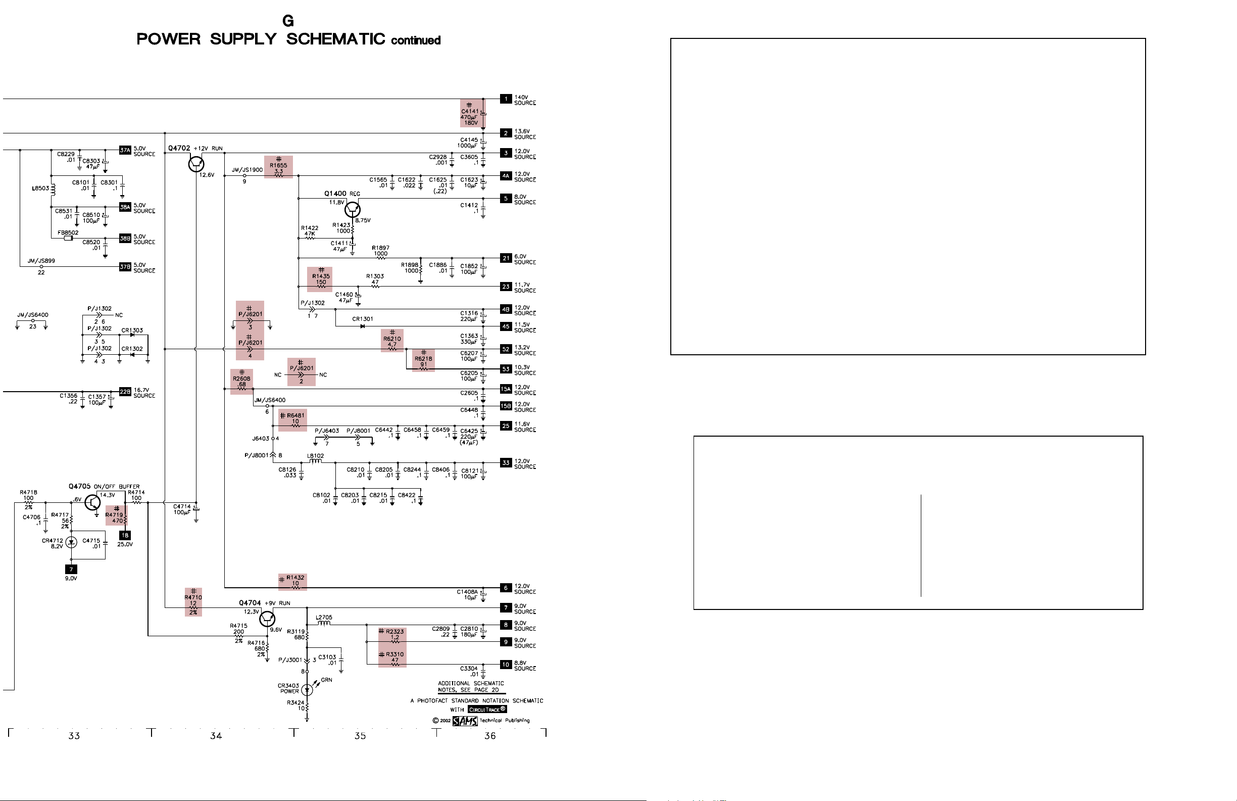
Power Supply .................................. 2
Surround Audio ............................... 5
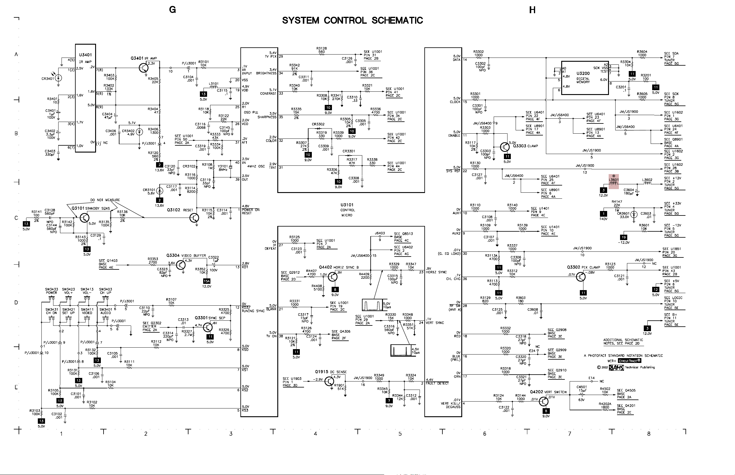
System Control ................................ 1
Television ........................................ 2
Tuner ............................................... 5
Video Switching/Digital Comb ....... 4
Technical Service Data
PRPR
OSCANOSCAN
PR
OSCAN
PRPR
OSCANOSCAN
Model PS27152FX1 (Chassis CTC169CE5)Model PS27152FX1 (Chassis CTC169CE5)
Model PS27152FX1 (Chassis CTC169CE5)
Model PS27152FX1 (Chassis CTC169CE5)Model PS27152FX1 (Chassis CTC169CE5)
Representative Model
ff
or seror ser
f
or ser
ff
or seror ser
Essential coEssential co
Essential co
Essential coEssential co
vicing a televicing a tele
vicing a tele
vicing a televicing a tele
ScSc
hematicshematics
•
Sc
hematics
ScSc
hematicshematics
veravera
gg
vera
veravera
vision receivervision receiver
vision receiver
vision receivervision receiver
ee
g
e
gg
ee
......
...
......
4544
HIGH HIGH
VV
OLOL
TT
AA
HIGH
V
HIGH HIGH
VV
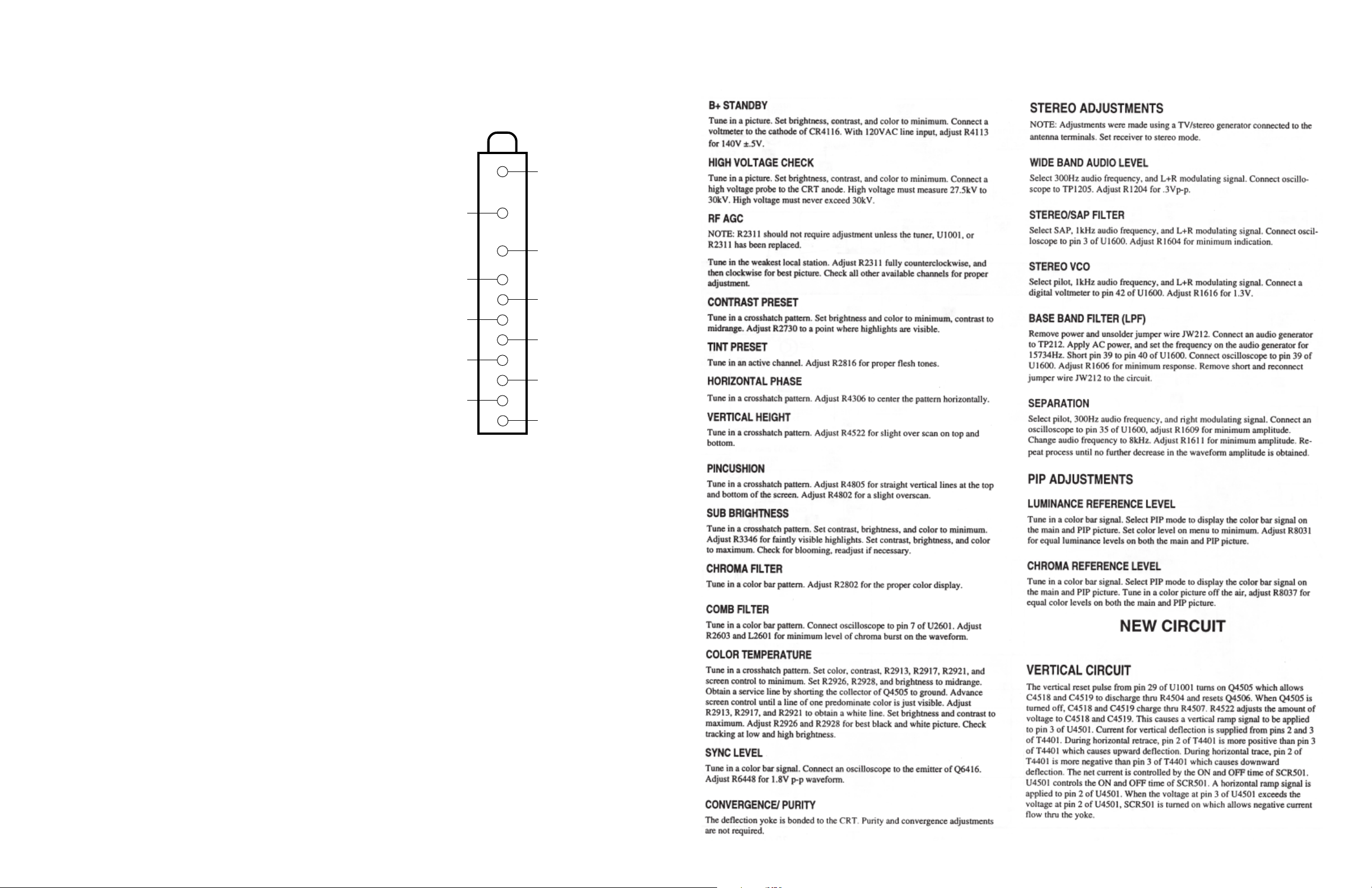
Apply 120VAC to set, turn set on, and adjust brightness and contrast to maximum. Short
XRP-1 to XRP-2. The set should shut down and then cycle on and off. If the set does not
shut down and then cycle on and off, the shutdown circuoit requires repair. To resume normal
operation remove the short from XRP-1 to XRP-2.
The listing of any available replacement part herein in no case constitutes a recommendation, warranty, or guarantee by
SAMS Technical Publishing as to the quality and suitability of such replacement part. The numbers of the listed parts have
been compiled from information furnished to SAMS Technical Publishing by the manufacturers of the specific type of
replacement part listed.
Reproduction or use, without express permission, of editorial or pictorial content, in any manner, is prohibited. No patent
liability is assumed with respect to the use of the information contained herein.
© 2002
5436 West 78th Street
Indianapolis, IN 46268-4149
Printed in the United States of America 5 4 3 2 1
PP
aa
gg
e 1e 1
a
g
e 1
aa
gg
e 1e 1
SET 4544 SET 4544
SET 4544
SET 4544 SET 4544
P
PP
GE SHUTDOGE SHUTDO
OL
T
A
GE SHUTDO
OLOL
TT
AA
GE SHUTDOGE SHUTDO
WN WN
TESTTEST
WN
TEST
WN WN
TESTTEST
02PF01843
UPC
HERE
4544
MODELPS27152FX1 (CHASSIS CTC169CE5)MODELPS27152FX1 (CHASSIS CTC169CE5)
MODELPS27152FX1 (CHASSIS CTC169CE5)MODELPS27152FX1 (CHASSIS CTC169CE5)
MODELPS27152FX1 (CHASSIS CTC169CE5)
OSCANOSCAN
OSCANOSCAN
OSCAN
PRPR
PRPR
PR
For Supplier AdFor Supplier Ad
For Supplier Ad
For Supplier AdFor Supplier Ad
See PHOSee PHO
See PHO
See PHOSee PHO
TT
T
TT
OFOF
OF
OFOF
AA
CT AnnCT Ann
A
CT Ann
AA
CT AnnCT Ann
dress,dress,
dress,
dress,dress,
ual Indeual Inde
ual Inde
ual Indeual Inde
xx
x
xx
Component locationsComponent locations
•
Component locations
Component locationsComponent locations
PP
arar
ts listts list
•
P
ar
ts list
PP
arar
ts listts list
Coverage includes these additional models and chassis:
ModelsModels
Models
ModelsModels
PS27152JX1 CTC169CE5
PS27153FX1 CTC169CH5
PS27153JX1 CTC169CH5
FEBRFEBR
UU
ARAR
Y Y
FEBR
FEBRFEBR
U
2002 SET 4544 2002 SET 4544
AR
Y
2002 SET 4544
UU
ARAR
Y Y
2002 SET 4544 2002 SET 4544
ChassisChassis
Chassis
ChassisChassis
4544
PP
aa
gg
e 1e 1
g
e 1
gg
e 1e 1
SET 4544 SET 4544
SET 4544
SET 4544 SET 4544
P
a
PP
aa
TUNER INFORMATION
TUNER TUNER
TUNER
TUNER TUNER
PinPin
Pin
PinPin
1 (AGC) 5.4V 4.1V 7.9V
2 (+12V) 12.0V 12.0V 12.0V
3 (IF) 11.7V 11.6V 11.7V
4 (+33V) 33.0V 33.0V 33.0V
5 (-12.0V) -12.0V -12.0V -12.0V
6 (+5V) 5.0V 5.0V 5.0V
7 (SDA) 5.0V 5.0V 5.0V
8 (SCK) 5.0V 5.0V 5.0V
9 (NC) 0V 0V 0V
10 (LOGIC) 0V 0V 0V
11 (B+) 12.0V 12.0V 12.0V
Note: VHF Low Band voltages taken on channel 2.
VHF High Band voltages taken on channel 7.
UHF Band voltages taken on channel 14
VHF LoVHF Lo
VHF Lo
VHF LoVHF Lo
VV
OLOL
V
OL
VV
OLOL
w Bandw Band
w Band
w Bandw Band
TT
AA
GE CHARGE CHAR
T
A
GE CHAR
TT
AA
GE CHARGE CHAR
VHF High BandVHF High Band
VHF High Band
VHF High BandVHF High Band
TT
T
TT
UHF BandUHF Band
UHF Band
UHF BandUHF Band
TUNER TUNER
TUNER
TUNER TUNER
(2)
(4)
(6)
(8)
(10)
TERMINAL GUIDETERMINAL GUIDE
TERMINAL GUIDE
TERMINAL GUIDETERMINAL GUIDE
(1)
t
t
(3)
t
t
(5)
t
t
(7)
t
t
(9)
t
t
MISCELLANEOUS ADJUSTMENTS
t
(11)

SET 4544 PSET 4544 P
SET 4544 P
SET 4544 PSET 4544 P
aa
gg
e 1e 1
a
g
e 1
aa
gg
e 1e 1
PR
PRPR
PRPR
OSCAN MODEL PS27152FX1 (CHASSIS CTC169CE5)
OSCAN MODEL PS27152FX1 (CHASSIS CTC169CE5)OSCAN MODEL PS27152FX1 (CHASSIS CTC169CE5)
OSCAN MODEL PS27152FX1 (CHASSIS CTC169CE5)OSCAN MODEL PS27152FX1 (CHASSIS CTC169CE5)
SET 4544 PSET 4544 P
SET 4544 P
SET 4544 PSET 4544 P
aa
gg
e 1e 1
a
g
e 1
aa
gg
e 1e 1

PP
aa
gg
e 2e 2
a
g
e 2
aa
gg
e 2e 2
SET 4544 SET 4544
SET 4544
SET 4544 SET 4544
P
PP

SET 4544 PSET 4544 P
SET 4544 P
SET 4544 PSET 4544 P
aa
gg
e 2e 2
a
g
e 2
aa
gg
e 2e 2

PP
aa
gg
e 2e 2
a
g
e 2
aa
gg
e 2e 2
SET 4544 SET 4544
SET 4544
SET 4544 SET 4544
P
PP
ImporImpor
tant Ptant P
arar
ts Infts Inf
Impor
tant P
ImporImpor
ν The parts listed here are those not usually available from a well-stocked supply cabinet or bin.
ν Where items may be replaced with equivalent parts, several alternates are shown from participating vendors.
ν On the parts lists, safety items are marked with a
these items.
ν When ordering parts, state the model number, part number, and description.
ar
tant Ptant P
arar
# #
# to remind you that only exact replacements are recommended for
# #
ts Inf
ts Infts Inf
ormationormation
ormation
ormationormation
Obtaining PObtaining P
Obtaining P
Obtaining PObtaining P
Many of these parts are available from your local Sams authorized distributor or the manufacturer of the equipment. Call
Sams for the name of your nearest distributor:
arar
ar
arar
tsts
ts
tsts
800-428-7267
Or consult the Sams
Information on test equipment and replacement parts is listed in these pages for the following participating vendors.
Consult the Sams
ν NTE Electronics, Inc. (NTE)
Test equipment listed by participating manufacturer illustrates typical or equivalent equipment used by Sams engineers to obtain
measurements. This equipment is compatible with most types used by field service technicians.
Annual Index
Annual Index
for the address of the original equipment manufacturer.
PP
arar
ticipating ticipating
P
ar
ticipating
PP
arar
ticipating ticipating
for their current address.
TEST EQTEST EQ
TEST EQ
TEST EQTEST EQ
VV
endorendor
endor
endorendor
ss
s
ss
V
VV
ν Sencore, Inc.
UIPMENTUIPMENT
UIPMENT
UIPMENTUIPMENT
PR
PRPR
PRPR
OSCAN MODEL PS27152FX1 (CHASSIS CTC169CE5)
OSCAN MODEL PS27152FX1 (CHASSIS CTC169CE5)OSCAN MODEL PS27152FX1 (CHASSIS CTC169CE5)
OSCAN MODEL PS27152FX1 (CHASSIS CTC169CE5)OSCAN MODEL PS27152FX1 (CHASSIS CTC169CE5)
EquipmentEquipment
Equipment
EquipmentEquipment
Oscilloscope SC3100
Generators
RGB CM2125
Multiburst Signal VG91
Color Bar VG91
TV Stereo VG91
Digital VOM SC3100
Frequency Meter SC3100
Hi-Voltage Probe HP200
Accessory Probes TP212
Sencore No.Sencore No.
Sencore No.
Sencore No.Sencore No.
EquipmentEquipment
Equipment
EquipmentEquipment
Isolation Transformer PR570
Capacitance Analyzer LC102
CRT Analyzer CR7000
AC Leakage Tester PR570
Inductance Analyzer LC102
Flyback Yoke Tester TVA92
Field Strength Meter SL753
Transistor Tester TF46
Horizontal Analyzer HA-2500
Video Analyzer VG91, TVA92
Sencore No.Sencore No.
Sencore No.
Sencore No.Sencore No.
SET 4544 PSET 4544 P
SET 4544 P
SET 4544 PSET 4544 P
aa
gg
e 2e 2
a
g
e 2
aa
gg
e 2e 2

PP
aa
gg
e 3e 3
a
g
e 3
aa
gg
e 3e 3
SET 4544 SET 4544
SET 4544
SET 4544 SET 4544
P
PP

SET 4544 PSET 4544 P
SET 4544 P
SET 4544 PSET 4544 P
aa
gg
e 3e 3
a
g
e 3
aa
gg
e 3e 3

PP
aa
gg
e 3e 3
a
g
e 3
aa
gg
e 3e 3
SET 4544 SET 4544
SET 4544
SET 4544 SET 4544
SET 4544 PSET 4544 P
SET 4544 P
SET 4544 PSET 4544 P
aa
gg
e 3e 3
a
g
e 3
aa
gg
e 3e 3
P
PP

PR
PRPR
PRPR
OSCAN MODEL PS27152FX1 (CHASSIS CTC169CE5)
OSCAN MODEL PS27152FX1 (CHASSIS CTC169CE5)OSCAN MODEL PS27152FX1 (CHASSIS CTC169CE5)
OSCAN MODEL PS27152FX1 (CHASSIS CTC169CE5)OSCAN MODEL PS27152FX1 (CHASSIS CTC169CE5)
SET 4544 PSET 4544 P
SET 4544 P
SET 4544 PSET 4544 P
aa
gg
e 3e 3
a
g
e 3
aa
gg
e 3e 3

PP
aa
gg
e 4 SET 4544e 4 SET 4544
P
a
g
e 4 SET 4544
PP
aa
gg
e 4 SET 4544e 4 SET 4544

SET 4544 PSET 4544 P
SET 4544 P
SET 4544 PSET 4544 P
aa
gg
e 4e 4
a
g
e 4
aa
gg
e 4e 4

PP
aa
gg
e 4e 4
a
g
e 4
aa
gg
e 4e 4
SET 4544 SET 4544
SET 4544
SET 4544 SET 4544
P
PP

PR
PRPR
PRPR
OSCAN MODEL PS27152FX1 (CHASSIS CTC169CE5)
OSCAN MODEL PS27152FX1 (CHASSIS CTC169CE5)OSCAN MODEL PS27152FX1 (CHASSIS CTC169CE5)
OSCAN MODEL PS27152FX1 (CHASSIS CTC169CE5)OSCAN MODEL PS27152FX1 (CHASSIS CTC169CE5)
SET 4544 PSET 4544 P
SET 4544 P
SET 4544 PSET 4544 P
aa
gg
e 4e 4
a
g
e 4
aa
gg
e 4e 4

PP
aa
gg
e 5e 5
a
g
e 5
aa
gg
e 5e 5
SET 4544 SET 4544
SET 4544
SET 4544 SET 4544
P
PP

SET 4544 PSET 4544 P
SET 4544 P
SET 4544 PSET 4544 P
aa
gg
e 5e 5
a
g
e 5
aa
gg
e 5e 5

PP
aa
gg
e 5e 5
a
g
e 5
aa
gg
e 5e 5
SET 4544 SET 4544
SET 4544
SET 4544 SET 4544
SET 4544 PSET 4544 P
SET 4544 P
SET 4544 PSET 4544 P
aa
gg
e 5e 5
a
g
e 5
aa
gg
e 5e 5
P
PP

PR
PRPR
PRPR
OSCAN MODEL PS27152FX1 (CHASSIS CTC169CE5)
OSCAN MODEL PS27152FX1 (CHASSIS CTC169CE5)OSCAN MODEL PS27152FX1 (CHASSIS CTC169CE5)
OSCAN MODEL PS27152FX1 (CHASSIS CTC169CE5)OSCAN MODEL PS27152FX1 (CHASSIS CTC169CE5)
SET 4544 PSET 4544 P
SET 4544 P
SET 4544 PSET 4544 P
aa
gg
e 5e 5
a
g
e 5
aa
gg
e 5e 5

PP
aa
gg
e 6e 6
a
g
e 6
aa
gg
e 6e 6
SET 4544 SET 4544
SET 4544
SET 4544 SET 4544
P
PP

SET 4544 PSET 4544 P
SET 4544 P
SET 4544 PSET 4544 P
aa
gg
e 6e 6
a
g
e 6
aa
gg
e 6e 6

SCHEMASCHEMA
SCHEMA
SCHEMASCHEMA
C1201 B13
C1203 A14
C1204 A14
C1301 B101
C1302 B105
C1303 C108
C1304 B106
C1305 D108
C1306 D107
C1307 B108
C1308 B108
C1309 B108
C1310 B107
C1311 C108
C1312 A108
C1313 D107
C1314 B108
C1315 D107
C1316 C36
C1317 D107
C1318 C107
C1319 D107
C1320 D107
C1321 D107
C1322 D105
C1323 C108
C1324 C108
C1325 D107
C1326 A108
C1327 C108
C1328 A106
C1329 C106
C1330 A107
C1331 A107
C1332 A107
C1333 A105
C1334 A105
C1335 C108
C1336 B107
C1337 B106
C1338 D101
C1340 D107
C1341 E101
C1342 D102
C1343 E102
C1344 E104
C1346 E105
C1347 E105
C1348 D102
C1349 E104
C1350 E104
C1351 B102
C1353 D103
C1354 D103
C1356 C33
C1357 C33
C1358 A102
C1360 A102
C1361 C104
C1362 E101
C1363 C36
C1364 C105
C1401 B85
C1402 B85
C1403 C85
C1404 A85
C1405 E87
C1407 B87
C1408 C48
C1408A E36
C1409 C47
C1409A B87
C1411 B35
C1411A C87
C1412 B36
C1412A B87
C1413 E22
C1414 E22
TIC COMPONENT LOCATIC COMPONENT LOCA
TIC COMPONENT LOCA
TIC COMPONENT LOCATIC COMPONENT LOCA
C1450 C41
C1451 D39
C1452 A39
C1453 B38
C1454 A42
C1455 B42
C1456 D46
C1457 E46
C1458 E47
C1459 E47
C1460 B35
C1461 E22
C1462 E45
C1463 E45
C1470 E43
C1471 E43
C1501 A42
C1502 B41
C1515 B62
C1516 C62
C1520 B62
C1521 B62
C1522 C62
C1554 A47
C1556 A46
C1558 A47
C1559 A46
C1560 B46
C1561 B47
C1562 B47
C1563 B47
C1564 A47
C1565 B35
C1570 B48
C1572 B48
C1600 B32
C1601 A37
C1602 A37
C1603 A37
C1604 B37
C1605 B37
C1607 B37
C1608 D38
C1609 E37
C1610 D37
C1611 E37
C1612 E37
C1613 D37
C1614 E38
C1615 A38
C1616 D38
C1617 A38
C1618 A38
C1619 C37
C1620 B37
C1621 C37
C1622 B35
C1623 B36
C1624 B37
C1625 B36
C1626 D41
C1628 E22
C1851 B65
C1852 B36
C1853 B64
C1854 B64
C1855 A64
C1856 A64
C1857 B64
C1858 B65
C1859 A64
C1860 A64
C1861 B65
C1862 B65
C1863 A65
C1864 A65
C1865 B65
C1866 B66
TION GUIDETION GUIDE
TION GUIDE
TION GUIDETION GUIDE
C1867 A67
C1868 A66
C1869 B66
C1870 B66
C1871 A67
C1872 A67
C1873 B67
C1874 B67
C1875 A65
C1876 A65
C1877 B67
C1878 B67
C1879 A66
C1880 A66
C1881 A67
C1882 B68
C1886 B36
C1901 A49
C1902 B49
C1903 D51
C1904 E52
C1905 B50
C1917 D32
C1918 D32
C1919 D32
C1920 A50
C1921 D32
C1922 B51
C1923 A52
C1924 B52
C1925 D32
C1925 D32
C1926 B50
C1927 D32
C1928 C51
C1929 C52
C1930 C52
C1931 D32
C1933 E51
C1934 D51
C1935 E51
C1983 B46
C1984 D45
C1986 C45
C2301 B10
C2302 B9
C2303 B10
C2304 B11
C2305 B12
C2306 C11
C2307 C10
C2308 B10
C2309 B11
C2310 B12
C2311 B11
C2312 B11
C2313 B11
C2314 B9
C2315 B13
C2316 B12
C2317 B12
C2605 C36
C2701 A16
C2704 B16
C2705 A19
C2706 B18
C2707 A18
C2708 A18
C2709 B18
C2712 C20
C2715 C20
C2717 B16
C2718 A17
C2720 B19
C2723 C20
C2724 A85
C2801 B18
C2802 B16
C2803 B16
C2804 B16
C2805 B17
C2806 B19
C2807 B15
C2808 B16
C2809 E36
C2810 E36
C2811 A23
C2812 B23
C2813 C21
C2814 B15
C2815 B15
C2905 B20
C2909 A20
C2910 A21
C2911 B22
C2918 B55
C2919 B54
C2920 A54
C2924 A23
C2925 B23
C2926 C23
C2928 B36
C3101 E1
C3102 E1
C3103 E35
C3104 A3
C3105 E2
C3106 E1
C3107 C6
C3108 C6
C3110 D2
C3114 C3
C3115 B3
C3116 B3
C3117 C2
C3119 C3
C3120 B2
C3121 D8
C3122 E6
C3123 C4
C3124 D4
C3125 D6
C3126 A4
C3127 C6
C3128 C1
C3129 C1
C3144 C1
C3145 B3
C3201 A8
C3301 B6
C3302 A6
C3303 B6
C3304 E36
C3305 B5
C3306 C6
C3308 C5
C3309 B4
C3310 B4
C3311 A4
C3312 E5
C3313 D2
C3314 D2
C3315 D5
C3316 D5
C3317 D4
C3318 D6
C3319 B3
C3320 E6
C3321 E6
C3322 D3
C3323 D2
C3401 B1
C3402 B1
C3403 B1
C3404 B2
C3406 B2
C3602 B32
C3603 C8
C3604 C8
C3605 B36
C3608 D7
C4002 A26
C4005 A26
C4007 A27
C4008 B27
C4009 A27
C4101 D26
C4102 C27
C4103 D26
C4104 C27
C4105 B27
C4106 C26
C4107 C27
C4108 C28
C4109 C28
C4110 C29
C4111 C29
C4112 C29
C4113 D29
C4114 E26
C4115 D27
C4116 E9
C4118 B27
C4136 D27
C4138 E28
C4139 E28
C4140 A30
C4141 A36
C4142 B30
C4143 B30
C4144 B30
C4145 A36
C4146 D30
C4147 D30
C4148 D30
C4149 D30
C4150 E26
C4151 C28
C4152 B28
C4153 B27
C4154 E26
C4155 E9
C4201 B25
C4202 B25
C4301 D9
C4302 D9
C4303 E31
C4304 D11
C4305 E9
C4306 E32
C4307 D11
C4309 E11
C4310 E11
C4311 E11
C4316 E9
C4401 E13
C4402 E13
C4403 E13
C4405 D21
C4406 E14
C4407 E14
C4501 E7
C4502 D15
C4503 D16
C4504 D12
C4511 C16
C4512 D10
C4518 D13
C4519 D13
C4520 D15
C4521 D13
C4522 D14
C4523 D14
C4524 D15
C4525 C11
C4610 C30
C4611 C31
C4612 C32
C4701 D18
C4702 D22
C4703 D22
C4704 D22
C4705 D22
C4706 D33
C4707 D21
C4712 B32
C4713 E21
C4714 D34
C4715 D33
C4716 D22
C4801 E59
C4802 E58
C4807 E16
C4808 E56
C4811 E58
C4812 E58
C4813 D22
C4814 E58
C4815 D57
C4816 D56
C4817 D22
C4901 E10
C4902 E10
C4903 D10
C4905 D10
C4906 D10
C5001 E59
C5002 C59
C5009 A57
C5010 C58
C5011 B58
C5013 B57
C5014 A57
C5015 B57
C5016 C57
C6200 C54
C6202 C55
C6203 C55
C6204 C55
C6205 C36
C6206 C56
C6207 C36
C6208 C58
C6209 D58
C6210 D58
C6212 C59
C6215 C53
C6216 C54
C6217 C54
C6222 C56
C6225 D54
C6226 D57
C6227 D55
C6230 C58
C6231 D58
C6401 D90
C6402 D90
C6403 D88
C6404 E88
C6406 D90
C6407 B31
C6408 C89
C6409 D90
C6410 B89
C6411 E88
C6412 E88
C6413 C89
C6414 B88
C6415 B88
C6416 B88
C6417 D89
C6418 B31
C6419 B32
C6420 B32
C6421 D89
C6422 E89
C6423 E89
C6424 C89
C6425 C36
C6426 C89
C6427 C89
C6428 C88
C6429 D88
C6430 E89
C6431 B90
C6432 B90
C6433 B90
C6434 E90
C6435 E90
C6436 C93
C6437 D92
C6441 A91
C6442 C35
C6443 D95
C6444 A95
C6445 B93
C6446 B92
C6447 E88
C6448 C36
C6449 A94
C6450 D92
C6451 D91
C6452 C94
C6453 B95
C6454 D94
C6455 B94
C6456 B91
C6457 B91
C6458 C35
C6459 C36
C6460 D90
C6461 B32
C8101 B33
C8102 D35
C8121 D36
C8122 C78
C8123 E69
C8124 B31
C8125 E69
C8126 D35
C8127 D69
C8128 D69
C8129 E69
C8130 D78
C8138 E70
C8201 B70
C8202 A70
C8203 D35
C8204 A70
C8205 D35
C8206 B70
C8207 A71
C8207 A71
C8208 B73
C8209 B73
C8210 D35
C8211 B73
C8212 B73
C8213 A73
C8214 A73
C8215 D35
C8216 B72
C8216 B72
C8217 C69
C8218 C72
C8219 C70
C8220 C71
C8221 C71
C8222 B84
C8223 B84
C8224 B84
C8225 B97
C8226 B97
C8227 B98
C8228 A98
C8228 A98
C8229 A33
C8230 D98
C8233 E98
C8236 D99
C8238 D99
C8239 D73
C8240 C98
C8241 D73
C8242 B97
C8244 D35
C8301 B33
C8302 B76
C8303 B33
C8304 A74
C8305 B76
C8306 B76
C8307 B75
C8308 A77
C8309 A78
C8310 A76
C8311 A75
C8313 B77
C8314 B77
C8315 C76
C8316 B76
C8317 C74
C8318 C76
C8319 B76
C8320 B76
C8321 C74
C8322 C75
C8323 B75
C8324 C76
C8325 C74
C8326 C74
C8327 B74
C8328 B75
C8329 B74
C8330 B74
C8401 E84
C8402 E82
C8403 D82
C8404 D83
C8405 D82
C8406 D36
C8408 C83
C8409 D84
C8410 D84
C8410 D84
C8411 D84
C8412 C84
C8413 D83
C8414 D83
C8414 D83
C8415 D83
C8416 C83
C8417 D84
C8419 C84
C8421 E81
C8422 D35
C8424 B83
C8425 A83
C8426 B83
C8427 B82
C8428 C82
C8429 C84
C8430 C83
C8431 B84
C8432 C83
C8433 B84
C8434 A82
C8434 A82
C8435 B82
C8435 B82
C8438 C97
C8439 E82
C8440 E82
C8441 E83
C8443 E83
C8501 E79
C8502 E79
C8503 E79
C8504 C79
C8505 E78
C8506 B79
C8507 E78
C8508 E78
C8509 E78
C8510 B33
C8511 E78
C8512 D78
C8513 E77
C8514 D77
C8515 C76
C8516 E77
C8517 E78
C8518 E78
C8519 C81
C8520 B33
C8521 D84
C8522 C81
C8523 C80
C8524 C81
C8525 C80
C8526 D81
C8527 D81
C8528 A76
C8529 A79
C8530 B79
C8531 B33
C8532 B81
C8533 D80
C8535 B77
C8536 B77
C8537 B78
C8538 B79
C8539 C77
C8540 E73
C8541 E73
C8542 D79
C8543 E79
C8544 E79
C8901 E72
C8902 D71
C8903 D72
C8905 D72
C8906 E72
CF1201 A12
CF2301 B13
CR1301 C35
CR1302 C33
CR1303 C33
CR1401 B86
CR1402 B86
CR1403 C86
CR1404 A86
CR1405 E87
CR1406 D86
CR1502 C46
CR1503 A48
CR1504 B48
CR1901 C45
CR1902 B46
CR1903 C46
CR1904 C46
CR1905 C45
CR1912 D48
CR1913 D48
CR2701 B16
CR2702 B19
CR2704 C20
CR2705 C20
CR2706 C20
CR2802 B15
CR2901 A20
CR3101 C2
CR3102 B3
CR3103 B15
CR3301 B4
CR3302 B4
CR3401 A1
CR3402 B2
CR3403 E35
CR3601 C8
CR4001 A26
CR4002 A26
CR4003 A26
CR4004 A26
CR4101 D26
CR4102 D29
CR4105 C29
CR4106 D26
CR4111 E26
CR4112 E26
CR4115 E9
CR4116 A30
CR4117 B30
CR4118 B30
CR4119 D30
CR4120 D30
CR4121 E10
CR4122 B28
CR4123 E27
CR4201 B26
CR4302 E32
CR4303 E32
CR4304 D11
CR4305 E9
CR4401 E13
CR4402 E13
CR4403 D21
CR4404 C21
CR4501 D13
CR4502 D12
CR4503 E15
CR4504 D15
CR4511 C11
CR4512 D13
CR4606 C31
CR4701 D22
CR4702 D21
CR4705 D21
CR4709 C31
CR4710 C31
CR4712 D33
CR4713 D21
CR4803 E58
CR4805 D56
CR4806 E57
CR4901 E10
CR4902 E10
CR5003 A58
CR5004 B58
CR5005 B58
CR6201 C57
CR6401 D92
CR6402 B95
CR6403 B95
CR6404 D94
CR6405 D93
CR6406 C94
CR6409 B93
CR6411 D93
CR8201 A72
CR8413 E83
CR8501 C81
CR8502 C80
CR8503 B78
CR8504 C78
CR8901 D73
DF4500 D15
DL2701 A17
DL8201 B97
F4001 A25
FB1401 C31
FB4101 C29
FB4102 C29
FB4103 C29
FB4401 E13
FB4402 E13
FB6401 B32
FB6402 D89
FB8101 B32
FB8501 B81
FB8502 B33
FL4001 A25
J1401 B85
J1402 B85
J1403 E88
J1407 B38
J1408 B38
J1409 C38
J1410 C38
J1411 C49
J1412 A43
J1413 D49
J1414 B41
J1418 B43
J1419 A43
K4201 A26
K4201 B26
KS5001 A59
L1301 C107
L2301 B9
L2302 B12
L2303 B11
L2304 B11
L2305 B11
L2306 B11
L2307 B13
L2702 A18
L2704 B16
L2705 E35
L2706 B31
L2801 A23
L2802 B23
L2803 C21
L2804 B15
L3101 B3
L3601 C7
L3602 C8
L4101 C28
L4201 B26
L4401 E14
L4701 D21
L4702 D21
L4803 E59
L5001 B58
L5001 C58
L5002 A58
L5003 B58
L5004 A58
L5005 B58
L5006 B58
L6200 D59
L6201 C55
L6203 C53
L6204 C54
L6401 B31
L6402 D90
L6403 E88
L6405 E90
L6406 A90
L6407 C93
L8101 A32
L8102 D35
L8201 B73
L8202 A73
L8203 A73
L8204 C70
L8205 C71
L8206 B84
L8207 B84
L8301 A77
L8302 B77
L8303 A76
L8401 E83
L8501 E77
L8502 C80
L8503 B33
L8901 E71
L8902 D73
L8903 D70
P1 A25
Q1201 A14
Q1301 E107
Q1302 D105
Q1304 D105
Q1305 A103
Q1306 D103
Q1307 A103
Q1308 A103
Q1309 A103
Q1310 E104
Q1312 B104
Q1313 C105
Q1314 D107
Q1400 B35
Q1401 E22
Q1401A A87
Q1402 A87
Q1402A D46
Q1403 E87
Q1403A E46
Q1404 D87
Q1404A E47
Q1405 D87
Q1405A E47
Q1406 A88
Q1406A A42
Q1407A B42
Q1500 C61
Q1501 A48
Q1502 B48
Q1503 D65
Q1504 B61
Q1507 B61
Q1551 B62
Q1601 D43
Q1603 E66
Q1850 A64
Q1851 A65
Q1852 A65
Q1853 A66
Q1854 A66
Q1855 A67
Q1856 C65
Q1857 C65
Q1858 C66
Q1859 C66
Q1860 C67
Q1861 C67
Q1901 D44
Q1903 B43
Q1904 C43
Q1905 E51
Q1906 E50
Q1915 E4
Q2301 B9
Q2302 B12
Q2701 B14
Q2702 A17
Q2703 C20
Q2707 A16
Q2708 C24
Q2709 B20
Q2903 A23
Q2904 B23
Q2905 C23
Q2906 A21
Q2908 A54
Q2909 B54
Q2910 B53
Q2911 A20
Q2912 B21
Q3101 C1
Q3102 C2
Q3301 D3
Q3302 D7
Q3303 B6
Q3304 D2
Q3401 A2
Q4101 C28
Q4105 D27
Q4106 D28
Q4107 D28
Q4108 E26
Q4109 D28
Q4110 E25
Q4111 E27
Q4201 B25
Q4202 E7
Q4301 E32
Q4302 E11
Q4304 E31
Q4305 E32
Q4306 E30
Q4401 E12
Q4402 D4
Q4505 D12
Q4506 D13
Q4507 C12
Q4601 C31
Q4702 B34
Q4703 B31
Q4704 E34
Q4705 D33
Q4801 E16
Q4802 E58
Q4803 E14
Q4804 E56
Q4805 E56
Q4901 D10
Q5001 A57
Q5002 B57
Q5003 B57
Q6200 C54
Q6201 C54
Q6202 C55
Q6203 C56
Q6204 D55
Q6205 C57
Q6206 C57
Q6207 D57
Q6208 C58
Q6209 D58
Q6210 D55
Q6211 D53
Q6212 D54
Q6401 A91
Q6402 E90
Q6403 E87
Q6404 C90
Q6405 D90
Q6406 C92
Q6407 C91
Q6408 D91
Q6409 C92
Q6410 C92
Q6411 D92
Q6412 C93
Q6413 D91
Q6414 E91
Q6421 B92
Q6422 B91
Q6423 A95
Q6424 A96
Q6425 D90
Q6426 B93
Q6427 A94
Q6428 B94
Q6429 D91
Q6430 A90
Q8101 E69
Q8102 E70
Q8110 C77
Q8111 C77
Q8201 A70
Q8202 C71
Q8203 A71
Q8204 B72
Q8205 C73
Q8206 C72
Q8207 C72
Q8208 C70
Q8209 B97
Q8210 B97
Q8211 D98
Q8212 D99
Q8213 D98
Q8214 D99
Q8219 D73
Q8220 B72
Q8221 B97
Q8301 B78
Q8302 A79
Q8303 B77
Q8304 B78
Q8305 A74
Q8306 A75
Q8401 E81
Q8402 E84
Q8403 E84
Q8404 C97
Q8405 C98
Q8407 A97
Q8407 A97
Q8408 B83
Q8409 B82
Q8410 C84
Q8411 E82
Q8412 E83
Q8501 C76
Q8502 C81
Q8503 D81
Q8504 D80
Q8505 B78
Q8506 B79
Q8507 C77
Q8508 C78
Q8509 C78
Q8510 C76
Q8511 E79
Q8512 E79
Q8513 D79
Q8901 D69
Q8902 D70
Q8903 D72
R3A D52
R4A D52
R1201 A13
R1203 A12
R1204 A14
R1300 B102
R1301 E46
R1301A B101
R1302 E47
R1302A B101
R1303 B35
R1303A B101
R1304 E22
R1304A B105
R1305 B39
R1305A B104
R1306 B39
R1306A B101
R1307 D107
R1308 D107
R1309 D107
R1310 A107
R1311 A107
R1312 A107
R1313 A107
R1314 B105
R1315 B106
R1316 E107
R1317 E107
R1318 D107
R1320 D105
R1324 D104
R1325 E104
R1326 B104
R1327 B104
R1328 B104
R1329 E104
R1330 C105
R1331 C105
R1332 E104
R1336 D105
R1337 D102
R1340 A102
R1341 A102
R1342 A103
R1343 A103
R1344 A103
R1345 A103
R1346 B103
R1347 A103
R1348 C104
R1350 E106
R1351 B105
R1352 E101
R1360 C105
R1361 D103
R1362 D102
R1363 D102
R1364 D103
R1365 E101
R1366 E103
R1367 E104
R1368 E104
R1369 E105
R1370 E104
R1371 E105
R1372 E105
R1373 E104
R1374 E104
R1375 E104
R1377 E104
R1379 E104
R1380 D103
R1381 D103
R1382 A101
R1383 A101
R1384 A101
R1385 A101
R1388 A103
R1389 A103
R1390 A103
R1391 A103
R1392 A105
R1393 A105
R1396 C105
R1401 B85
R1402 B85
R1403 B86
R1404 B86
R1405 B85
PP
aa
gg
e 6e 6
a
g
e 6
aa
gg
e 6e 6
SET 4544 SET 4544
SET 4544
SET 4544 SET 4544
P
PP

SCHEMASCHEMA
SCHEMA
SCHEMASCHEMA
R1406 B85
R1407 C86
R1408 D85
R1409 D86
R1409A A42
R1410 C85
R1410A A43
R1411 A43
R1411 A86
R1412 B87
R1412A B42
R1413 B43
R1413 B87
R1414 B87
R1414A B43
R1416 D86
R1417 C87
R1418 B87
R1419 B87
R1419A D41
R1420 A87
R1420A C48
R1421 A87
R1421A D47
R1422 A87
R1422 B35
R1423 B35
R1423 E87
R1424 C48
R1424 E87
R1425 C48
R1425 D87
R1426 D48
R1426 D87
R1427 D48
R1427 D87
R1428 C48
R1428 D87
R1429 C48
R1430 D48
R1431 B87
R1431A D48
R1432 E34
R1433 A88
R1433 E22
R1434 E22
R1435 B35
R1436 D46
R1437 E46
R1438 E45
R1439 E45
R1440 E45
R1441 E45
R1442 E47
R1443 D47
R1444 E47
R1445 E46
R1446 E22
R1449 E41
R1451 B39
R1452 B39
R1453 B39
R1454 B39
R1455 C39
R1456 C39
R1457 C39
R1458 C39
R1459 C40
R1460 C40
R1461 A40
R1462 B40
R1464 E42
R1467 D65
R1468 E65
R1469 C47
R1470 C46
R1471 D65
R1472 E65
TIC COMPONENT LOCATIC COMPONENT LOCA
TIC COMPONENT LOCA
TIC COMPONENT LOCATIC COMPONENT LOCA
R1475 B42
R1476 A42
R1479 D39
R1480 D39
R1481 B39
R1482 A39
R1483 B39
R1484 A39
R1487 B41
R1488 A43
R1489 B40
R1492 A42
R1493 A43
R1494 B41
R1495 E42
R1496 E45
R1497 E65
R1498 E22
R1499 E45
R1512 A48
R1513 C49
R1517 A42
R1518 C61
R1519 B61
R1520 D65
R1521 B61
R1522 B61
R1523 B62
R1524 B62
R1525 B62
R1526 C62
R1527 B40
R1528 A40
R1529 B40
R1530 B61
R1541 C46
R1544 C61
R1545 B62
R1546 C62
R1550 A46
R1551 B46
R1552 A48
R1553 B48
R1554 B48
R1557 C46
R1558 B47
R1559 B47
R1560 B47
R1561 A47
R1562 A48
R1565A A42
R1566A B42
R1570 A46
R1571 B46
R1574 B47
R1575 B47
R1580 B46
R1581 B47
R1583 B48
R1601 B31
R1602 A37
R1603 D37
R1604 D37
R1605 D37
R1606 D37
R1607 D37
R1608 B38
R1609 B38
R1610 D37
R1611 E37
R1613 E38
R1615 C37
R1616 C37
R1617 A38
R1618 A37
R1620 E39
R1621 E39
R1622 D39
TION GUIDETION GUIDE
TION GUIDE
TION GUIDETION GUIDE
R1623 D39
R1624 B37
R1625 D37
R1630 C40
R1631 C41
R1632 C40
R1633 C40
R1636 C47
R1640 E39
R1641 E39
R1642 E38
R1643 D39
R1644 D39
R1645 E39
R1646 E39
R1647 E39
R1648 D39
R1649 D39
R1650 E39
R1651 D42
R1651 D43
R1653 E66
R1654 E66
R1655 B34
R1656 E22
R1690 C46
R1691 C46
R1692 C47
R1693 B63
R1694 B63
R1695 B63
R1696 D63
R1697 D63
R1698 D65
R1850 A68
R1851 B62
R1852 A67
R1853 C63
R1854 C68
R1855 C63
R1856 B62
R1857 A63
R1858 A64
R1859 C64
R1860 B64
R1861 A64
R1862 A64
R1863 A65
R1864 C64
R1865 B65
R1866 C65
R1867 A65
R1868 A65
R1869 A65
R1870 C65
R1871 B65
R1872 C65
R1873 A65
R1874 A65
R1875 A66
R1876 C65
R1877 B66
R1878 C66
R1879 A66
R1880 A66
R1881 A66
R1882 C66
R1883 B66
R1884 C66
R1885 A66
R1886 A67
R1887 A67
R1888 C67
R1889 B67
R1890 C67
R1891 A67
R1892 A67
R1893 A67
contincontin
uedued
contin
ued
contincontin
uedued
R1894 C67
R1895 B67
R1896 C67
R1897 B35
R1898 B35
R1899 C68
R1901 E4
R1902 D43
R1903 D43
R1905 D44
R1906 E51
R1907 E51
R1908 E50
R1909 E50
R1911 A52
R1912 A51
R1913 B51
R1914 A49
R1915 B52
R1916 B51
R1917 C51
R1918 B49
R1919 A50
R1920 D51
R1921 D51
R1922 D51
R1923 E51
R1924 E51
R1925 D52
R1926 E52
R1927 E52
R1928 E52
R1929 E52
R1930 B44
R1931 C44
R1932 A50
R1933 B50
R1934 C44
R1935 C43
R1936 C44
R1937 B43
R1938 D31
R1939 C50
R1940 C45
R1941 D31
R1942 D31
R1943 D31
R1944 C51
R1945 D51
R1946 A49
R1947 B49
R1950 B44
R1951 B44
R1952 C44
R1953 C44
R1970 D44
R2301 B9
R2302 B9
R2303 B9
R2304 B9
R2305 B9
R2306 B10
R2307 B10
R2308 B11
R2309 C11
R2310 B12
R2311 C11
R2312 B11
R2313 C10
R2314 B10
R2315 B12
R2317 B13
R2318 B13
R2319 B10
R2320 B12
R2321 B13
R2322 B14
R2323 E35
R2324 B12
R2325 B13
R2326 C11
R2608 C34
R2701 B13
R2702 B20
R2703 C20
R2704 C20
R2705 A20
R2706 A19
R2707 B18
R2708 B17
R2709 A17
R2710 A18
R2711 A18
R2712 B18
R2718 C20
R2719 C20
R2720 C20
R2721 C20
R2722 A16
R2723 A16
R2724 B15
R2725 A85
R2726 A85
R2727 B19
R2730 A17
R2731 A17
R2732 A16
R2733 A17
R2734 A18
R2735 C22
R2736 A18
R2737 C24
R2738 C24
R2739 E86
R2740 C20
R2741 A85
R2742 B14
R2801 B17
R2802 B17
R2803 C17
R2804 C18
R2805 B16
R2806 B16
R2809 A23
R2810 B23
R2811 B21
R2812 B15
R2813 B18
R2814 B18
R2815 B17
R2816 C17
R2817 B15
R2901 A53
R2902 B54
R2903 B53
R2908 B20
R2910 A55
R2911 A24
R2912 A55
R2913 A56
R2914 B55
R2915 B24
R2916 B55
R2917 B56
R2918 B55
R2919 C24
R2920 B55
R2921 B56
R2922 A20
R2923 A21
R2924 A21
R2925 A23
R2926 A23
R2927 B23
R2928 C23
R2929 C23
R2930 A21
R2935 A54
R2938 B54
R2942 B54
R2943 B54
R2944 A54
R2945 B53
R2946 A20
R2947 A21
R2948 B21
R2949 A22
R3101 A3
R3102 E1
R3103 E1
R3104 E2
R3105 E1
R3107 D2
R3108 B3
R3109 C6
R3110 C6
R3111 E2
R3112 E2
R3113 D6
R3113A C6
R3114 C3
R3115 C3
R3116 C3
R3117 B6
R3118 B3
R3119 E35
R3120 B2
R3121 D4
R3122 B3
R3123 D7
R3124 E6
R3125 C4
R3126 D4
R3128 A4
R3129 D6
R3130 B6
R3131 E1
R3132 E1
R3135 C2
R3136 C2
R3138 B15
R3139 C6
R3140 C6
R3141 C1
R3142 C1
R3143 C1
R3144 E6
R3149 C106
R3201 A8
R3301 B6
R3302 A6
R3303 B6
R3304 A8
R3305 B4
R3306 B4
R3307 B4
R3308 B4
R3309 A19
R3310 E35
R3312 D6
R3317 B4
R3318 E6
R3319 B4
R3320 E6
R3321 B5
R3324 E5
R3325 D3
R3326 D3
R3327 D3
R3329 D5
R3330 D5
R3331 D4
R3332 D6
R3333 B3
R3334 B3
R3335 B4
R3336 B5
R3337 C6
R3338 B5
R3339 B4
R3340 B4
R3341 B4
R3342 A4
R3343 A19
R3344 E5
R3345 E5
R3346 A19
R3347 D5
R3348 D5
R3349 E5
R3351 D5
R3352 D3
R3353 D2
R3401 B1
R3402 B2
R3403 A2
R3404 B2
R3405 A2
R3406 B2
R3424 E35
R3601 C8
R3602 C9
R3603 D6
R3604 A8
R3605 B8
R4001 A26
R4002 A26
R4003 A27
R4101 C27
R4102 C26
R4103 C26
R4104 C26
R4105 C27
R4107 C28
R4108 C28
R4109 C28
R4110 C28
R4113 C26
R4114 D26
R4115 E26
R4116 D26
R4117 C26
R4118 E25
R4119 C29
R4120 E26
R4121 E26
R4122 E26
R4125 C28
R4126 B28
R4127 D27
R4128 D27
R4129 D27
R4132 E26
R4135 D28
R4136 D29
R4137 D29
R4139 E27
R4140 E28
R4142 E28
R4143 E27
R4144 E21
R4145 D28
R4146 D28
R4147 C7
R4148 D26
R4149 C26
R4150 B27
R4151 E27
R4152 E27
R4201 B25
R4202A E7
R4203 B25
R4302 E9
R4303 D10
R4306 D9
R4307 E9
R4308 E32
R4309 E31
R4310 E31
R4311 E11
R4312 D31
R4313 E11
R4314 E11
R4315 E9
R4317 E30
R4318 E30
R4319 E11
R4320 D9
R4321 E9
R4322 E32
R4326 D9
R4327 D9
R4328 D9
R4401 E14
R4402 E12
R4404 D21
R4406 C21
R4407 D4
R4408 D4
R4409 D5
R4501 D12
R4502 E7
R4503 D12
R4504 D12
R4505 D16
R4506 D15
R4507 D12
R4508 D13
R4509 D13
R4510 D15
R4511 D15
R4512 D15
R4513 E15
R4514 D12
R4515 D14
R4516 C12
R4517 D11
R4518 D14
R4519 D14
R4520 D16
R4521 D13
R4522 D12
R4523 C16
R4524 D11
R4525 D13
R4526 D13
R4539 D12
R4542 D13
R4543 D12
R4544 D14
R4545 C12
R4546 C12
R4602 C30
R4604 C32
R4701 D21
R4703 A60
R4704 D18
R4705 C31
R4710 E34
R4711 C31
R4712 E25
R4713 E25
R4714 D33
R4715 E34
R4716 E34
R4717 D33
R4718 D33
R4719 D33
R4720 D21
R4801 E57
R4802 E57
R4805 D56
R4806 E57
R4807 E58
R4808 E14
R4809 E58
R4810 E56
R4812 D16
R4813 D16
R4814 E16
R4815 E16
R4817 E58
R4818 E58
R4819 E56
R4821 E57
R4824 E56
R4825 D56
R4826 E56
R4901 D10
R4902 E10
R4903 D10
R4904 D10
R4905 D10
R4920 D10
R4921 D10
R4922 E10
R4923 D10
R5001 A58
R5002 B58
R5003 B58
R5004 A59
R5005 B59
R5006 B59
R5009 C59
R5010 A57
R5011 C57
R5012 B57
R5013 E59
R5015 D18
R5024 C58
R5025 C58
R6200 C54
R6201 C54
R6202 C54
R6203 C54
R6204 C55
R6205 C55
R6206 C54
R6207 C55
R6208 C55
R6209 D55
R6210 C35
R6212 C56
R6213 C56
R6214 C56
R6215 D55
R6216 D55
R6217 D57
R6218 C35
R6220 D55
R6221 D55
R6222 D58
R6225 D57
R6226 C57
R6227 D57
R6228 C58
R6229 C58
R6230 D58
R6231 D58
R6232 C58
R6233 D58
R6234 C59
R6235 D58
R6236 C53
R6237 D53
R6238 D53
R6239 D54
R6240 D54
R6242 C59
R6246 C57
R6247 D57
R6400 E87
R6401 C89
R6402 D93
R6403 D88
R6404 D91
R6405 A95
R6406 E89
R6407 C90
R6409 C93
R6410 D90
R6411 B89
R6412 E87
R6414 D93
R6415 D91
R6416 B93
R6417 A90
R6418 D91
R6419 B93
R6420 E90
R6421 C91
R6422 E87
R6423 C89
R6424 B88
R6425 B89
R6426 B89
R6429 E89
R6430 A94
R6431 C89
R6432 C89
R6433 B91
R6434 E91
R6435 E90
R6436 D91
R6437 C90
R6438 C90
R6439 D90
R6440 D90
R6441 C88
R6442 C91
R6443 D93
R6444 C90
R6445 D91
R6446 C93
R6447 D90
R6448 D92
R6450 C94
R6451 D92
R6452 D92
R6453 A95
R6454 D92
R6460 E91
R6464 C91
R6465 D91
R6467 D92
R6468 E89
R6469 D94
R6470 D94
R6471 B92
R6472 E91
R6473 B92
R6474 C94
R6475 B93
R6476 D95
R6477 A96
R6478 A91
R6479 B91
R6480 B92
R6481 C34
R6483 A94
R6485 D91
R6486 D91
R6487 C95
R6488 C95
R6490 B96
R6491 A95
R6492 C95
R6493 B95
R6494 B95
R6495 B94
R6496 B94
R6497 B93
R6499 B94
R6503 A90
R8101 E69
R8102 E69
R8103 D69
R8104 D69
R8105 D78
R8106 E69
R8107 E69
R8108 E69
R8109 E69
R8110 E70
R8150 C78
R8151 C78
R8152 C77
R8201 B70
R8202 A71
R8203 A70
R8204 A70
R8205 C70
R8206 C71
R8207 B70
R8208 B70
R8209 A71
R8210 A71
R8211 A72
R8212 A72
R8213 A72
R8214 A72
R8215 B72
R8216 B72
R8217 B71
R8218 B72
R8219 A72
R8220 A71
R8221 C73
R8222 C73
R8223 C69
R8224 C69
R8225 C72
R8226 C72
R8227 C72
R8228 C72
R8229 C72
R8230 C70
R8231 C70
R8232 C70
R8233 C69
R8234 B72
R8235 B97
R8236 B97
R8237 B98
R8238 B98
R8239 B84
R8240 B84
R8241 B97
R8242 B97
R8243 B98
R8244 B98
R8245 A98
R8246 A98
R8247 C98
R8248 D98
R8249 D98
R8250 D99
R8251 D98
R8252 D99
R8253 D99
R8255 B99
R8256 B99
R8257 E98
R8258 E98
R8259 D98
R8260 E98
R8261 E99
R8270 D99
R8271 A99
R8277 E99
R8278 C72
R8279 D73
R8281 D73
R8284 B71
R8285 B72
R8303 B76
R8304 A76
R8305 A73
R8306 A74
R8307 B74
R8308 B74
R8310 A79
R8311 A79
R8312 B77
R8313 A77
R8314 B79
R8315 B78
R8316 B77
R8317 B77
R8318 B75
R8319 C76
R8320 B76
R8321 B74
R8322 B74
R8323 B75
R8324 B74
R8326 A74
R8327 C76
R8328 C74
R8329 C74
R8330 A75
R8331 B74
R8332 A74
R8333 A75
R8334 A75
R8336 A75
R8337 A76
R8338 B76
R8348 B74
R8401 C82
R8402 E84
R8403 E84
R8404 E84
R8405 E84
R8406 E84
R8408 E81
R8409 E81
R8410 E82
R8411 E82
R8412 C82
R8413 C98
R8414 C84
R8415 C84
R8416 C84
R8417 D83
R8418 D84
R8419 C84
R8420 C84
R8421 C83
R8422 C83
R8423 C83
R8424 C83
R8425 B84
R8427 A97
R8427 A98
R8428 A84
R8429 A97
R8429 A97
R8430 A83
R8431 A82
R8432 B83
R8433 B83
R8434 B82
R8435 A82
R8436 B82
R8437 B82
R8438 B83
R8439 B83
R8440 C97
R8441 C97
R8442 C97
R8443 A97
R8444 E82
R8445 E82
R8446 E82
R8447 E83
R8448 E83
R8449 E83
R8450 E83
R8501 E79
R8502 E77
R8503 E78
R8504 E77
R8505 E78
R8506 E79
R8507 D79
R8508 D79
R8509 E78
R8510 D77
R8511 D78
R8512 D78
R8513 D78
R8514 C76
R8515 C76
R8516 E77
R8517 C79
R8518 B79
R8519 C76
R8520 C80
R8521 C81
R8522 C80
R8523 C81
R8524 C81
R8525 D81
R8526 D81
R8527 D80
R8528 D80
R8529 D80
R8530 A82
R8531 B82
R8532 A83
R8533 C79
R8534 B79
R8535 D81
R8536 D81
R8537 D80
R8538 D78
R8539 E73
R8540 E73
R8541 E73
R8542 B82
R8543 C79
R8544 D79
R8546 B77
R8547 B77
R8548 B77
R8549 B78
R8550 B78
R8551 B78
R8552 B78
R8553 C77
R8554 C77
R8556 B79
R8557 E80
R8558 E79
R8559 E79
R8560 E79
R8561 D79
R8562 D79
R8901 C71
R8902 D70
R8903 D69
R8904 D69
R8905 D70
R8906 D69
R8907 D70
R8908 D70
R8909 D71
R8910 E71
R8911 E71
R8912 E71
R8913 E71
R8914 E71
R8915 E71
R8916 E71
R8917 E71
R8918 E71
R8919 E71
R8920 E71
R8921 D72
R8922 D72
R8923 D72
R8924 D73
R8925 C71
R8926 C70
R8927 D72
R8928 E72
R8929 D71
R8930 E70
R8931 D71
R8932 E70
R8933 E72
R8934 E72
R8935 E72
R8936 D71
R8937 D71
R8938 E70
R8939 E70
R8940 E72
R8941 D72
R8942 E70
R8943 D70
R8944 E70
RT4201 A26
RT4501 D12
S1413 D48
SCR501 D14
SF2301 B10
SG1401 B85
SG1403 B85
SG1404 D86
SG1405 D85
SG1406 B39
SG1407 B39
SG1408 C39
SG1409 C39
SG1410 B41
SG1411 C49
SG1412 A43
SG1414 E47
SG1415 E48
SG4701 D18
SP1900 A52
SP1903 B52
SW3401 D1
SW3403 D1
SW3411 D1
SW3413 D1
SW3421 D1
SW3423 D1
SW3431 D1
SW3433 D1
T4101 D29
T4102 A29
T4301 D15
T4301 E12
T4401 C17
U1001 B10
U1301 A102
U1302 A105
U1303 B107
U1304 B107
U1305 D104
U1306 D102
U1401 A86
U1402 C48
U1402 D45
U1402 D48
U1402 E45
U1410 A40
U1411 A42
U1411 B40
U1411 B62
U1411 C62
U1502 A47
U1600 A38
U1601 C46
U1602 C42
U1602 D64
U1850 A63
U1850 A68
U1850 B64
U1850 C68
U1851 B64
U1901 A50
U1902 B50
U1903 D51
U1907 B45
U1907 C45
U3101 C4
U3200 A7
U3401 A1
U4101 C27
U4501 D14
U4801 D57
U6401 A89
U6402 C94
U8201 A71
U8202 B71
U8203 B73
U8204 A73
U8205 A98
U8301 A75
U8401 C83
U8402 A83
U8501 B80
U8502 A80
U8503 E78
U8901 D71
V101 B60
Y1301 D106
Y2801 B16
Y3101 B3
Y4301 D10
Y6401 C89
Y8301 C74
Y8401 C82
Y8901 C72
PR
PRPR
PRPR
OSCAN MODEL PS27152FX1 (CHASSIS CTC169CE5)
OSCAN MODEL PS27152FX1 (CHASSIS CTC169CE5)OSCAN MODEL PS27152FX1 (CHASSIS CTC169CE5)
OSCAN MODEL PS27152FX1 (CHASSIS CTC169CE5)OSCAN MODEL PS27152FX1 (CHASSIS CTC169CE5)
SET 4544 PSET 4544 P
SET 4544 P
SET 4544 PSET 4544 P
aa
gg
e 6e 6
a
g
e 6
aa
gg
e 6e 6

PP
aa
gg
e 7e 7
g
e 7
gg
e 7e 7
SET 4544 SET 4544
SET 4544
SET 4544 SET 4544
P
a
PP
aa
SET 4544 PSET 4544 P
SET 4544 P
SET 4544 PSET 4544 P
aa
gg
e 7e 7
a
g
e 7
aa
gg
e 7e 7
PARTS LIST
Item No.Item No.
Item No.
Item No.Item No.
CR1301 - 201133 NTE519
CR1302, 03 - 147015 NTE125
CR1401 Thru
CR1404 - 176746 NTE5011A
CR1405 - 192848 NTE5018A
CR1406 - 164874 NTE177
CR1502, 03, 04 - 164717 NTE519
CR1901 - 164030 CR1902 Thru
CR1905 - 201133 NTE519
CR1912, 13 - 147015 NTE125
CR2701, 02 - 164717 NTE519
CR2704, 05, 06 - 164717 NTE519
CR2802 - 164717 NTE519
CR2901 - 164717 NTE519
CR3101 - 176746 NTE5011A
CR3102, 03 - 164717 NTE519
CR3301, 02 - 164717 NTE519
CR3401 - 150711 NTE519
CR3402 - 182827 NTE5010A
CR3403 - 175393 CR3601 - 200155 NTE5035A
CR4001 Thru
CR4004 - 147015 NTE125
CR4101 - 207878 NTE519
CR4102 - 164717 NTE519
CR4105 - 207878 NTE519
CR4106 - 176296 NTE552
# CR4111 (1) - - -
CR4112 - 164874 NTE177
CR4115 - 136634 NTE143A
CR4116 - 200157 NTE142A
# CR4117 - 176296 NTE552
# CR4118, 19, 20 - 164590 NTE580
# CR4121 - 136634 NTE143A
CR4122 - 200158 CR4123 - 176746 NTE5011A
CR4201 - 164717 NTE519
CR4302 - 164717 NTE519
CR4303 - 161871 NTE145A
CR4304, 05 - 164717 NTE519
CR4401 - 198596 CR4402 - 164589 NTE580
CR4403 - 139706 NTE177
CR4404 - 164717 NTE519
CR4501 - 164717 NTE519
CR4502 - 139706 NTE177
CR4503 - 146320 NTE135A
CR4504 - 164589 NTE580
CR4511 - 164717 NTE519
CR4512 - 129938 NTE137A
CR4606 - 161081 NTE5011T1
CR4701 - 176296 NTE552
CR4702 - 153672 NTE552
CR4705 - 176296 NTE552
CR4709 - 196062 NTE519
CR4710 - 139706 NTE177
CR4712 - 209741 CR4713 - 153672 NTE552
CR4803 - 176296 NTE552
TT
ype No.ype No.
T
ype No.
TT
ype No.ype No.
- 215488 NTE136A
- 227362 -
- 215488 NTE136A
- 215489 -
- 223338 -
- 226783 -
- 226783 -
- 215488 NTE136A
- 228429 -
- 198602 -
- 226504 -
- 207878 NTE519
- 207878 NTE519
MfrMfr
Mfr
MfrMfr
..
P P
arar
t No.t No.
.
P
ar
t No.
..
P P
arar
t No.t No.
NTE PNTE P
NTE P
NTE PNTE P
arar
ar
arar
t No.t No.
t No.
t No.t No.
Item No.Item No.
Item No.
Item No.Item No.
CR4805 - 138974 NTE5069A
CR4806 - 164717 NTE519
# CR4901 - 157301 NTE177
# CR4902 (2) - - -
CR5003 - 139706 NTE177
# CR5004, 05 - 174489 NTE177
CR6201 - 164717 NTE519
CR6401 - 129903 NTE134A
CR6402 Thru
CR6405 - 164717 NTE519
CR6406 - 201133 NTE519
CR6409, 11 - 164717 NTE519
CR8201 - 164874 NTE177
CR8413 - 164874 NTE177
CR8501, 02 - 160521 CR8503, 04 - 164874 NTE177
CR8901 - 138974 NTE5069A
Q1201 - 215495 Q1301, 02 - 179740 NTE2406
Q1304, 05, 06 - 179740 NTE2406
Q1307 - 179741 NTE2407
Q1308 - 179740 NTE2406
Q1309 - 179741 NTE2407
Q1310, 12, 13 - 179740 NTE2406
Q1314 - 177788 NTE31
Q1400 - 179740 NTE2406
Q1401 - 215496 Q1401A - 179741 NTE2407
Q1402 - 215495 Q1402A - 179740 NTE2406
Q1403 - 143806 NTE159
Q1403A - 179741 NTE2407
Q1404 - 215495 Q1404A - 179740 NTE2406
Q1405 - 215495 Q1405A - 179741 NTE2407
Q1406 - 215495 Q1406A, 07A - 179741 NTE2407
Q1500 - 179741 NTE2407
Q1501 Thru
Q1504 - 179740 NTE2406
Q1507 - 179741 NTE2407
Q1551 - 192849 Q1601 - 179740 NTE2406
Q1603 - 179740 NTE2406
Q1850 Thru
Q1861 - 179740 NTE2406
Q1901, 03 - 179740 NTE2406
Q1904 - 179741 NTE2407
Q1905, 06, 15 - 179740 NTE2406
Q2301 - 146848 NTE229
Q2302 - 215495 Q2701 - 215495 Q2702 - 146847 NTE123AP
Q2703 - 143806 NTE159
Q2707 - 215495 Q2708 - 215496 Q2709 - 215495 Q2903, 04, 05 - 176980 NTE123AP
Q2906 - 177789 NTE32
Q2908, 09, 10 - 176980 NTE123AP
Q2911 - 215495 Q2912 - 219412 Q3101 - 215496 Q3102 - 215495 Q3301 - 145410 NTE159
Q3302, 03 - 219025 NTE159
TT
ype No.ype No.
T
ype No.
TT
ype No.ype No.
- 227919 -
- 174489 NTE177
- 179741 NTE2407
- 216805 -
- 216805 -
- 223704 -
- 145410 NTE159
MfrMfr
Mfr
MfrMfr
..
P P
arar
t No.t No.
.
P
ar
t No.
..
P P
arar
t No.t No.
NTE PNTE P
NTE P
NTE PNTE P
arar
ar
arar
t No.t No.
t No.
t No.t No.
Item No.Item No.
Item No.
Item No.Item No.
Q3304 - 215496 Q3401 - 146847 NTE123AP
Q4101 SGSIF461 200165 NTE2311
Q4105, 06 - 143802 NTE159
Q4107 - 146847 NTE123AP
Q4108 - 143802 NTE159
Q4109 - 146847 NTE123AP
Q4110 - 143802 NTE159
Q4111 - 215496 Q4201 - 146847 NTE123AP
Q4202 - 215495 Q4301 - 146847 NTE123AP
Q4302 - 200168 Q4304 - 146847 NTE123AP
Q4305, 06 - 215495 Q4401 2SD1885 200167 NTE2324%
Q4402 - 215495 Q4505 - 146847 NTE123AP
Q4506 - 148970 Q4507 - 146847 NTE123AP
Q4601 - 146847 NTE123AP
Q4702, 03, 04 - 157627 NTE54
Q4705 - 146847 NTE123AP
Q4801 - 215496 Q4802 - 200168 Q4803 - 146847 NTE123AP
Q4804, 05 - 215495 -
# Q4901 - 147665 NTE159
Q5001, 02, 03 - 208434 NTE376%
Q6200 Thru
Q6204 (3) - 179740 NTE2406
Q6200 Thru
Q6204 (4) - 215495 Q6205 - 146847 NTE123AP
Q6206 - 177788 NTE31
Q6207 - 177789 NTE32
Q6208 - 204303 Q6209 - 204302 Q6210, 11, 12 (3) - 179740 NTE2406
Q6210, 11, 12 (4) - 215495 Q6401 - 179741 NTE2407
Q6402 - 146847 NTE123AP
Q6403 - 179740 NTE2406
Q6404, 05 - 179741 NTE2407
Q6406 Thru
Q6414 - 179740 NTE2406
Q6421 - 146847 NTE123AP
Q6422 Thru
Q6425 - 179741 NTE2407
Q6426 - 146847 NTE123AP
Q6427, 28, 29 - 179741 NTE2407
Q6430 - 179740 NTE2406
Q8101, 02 - 179740 NTE2406
Q8110 - 179740 NTE2406
Q8111 - 179741 NTE2407
Q8201 Thru
Q8206 - 179740 NTE2406
Q8207 Thru
Q8210 - 179741 NTE2407
Q8211 - 179740 NTE2406
Q8212 - 179741 NTE2407
Q8213 - 179740 NTE2406
TT
ype No.ype No.
T
ype No.
TT
ype No.ype No.
- 219025 NTE159
- 223704 -
- 219025 NTE159
- 223704 -
- 223704 -
- 223704 -
- 223704 -
- 223704 -
- 223704 -
- 223704 -
- 223704 -
- 223704 -
MfrMfr
Mfr
MfrMfr
..
P P
arar
t No.t No.
.
P
ar
t No.
..
P P
arar
t No.t No.
NTE PNTE P
NTE P
NTE PNTE P
arar
ar
arar
t No.t No.
t No.
t No.t No.

PARTS LIST continued
Item No.Item No.
Item No.
Item No.Item No.
Q8214 - 179741 NTE2407
Q8219 - 179740 NTE2406
Q8220 - 179741 NTE2407
Q8221 - 179740 NTE2406
Q8301 Thru
Q8305 - 179740 NTE2406
Q8306 - 179741 NTE2407
Q8401 Thru
Q8405 - 179740 NTE2406
Q8407 - 179740 NTE2406
Q8408, 09 - 179740 NTE2406
Q8410, 11 - 179741 NTE2407
Q8412 - 179740 NTE2406
Q8501 - 179740 NTE2406
Q8502 - 181476 Q8503, 04 - 179740 NTE2406
Q8505 - 179741 NTE2407
Q8506 Thru
Q8513 - 179740 NTE2406
Q8901 - 145410 NTE159
Q8902, 03 - 146847 NTE123AP
SCR501 - 194320 -
# U1001 TA8680N 200137 NTE7010
U1301 - 196122 NTE1792
U1302 - 154027 NTE4016B
U1303 - 207829 U1304 - 207830 U1305 - 216806 U1306 - 196122 NTE1792
U1401 - 161079 NTE4052B
U1402 - 205919 NTE859
U1410 HCF4052BE 161079 NTE4052B
U1411 - 149018 NTE987
U1502 - 176226 NTE1576
U1600 - 190484 U1601 TDA8444 204290 U1602 - 207828 U1850 - 149018 NTE987
U1851 - 205246 U1901 - 175722 -
U1903 - 149018 NTE987
U1907 TL082CN 204292 U3101 - 218816 U3200 - 219828 -
# U4101 TEA2261 200419 -
U4501 LM311N 200420 NTE922M
U4801 LM311N 200420 NTE922M
U6401 - 207871 U6402 - 201146 U8201 Thru
U8204 - 176873 NTE1826
U8205 - 197646 U8301 - 197647 U8401 - 197648 U8402 - 197649 U8501 - 202916 U8502 - 197651 U8503 - 159433 NTE1739
U8901 - 207826 -
Item No.Item No.
Item No.
Item No.Item No.
C1204 10pF 1% 50V NPO 174402 C1304, 12 150pF 10% 50V NPO 196106 C1320, 21 27pF 5% 50V NPO 174407 C1330 470pF 10% 50V NPO 174416 C1333, 34 10µF 20% 25V NP 146256 C1337 680pF 5% 50V NPO 181845 C1354 150pF 5% 50V NPO 181091 -
TT
ype No.ype No.
T
ype No.
TT
ype No.ype No.
- 179741 NTE2407
- 218520 -
- 216806 -
- 227357 -
- 227357 -
Function/RatingFunction/Rating
Function/Rating
Function/RatingFunction/Rating
MfrMfr
Mfr
MfrMfr
MfrMfr
Mfr
MfrMfr
..
P P
arar
t No.t No.
.
P
ar
t No.
..
P P
arar
t No.t No.
..
P P
arar
t No.t No.
.
P
ar
t No.
..
P P
arar
t No.t No.
NTE PNTE P
NTE P
NTE PNTE P
NotesNotes
Notes
NotesNotes
arar
ar
arar
t No.t No.
t No.
t No.t No.
Item No.Item No.
Item No.
Item No.Item No.
C1407 150pF 5% 50V NPO 181091 C1456 Thru
C1459 47pF 10% 50V NPO 195924 C1616 2.2µF 20% 50V NP 190527 C1617 3.3µF 20% 50V NP 190528 C1618 4.7µF 20% 50V NP 190529 C1713 180pF 5% 50V NPO 190543 C1872, 77 390pF 5% 50V NPO 204274 C1881, 82 100pF 5% 50V NPO 193340 C1920 47pF 10% 50V NPO 195924 C1934, 35 4.7µF 20% 50V NP 190529 C2308 180pF 5% 50V NPO 190543 C2309 12pF 5% 50V NPO 174403 C2310 18pF 5% 50V NPO 214028 C2312 7pF ±.5pF 50V NPO 174401 C2316 560pF 5% 50V NPO 200139 C2704 7pF ±.5pF 50V NPO 174401 C2707 120pF 5% 50V NPO 174414 -
C2718 100pF 5% 50V NPO 174412 -
C2724 180pF 5% 50V NPO 193338 C2804 15pF 5% 50V NPO 174404 C2811, 12, 13 22pF 5% 50V NPO 194903 C2814 82pF 5% 50V NPO 176828 C2815 27pF 10% 50V NPO 192050 C2905 39pF 5% 50V NPO 181090 C2909 18pF 5% 50V NPO 174405 C2924, 26 560pF 5% 50V NPO 200139 -
C3110 22pF 5% 50V NPO 194903 C3119, 20 33pF 5% 50V NPO 174408 C3128 560pF 5% 50V NPO 200139 C3144 560pF 10% 50V NPO 202904 C3145 100pF 5% 50V NPO 193340 C3301, 02 100pF 5% 50V NPO 174412 C3303 100pF 5% 50V NPO 193340 C3306 100pF 5% 50V NPO 174412 C3314 220pF 5% 50V NPO 178188 C3315 100pF 5% 50V NPO 174412 C3316 560pF 10% 50V NPO 202904 C3317 15pF 5% 50V NPO 202907 C3318, 20, 21 27pF 5% 50V NPO 174407 C3323 82pF 5% 50V NPO 192049 -
# C4002, 05 680pF 20% 1kV 190538 -
# C4006 Capristor 250102 -
# C4007 820µF 10% 200V 190561 -
# C4008 .005 20% 120V 195697 -
# C4110 470pF 5% 2kV 227068 -
C4111 680pF 20% 1kV 190538 -
# C4112 .0056 5% 800V 201619 -
C4116 47pF 5% 50V NPO 143867 C4140 680pF 20% 1kV 190538 -
# C4141 470µF 20% 180V 200147 -
C4155 470pF 5% 50V N750 210893 -
# C4401 .0157 1.6kV 206008 -
# C4402 .056 5% 400V 200149 -
# C4403 .48 5% 250V 197518 -
# C4406 470pF 5% 1.5kV N1500 143242 -
# C4407 .0047 10% 250V 190534 -
# C4503 2200µF 10% 35V 200151 -
# C4511 1.54µF 5% 250V 200152 -
C4701 .01 20% 1kV 137583 C4702, 04, 13 680pF 20% 1kV 190538 -
# C4716 .082 10% 250V 181404 -
C4801 10µF 20% 50V NP 227053 -
# C4905 1µF 20% 100V 220998 -
C5001 .001 10% 3kV 120696 -
Function/RatingFunction/Rating
Function/Rating
Function/RatingFunction/Rating
100pF 5% 50V NPO 174412 -
180pF 5% 50V NPO 190543 -
.001 10% 50V 181460 -
470pF 5% 1.5kV N1500 143242 -
.0162 1.6kV 206009 -
.50 5% 250V 200150 -
470pF 5% 2kV 227068 -
1500µF 10% 35V 177534 -
.068 10% 250V 210685 -
MfrMfr
Mfr
MfrMfr
..
P P
arar
t No.t No.
.
P
ar
t No.
..
P P
arar
t No.t No.
NotesNotes
Notes
NotesNotes
Item No.Item No.
Item No.
Item No.Item No.
C6206 22pF 5% 50V NPO 174406 C6215 82pF 5% 50V NPO 176828 C6216 150pF 5% 50V NPO 181091 C6217 82pF 5% 50V NPO 176828 C6230, 31 330pF 5% 50V NPO 181100 C6401 27pF 5% 50V NPO 174407 -
C6402 10pF 1% 50V NPO 197602 -
C6403 27pF 5% 50V NPO 174407 C6404 56pF 5% 50V NPO 190542 C6409 39pF 10% 50V NPO 195911 -
C6412 150pF 5% 50V NPO 181091 C6414, 15, 16 100pF 10% 50V NPO 193340 C6424 15pF 5% 50V NPO 174404 C6427 33pF 10% 50V NPO 194911 -
C6431 7pF ±.5pF 50V NPO 174401 C6432 22pF 5% 50V NPO 174406 C6433 5pF ±.5pF 50V NPO 174399 C6434 22pF 5% 50V NPO 174406 -
C6435 39pF 2% 50V NPO 181090 C6436 180pF 5% 50V NPO 190543 C6441 3.3µF 20% 50V NP 190528 C6444 180pF 5% NPO 50V 190543 -
C6449 22pF 10% 50V NPO 194903 C8122 100pF 5% 50V NPO 174412 C8125 100pF 5% 50V NPO 193340 C8127 Thru
C8130 100pF 5% 50V NPO 193340 C8207 47µF 20% 25V NP 193580 C8208 560pF 10% 50V NPO 202904 C8209 39pF 5% 50V NPO 202905 C8213 270pF 5% 50V NPO 197597 C8214, 16 10µF 20% 25V NP 146256 C8217 100pF 5% 50V NPO 174412 C8218 5pF ±.5pF 50V NPO 202906 C8219, 20 100pF 5% 50V NPO 193340 C8222, 23 100pF 5% 50V NPO 193340 C8228 10µF 20% 25V NP 146256 C8230 18pF 10% 50V NPO 181455 C8233 5pF ±.5pF 50V NPO 202906 C8240 10pF 1% 50V NPO 174402 C8241 560pF 10% 50V NPO 202904 C8242 100pF 5% 50V NPO 193340 C8308 560pF 5% 50V NPO 200139 C8310 110pF 5% 50V NPO 197596 C8311 5pF ±.5pF 50V NPO 195909 C8314 560pF 5% 50V NPO 200139 C8324 470pF 10% 50V NPO 192040 C8325 10pF 1% 50V NPO 197602 -
C8326 .001 10% 50V NPO 197600 C8329 Trimmer 138701 C8330 (6) 7pF NPO - C8401 330pF 5% 50V NPO 205227 C8403 Trimmer 138701 C8404 10pF ±.5pF 50V NPO 161099 C8405 33pF 5% 50V NPO 146833 C8410, 14 1µF 20% 50V NP 196641 C8419 27pF 5% 50V NPO 197604 C8434, 35 10µF 20% 25V NP 146256 C8438 270pF 5% 50V NPO 181084 C8439 220pF 5% 50V NPO 178188 C8502, 07 100pF 5% 50V NPO 193340 C8509 330pF 5% 50V NPO 181100 C8514 560pF 10% 50V NPO 202904 -
Function/RatingFunction/Rating
Function/Rating
Function/RatingFunction/Rating
15pF 5% 50V NPO 174404 10pF 1% 50V NPO 174402 -
7pF 1% 50V NPO 197603 33pF 1% 50V NPO 194911 -
82pF 10% 50V NPO 205547 47pF 5% 50V NPO 210689 68pF 5% 50V NPO 193339 -
27pF 10% 50V NPO 192050 -
39pF 5% 50V NPO 181090 -
220pF 5% NPO 50V 178188 -
15pF 5% 50V NPO 202907 -
MfrMfr
Mfr
MfrMfr
..
P P
arar
t No.t No.
.
P
ar
t No.
..
P P
arar
t No.t No.
NotesNotes
Notes
NotesNotes
PR
PRPR
PRPR
OSCAN MODEL PS27152FX1 (CHASSIS CTC169CE5)
OSCAN MODEL PS27152FX1 (CHASSIS CTC169CE5)OSCAN MODEL PS27152FX1 (CHASSIS CTC169CE5)
OSCAN MODEL PS27152FX1 (CHASSIS CTC169CE5)OSCAN MODEL PS27152FX1 (CHASSIS CTC169CE5)
SET 4544 PSET 4544 P
PP
aa
gg
e 7e 7
g
e 7
gg
e 7e 7
SET 4544 SET 4544
SET 4544
SET 4544 SET 4544
P
a
PP
aa
SET 4544 P
SET 4544 PSET 4544 P
aa
gg
e 7e 7
a
g
e 7
aa
gg
e 7e 7

PP
aa
gg
e 8e 8
g
e 8
aa
gg
e 8e 8
SET 4544 SET 4544
SET 4544
SET 4544 SET 4544
P
a
PP
SET 4544 PSET 4544 P
SET 4544 P
SET 4544 PSET 4544 P
aa
gg
e 8e 8
a
g
e 8
aa
gg
e 8e 8
PARTS LIST continued
Item No.Item No.
Item No.
Item No.Item No.
C8525 150pF 5% 50V NPO 181091 C8526 330pF 5% 50V NPO 181100 C8533 330pF 10% 50V NPO 195922 C8540, 41 330pF 5% 50V NPO 181100 C8544 47pF 5% 50V NPO 174409 C8902, 03 39pF 5% 50V NPO 178815 C8905 68pF 5% 50V NPO 145676 CF1201 Filter 195702 4.5MHz
CF2301 Filter 181125 4.5MHz
# DF4500 (5) Yoke - Horiz 1mH, Vert 19mH
DL2701 Delay Line 202013 DL8201 Delay Line 207841 -
# F4001 Fuse 175425 5Amp, 125V, Fast Acting
FB1401 Ferrite Bead 153328 FB4101, 02 Ferrite Bead 152102 FB4103 Ferrite Bead 153328 -
FB4401 Ferrite Bead 204792 FB4402 Ferrite Bead 206390 FB6401, 02 Ferrite Bead 181469 FB8101 Ferrite Bead 154052 FB8501, 02 Ferrite Bead 154052 -
# FL4001 Filter 207879 -
J1401 Jack 203741 Aux 1 Video In
J1402 Jack 203741 Aux 2 Video In
J1403 Jack 203741 Video Out
J1404 Jack 195705 S-Video In
J1407 Jack 203768 Left Aux 1 Audio In
J1408 Jack 203767 Right/Mono Aux 1 Audio In
J1409 Jack 203768 Left Aux 2 Audio In
J1410 Jack 203767 Right/Mono Aux 2 Audio In
J1411 Jack 207847 Left Audio Out
J1412 Jack 207847 Left Audio Out
J1413 Jack 207848 Right Audio Out
J1414 Jack 207848 Right Audio Out
J1418 Jack 207848 Right Audio Out
J1419 Jack 207847 Left Audio Out
J1904 Jack 210150 Surround
# K4201 Relay 190490 Degaussing
KS5001 Socket 189986 CRT
L1201 SIF 190504 L1301 4.7µH 197614 L2301 .68µH 195708 L2302 2.2µH 197616 L2303 - 190506 L2304 - 190503 L2305 2.2µH 197616 L2306 - 206035 L2307 12µH 210687 L2702 39µH 195710 L2704 100µH 161243 L2705 4.7µH 158726 L2706 10µH 175409 L2801, 02, 03 22µH 195712 L2804 - 200161 L3101 10µH 175409 -
# L3601 - 161243 -
L3602 - 207880 L4101 2.2µH 190480 -
# L4201 Degaussing 208549 -
# L4401 Horizontal Linearity 196064 -
L4701 47µH 190729 -
# L4702 10µH 175409 -
# L4803 Pincushion 206391 -
L5001 220µH 195707 L5002 270µH 205222 L5003 220µH 195707 L5004, 05, 06 47µH 195713 L6200 - - Part of Yoke Assembly
L6201 - 161243 L6203, 04 - 149170 L6401 6.8µH 193056 -
Function/RatingFunction/Rating
Function/Rating
Function/RatingFunction/Rating
Ferrite Bead 226467 -
Horizontal Linearity 225779 -
10µH 175409 -
MfrMfr
Mfr
MfrMfr
..
P P
arar
t No.t No.
.
P
ar
t No.
..
P P
arar
t No.t No.
NotesNotes
Notes
NotesNotes
Item No.Item No.
Item No.
Item No.Item No.
L6402 18µH 195711 -
L6403 4.7µH 197614 L6405 39µH 195710 L6406 15µH 197613 L6407 - 176622 L8101, 02 10µH 204486 L8201 47µH 195713 L8202 56µH 196107 L8203 4.7µH 197614 L8204 Thru
L8207 22µH 195712 L8301, 02 - 189987 L8303 4.7µH 197614 L8401 - 202912 L8501 200µH 160145 -
L8502 - 202913 L8503 10µH 204486 L8901, 02 10µH 156370 -
L8903 10µH 204486 -
# P1 Line Cord 187802 AC, Polarized
# R3A 33 5% 2W 196014 -
# R4A 39 5% 2W 175788 -
R1203 470 2% 1/8W 182628 R1204 5000 WBA Level 181113 -
# R1371 4.7 5% 1/4W 200197 -
# R1402 430 5% 1/4W 829143 -
R1403 3000 2% 1/10W 194917 R1404 3000 2% 1/8W 190464 -
# R1406 430 5% 1/4W 829143 -
R1409 100 2% 1/8W 181486 -
# R1410 100 5% 1/4W 149602 -
# R1410A 2200 2% 1/4W 829222 -
R1411 3000 2% 1/10W 194917 R1412 1100 2% 1/10W 202586 R1413 330 2% 1/8W 181488 R1414 2000 2% 1/4W 175321 -
# R1414A 2200 2% 1/4W 829222 -
R1417 10K 2% 1/8W 174364 R1419 910 2% 1/8W 205291 R1420 1300 2% 1/8W 182823 R1421 510 2% 1/10W 202585 R1422 1100 2% 1/10W 202586 R1425 120K 2% 1/8W 180816 R1426 470 2% 1/8W 182628 R1427 1500 2% 1/8W 181482 R1428 330 2% 1/8W 181488 -
# R1429 2200 5% 1/4W 176632 -
R1430 2700 2% 1/4W 176648 R1431 5100 2% 1/8W 175418 -
# R1431A 2200 5% 1/4W 176632 -
# R1432 10 5% 1/4W 829010 -
# R1435 150 5% 1/4W 829115 -
# R1446 150 5% 1/4W 829115 -
# R1452, 54 1000 5% 1/4W 108865 -
# R1456, 58 1000 5% 1/4W 108865 -
# R1488, 94 2200 5% 1/2W 176632 -
# R1601 10 5% 1/4W 829010 -
R1604 20K Stereo Sap Filter 191389 R1606 50K Base Band Filter 190526 R1609 100K LF Separation 181108 R1611 250k HF Separator 195951 R1616 50K Stereo VCO 190526 -
# R1655 3.3 5% 1/2W 175772 -
# R1656 10 5% 1/4W 829010 -
R1934, 36 300 2% 1/10W 205251 -
# R1941 .51 5% 2W Wirewound 196073 -
# R1942 .18 5% 3W Wirewound 207837 -
R1950 4700 2% 1/10W 192097 R1951 150K 2% 1/10W 195931 R1952 4700 2% 1/10W 192097 -
Function/RatingFunction/Rating
Function/Rating
Function/RatingFunction/Rating
- 160518 -
200µH 214573 -
10µH 204486 -
.51 5% 2W Wirewound 196073 -
MfrMfr
Mfr
MfrMfr
..
P P
arar
t No.t No.
.
P
ar
t No.
..
P P
arar
t No.t No.
NotesNotes
Notes
NotesNotes
Item No.Item No.
Item No.
Item No.Item No.
R1953 150K 2% 1/10W 195931 -
# R2301 100 5% 1/4W 175325 -
R2302 1500 2% 1/8W 181482 R2303 390 2% 1/8W 178284 R2306 100 2% 1/8W 181486 R2307 620 2% 1/8W 181493 R2311 10K RF AGC 181107 -
R2320 100 2% 1/8W 181486 -
# R2323 1.2 5% 1/4W 200172 -
# R2608 .68 5% 1/2W 830B68 -
R2703 1000 2% 1/8W 190462 R2706 10K 2% 1/8W 174364 R2709 910 2% 1/8W 182627 R2710 270 2% 1/8W 181481 R2711 390 2% 1/8W 178284 -
R2719 13.3K 1% 1/4W 173370 -
# R2721 27K 5% 1/2W 206037 -
R2725 750 2% 1/10W 202914 R2730 2000 Contrast Preset 181109 R2732 1500 2% 1/8W 181482 R2733 620 2% 1/8W 181493 R2734 680 2% 1/8W 178286 R2735 100 2% 1/8W 181486 R2736 300 2% 1/8W 181055 R2737 1000 2% 1/8W 190462 R2740 560 2% 1/8W 182822 R2741 3000 2% 1/10W 194917 R2742 1500 2% 1/8W 181482 R2801 1000 2% 1/8W 190462 R2802 30K Chroma Filter 177366 R2804 120K 2% 1/8W 180816 R2813 22K 2% 1/8W 174367 R2814 30K 2% 1/10W 200176 R2816 10K Tint Preset 181107 -
R2901, 02, 03 1000 2% 1/8W 190462 R2910 200 2% 1/8W 178280 R2913 4500 Red Bias 190533 R2914 200 2% 1/8W 178280 R2917 4500 Blue Bias 190533 R2918 200 2% 1/8W 178280 R2921 4500 Green Bias 190533 R2922 100 2% 1/8W 181486 -
# R2924 10 5% 1/4W 829010 -
R2926 100 Red/Blue Drive 190531 R2928 100 Green Drive 190531 R2935 220 2% 1/8W 181492 R2938 200 2% 1/8W 178280 R2942, 43 470 2% 1/8W 182628 R2944 560 2% 1/8W 182822 R2945 200 2% 1/8W 178280 R2946 1000 2% 1/8W 190462 -
# R2947 10 5% 1/4W 829010 -
R3115, 17 10K 2% 1/8W 174364 R3120 560 2% 1/8W 182822 R3121, 36 10K 2% 1/8W 174364 R3138 22K 2% 1/8W 174367 R3141 100 2% 1/8W 181486 R3143 1000 2% 1/8W 190462 R3305 10K 2% 1/8W 174364 R3307 27K 2% 1/10W 205245 R3309 7500 2% 1/8W 200178 -
# R3310 47 5% 1/4W 175040 -
R3335 15K 2% 1/10W 205354 -
R3342 91K 2% 1/10W 200180 R3343 13K 2% 1/8W 178285 R3346 1500 Sub Brightness 200181 R3402 133K 1% 1/4W 195752 R3602 10K 2% 1/8W 174364 -
# R4001 1.8 10% 15W Wirewound 200444 -
Function/RatingFunction/Rating
Function/Rating
Function/RatingFunction/Rating
10K RF AGC 189853 -
360 2% 1/8W 202014 -
15.4K 1% 1/4W 200175 -
10K Tint Preset 189853 -
12K 2% 1/10W 205352 -
MfrMfr
Mfr
MfrMfr
..
P P
arar
t No.t No.
.
P
ar
t No.
..
P P
arar
t No.t No.
NotesNotes
Notes
NotesNotes

PARTS LIST continued
Item No.Item No.
Item No.
Item No.Item No.
# R4002 2.7M 10% 1/2W 217662 -
# R4003 33K 5% 2W 200182 -
R4102 5100 2% 1/4W 175417 -
# R4103 51K 5% 1/4W 175315 -
R4104 1500 2% 1/4W 175367 R4108 910 2% 1/4W 203097 R4109 1300 2% 1/4W 203745 -
# R4110 .18 5% 2W Wirewound 200183 -
R4113 300 Standby 190525 R4114 45.3K 1% 1/4W 176506 R4115 3240 1% 1/4W 200184 -
# R4116 (1) 500 B+ Reg - -
# R4119 330 5% 7W Wirewound 200185 -
R4120 10 2% 1/4W 829010 -
# R4126 6.8 5% 3W Wirewound 206016 -
R4139, 45 10K 2% 1/8W 174364 R4148 53.6K 1% 1/4W 200189 -
# R4149 1.2 5% 1W 831A12 -
R4152 470 2% 1/8W 182628 R4306 15K Horizontal Phase 200417 R4308 120 2% 1/8W 181485 -
# R4312 47 5% 1/4W 175040 -
# R4313 100 5% 1/2W 176796 -
# R4314 22 5% 1/2W 175374 -
R4326 3300 2% 1/10W 195938 R4327 15K 2% 1/4W 175360 R4328 5100 2% 1/8W 175418 -
# R4401 220 5% 1/2W 176651 -
# R4402 10 5% 1/2W 181098 -
R4509, 10 10K 2% 1/8W 174364 R4511 8200 2% 1/8W 181065 R4513 120 2% 1/8W 181485 -
# R4518 470 5% 1/4W 829147 -
# R4520 6800 5% 1/2W 179248 -
R4522 15K Vertical Height 200417 -
# R4523 820 5% 1W 175349 -
# R4544 4.7 5% 1/4W 200197 -
# R4701 10 10% 1/2W 830010 -
# R4703 2.7 5% 3W Wirewound 229882 -
# R4704 Resistor Block 196072 -
# R4710 12 2% 1/4W 829012 -
# R4713 82K 2% 1/2W 830382 -
R4715 200 2% 1/4W 175363 R4716 680 2% 1/4W 175312 R4717 56 2% 1/4W 175318 R4718 100 2% 1/8W 181486 -
# R4719 470 5% 1/2W 830147 -
# R4720 10 5% 1/2W Nonflammable 830010 -
# R4801 1M 5% 1/8W 174361 -
R4802 2000 Width 200199 R4805 10K E/W Pin Amp 189853 -
# R4809 390 5% 1/2W 175769 -
R4812 10K 2% 1/8W 174364 -
# R4821 150 5% 1W 175784 -
# R4901 10K 5% 1/4W 175317 -
# R4902 100 2% 1/4W 175325 -
# R4903 (2) 34K 1% - -
# R4904 (2) 46.4K 1% - -
R4905 22K 2% 1/4W 175054 R4920 5100 2% 1/4W 175417 R4923 (2) 150K XRP - R5001, 02, 03 7500 5% 3W 182377 -
# R5015 3.3M - -
R6205 620 2% 1/8W 181493 -
# R6210 4.7 5% 1/2W 830A47 -
R6213 620 2% 1/8W 181493 -
# R6218 91 5% 1/4W 829091 -
# R6234 620 5% 2W 205253 -
R6410 620 2% 1/8W 181493 R6421 15K Reference Voltage 200417 R6435 330 2% 1/8W 181488 R6439 12K 2% 1/8W 174365 -
Function/RatingFunction/Rating
Function/Rating
Function/RatingFunction/Rating
560 5% 1/4W 829156 -
4700 5% 1/2W 225780 -
MfrMfr
Mfr
MfrMfr
..
P P
arar
t No.t No.
.
P
ar
t No.
..
P P
arar
t No.t No.
NotesNotes
Notes
NotesNotes
Item No.Item No.
Item No.
Item No.Item No.
R6440 2700 2% 1/8W 181064 R6442 4300 2% 1/8W 201141 R6444 3000 2% 1/8W 190464 R6445 5600 2% 1/8W 190465 R6446 1800 2% 1/8W 181484 R6447 2200 2% 1/8W 181079 R6471 62K 2% 1/8W 201142 -
# R6481 10 5% 1/4W 829010 -
R6483 1300 2% 1/10W 205340 R6487 1000 2% 1/8W 190462 R6488 300 Sync Level 190525 R6491 2700 2% 1/8W 181064 R6495 12K 2% 1/8W 174365 R6496 1100 2% 1/10W 202586 R8220 470 2% 1/4W 175412 R8226 680 2% 1/10W 195939 R8230 510 2% 1/10W 202585 R8235, 36 680 2% 1/10W 195939 R8239 750 2% 1/10W 202914 R8249 200 2% 1/10W 202915 R8251 270 2% 1/10W 197623 R8258 200 2% 1/10W 202915 R8305 820 2% 1/8W 176814 -
R8306 3300 2% 1/8W 181080 -
R8307 50K Tint 190526 R8319 120K 2% 1/10W 207834 R8324 50K Color 190526 R8326 50K Burst Phase 190526 R8328 180 5% 1/8W 181067 -
R8332 1000 2% 1/10W 197638 -
R8336 1000 Luma Gain 181106 -
R8419 1000 2% 1/10W 197638 R8422 10K Chroma (R-Y) 181107 R8424 10K Chroma (B-Y) 181107 R8517 20K Y Reference 191389 R8518 1000 UV Reference 181106 R8546 3900 2% 1/10W 197907 R8547 20K 2% 1/10W 197904 R8549 39K 2% 1/10W 205362 R8556 7500 2% 1/10W 205348 R8909 20K 2% 1/4W 175351 R8910 10K 2% 1/4W 175317 R8911 20K 2% 1/4W 175351 R8912 10K 2% 1/4W 175317 R8913 20K 2% 1/4W 175351 R8914 10K 2% 1/4W 175317 R8915 20K 2% 1/4W 175351 R8916 10K 2% 1/4W 175317 R8917 20K 2% 1/4W 175351 R8918 10K 2% 1/4W 175317 R8919 20K 2% 1/4W 175351 R8920 20K 2% 1/4W 175351 -
# RT4201 5.9 Cold PTC 207768 -
RT4501 .05 5% 1/8W 181161 SF2301 Filter 200203 SAW
SP1900 (3) Speaker 183159 2 ¼” x 5”, 8 Ohms, 10W
SP1900 (4) Speaker 225641 2 ¼” x 5”, 8 Ohms, 10W
SP1903 (3) Speaker 183159 2 ¼” x 5”, 8 Ohms, 10W
SP1903 (4) Speaker 225641 2 ¼” x 5”, 8 Ohms, 10W
SW1 Switch 211982 Surround
SW3401 Switch 181724 Audio
SW3403 Switch 181724 Channel Up
SW3411 Switch 181724 Video
SW3413 Switch 181724 Volume Down
Function/RatingFunction/Rating
Function/Rating
Function/RatingFunction/Rating
1000 2% 1/8W 190462 -
1000 2% 1/8W 190462 -
330 2% 1/8W 181488 -
470 2% 1/10W 194926 -
500 Luma Gain 181112 -
Switch 207842 Audio
Switch 207842 Channel Up
Switch 207842 Video
Switch 207842 Volume Down
MfrMfr
Mfr
MfrMfr
..
P P
arar
t No.t No.
.
P
ar
t No.
..
P P
arar
t No.t No.
NotesNotes
Notes
NotesNotes
Item No.Item No.
Item No.
Item No.Item No.
SW3421 Switch 181724 Set Up
SW3423 Switch 181724 Volume Up
SW3431 Switch 181724 Channel Down
SW3433 Switch 207842 Power
# T4101 ISO Driver 200204 -
# T4102 SMT 207885 -
# T4301 Horizontal Driver 205196 -
# T4401 (3) Horizontal Output 202016 -
# T4401 (4) Horizontal Output 225778 -
U3401 Preamp 195885 Remote
# V101 (3) CRT A68AER152 A68AER15X02
# V101 (3) CRT 68EET38109 A68EET38X109
Y1301 Crystal 209856 8MHz
Y2801 Crystal 161235 3.58MHz
Y3101 Crystal 209856 8MHz
Y4301 Resonator 200210 503.3kHz
Y6401 Crystal 197652 14.318180MHz
Y8301 (6) Crystal - Y8401 Crystal 161235 3.58MHz
Y8901 Crystal 196028 8MHz
# For SAFETY use only equivalent replacement part.
% Use insulating hardware supplied with replacement.
(1) Part of B+ Reg Kit part no. 202055.
(2) Part of XRP Kit part no. 209949.
(3) Used in Chassis CTC169CE5.
(4) Used in Chassis CTC169CH5.
(5) Bonded part of CRT.
(6) Part of Crystal Kit part no. 221195.
Function/RatingFunction/Rating
Function/Rating
Function/RatingFunction/Rating
Switch 207842 Set Up
Switch 207842 Volume Up
Switch 207842 Channel Down
Crystal 196028 8MHz
Crystal 209856 8MHz
Adapter 193983 Antenna 75 To 300 Ohms
Magnet 179806 Beam Bender
PC Board (3) 208432 CRT
PC Board (4) 225777 CRT
PC Board 210883 Digital Comb
PC Board 204919 External Speaker
PC Board (3) 204910 Front Panel
PC Board (4) 200422 Front Panel
PC Board 207825 PIP
PC Board 207818 PIP Micro
PC Board 216808 Surround
PC Board (3) 219827 SVM
PC Board (4) 225776 SVM
PC Board 216801 10W Analog Audio
Transmitter (3) 206799 Remote, CRK60A
Transmitter 210671 Remote, CRK62D
Transmitter (4) 224264 Remote, CRK83D
Tuner 203533 UHF/VHF, M-2030
MfrMfr
Mfr
MfrMfr
..
P P
arar
t No.t No.
.
P
ar
t No.
..
P P
arar
t No.t No.
NotesNotes
Notes
NotesNotes
PR
PRPR
PRPR
OSCAN MODEL PS27152FX1 (CHASSIS CTC169CE5)
OSCAN MODEL PS27152FX1 (CHASSIS CTC169CE5)OSCAN MODEL PS27152FX1 (CHASSIS CTC169CE5)
OSCAN MODEL PS27152FX1 (CHASSIS CTC169CE5)OSCAN MODEL PS27152FX1 (CHASSIS CTC169CE5)
SET 4544 PSET 4544 P
PP
aa
gg
e 8e 8
g
e 8
gg
e 8e 8
SET 4544 SET 4544
SET 4544
SET 4544 SET 4544
P
a
PP
aa
SET 4544 P
SET 4544 PSET 4544 P
aa
gg
e 8e 8
a
g
e 8
aa
gg
e 8e 8
 Loading...