

Page 1
-
,
•
~
:::
,
!!
•
CENERCAL PURPOSE
COMMUNICATIONS
RECEIVER
MODEL
CR-91
INSTRUCTIONS
RCA
VICTOR
DIVISION
OF
RADIO
<'ORPORATIOH
OF
AMERICA
Camden. N. J
..
U.
S.
A.
Page 2
Page 3
Page 4
Page 5
Page 6
GENERAL PURPOSE COMMUNICATIONS
RECEIVER
MODEL
CR-91
TECHNICAL
SUMMARY
Electricel
Characterist
ics
Frequency
Range-tou!
6 bands .........................
... ........
. . .... . . . •. . . .
Band 1
....
. . .
...........
.
.... · ....
. ·
··
...• ···
···•··.·•·
· · · ·····•· · ····
·· ··
Band 2
......
. . . . .
........ ~ ..
. . . .
....
. •...
.........
.. .......•.
....
•. .... .
...
Ba
nd
3 . .
...
.. .. " .. , ...• , .....•.....• ' ..•
• . . • . . .... .
•..
• . • . •
...
• . ' . ' .
....
.
Band 4 . ....
..................
.
......
. . .
..........
.
...
• . •... . • . . • . . . . .
....
.
Ba
nd S
........................................ ,··
.... ·· ... •
.. .....
........
Band 6 ..... ...
....
.. ..
....
. .....
. .
.. ..
....
... ...... • . . . . . .
...•..... ..
....
.
Maximum
Undistoned Output-approxim
ate-2.5
watts
Out
put
Impedance-2
.5
ohm
s and 600 ohm
s.
Power
Supply Requiremenb
7l
to :;0,500 kc
73 to 205 KC
195 to
55
0 kc
1,480 to 4,4
00
kc
4,250 to 12,150 kc
11
,900 t o 19,5 00 kc
19,0
00
to
:iO
,500 kc
Line
Rating ........ ..
. .
.. ..
. ........
. 100·r17, 117·135
,135·165, 190·23
0,2
00·260
vo
lts, 50/ 60 cycle s
.or &tte
rie,s
. .
....
...
......................
......
6 volt "A" battery and 250
[0
l
OO
volt
"B" batt
ery.
or
Vibrat
or
Power
Suppl y
Un
it .
...
........
. .....
. . MI·8319.
Power Cons
um
pti
on- l 00
watt
s.
Tube
Complement
R·P a
nd
I-F A mp
lifiers . ...........
•..
....
. . . . . . . .
........
. .•......
. .
....
.. ..
1st
Dete
ctor (converte
r)
........•
. • . ...•..
• . . .... •... •• . • .
...
• . . . .
...
.......
Oscillator . . .
... " ..
. . , . .... ,
•.
, . . • .
.. ,., ... . .... ..•. . ..•. . , . • . • •......•
. . ,
2nd Dete
cto
r· ...... ..
. .......•..
.. ..
•..•.
. . . • ..•.•.........•....•
. .... . • . ·
..
N
·
L'
.
Olse: Imltu
. . . . . . .
.........••
. .
•••
• . • • • • • • • · ..• ••.• . . · ••• .
····
• .•..•
· •
··.
A·p
Ampli
fier
.....
...
, . .
.. ..
• . .•.•
...
. • . . . . • , . . , •.• . • • . • . .•.• . . • •
..•..• .
..
Power Amplifier .......
.. ..
. ....
.. ..
.•..
. . •
....
. . ..•...
. •....•... . . ,
...... .
Beat
Freq
uency
Osc
illator . .
.....•..
. . • ...• . . ,
...
..•
....•.......
. . .... . • .
....
Rectiner
..........
.
.........•.
, •. . , '
•..
. . •. . . , ..•..
.••
...... , ...
•...••.
, . . .
Voltage Regulator
....
.. ..
. .... • . • . .
.. .....
..
, ...................
. . .
...... . .
MeCMnicel
Spe.cific:ations
5 RCA·6SG7
1
RCA
-6SA7
1 RCA.6J5
1
RCA·6H6
1 RC
A·
6H6
1
RCA·6S
]7
1
RCA
6V6GT IG
1 RCA·6J5
1 RCA·5Y3GT/ G
1
RCA-VR·15
0
Ov
erall
Dime
nsi
ons
................
..
..........
. 19l,4 inc
hes
wide x
11
inches
high
x 19
1
/
..
inc
hes dee
p
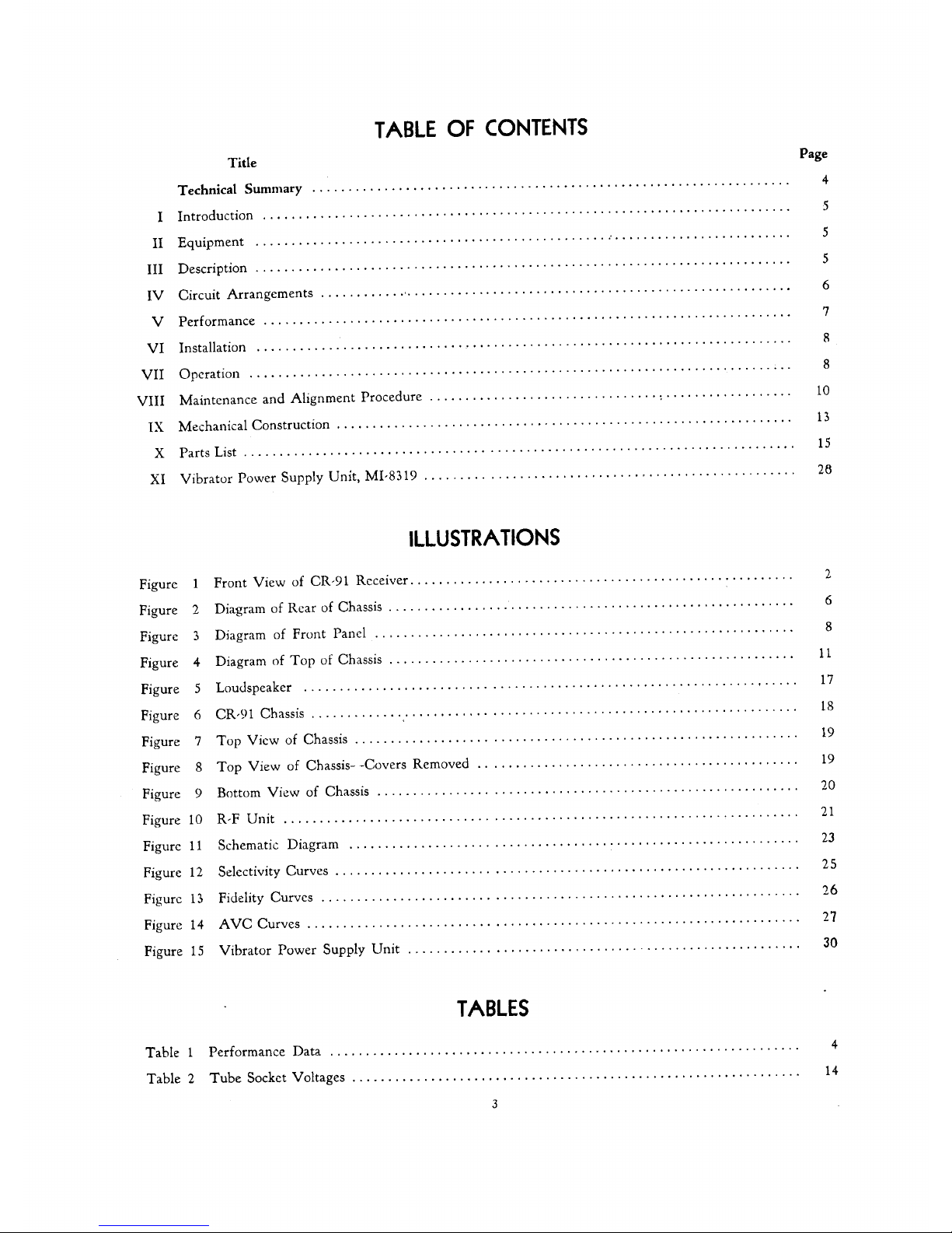
TABLE
I -
PERFORMANCE
DATA
(Appr
oximate
Values--Taken
on
Sample
Recei
ver)
Sens
itivity
Anten
na
Input
in
Ant
enna
Inpu
t in
Band
in Microvolts M ic
rov
olts for :20
DB
Microvolts f
or
20
DB
Image
N
o.
Me:gacycJes
for
0.5 waU
Signal·N oi
r.e
Ratio
Signal· Noire Ratio
Ra
tio
1 .077
.5
1.8
10.0
.1
40
.5
1.
8
10.0
Great
e:r th
an
.190
.5
1.8
10.0
1,000,000
2 .205
.6
1.0
7.0
,375
••
1.
0
8.0
G reater than
.5
00
••
1.5
10.0
1,000,000
3
•
I.
• .5
1.5
11.0 1,000,0
00
3.0
.7 1.3
10.0
4.0
.5
1.3
10.0 25,
000
,
4.5
••
2.0
12.0 500,000
1
1.
0
••
1.5
10.0
9,000
5 12.4 1.0 2.0
n.o 15,000
19.0
.5
2.0
12.0
3,5
00
6
20.0
2.0
2.0
11.0
3,5
00
30.0
1.
0 2.0
13
,0
600
•
.
.
I-F
reje
ctIOn
at
1600
kc IS
800.
000
.
4
.
Page 7
Page 8
Page 9
Page 10
•
VI
INST
ALLA
TION
Power
Supply
. T he
power
supply circuit
is in-
tegral
with
tht
: receiver.
Determine
line voltage
and
fr"yuency
and
check
with
the
rattng
of
the
receiver.
The
po\ver
transforrncr
prilnary
T1lity
he
connected
for
anyone
of five volt;lge
ran
ges by mea
ns
of
Cl
L1.
p
switch.
This
switch is
lo,·
~t e
d
in
the
rear
apron
of
the
r
ecei\'e
r~
and
the
voltage for \vhich it
is
set may he
read
directly
un
the
.switch.
For
Battery
or
other
Supply
Operation -For
con-
nections sec Sl'hc.malic Diagram
figure
11.
It
is
only
neccss,lry to re
move
the
plug
fro
m
th(
~
socket
on
the
rc
;.tr
of
the
n.::
-:.,;'ivcr. ,mu
conne
ct
the batteries
to
the
prop
er
tl~rrninid.
s
as indicilted hy
thl~
schema
tic
dia
~
gr'\n1.
A.
hattcry cahle
terminating
in
an
o::tal
mal
e
pl
ug
IS
Il
ccc5s
ary
for
thi
5
purpose
. A
vlbr;ltu
r
po\v
cr
sup
ply MI-
S:;
I 9
i.
available which will
opera te
the
re
ceiver uircctly from a 6
vD
lt storage
hattery.
For
inforl11,lti
Ol1
011
this
110\v
cr
unit
SI;'~C
Section
XI.
Tubes
Insp
ect the chas.,.;s
before
applying
power
tu
see
that
all
tuhes
arc
firmly seated in
their
respec·
tive sockets.
Antenna
.. The
input
Impedance
at
the
ant
enna
terminals
is desi.gned
to
match a 200
ohm
transml
s"
sion.
line
or a st
raigllt
wire capaLity
t~
:pc
antenna.
For
gl,;~neral
use
it
is
recnmmcnut
:d th
at
a s
traight
\""1[
('
an
tenna
hetween
25 and
50
fec
t long he used
for
hands:'
to
6
inLlu.sive~
an d a
WI
fe
of
200
fCt~
t
or
more
for
hand:; 1 and
2.
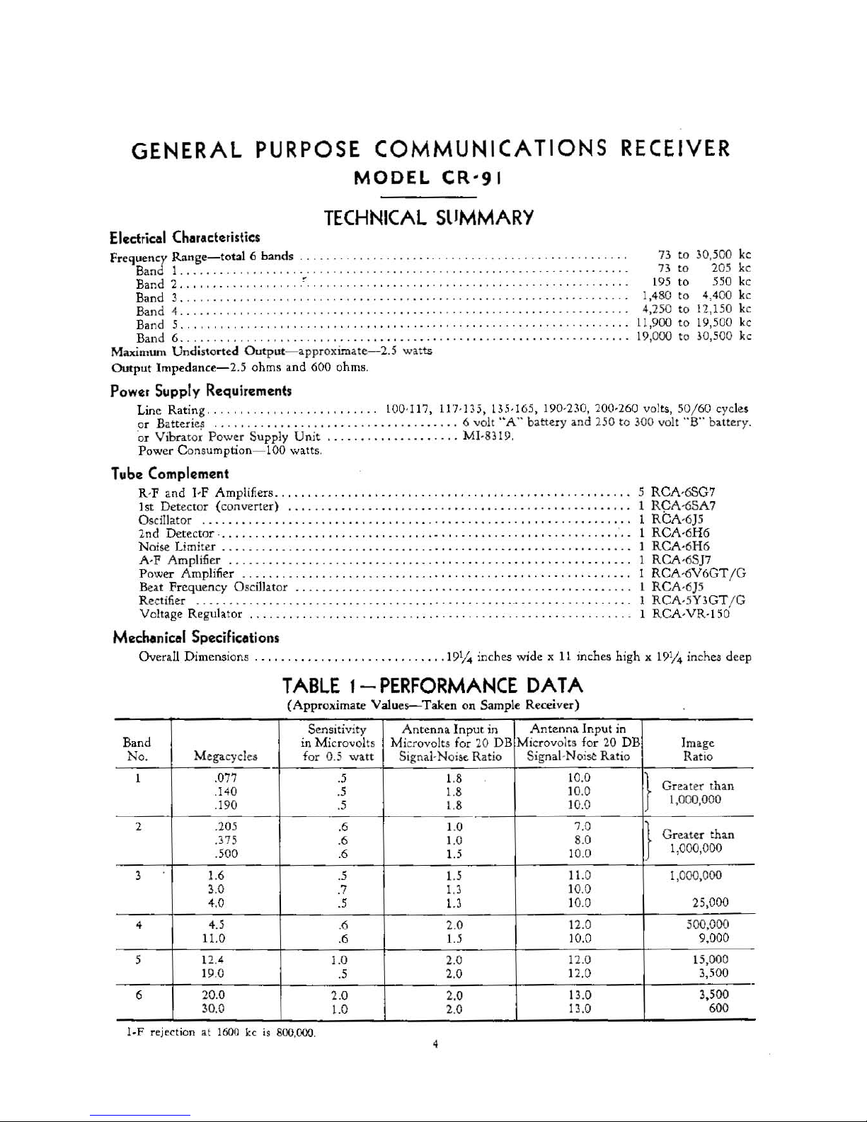
Speaker -Terminal
s for
connection of a loud-
speaker
are
indicated
in
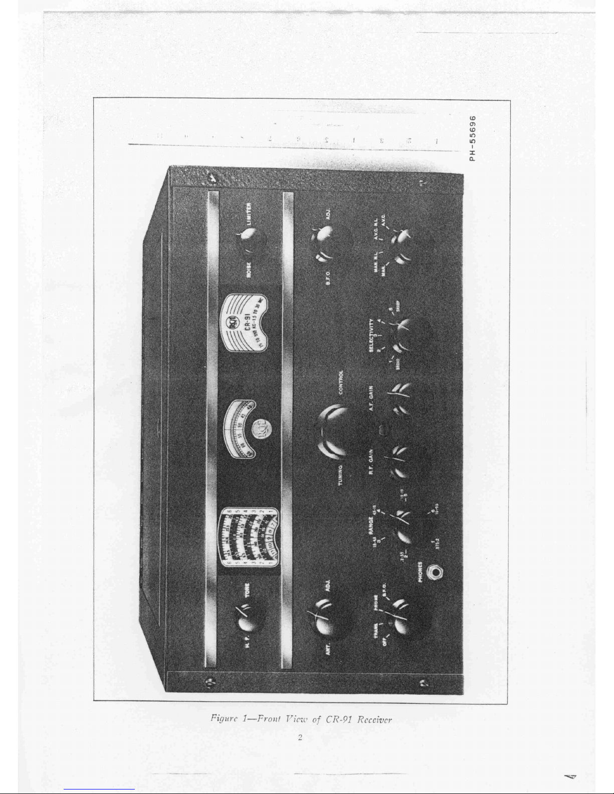
Figur
es
'2
and
6. The output
transformer
is
designed
to
mat
ch a
speaker
having
7.5
ohms
ilnpedanc
e.
Headphone
.,
A jack is
proviueu
on the l
eft
of
the
front
panel for plugging in a pair
of
headphones.
T
here
a re
l\VLl
posit
ions
of
the plug.
1.
Half
way
in
-,--for r c:ct':pt io
ll
on
hnth
speah::r
and
phones. .
2.
F\llIy in
ior
phone
rece
pti
on onl
y.
See
"CIRCUIT
ARRANGEMENT"
"Output
Tub
e. "
MO\lnting _.-
The instrument
may be placeu on a
tahle
or mounted
on
a r
al.".k.
For
rack mouncing loos
en
the
p;tncl
mounting
scr(~\
\'s
anJ remove
the
panel
and
ch
assis cn
mpletc from
the
cabinet. The:
panel
is
cquippe
J.
with
slilll
c.larcl
sl()ts
for
rack
mounting.
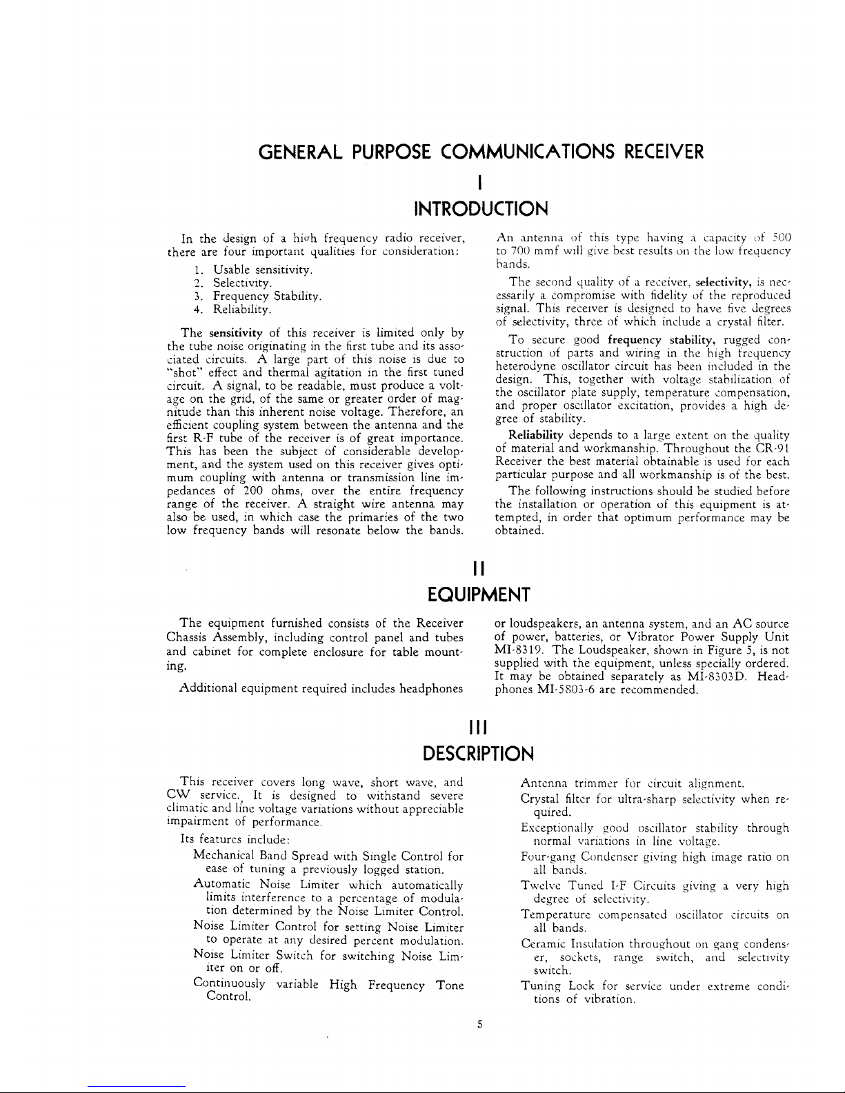
VII
OPERATION
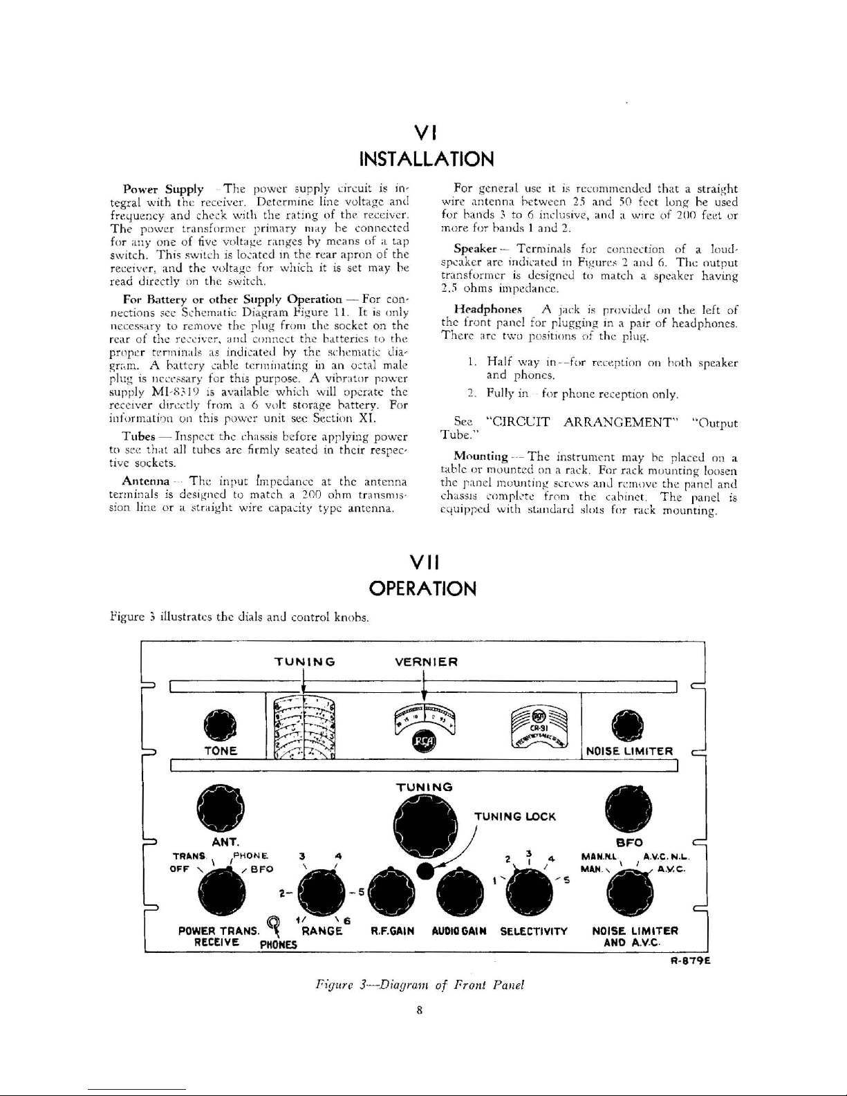
Pigurc 3 illustrates t
he
dials anJ
control knohs.
TUNING
TONE
TRIINS
.
OFF "
ANT.
....
BFO
3
~-'.
(
(
,
,
~~
4
, ,
)
)
-
POWER
TRANS.
~
RANGE
RECEIVE
PHONES
- 5
VERNIER
TUNING
LOCK
4
R.F.GAIN
AoUDIO
GAoIN
SELECTIVITY
Figure 3 Diagram
of
Fron' Pallel
8
NOISE LIMITER
BFO
MAN.N.L.
I
MAN
.,
I
A.V.C. N.L..
A.V.
c.
NOISE LIMITER
AND
AV.C.
R-879E
Page 11

Page 12

Page 13

Page 14

Page 15

Page 16

Page 17

Page 18

Page 19

Page 20

•
525
OUT
TRANSMITTER
RELAY
OIVERSIT'f
~~,
Figure
6-C
R-91
Cl!a
u is
18
I
,
I
,L2
,
L4
ANTENNA
PH-5!5697
Page 21

Page 22

Page 23

Page 24

Page 25

Page 26

•
, KC.)
" "
""
6
"'7
,
....
.
~
'
..
,;ru...
. .
<f~"
..
...
'-
.~H'
'H
__
H'",-' ..
.. ,.D.
,---
·)
T~""''''
,
" .
......
v
.-
--
-
~
__
_ _
OIv
~Il&I"'"
n<
"<fIlMs
'.
2.
__
urtAKAI._~
~OO.f\.
-':
0.
FigllY
(, 11-S
rlulJl
atic Diagra/ll
Page 27

10,000
1,000
....
"
..
z
-
...
..
:r
a:
LOO
o
Z
..
..
:r
-
....
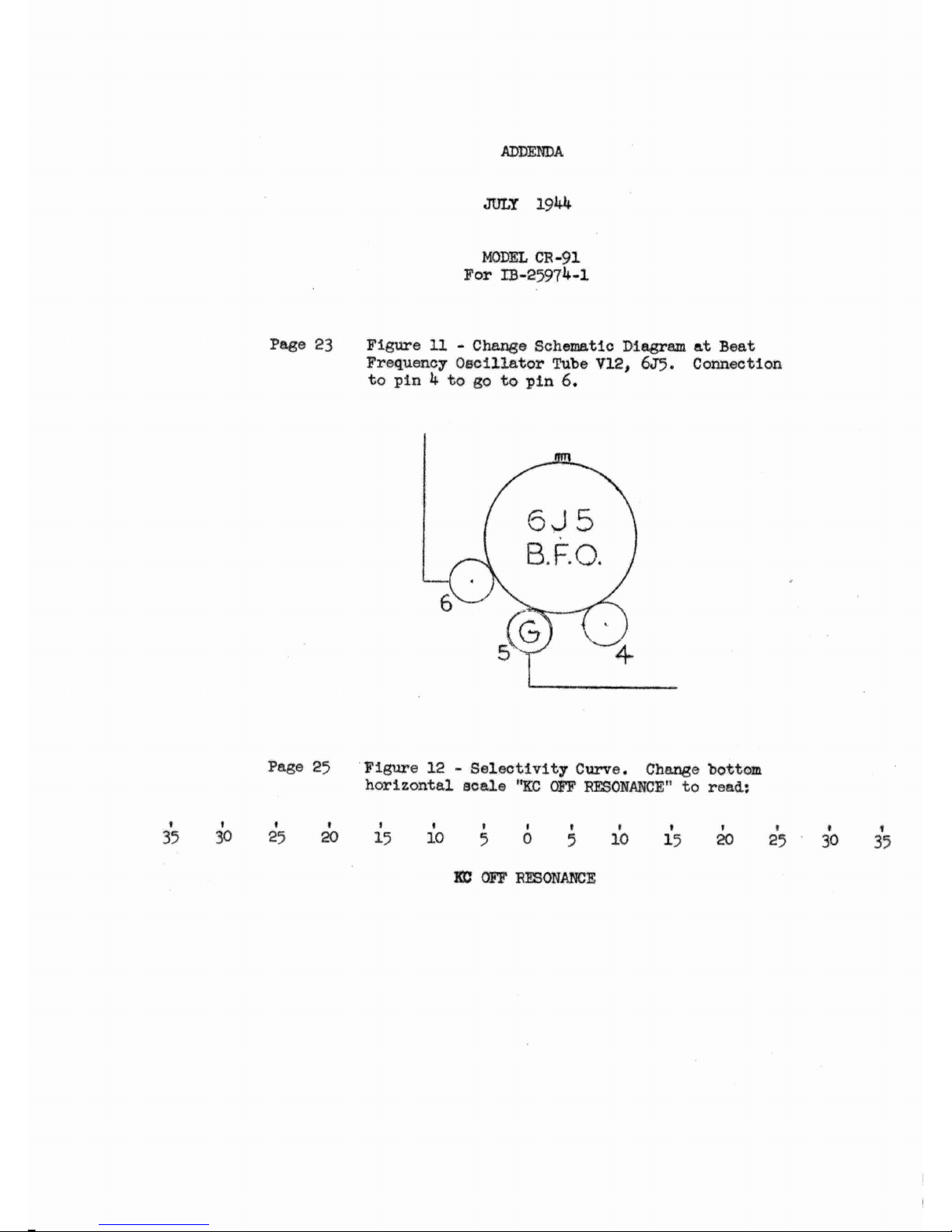
KC
OFF
RESONANCE
12-Se/ectivity
,.
-,
,
•
Page 28

o
11
Cl)
•
-
•
•
•
•
..
....
•
-
C\I
•
-
o
•
-
Figure 13 Fidelity C
llYVC
S
26
ID
o
"
o
,
zz
00
--
1.':+
--
11(1)
00
D.1l
-t\!
0"·
Z
zz
0--
u
..
:IX
Ut
oCJ
Ittt
III
~~
a.
••
• »
~
,..1-
u
--
>-
~~
u
~I-
00
11111/
.J..l
111111
«nil)
I I
~N
1LIU1
»
a:
It
~:::J
ou
•
Page 29

Page 30

XI
VIBRATOR
POWER
SUPPLY
UNIT
MI-8319
(6-VOLT
STORAGE-BATIERY
OPERATION)
TECHNICAL
SUMMARY
Electrical Characteristics-
Output
....
, . . . .
.. , ...
.... , .......
..... , ....
.. .. ..
......
......
...............
.
..
~OO
volt
s,
90
rna,
B;lttcry
\
lollil~e
..........
,
...................
. .
....
......... ...... ...... .
....
........
6 to 8
vo
lts
Tot
al current
dra
in
(opera
ting
l\R·8S
rc~ci\.'cr)
....
......... .
...
...
....
............
.
.......
12
ampc.rc5
Fuse
Rati
ng
_, ...
. .
.............
.
.................
..........
.........•.... , ..
. , . . . . . . . . 15
amperes
Tube Complement. . . . . . . . . . . . . . . . . . . . . . . . . . . . . . . . . . . . . . . . . . . . . . . . . . . . . . . . . . . . . . . .
..
1
RCA-OZ
4
Mechanical Specifications,-
Dim
ens
lons···--
H eig
ht
Witlth
. . . . . . . . . . . . . . . . . , . . . . . . . . . . . . . . . . . . . . . . . . . . . . . . . . . . . . . . . . . . . . . . . . . . , . . . . . . inc
hes
inc
hes
. . . . . . . , . . . . . . . . . . . . . . . . . . . . . . . . . . . . . . . . . . . . . . . . . . . . . . . . . . . . . . . . . . . . . . . . . . .
..
5
De
ptll ..
....
.......
...
........
.. ..
..........
.
......
..
. ...• .....
........
...........
5
1
/;
i
nches
--
Weight
(net) ....
........
.......... .
...
..............................
...
...............
7 po
unds
EQUIPMENT
Th
e MI,831 9 identifie, t
he
equipment
furnished
with
the
power
suppl
y Ullit
and cons
ist
s o f
the
fo11
o\'l.'
"
ing
items:
I--Vihrator Pow
er
Supply
un
it,
complete
wIth
vi-
br
ator
and RC.A·OZ4
re ctifier t
ube
.
I-Power
Cable. approximately 8 f
ect
long, e
quipped
\vith
pOV"tc
-r
EWltch,
fuse hol
der
and
fuse, t e
rmi
naLs for
co
nnecting
to the vibra
tor
power
supply unlt.
and
l
erminat
in~
to
a plug f
or conncctmg
to lhe.
a sso
~iatt::d
•
receI
ver.
DESCRIPTION
Th
e
MI,g
319 vi
brator
power
supply
unit
is pri·
marily designed inr
the
purp
ose a
t"
adapt
ing
the
Gen
-
er
al
Purpose
CommU
IlI
catlOn
Re
cei
ver
(Model
AR
-gS )
to
6-vo lt ha
tte
r), ope
rat
ion F
our
rubhef
feet
"rc
rrov
,oetl for rest ing
the
uni t on a
tah
le or shel
f.
If
preferr
ed,
the
se feet may be
removed
to
expo
se
thr
eaded
stud
s b),
which the Untt may he bolted
pef
'
manentl
y
ill
posItion.
NOTE-The
power
supply
unit
must
he mounted
with
th~
vibrator
in
an
appr(lximately
vertical posi-
•
tlOn.
Dir
e" ,
'ur
rcnt at high pot cnti;d is
obta
inetl by
means. o f
,!
n
0l1~sync
hr0T1{)lb
vibr
ato
r used in
;,:onj
u n
c~
tion
\\11th ,":
ste p -up transt':"l
rm
e:-.
Rectification
i
~
ob-
talOed hv
th
e use
of
an
RC.A-OZ4 rC'c
tificr tub
e,
This
-
power
U:11l
has
bee.n desHmfJ
anu
testeD to
ope
rate
und
er
a v .
.!1
dl'
\"
'l.rielY
01 chma
ti.;:
con
ditions
.
INST
ALLA
nON
Connecting
the
Power
Cable to
the
Vibrator
Power
Supply Unit
-: ·1:1 ord
er
to co nnect
the
nnwe r cable to
th
~
vibrator p
ower supply
unIt, first
r
~movc
th
e: tcr
-
minal boanJ
cover
from
the
powe
r
Uni
t hy re
movin
g
the t
wo sclf-tapPlng
s..::
rc ws in the ('()vcr.
/\h
llut
fo
ur
f':'2t i
rom thl.:
enJ
()f
lh
e La
hk
tu which
the
( W ( I
la
rge
•
ha.tter~'
('l
q:'!.s
~r('
iltta..:hcd.
it
~rou
r
of
fou
r
\l,,' in~:;.
e
ach
aODul
{()
llr
lll(:hc~
l
ong and
eqUIpped
wlth
~~
spaJ:::
Page 31

terminal,
extends
from
the
cable.
These
leads
should
be
connected
to
the
power
unit
terminal
board-the
brown
lead
to
the
termlnal
marked
"A-HOT,"
the
yellow
lead
to
"B-"
and
the
red
lead to
"B+."
Re·
place
the
terminal
board
cover
with
the
three
leads
extending
from
the
open
end
of
the
cover,
connecting
the
black
lead
under
one
of
the
screws
which
hold
the
cover.
Mounting
the
Switch-Fasten
the
switch
to
the
bracket
on
the
top
of
the
transformer
can.
Connecting
the
Power
Cable
to
the
Receiver-Re-
move
the
plug
from
the
socket
on
the
rear
apron
of
the
receiver.
Insert
the
plug,
on
the
end
of
the
vi-
brator
power
supply
cable,
into
this
socket.
Adjustments-A
four-position
rotary
sWitch
on
the
rear
of
the
chassis
is
used
to
adjust
the
vibrator
out-
put
voltage
to
compensate
for
variations
in
the
bat-
tery
voltage.
The
positions
on
this
switch
are
num-
bered
from
"1"
to
"4"
lnc1usive.
The
position
in
which
the
sWitch
rotor
is
placed
is
indicated
by
the
direction
in
which
the
screwdriver
slot
in
the
rotor
shaft
is pOlOtlng.
For
proper
selection
of
the
switch
positlOn,
consult
the
following table:
Switch
Position
Battery
Voltage
4 6.0 to 6.5
volts
3
6.5
to
7.0
volts
2 7.0
to
-"
1.
)
volts
I
-.
, . J
to
8.5
volts
Connecting
the
Power
Cable
to
the
Storage
Bat·
tery-
Turn
the
power switch in
:he
power
cable tu
the
"OFF"
position.
There
are
two
hattery
clips coO'
nected
to
one
end
of
the
power
cable. each
dip
serv-
ing
to
terminate a pair
of
wires.
On
one
dip,
both
wires
are
black while
on
the
other
dip
one wire. IS
green
and
the
second
IS
brown.
Connect
the
dip
with
the
two
black wires securely to
the
negative
(-)
ter'
mmal
of
the
storage
battery.
Be sure
to
make good
contact
at
this
point.
Connect
the
cbp
with
the
green
and
brown
wires securely to
the
positive
(+)
ter-
minal
of
the
battery.
The
receiver
is
now
ready
for
operation
from
the
power
supply
unit.
NOTE-Since
the
power
line
cord
supplied
with
the
receiver
is
completely
out
of
the
circuit
when
the
vibrator
power
supply
is
used, this
cord
should
be
wound
up
and
placed inside
of
the
receiver case
in
the
space
between
the
chassis
and
the
case wall.
OPERATION
The
switch
on
the
power
cable
must
be
used
for
turnlng
the
receiver
on
and
off,
the
power
switch
on
the
receiver
being
automatically
cut
out
of
the
circUlt
when
the
vibrator
power
supply
unit
is
used.
To
pre-
vent
impairment
of
normal
operation,
the
following
precautionary
measures
should
be
observed:
l.
Never
remove
the
rectifier
tube
while
the
power
supply
unit
is in
operation.
Serious
damage
to
cir'
cuit
elements,
or
even
to
the
vibrator
itself,
may
re'
suit
under
these
conditions.
2.
Never
disconnect
any
leads
on
the
power
cable
unless
the
power
switch
is
turned
off.
Never
llghten
any
t(rmmal
screws
unless
tbe
power
is
definitely off.
Should
it
become
necessary
to
tighten
any
or
all
of
thc
screws
on
the
vibrator
power
unit
terminal
board,
always
first
remove
the
battery
clips
from
the
battery.
TIns
IS
EXTREMEL Y IMPORTANT,
SINCE
FAILURE
TO
FOLLOW
THIS
RULE
WILL
IN·
VARIABLY
RESULT
IN
SERIOUS
DAMAGE
TO
THE
VIBRATOR
POWER
UNIT
ITSELF.
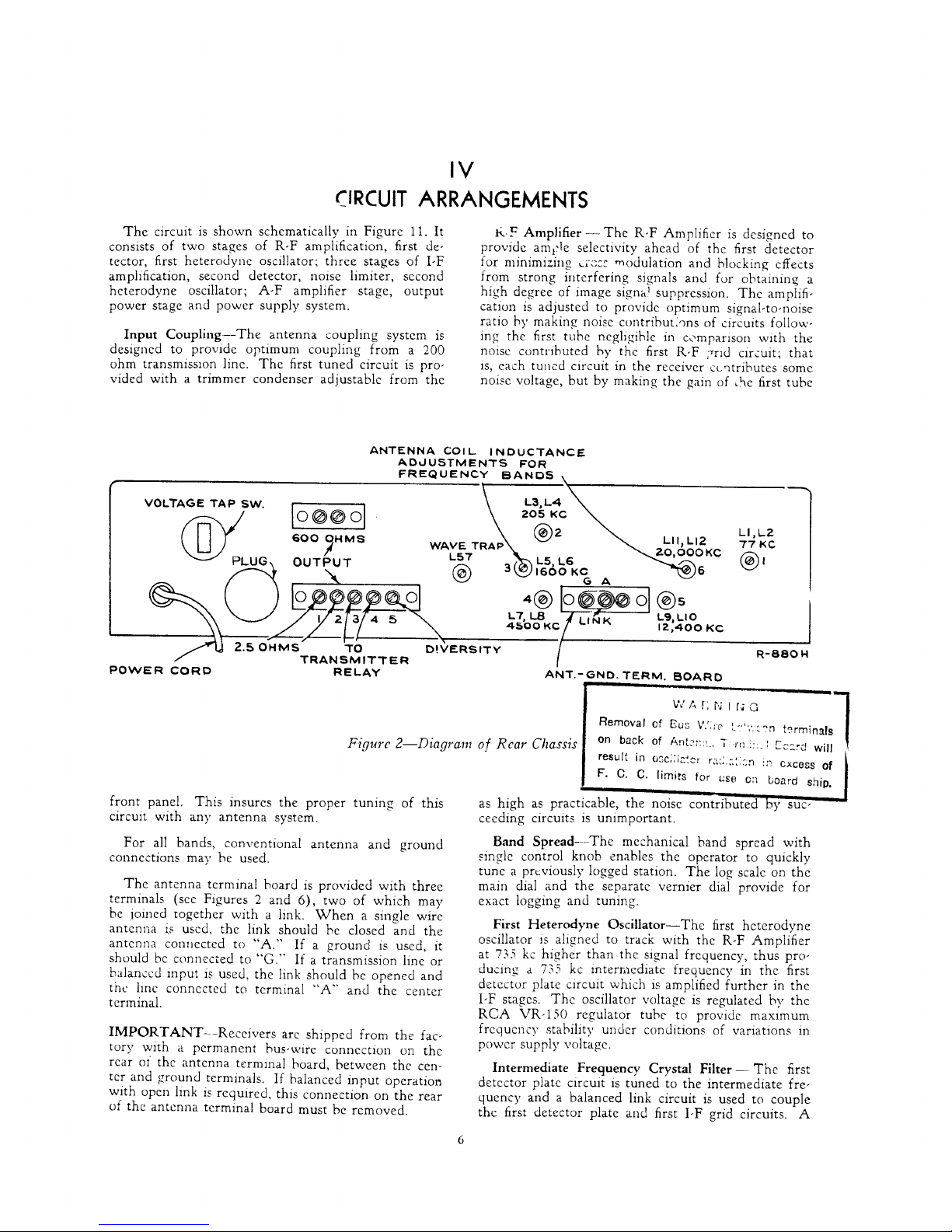
MAINTENANCE
A
schematic
diagram
of
the
vibrator
power
supply
unit
is
shown
in
Figure
1
s.
The
diagram
symbol
of
each
part
is
repeated
in
the
parts
list to facilitate iden-
tification by
means
of
cross
reference.
Service
generally
consists
of
replacing
the
vibrator
which
may
have
deteriorated
through
prolonged
usage.
If
excessive
output
hum
should
occur
dunng
operatlOn,
the
cause
may
be
a filter-circuit
breakdown,
such
as
leaky
or
short·circUlted filter capacitors.
29
When
servicing
the
power
supply
unit,
disconnect
it from its
source
of
voltage
supply
and,
using an
ohm~
mt~ter)
check
through
for
cuntinuity.
Capacitors
should
be
tested
by
first
removing
one
Side
from
the
adpcent
connectlO05 so
that
the
ca-
paCItor
under
test
is
not
connected
in
the
Clrcult.
The
power
supply
unit
IS
protected
by
a
l.i-ampere
fuse
which
in the
event
of
failure ,;hould be replaced
by
one
of
identical rating.
Page 32

Symbol
Designation
Cl
C2
C3
C4
CS, C8
C6
C1
El
LI
L2
•
-
~
•
~
"
~
>
c
•
•
+
PARTS
LIST
Sto
ck
Symbol
Description
No.
Designation
Description
Capacitor, 0.5
mf<L,
SO
v.
. . - . . . 18080
PI
Plug,
8-prong,
power
cable
• • • • •
Capacitor,
0.005 mid" 1,600 v.
. . . 63813
RI
Resistor,
5,000
ohms
. . . ,
. . .
. .
Capacitor
, 0.05 mId., 600 v ..
...
. .
63814
SI
Included • Cable
Wl
In
.
- - . . . . . .
Capacitor,
0.1
mfd.,
600
'17
. . . . . 63815 52
Switch-voltage
tap
. .
· . .
. . , .
. .
Capacitor
, 0.0005
mid.,
•
63816
Tl
Transformer,
power
mJca ...
. . .
· .
- . . . . . . .
Capacitor,
10
mid.,
450 v .
....
. . . 63817
TBI
Terminal Strip,
external . . . , .
. .
Capacitor, 2S
mfd.,
40
v .... .
....
.
63818
Wl
Cable, power
. . . . -
. .
·
- . . . . . . . .
Vibrator . . . . . . . - - . . . . . . . . . . . .
63821
TSl
So
cket tube, octal . . . . . . - . . . .
Choke,
HA"
line
-. -."""
- . . , .
63820
VSl
Socket,
vibrator, 4-pin
Choke,
HB'to
line
. . . . . . . . . . . . . . 63811
--
---
---
- _
.......
- -
----
- -
-----
----------,
I VIBAATOA TAAHS. 1
1 RED
SWITCH
1
1
BLAC~
72
I
I1
N RECTiFIER
11
ACA-OZ4
I
I
I
I
1
1
1
I
I
I
1
I
I
I
I
Ll
I ce
,
SlOWII'.
11
CON.leT
u"DEIII
TUMINAL
CO'IU
I
le"fW
I
I
I
.- YEL .
O-~-
BLK
.- YEL .
..:C=--
____
_
-!--RED-YEL.
L2
ST1tt.
C5
500'''''
,
C6
10""D
4$OV
.
I
1
1
I
I
1
1
I
1
I
I
I
1
I
I
I
1
I
I
1
1
I
1
· . . . . . . . , .
Stock
No.
35383
37122
37119
63810
63819
63822
31251
31769
....
-
-------
- - - -
-----------
_J
WI
&CA8LE
--
--
,
B
,
•
--
--
--
--
--
--
--
YEL
RED
GRN.
BRN
--
--
--
--
--
--
Fi
gure 15-Vibrator Power
SuNly
Ullil
(Sc
helllatic Diagralll
],
1-253
452)
.1
0
--
--
-'-
 Loading...