

Page 1
Copyright © 2015 RCA Communications Systems
1BRM300DTM Professional Digital Two-Way Mobile Radio Instruction Manual
Congratulations on selecting the BRM300DTM from
RCA Communications Systems - The most trusted name in radios!
The BRM300D digital professional communications products are based on DMR technology and
establish a benchmark in premium digital two-way radio equipment. These radios are made to
perform awlessly under the most demanding commercial conditions and feature cutting edge
design, high-end professional grade materials and components, simple operation and superior
assembly quality. BRM300D mobiles and base stations are covered by a three-year “Warranty
Protection Program,” one of the most comprehensive warranties in the communications industry.
To ensure you achieve maximum performance from your BRM300D radio, please be sure to carefully
read this manual.
MODELS COVERED IN THIS MANUAL:
• BRM300DV - VHF Two-Way Radio
• BRM300DU - UHF Two-Way Radio
Page 2

Copyright © 2015 RCA Communications Systems
BRM300DTM Professional Digital Two-Way Mobile Radio Instruction Manual
2
Technical Specications...................................4-5
Safety and General Information.......................6
Product Inspection..............................................7
Transceiver Preparation ...............................8 - 13
Installation/Tools Needed....................................8
DC Power Cable Connection ......................9 - 10
Mobile Installation ..........................................10
Fixed Station Installation .................................10
Replacing Fuses ..............................................11
Antenna Connection ......................................12
External Speaker ............................................12
Microphone Jack ............................................12
Microphone Hanger .......................................12
Transceiver Features ...................................13 - 14
Operational Status Indicators ....................15 - 17
Making/Receiving Calls .............................17 - 18
Select A Channel ...........................................18
Setting Squelch Level ...............................18 - 19
Switching Between Analog/Digital Mode .........19
Programmable Buttons ..............................19 - 20
Accessing Programmed Function/Menu ...........21
Keypad Mic (Optional)* ...................................21
Using Menu/Programmed Functions ........22 - 27
Selecting a Zone ..............................................22
Selecting Radio Channel/Subscriber/Group ID ...22
Receiving/Responding to a Radio Call ...............22
Receiving/Responding to a Group Call ............22
Receiving/Responding to a Private Call ............23
Receiving an All Call .......................................23
Monitoring a Channel (Analog) ........................23
Making a Radio Call .......................................24
Making a Call With Channel Selector Buttons ..24
Making a Private Call .....................................25
Making a All Call ............................................25
Making Group/Private Call W/1 Touch Button ...25
Emergency Operation .....................................26
Initiating/Responding to Emergency Alarm ......27
Exiting Emergency Mode ...............................27
Advanced Features .......................................27-51
Public Address ................................................27
Radio Check ..................................................27
Sending a Radio Check ...................................27
Remote Monitor ..............................................28
CONTENTS:
Page 3

Copyright © 2015 RCA Communications Systems
3BRM300DTM Professional Digital Two-Way Mobile Radio Instruction Manual
Initiating Remote Monitor ..............................28
Contacts Settings ...........................................29
Group Call from Contacts ..............................30
Private Call from Contacts ..............................30
Call Indicator Settings/Call Tones .....................30
Call Tones for Text Messages ...........................31
Assigning Tone Alerts ......................................32
Accessing the Call Log....................................33
Storing Alias or ID from Missed Call List..........33
Deleting a Call from the Call List........................33
Receiving & Responding to Call Alert..............34
Making Call Alert from Contact List................34
Text Message Features ....................................34
Navigate to Message.......................................35
Receiving/Reading a Text Message ..................35
Managing Received Text Messages ..................35
Viewing Inbox Text Messages .........................35
Writing/Sending Text Message ........................36
Sending a Quick Text Message........................36
Managing Fail-to-Send Text Messages.............37
Resend a Text Message...................................37
CONTENTS continued
Forwarding a Text Message.............................38
Managing Sent Text Message ............................38
Viewing Sent Text Messages............................38
Deleting All Sent Messages from Sent Items .....39
Replying to an Inbox Text Message...................39
Deleting a Text Message from Inbox ................40
Privacy ..............................................................41-42
Dual Tone Multi Frequency (DTMF)................42
Security ............................................................42-43
Radio Disable .................................................42
Radio Enable ..................................................43
Scan Lists ..............................................................44
Viewing an Entry in the Scan List .....................44
Scan Instructions and Methods........................44
Starting and Stopping Scan ..............................45
Responding to a Scan........................................45
Deleting/Restoring A Nuisance Channel.....45-46
* = MM300DK Only
Page 4
Copyright © 2015 RCA Communications Systems
BRM300DTM Professional Digital Two-Way Mobile Radio Instruction Manual
4
Utilities .................................................................46
Keypad Locked/Unlocked* ..............................46
Keypad Tones* ..............................................46
Setting the Power Level...................................47
Voice Operating Transmission (VOX) On/Off .....47
Controlling the Display Backlight ....................48
Talkaround........................................................48
Turning Radio Tones/Alerts On or Off ............49
Turning the LED Indicator On or Off ..............50
Turning the Introduction Screen On or Off .....50
Accessing General Radio Information/Checking
Radio ID ............................................................51
Care and Cleaning ...........................................51
Troubleshooting ........................................52 - 53
Optional Accessories .................................54 - 55
FCC Caution ......................................................56
RF Exposure Compliance/Control Guidelines ......56
Warranty Statement ........................................ 57
Contact Information ........................................60
CONTENTS continued
GENERAL
Model BRM300D
TM
Frequency
VHF: 136-174MHz
UHF: 400-470MHz;
UHF: 450-520MHZ
Number of Channels 1,000
Max number of zones 250
Channels per zone 16
Channel Spacing
Digital:12.5KHz
Analog:12.5KHz/25KHz
Power Supply 13.6V DC +/-20%
Operating Temperature
-22°F ~ 140°F
(-30°C ~ 60°C)
Weight 2.9 lbs / 1,315 g
Size:HxWxD
1.8” X 6.3” X 6.9”
46 x 160 x 175mm
IP Standards IP56
Digital Protocol ETSI TS 102 361-1,-2,-3
Vocoder AMBE+2
TM
Audio Distortion <3%
TECHNICAL SPECIFICATIONS:
* = MM300DK Only
Page 5
Copyright © 2015 RCA Communications Systems
5BRM300DTM Professional Digital Two-Way Mobile Radio Instruction Manual
Technical Specications continued:
RECEIVER
Analog Sensitivity
0.35μV/-116dBm (20 dB SINAD)
0.22μV/-120dBm (12 dB SINAD)
Digital sensitivity
0.3μV/-11.4dBm (BER 5%)
0.7μV/-110dBm (BER 1%)
Intermodulation TIA603C: 70 dB, ETSI: 65dB
Adjacent Channel
Selectivity
TIA603C: 65dB
ETSI: 60dB
Spurious Rejection TIA603C: 75dB; ETSI: 70dB
Co-channel rejection -8dB@12.5KHz
Blocking 84dB
Audio Distortion @
Rated Audio
5%
Audio Response +1~-3dB (300-3,000Hz)
Conducted Spurious
Emission
-57 dBm <1GHz, -47 dBm>1GHz
ETS300 086
TRANSMITTER
Frequency Stability +/- 1.0 ppm
Transmit power -
L, M, H
5W, 25W,
45W(UHF)/50W(VHF)
Modulation Limiting +/-2.5KHz@12.5KHz
FM noise/hum -40dB (12.5KHz)
Conducted/Radiated
Emission
-36dBm@<1GHz,
-30dBm@>1GHz
Adjacent Channel
Power
-60dB
Adjacent Transient
Channel Power
-50dB
FM Modulation Mode
12.5KHz: 11K0F3E
25KHz: 16K0F3E
Nonactive slot power -57dBm
4FSK Digital Mode
12.5KHz Data: 7K60FXD
12.5KHz Data/Voice: 7K60FXE
4FSK Modulation
Accuracy
5%@77°F,
10% @ extreme temperature
Audio Response +1~-3dB (300-3,000Hz)
Page 6

Copyright © 2015 RCA Communications Systems
BRM300DTM Professional Digital Two-Way Mobile Radio Instruction Manual
6
SAFETY AND GENERAL INFORMATION
This radio is restricted to occupational use only
to satisfy FCC RF energy exposure requirements.
Before using this product, read the operating
instructions.
• Do not transmit using high output power
for extended periods as the transceiver may
overheat.
• Turn radio off prior to entering any area with a
potentially explosive atmosphere, such as gas,
petroleum, chemicals, blasting caps, etc.
• Do not attempt to congure your transceiver
while driving. Be aware of local laws regarding
the use of headsets while driving.
• This equipment is to be serviced only by
authorized RCA Communications Systems
technicians. Any service performed by
unauthorized technicians will void the warranty.
• Turn radio off when near electrical blasting
caps to avoid possible interference with blasting
operations. Obey posted signs such as those in
hospitals or blasting areas advising people to
turn off all two-way radios.
• Do not place radio equipment over an air bag or
in an air bag’s deployment area, as an inated
air bag could propel the equipment and cause
serious injury.
• Do not place the radio close to a heat source
or expose the radio to direct sunlight for a
prolonged time.
• Do not place the transceiver in an excessively
dusty, humid or wet area, or on an unstable
surface.
• If smoke or an abnormal odor is detected
coming from the transceiver, turn OFF the
transceiver immediately and contact your RCA
dealer.
For a complete list of RCA approved antennas and
audio accessories, visit:
www.RCACommunicationsSystems.com
Page 7
Copyright © 2015 RCA Communications Systems
7BRM300DTM Professional Digital Two-Way Mobile Radio Instruction Manual
MM300D
Palm Microphone
Mounting Bracket
with screws
Microphone Hanger
with screws
DC Power Cord
BRM300D
TM
Mobile Radio
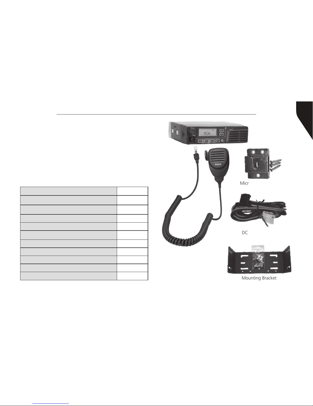
PRODUCT INSPECTION
Prior to unpacking your BRM300D radio, please
inspect the packaging for signs of damage and
report any damage or missing components
immediately to your RCA Communications
Systems Sales and Service Center. Every BRM300D
mobile radio comes with the following items:
Item PCS
Radio Unit (BRM300D) 1
Palm Microphone (MM300D) 1
Microphone Hanger/Screws (3) 1
Radio Mounting Bracket 1
Self-Tapping Screws 4
SEMS Screws (screw/washer) 4
Spring Washers / Flat Washers 4 / 4
Fuse 1
DC Power Cord (w/2 fuses) 1
User Manual 1
Page 8
Copyright © 2015 RCA Communications Systems
BRM300DTM Professional Digital Two-Way Mobile Radio Instruction Manual
8
that knees or legs will not strike the unit during
vehicle operation. Try to pick a well ventilated
location that is shielded from direct sunlight for
your installation location.
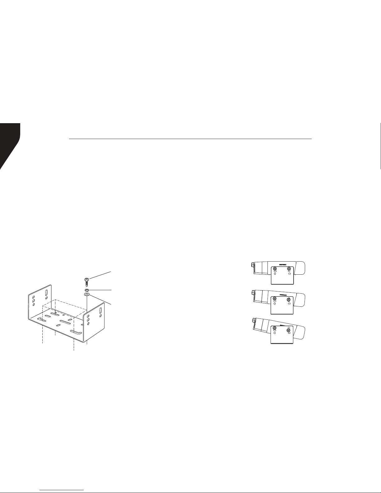
Install the mounting bracket in the vehicle using
the supplied self-tapping screws (4), at washers
(4), and spring washers (4). Position the bracket so
that the 3 long screw hole positions on the side of
the mounting bracket are towards the rear of the
bracket. (Figure 1)
Use the 3 screw positions on the side of the
TRANSCEIVER PREPARATION
Installation/Tools Needed
• Electric drill with 6mm bit or above
• Cross head screwdriver
• Hex socket sleeve (used for mounting 5mm ×
16mm self-tapping screw)
When installing your transceiver, be sure to select a
safe, convenient location. If you’re installing inside
your vehicle, choose a location that minimizes
danger to your passengers and yourself while the
vehicle is in motion. Consider installing the unit so
Self-tapping screw
(5mm x 16mm)
Spring washer
Flat washer
Figure 1
Figure 2
Mounting Bracket
Page 9
Copyright © 2015 RCA Communications Systems
9BRM300DTM Professional Digital Two-Way Mobile Radio Instruction Manual
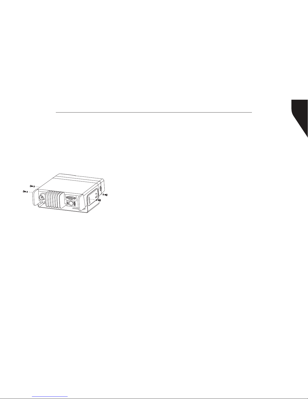
SEMS Screws
Figure 3
(Radio back)
mounting bracket to determine the appropriate
angle of the transceiver. (Figure 2) Position the
transceiver, then insert and tighten the supplied
hexagon SEMS screws (4) and at washers (4).
(Figure 3) Double check that all hardware is
securely fastened to ensure that vehicle vibration
will not loosen the bracket or transceiver.
DC Power Cable Connection
Mobile Operation
Your vehicle battery must have a nominal rating
of 12V. Never connect the transceiver to a 24V
battery. Be sure to use a 12V vehicle battery that
has sufcient current capacity. If the current to the
transceiver Is insufcient, the display may darken
during transmission, or transmit output power
may drop excessively.
1. Route the DC power cable supplied with the
transceiver directly to the vehicle’s battery
terminals using the shortest path from the
transceiver. If using a noise lter, it should be
installed with an insulator to prevent it from
touching metal on the vehicle. We recommend
you do not use the power outlet/cigarette
lighter socket as some power outlets have an
unacceptable voltage drop. The entire length of
the cable must be dressed so it is isolated from
heat, moisture and the engine secondary (high
voltage) ignition system/cables.
2. After the cable Is In place, wrap heat-resistant
tape around all fuse holders to protect it from
moisture and tie down the full run of cable.
3. To prevent the risk of short circuiting, disconnect
other wiring from the negative (-) battery
terminal before connecting the transceiver.
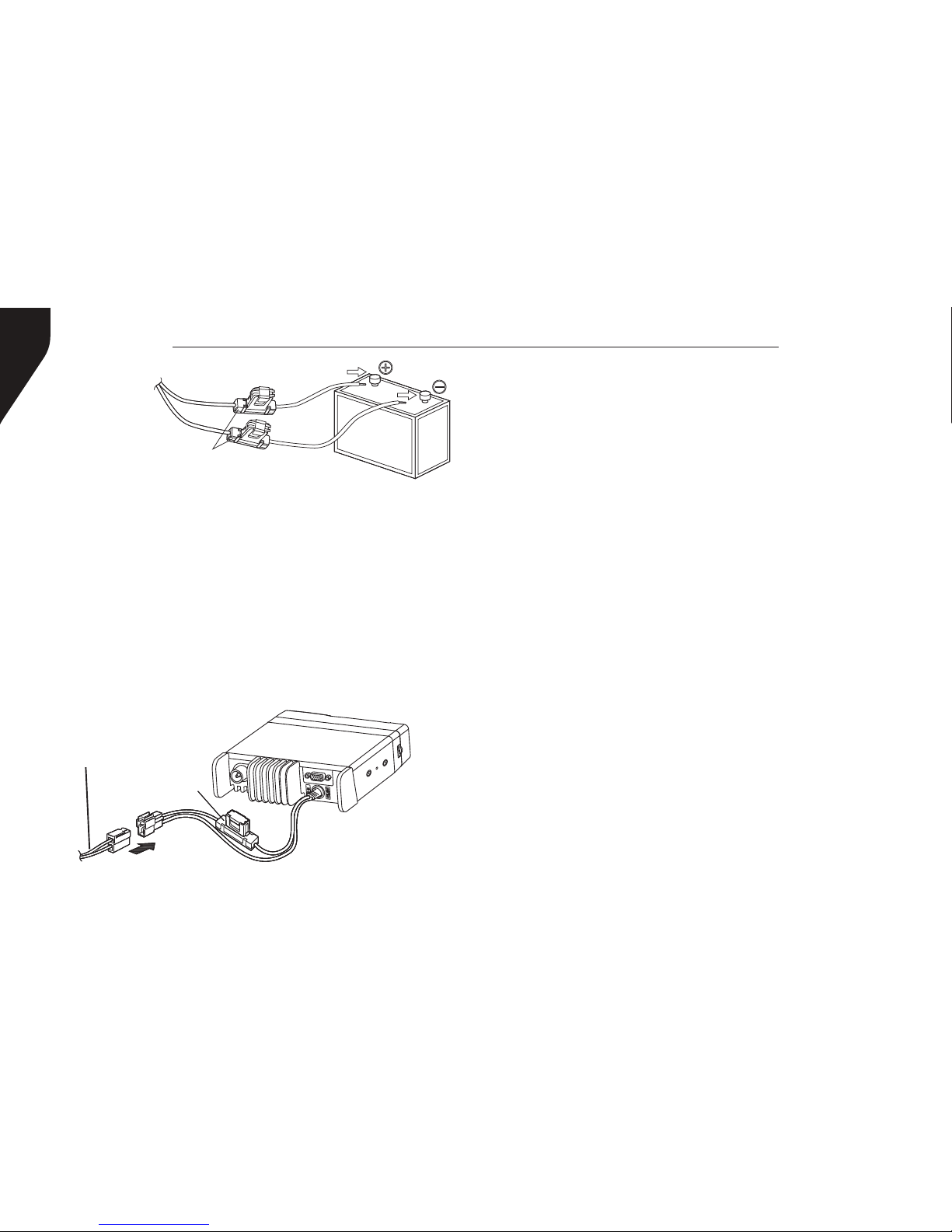
4. Conrm the correct polarity of the connections,
Page 10
Copyright © 2015 RCA Communications Systems
BRM300DTM Professional Digital Two-Way Mobile Radio Instruction Manual
10
Figure 5
Figure 4
Supplied
cable
Fuse holders
Fuse
holder
then attach the power cable to the battery
terminals; red connects to the positive (+)
terminal and black connects to the negative
(-) terminal. Use the full length of the supplied
cable without cutting off excess even If the
cable is longer than required. In particular,
never remove the fuse holders from the cable.
(Figure 4)
5. Reconnect any wiring removed from the
negative terminal.
6. Connect the DC power cable to the transceiver’s
power supply connector. Press the connectors
rmly together until the locking tab connectors
rmly together until the locking tab clicks.
(Figure 5)
Fixed Station Operation
In order to use this transceiver in a xed station
operation, you will need a separate 13.8V DC
power supply (not included). The recommended
current capacity of your power supply is 14A or
more.
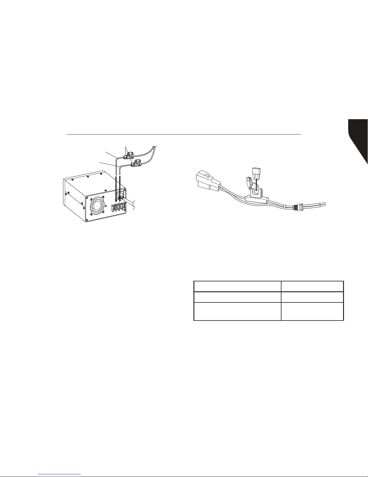
1. Connect the DC power cable to the regulated
DC power supply and ensure that the polarities
are correct (Red: positive, Black: negative).
• Do not directly connect the transceiver to
an AC outlet.
• Use the supplied DC power cable to
connect the transceiver to a regulated
power supply. Do not substitute a cable
with smaller gauge wires. (Figure 6)
Page 11
Copyright © 2015 RCA Communications Systems
11BRM300DTM Professional Digital Two-Way Mobile Radio Instruction Manual
• Do not plug the DC power supply into an AC
outlet until you make all connections.
Replacing Fuses
If a fuse blows, most times it indicates a problem.
Check the power source and the power cables
to determine the cause and then correct the
problem. Once the problem is resolved, replace
the fuse. (See Figure 7.) If newly installed fuses
continue to blow, disconnect the power cable and
contact your authorized RCA Dealer for assistance.
Fuse Location Fuse Current Rating
Transceiver 15A
Supplied Accessory
DC Power Cable
20A
2. Connect the transceiver’s DC power connector
to the connector on the DC power cable. Press
the connectors rmly together until the locking
tab clicks. (See Figure 5)
NOTE:
• For your transceiver to perform properly, we
recommend using a power supply with an
output of more than 23A/25% duty cycle.
• Before connecting the DC power supply to the
transceiver. be sure to switch the transceiver
and the DC power supply OFF.
Black (-)
Figure 6
Regulated
DC Power
Supply
To AC
Outlet
Red (+)
Fuse holders
Figure 7
Page 12
Copyright © 2015 RCA Communications Systems
BRM300DTM Professional Digital Two-Way Mobile Radio Instruction Manual
12
CAUTION
Only use fuses of the specied type and
rating; otherwise the transceiver can be
damaged.
Note:
If you use the transceiver for a long period when
the vehicle battery is not fully charged or when the
engine is OFF, the battery may become discharged
and may not have sufcient reserves to start the
vehicle. Avoid using the transceiver under these
conditions.
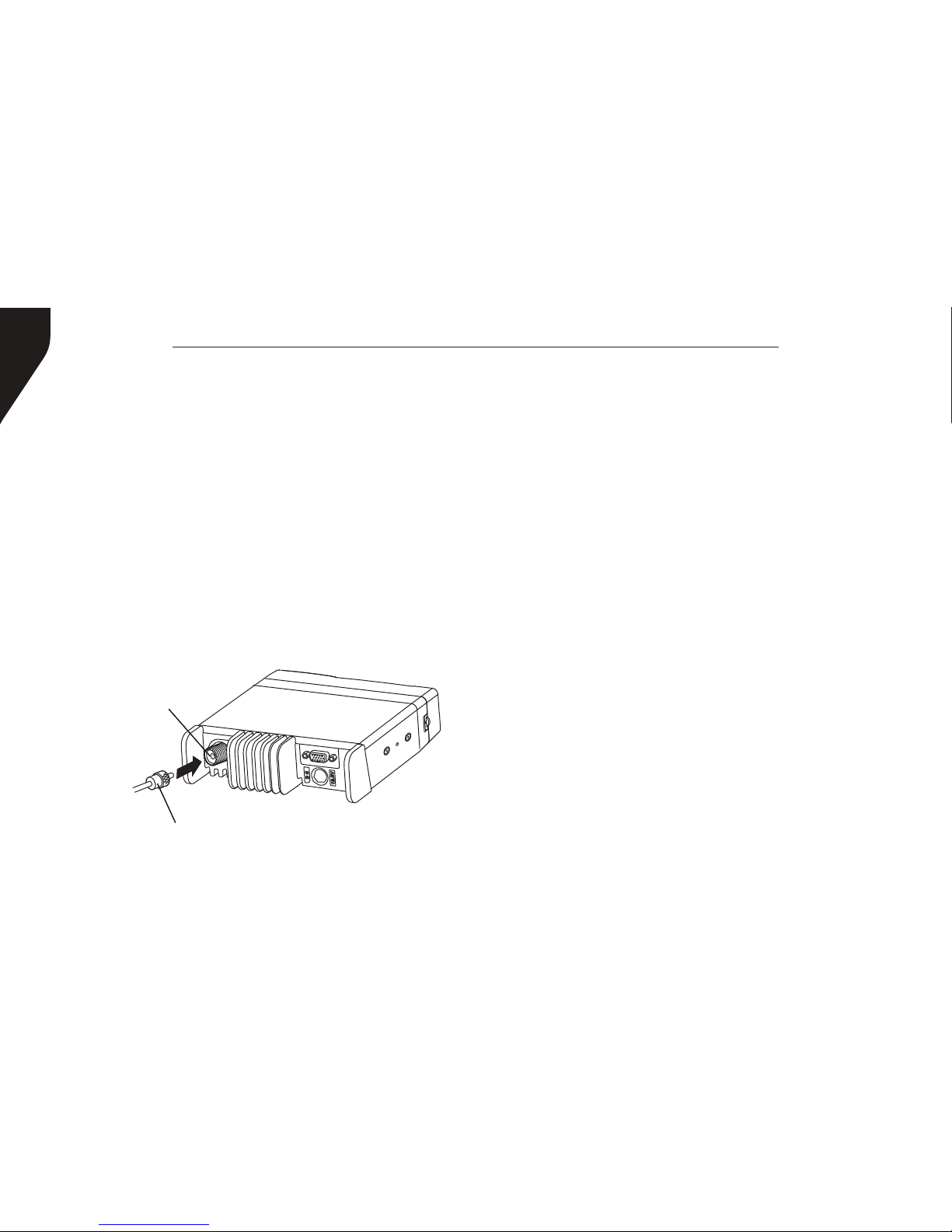
Antenna Connection
Before operating the radio, install an efcient,
well-tuned antenna. The success of your radio
installation will depend largely on the type and
installation of your antenna. The transceiver will
provide excellent results if the antenna system and
radio installation are handled properly. (Figure 8)
Use a 50 Ω impedance antenna and low-loss
coaxial feed line that has a characteristic impedance
of 50 Ω to match the transceiver input impedance.
Coupling the antenna to the transceiver via feed
lines having an impedance other than 50 Ω reduces
the efciency of the antenna system and can cause
interference to nearby broadcast television and
radio receivers, and other electronic equipment.
CAUTION
• Transmitting without first connecting
an antenna or other matched load may
damage the transceiver. Always connect
the antenna to the transceiver before
transmitting.
• All xed stations should be equipped with
Figure 8
Antenna
connector
To
antenna
Feed line connector
Page 13
Copyright © 2015 RCA Communications Systems
13BRM300DTM Professional Digital Two-Way Mobile Radio Instruction Manual
a lightning arrester to reduce the risk of
re, electric shock, and transceiver damage.
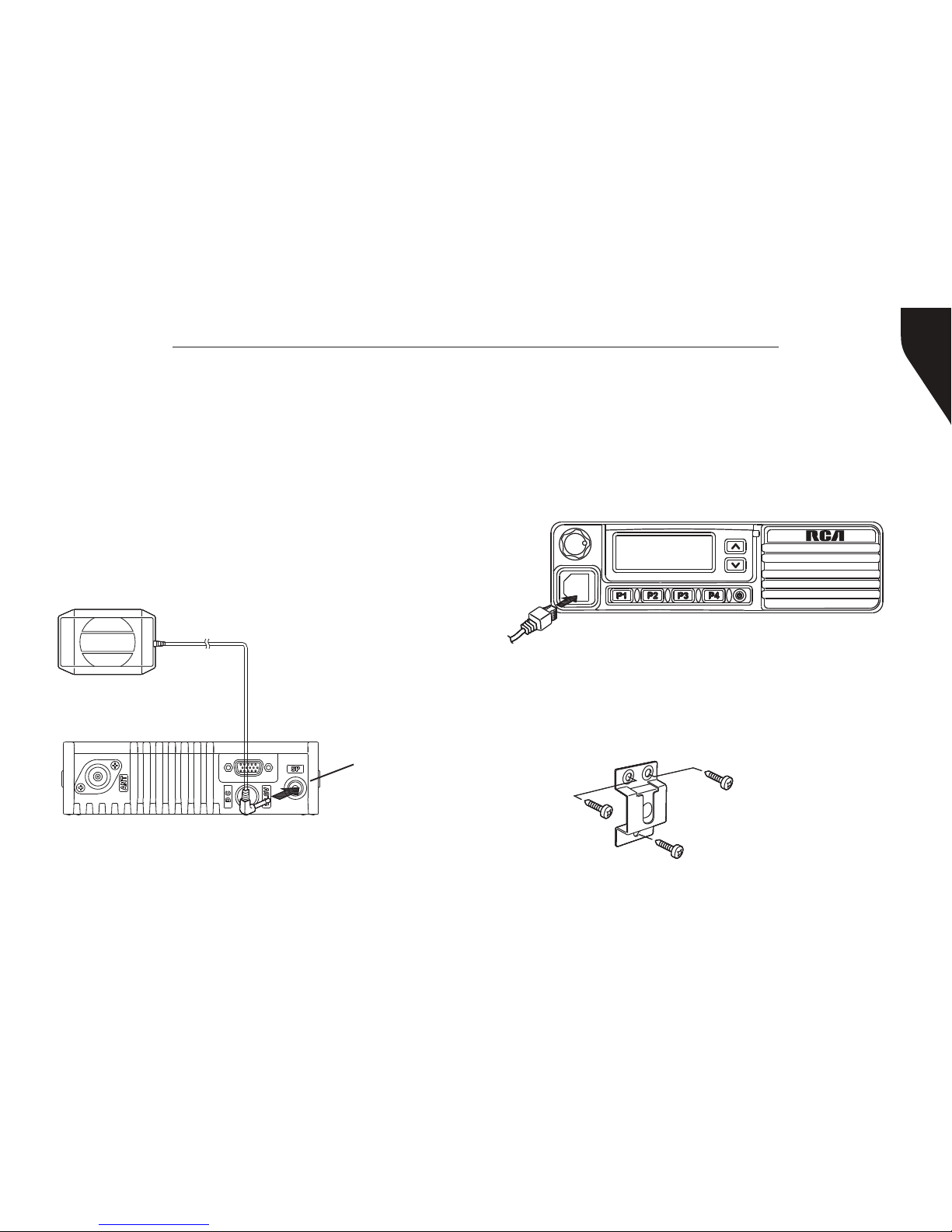
Accessory Connections
External Speaker
If you plan to use an external speaker, choose a
speaker with an impedance of 8 Ω. The external
speaker jack accepts a 1/8” (3.5 mm) mono
(2-conductor) plug. (Figure 9)
Figure 9
External Speaker
External
Speaker
Connection
Microphone Jack
For voice communications, connect a 600 Ω
microphone equipped with an 8-pin modular plug
into the modular socket on the front of the main
unit. Press rmly on the plug until the locking tab
clicks. (Figure 10)
Figure 10
Microphone Hanger
Attach the supplied microphone hanger using
included screws in an easy to access location
that will not interfere with vehicle operation.
(Figure 11)
Figure 11
Microphone hanger
screws - 3mm x 10mm
Page 14
Copyright © 2015 RCA Communications Systems
BRM300DTM Professional Digital Two-Way Mobile Radio Instruction Manual
14
1
5 6 7 8
2 3 4
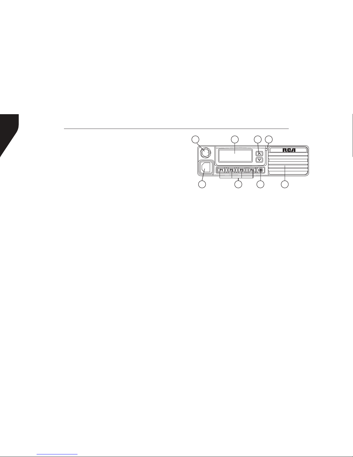
TRANSCEIVER FEATURES
1. Volume Control Knob/Programmable
Button
Turn the Volume Control clockwise to increase
radio volume and counterclockwise to reduce
radio volume. For Programmable Button
information, please see below.
Note: If the radio is programmed with CTCSS/
CDCSS or 2-Tone, MDC1200, Signaling squelch,
nothing will be heard from speaker even if you
turn the Volume Control Knob clockwise to
maximum volume.
2. LCD Display
See “Status Indicators” for display details.
3. Select a Channel/Programmable Buttons
For Programmable Button information, please
see below.
4. LED Indicator - LED Indicator identies radio
status.
• Blinking Red - Radio is scanning, receiving an
emergency transmission or has failed a self-test.
• Solid Red - Radio is transmitting.
• Blinking Green - Radio is powering up.
• Solid Green - Radio is receiving or carrier is
present/busy channel.
• Rapidly Blinking Green - Radio is receiving a
privacy-enabled call or data.
Note: When the LED is solid green, it indicates
the radio detects activity over the air. Due to the
nature of the digital protocol, this activity may or
may not affect the radio’s programmed channel.
Page 15
Copyright © 2015 RCA Communications Systems
15BRM300DTM Professional Digital Two-Way Mobile Radio Instruction Manual
5. Microphone Jack
For voice communications, connect a 600 Ω
microphone equipped with an 8-pin modular
plug into the modular socket on the front of
the main unit. Press rmly on the plug until the
locking tab clicks. (Figure 10)
6. Programmable Buttons P1 - P4
For Programmable Button information, please
see below.
7. On/Off Button
Press the On/Off Button to turn on the radio.
Press and hold down the On/Off Button for
about 1 second to turn off the radio.
8. Internal Speaker
Operational Status Indicators
Your radio indicates its operational status
through the following:
• Display Icons
• Call Icons
• Sent Item Icons
• LED Indicator
• Audio Tones
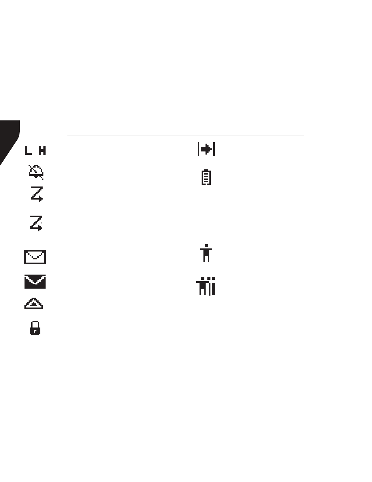
Display Icons
The LCD display shows radio status, text entries,
and menu entries. The following icons will
appear on the radio’s display.
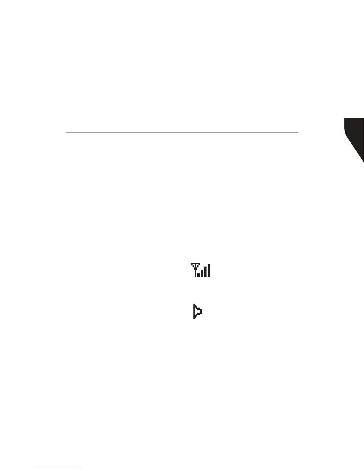
Received Signal Strength Indicator
(RSSI) - The number of bars displayed
represents the radio signal strength and
is only displayed while the radio is in
receiving mode.
Monitor - Selected channel is being
monitored.
Page 16
Copyright © 2015 RCA Communications Systems
BRM300DTM Professional Digital Two-Way Mobile Radio Instruction Manual
16
Power Level - Radio is set at Low
power. Radio is set at High power.
or
Tones Disable - Tones are turned off.
Scan - Scan feature is enabled.
Priority Scan - Radio detects activity on
channel/group designated as Priority 1
(if “•” is blinking) or Priority 2 (if “•” is
steady)
Unread Message - The radio has
unread message(s) in the Inbox.
Inbox Full - The radio’s Inbox is full.
Emergency - Radio is in Emergency mode.
Privacy - The Privacy feature is enabled.
Talkaround - The radio is currently
congured for direct radio to radio
communication.
Battery - The number of bars (0 – 4)
shown indicates the charge remaining in
the battery. Icon blinks when the battery
is low.
Call Icons
The following icons appear on the radio’s
display during a call and in the Contacts list to
indicate ID type.
Private Call - Indicates a Private Call in
progress. In the Contacts list, it indicates
a subscriber alias (name) or ID (number).
Group Call/All Call - Indicates a
Group Call or All Call in progress. In the
Contacts list, it indicates a group alias
(name) or ID (number).
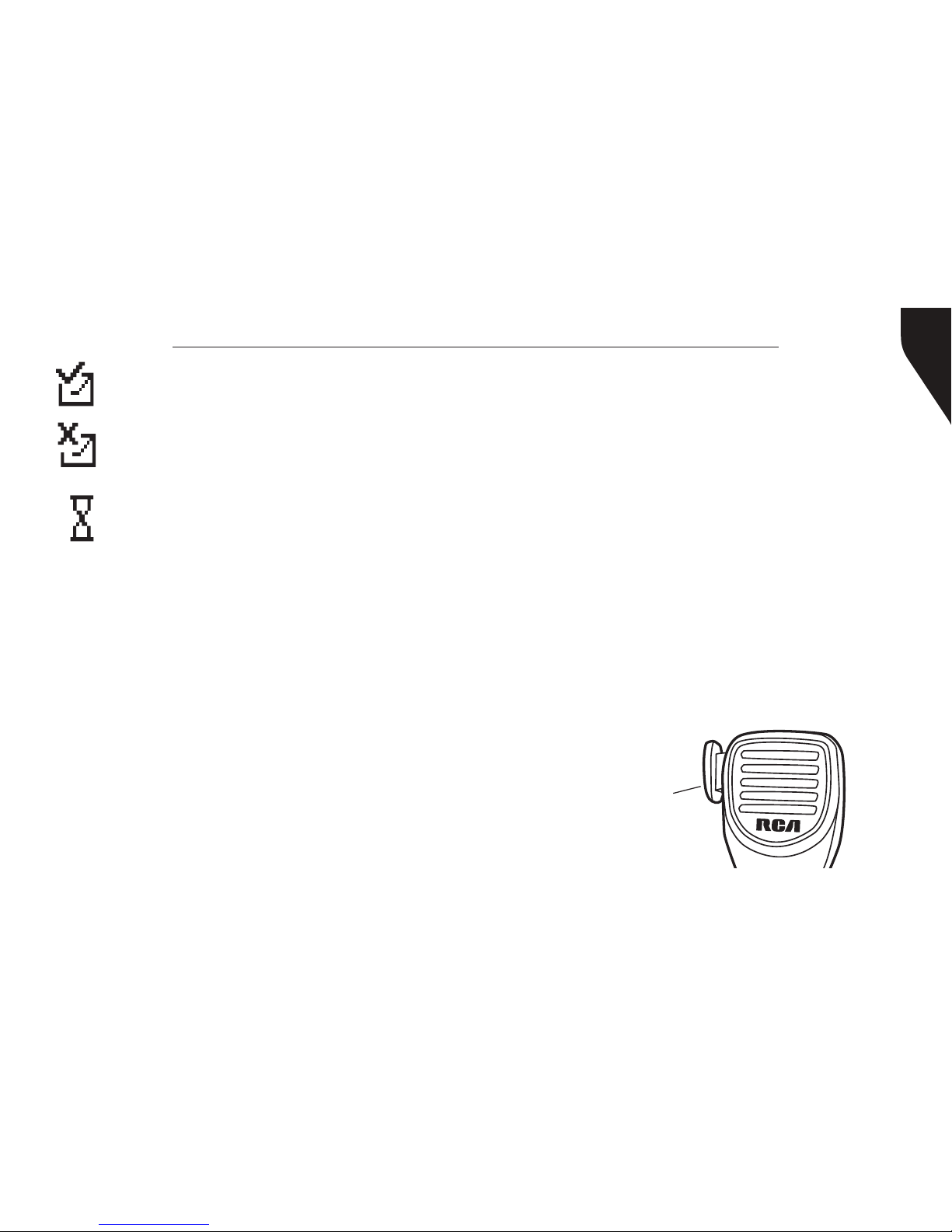
Sent Item Icons
The following icons appear at the top right
corner of the radio’s display in the Sent Items
folder.
Page 17
Copyright © 2015 RCA Communications Systems
17BRM300DTM Professional Digital Two-Way Mobile Radio Instruction Manual
Sent Successfully - The text message
is sent successfully.
Send Failed - The text message cannot
be sent.
In-Progress - The text message to a
group alias or ID is pending transmission.
Audio Tones
Alert tones provide you with audible
indications of the radio’s status or the radio’s
response to data received.
Continuous Tone - A monotone sound.
Sounds continuously until termination.
Periodic Tone - Sounds periodically
depending on the duration set by the radio.
Repetitive Tone - A single tone that repeats
itself until it is terminated by the user.
Momentary Tone - Sounds only once for a
short period of time dened by the radio.
Receiving a Call
If CTCSS/CDCSS, 2-Tone, MDC1200 is set on
the current channel by your RCA dealer, you
can only receive calls with matched signaling. If
CTCSS/CDCSS, 2-Tone, MDC1200 is not set, you
can hear all users on the channel selected.
Transmitting a Call
To transmit a call:
1. Hold the microphone about 2” from your
mouth when speaking and press the [PTT]
(push to talk) button. (Figure 12) The red LED
lights during call.
2. Release [PTT] to return to the receive/listen
(RX) mode.
Figure 12
PTT (Push to
talk) button
Making and Receiving Calls
Page 18

Copyright © 2015 RCA Communications Systems
BRM300DTM Professional Digital Two-Way Mobile Radio Instruction Manual
18
Note on PTT: If the Talk Permit Tone is
enabled, wait until the short alert tone ends
before talking.
During a call, if the Channel Free Indication
feature is enabled on your radio (programmed
by your RCA Communications Systems Dealer),
you will hear a short alert tone the moment the
target radio (the radio that is receiving your call)
releases the PTT button, indicating the channel
is free for you to respond. You will also hear
the Channel Free Indication tone if your call
is interrupted, for example, when the radio
receives an Emergency Call.
Select A Channel
Press [▲] or [▼] to switch between channels.
Channels can be congured as analog or
digital channel. Your radio has features that
are available in both analog and digital mode.
The minor differences in the way each feature
works does not affect the performance of
your radio.
Setting the Squelch Level (Analog)
You can adjust your radio’s squelch level
to lter out unwanted calls with low signal
strength or channels that have a higher than
normal background noise.
Settings: Normal is the default level. Tight
may help to lter out (unwanted) calls and / or
background noise. However, calls from radio
within your system that are in very remote
locations may also be ltered out.
Press the pre-programmed Squelch button to
toggle squelch level between normal and tight.
OR - follow the procedure below to adjust the
Squelch Level through the Menu.
1. Press [Volume Knob (VK)] to access the
menu.
2. Press [▲] or [▼] to navigate to Utilities and
press [VK] to select.
3. Press [▲] or [▼] to navigate to Radio Settings
and press [VK] to select.
Page 19

Copyright © 2015 RCA Communications Systems
19BRM300DTM Professional Digital Two-Way Mobile Radio Instruction Manual
- Long press - Press and hold for the programmed
duration (between 1 seconds and 3.75 seconds).
Programmable Functions:
• All Alert Tones On/Off - Toggles all tones and
alerts on or off.
• Channel Up/Down - Switches between
programmed channels.
• Emergency On/Off - Initiates/cancels an
emergency alarm or call.
• High/Low Transmit Power - Toggles transmit
power level between high and low.
• Lone Worker On/Off - Toggles Lone Worker
feature On or Off, on per channel basis.
• Manual Dial For Private - Enables user to
manually enter a radio ID for a private call.
• Monitor On/Off - Monitors a selected channel
for activity.
• Nuisance Delete - Temporarily removes
an unwanted channel, except the Selected
4. Press [▲] or [▼] to navigate to Squelch and
press [VK]to select.
5. Choose either Tight or Normal and press
[VK] button, screen returns to the previous
menu.
Switching Between Analog/Digital Mode
Each channel in your radio can be programmed
as an analog channel or a digital channel. Use
the Channel Selector Knob to switch between
an analog or a digital channel.
Note: When switching from digital to analog,
some features of the radio become unavailable.
PROGRAMMABLE BUTTONS
Your RCA Communications Systems Dealer can
program the P1, P2, P3, P4, ▲, ▼ and the volume
knob button as shortcuts to radio functions or
preset channels/groups. Several buttons can be
set up with 2 different programmable functions
depending on the duration of a button press:
- Short Press - Press and release quickly.
Page 20

Copyright © 2015 RCA Communications Systems
BRM300DTM Professional Digital Two-Way Mobile Radio Instruction Manual
20
• Surveillance/Covert Mode - Disables screen,
buttons, and LED so the radio remains dark
when operational.
• Tight/Normal Squelch - Toggles between
tight and normal squelch levels.
• Volume Up/Down - Raises and lowers the
volume.
• VOX On/Off - Toggles Voice Activated
Function (VOX) on or off.
• Zone Up/Down - Switches between zones.
Channel, from the scan list. The Selected
Channel refers to the user’s selected zone/
channel combination from which scan is
initiated.
• One Touch Access - Directly initiates a
predened Private or Group Call, a Call Alert
or a Quick Text message.
• Privacy On/Off - Toggles emergency alarm or
call on or off.
• Public Address - Turns public address system
on or off.
• Repeater/Talkaround - Circumvents a
repeater to talk directly to another radio.
• RF Power Switch - Toggles between low and
hi power.
• Scan On/Off - Toggles scan on or off.
• Squelch Level - Toggles between tight, normal
and open.
• Squelch Switch - Toggles squelch on or off.
Page 21

Copyright © 2015 RCA Communications Systems
21BRM300DTM Professional Digital Two-Way Mobile Radio Instruction Manual
Accessing the Programmed Functions
and Radio Menu
There are 2 ways to access various radio functions:
Use a short/long press on a programmable button
OR use the menu options. To access the menu -
• Press the Volume Knob [VK] - Accesses the
menu and conrms menu selection
• Up/Down [▲]/[▼] Buttons - Toggles through
the menu options
• P4 Button [P4] - To go back one menu level, or
return to the previous screen
Note: Your radio will exit the menu after a period
of inactivity and returns to Main Menu.
Keypad/Mic (Optional MM300DK)
The optional keypad microphone also
enables you to access radio features. You
can also use the keypad to enter subscriber
numbers or IDs, and text messages.
Note: Some characters require that you press
a button multiple times. The table shows the
number of times a button needs to be pressed to
generate the required character.
Key 1 2 3 4 5 6 7 8 9 10 11 12 13
1,.?
1 . , ? ! @ & ‘ % - : * #
2abc
A B C 2
3def
D E F 3
4ghi
G H I 4
5jkl
J K L 5
6mno
M N O 6
7pqrs
P Q R S 7
8tuv
T U V 8
9wxyz
W X Y Z 9
0CAPS
0 NOTE: Press to enter “0” and long press to
activate the CAPS lock. Another long press to
turn off the CAPS lock.
*
DEL
* or Del NOTE: Press during text entry to delete
a character.
#
˽
# or Space NOTE: Press during text entry to
insert a space.
Number of Times Button is Pressed
Page 22

Copyright © 2015 RCA Communications Systems
BRM300DTM Professional Digital Two-Way Mobile Radio Instruction Manual
22
Receiving and Responding to a Radio Call
Once the channel, subscriber ID or group ID
is displayed, you can proceed to receive and
respond to calls. To unscramble a privacy-enabled
call, your radio must have the same Privacy Key,
OR ID (programmed by your RCA dealer), as the
transmitting radio (the radio you are receiving the
call from).
Receiving and Responding to a Group Call
To receive a call from a group of users, your radio
must be congured to be part of the group. When
you receive a Group Call:
1. The LED blinks green.
2. The rst line of the display shows the caller alias,
and the RSSI icon. The second line displays the
group alias and the Group Call icon.
3. Press the [PTT] button to respond to the call
and the LED indicator lights up red. Note: If
Talk Permit Function is enabled, wait for the Talk
Permit Tone to nish and then speak clearly into
USING MENU/PROGRAMMED FUNCTIONS
Selecting a Zone
A zone is a group of channels. Your radio has up
to 250 zones with a maximum of 16 channels
per zone.
Press the pre-programmed zone button and
proceed to step 2 OR follow the procedure below.
1. Press [VK] to enter menu, and press ▲/▼ to
nd a Zone and press [VK] to select.
2. The current zone Is displayed an indicated by
a √
3. Press ▲/▼ to nd the zone you want and
press [VK] to select.
4. The display will show the Zone selected for a
moment.
Selecting a Radio Channel, Subscriber ID, or
Group ID Procedure:
If you have multiple zones in your radio, once the
required zone Is displayed, press ▲/▼ to select the
channel, subscriber alias or ID, or group alias or ID.
Page 23

Copyright © 2015 RCA Communications Systems
23BRM300DTM Professional Digital Two-Way Mobile Radio Instruction Manual
the microphone.
4. Release the [PTT] button to listen.
5. If there is no voice activity for a set period of
time, the call ends.
Receiving and Responding to a Private
Call
A Private Call is a call from one individual radio to
another individual radio.
There are two types of Private Calls. The rst type
is when a radio presence check is performed prior
to setting up the call. The second sets up the call
immediately. When you receive a Private Call:
1. The LED blinks green.
2. The rst line of the display shows the subscriber
alias or ID, and the RSSI icon. The second line
displays Private Call and the Private Call icon.
3. Press the [PTT] to respond to the call; the LED
indicator lights up red. Note: If Talk Permit
Function is enabled, wait for the Talk Permit
Tone to nish and then speak clearly into the
microphone.
4. Release the [PTT] button to listen.
5. If there is no voice activity for a predetermined
period of time, the call ends.
Receiving an All Call
An All Call is a call from an individual radio to every
radio on the channel. It is used to make important
announcements requiring the attention of all radio
users. When you receive an All Call:
1. The LED blinks green.
2. The rst line of the display shows the subscriber
alias or ID, and the RSSI icon. The second line
displays All Call and the All Call icon. .
3. Once the All Call ends, the radio returns to the
previous screen before receiving the call.
Note: You cannot respond to an All Call. The
radio stops receiving the All Call if you switch to a
different channel while receiving the call.
Monitoring A Channel (Analog)
Use the Monitor feature to make sure a channel
is clear before transmitting by listening for activity
Page 24

Copyright © 2015 RCA Communications Systems
BRM300DTM Professional Digital Two-Way Mobile Radio Instruction Manual
24
on the channel.
1. Press the pre-programmed Monitor button and
listen for activity. The monitor icon appears on
the display.
2. If you hear activity on the channel the channel is
busy. If you hear “white noise” on the channel
the channel is free.
Making a Radio Call
You can select a channel, subscriber ID, or group
by using:
• The programmable buttons
• The contacts list
• Manual Dial (using contacts list) - This method
is for Private Calls only and is dialed using the
keypad.
Note: Your radio must have the Privacy feature
enabled on the channel to send a privacy-enabled
transmission. Only target radios with the same
Privacy Key OR the same Key Value and Key
ID as your radio will be able to unscramble the
transmission.
Making A Call With Channel Selector
Buttons
Making a Group Call
To make a Group Call, your radio must be
congured to be part of the group.
1. Push the Channel Selector Buttons to select the
channel with the active group alias or ID.
2. Press the [PTT] button to make the call. When
the target radio responds, the LED lights up
green.
3. The display shows the Group icon, group alias
or ID, and transmitting radio alias or ID. Note:
If Talk Permit Function is enabled, wait for the
Talk Permit Tone to nish, then speak clearly
into the microphone.
4. Release the [PTT] button to listen.
5. If there is no voice activity for a predetermined
period of time, the call ends. The radio returns
to the screen you were on prior to initiating
the call.
Page 25

Copyright © 2015 RCA Communications Systems
25BRM300DTM Professional Digital Two-Way Mobile Radio Instruction Manual
Making a Private Call
1. Use the Channel Selector Buttons to select the
channel with the active subscriber alias or ID.
2. Press the [PTT] button to make the call. The
LED lights up solid red. Note: If Talk Permit
Function is enabled, wait for the Talk Permit
Tone to nish and then speak clearly into the
microphone.
3. The rst line displays the subscriber alias or ID.
The second line displays Private Call and the
Private Call icon. Release the [PTT] button to
listen. When the target radio responds, the LED
lights up solid green.
4. If there is no voice activity for a predetermined
period of time, the call ends.
5. The radio returns to the screen last viewed prior
to initiating the call.
Making an All Call
This feature allows you to transmit to all users on a
channel. Your radio must be programmed to allow
you to use this feature.
1. Push the Channel Selector Buttons to select the
channel with the active All Call group alias or ID.
2. Press the [PTT] button to make the call. The
LED lights up solid red and
3. The Display shows the All Call group alias or ID,
and the All Call icon.
Note: Users on the channel cannot respond to
an All Call.
Making a Group or Private Call with the
One Touch Call Button
The One Touch Call feature allows you to make
a Group or Private Call to a predened alias
or ID easily. This feature can be assigned to a
short or long programmable button press. You
can only have one alias or ID assigned to a One
Touch Call button. Your radio can have multiple
One Touch Call buttons programmed.
1. Press the programmed One Touch Call
button to make a Group or Private Call to
Page 26

Copyright © 2015 RCA Communications Systems
BRM300DTM Professional Digital Two-Way Mobile Radio Instruction Manual
26
the predened alias or ID.
2. Press the [PTT] button to make a call. Note:
If Talk Permit Function is enabled, wait for
the Talk Permit Tone to nish, then speak
clearly into the microphone.
3. The display shows the group/subscriber alias
or ID, and the Group/Private Call icon.
4. Release the [PTT] button to listen. When the
target radio responds, the LED blinks green.
5. If there is no voice activity for a predetermined
period of time, the calls end.
6. Radio returns to the screen you were on prior
to initiating the call.
Emergency Operation
An Emergency Alarm is used to indicate a
critical situation. You can initiate an Emergency
at any time on any screen regardless of any
activity on the current channel.
Your radio supports 3 Emergency Alarms:
• Emergency Alarm
• Emergency Alarm with Call
• Emergency Alarm with Voice to Follow
Each alarm has the following types:
• Regular: Radio transmits an alarm signal
and shows audio and/or visual indicators.
• Silent: Radio transmits an alarm signal
without any audio or visual indicators. There
will be no response (call) from the target radio
until you press the PTT button to initiate the
call.
• Silent with Voice: Radio transmits an alarm
signal and is able to receive an incoming call,
without any audio or visual indicators, until
you press the [PTT] button to initiate, or
respond to the call.
Page 27

Copyright © 2015 RCA Communications Systems
27BRM300DTM Professional Digital Two-Way Mobile Radio Instruction Manual
Exiting Emergency Mode
Your radio exits Emergency mode automatically
when any of the following occurs:
• Emergency Alarm acknowledgement is
received (for Emergency Alarm only)
• All retries to send the alarm have been
exhausted
• The Emergency Off button is pressed
• The [PTT] button is pressed
• Your radio is powered off
ADVANCED FEATURES
Public Address
Public Address (PA) is a pre-programmed option
that amplies audio which is then broadcast
through an external speaker.
1. Press the programmed PA button to activate
the PA feature. The LCD shows PA.
2. Speak into the microphone while holding down
the [PTT] to initiate the broadcast. The LCD will
display PA ON. You can adjust the PA volume
via the volume control knob.
Initiating & Responding to Emergency
Alarm
1. To initiate an Emergency Alarm, press the
programmed Emergency button. The LED lights
up solid red.
2. The display shows Sending Alarm, which
alternates with your radio ID. Emergency icon
appears on the Home screen display. When an
Emergency Alarm acknowledgment is received,
an alert tone sounds and the display shows
Emergency Alarm Successful.
3. Depending on the setting selected, you
can press the [PTT] button. OR your radio’s
microphone is automatically activated, allowing
you to communicate with the other radio
without pressing the [PTT] button.
4. To Respond to an Emergency Alarm, press any
button to stop all Emergency Alarm received
indications. Press [PTT] button to initiate a call
with the emergency initiating radio.
Page 28

Copyright © 2015 RCA Communications Systems
BRM300DTM Professional Digital Two-Way Mobile Radio Instruction Manual
28
3. Release the [PTT] key to end the PA broadcast.
The radio will return to the PA mode and the
LCD will display PA. Press PA to disable the PA
feature, and the radio will return to normal
mode.
Note: In PA mode, the radio is unable to transmit
or receive. Optional PA accessories and external
speaker must be installed by your RCA dealer.
Radio Check
If enabled, this feature allows you to determine
if another radio is active in a system without
disturbing the user of that radio. No audible or
visual notication is shown on the target radio.
Note: This feature is only applicable for
subscriber aliases or IDs in digital mode.
Sending a Radio Check
Using the programmed Radio Check button.
1. Press [VK] to access the menu.
2. Press [▲] or [▼] button to navigate to Contacts
and press the [VK] to select.
3. Press [▲] or [▼] to access the required
subscriber alias or ID and press [VK] to select.
Or press [▲] or [▼] button to Manual Dial,
then press [VK], input subscriber ID.
4. Press [▲] or [▼] to Radio Check, then press
[VK] to select. Wait for acknowledgement.
5. The display shows Radio Check: <Subscriber
Alias or ID>, indicating that Radio Check is in
progress. The LED lights up red.
6. If the target radio is active in the system, a tone
sounds and the display briey shows Target
Radio Available. OR - if the target radio is not
active in the system, a tone sounds to indicate
target radio not available.
7. Pressing the [P4] button while the radio is
waiting for acknowledgement and the radio
terminates all retries and exits Radio Check.
ADVANCED FEATURES (Continued)
Page 29

Copyright © 2015 RCA Communications Systems
29BRM300DTM Professional Digital Two-Way Mobile Radio Instruction Manual
Remote Monitor
Use the Remote Monitor feature to turn on the
microphone of a target radio (subscriber alias or
IDs only). No audible or visual indication is given
to the target radio. You can use this feature
to monitor, remotely, any audible activity
surrounding the target radio.
Note: Your radio must be programmed by your
RCA Communications Systems dealer to allow
you to use the Remote Monitor feature.
Initiating Remote Monitor
Use the programmed Remote Monitor button.
1. Press [VK] to access the main menu.
2. Press [▲] or [▼] to navigate to Contacts and
press [VK] to select.
3. Press [▲] or [▼] button to get the required
subscriber alias or ID and press [VK] button to
select. OR - press [▲] or [▼] button to Manual
Dial, then press [VK]. Input subscriber alias or ID
and then press [VK].
4. Press [▲] or [▼] to Remote Monitor and press
[VK] button. Wait for acknowledgement.
5. The screen will display Remote Monitor:
<Subscriber alias or ID>, indicating that Remote
Monitor is in progress. The LED blinks red.
6. The display shows Remote Monitor Successful
OR - Shows Remote Monitor Failed.
7. If successful, the radio will start receiving audio
from the monitored radio for a programmed
duration. Once the timer expires, the radio
sounds an alert tone and the display shows
Remote Monitor Ended. OR - If unsuccessful,
the radio repeats the attempt until the
programmed number of tries expires.
Contacts Settings
Contacts provide “address-book” capabilities on
your radio. Each entry corresponds to an alias or
ID that you can use to initiate a call. Additionally
each entry, depending on context, associates with
one of ve types of calls: Group Call, Private Call,
Page 30

Copyright © 2015 RCA Communications Systems
BRM300DTM Professional Digital Two-Way Mobile Radio Instruction Manual
30
ADVANCED FEATURES (Continued)
5. Release the [PTT] button to listen, when any
user in the group responds, the LED blinks
green. You see Group Call icon, the group
ID, and that user’s ID on your display.
6. If there is no voice activity for a programmed
period of time, the call ends.
Note: If Talk Permit function is enabled, wait
for the Talk Permit Tone to nish and then
speak clearly into the microphone.
Private Call from Contacts
1. Press [VK] to access the menu.
2. Press [▲] or [▼] to navigate to Contacts and
press [VK] to select.
3. Press [▲] or [▼] button to navigate to desired
subscriber alias or ID. OR - Press [▲] or [▼]to
Manual Dial and press [VK]. Use the keypad
to input the subscriber ID.
4. Press the [PTT] to make the call. The rst
line displays the subscriber alias or ID and
the second line displays Private Call and the
All Call, PC Call or Dispatch Call. Each entry within
Contacts displays the following information:
• Call Type
• Call Alias
• Call ID
Note: You can add, delete, or edit contacts from
the Digital Contacts list.
Group Call from Contacts
1. Press [VK] to access the menu.
2. Press [▲] or [▼] button to navigate to
Contacts and press [VK] to select. All entries
are alphabetically sorted.
3. Press [▲] or [▼] button to select the required
group alias or ID.
4. Press [PTT] button to make the call. The
LED lights up solid red. The display shows
Group Call icon, the group alias or ID, and
the Group Call icon.
Page 31

Copyright © 2015 RCA Communications Systems
31BRM300DTM Professional Digital Two-Way Mobile Radio Instruction Manual
5. Press [▲] or [▼] to Call Alert and press [VK]
to select.
6. Press [▲] or [▼] to Private Call and press [VK]
to select.
7. The display shows Turn On. Press [VK] to
enable Call Alert Tones for Private Calls. The
display shows Private Call Tone On. OR - The
display shows Turn Off. Press [VK] to disable
Call Alert Tones for Private Calls. The display
shows Private Call Tone Off.
Activating and Deactivating Call Alert
Tones for Text Messages
Turn on or off the call alert tones for a received
Text Message.
1. Press [VK] to access the main menu.
2. Press [▲] or [▼] to Utilities and press [VK] to
select.
3. Press [▲] or [▼] to Radio Settings and press
[VK] to select.
4. Press [▲] or [▼] to Tone/Alerts and press [VK]
Private Call icon.
5. Release the [PTT] to listen. When the target
radio responds, the LED blinks green and the
display shows the transmitting user’s ID.
6. If there is no voice activity for the programmed
period of time then the call ends.
Note: If Talk Permit function is enabled, wait
for the Talk Permit Tone to nish and then
speak clearly into the microphone.
Call Indicator Settings - Activating And
Deactivating Call Alert Tones for Private
Calls
Turn on or off the call alert tones for a received
Private Call.
1. Press [VK] to access the main menu.
2. Press [▲] or [▼] to Utilities and press to select.
3. Press [▲] or[▼] to Radio Settings and press
[VK] to select.
4. Press [▲] or [▼] to Tone/Alerts and press [VK]
to select.
Page 32

Copyright © 2015 RCA Communications Systems
BRM300DTM Professional Digital Two-Way Mobile Radio Instruction Manual
32
ADVANCED FEATURES (Continued)
to select.
5. Press [▲] or [▼] to Call Alert Tones and press
[VK] to select.
6. Press [▲] or [▼] to Text Message and press
[VK] to select.
7. The current tone is indicated by a √.
8. Press [▲] or [▼] to the preferred tone and
press [VK] to select. The display shows Tone
<Number> Selected and a √ appears left of
the selected tone. OR - Press [▲] or [▼] to
Turn Off and press [VK] to select. The display
shows Text Alert Tones Off and a √ appears
left of Turn Off.
Assigning Alert Tones
You can program your radio to sound one of the
predened ring tones when receiving a Call Alert
or a Text Message from a particular contact.
1. Press [VK] to access the main menu.
2. Press [▲] or [▼]to Contacts and press [VK] to
select. The entries are alphabetically sorted.
3. Press [▲] or [▼] to the required alias or ID and
press [VK] to select.
4. Press [▲] or [▼] to Ring Style and press [VK]
to select.
5. A √ indicates the current selected tone.
6. Press [▲] or [▼] to the required tone and
press [VK] to select.
7. The display shows Tone <Number> Selected
and a √ appears left of the selected tone.
OR - Press [▲] or [▼] to Turn Off and press to
select. The display shows Text Message Tone
Off and a √ appears left of Turn Off.
Call Log Features
Your radio keeps track of all recent outgoing,
answered, and missed Private Calls. Use the
call log feature to view and manage recent
calls. You can Store an ID from the Call
Page 33

Copyright © 2015 RCA Communications Systems
33BRM300DTM Professional Digital Two-Way Mobile Radio Instruction Manual
2. Press [▲] or [▼] button to navigate to [Store].
3. Press [VK].
4. Use the keypad to input a name.
5. Press [VK] to conrm.
6. The display shows Contact Saved.
Note: You can store an ID without an Alias.
Deleting a Call from a Call List
1. While viewing an entry from the Call Log list
press [VK] to select.
2. Press[▲] or [▼] to navigate to [Delete].
3. Press [VK].
4. Press [VK] again to conrm.
5. The display shows Entry Deleted.
6. Press [VK] again to return to main menu.
Call Alert Operation
Call Alert paging enables you to alert a specic
radio user to call you back when they are able
to do so. This feature is applicable for subscriber
Log to Contacts or Delete it. The Call Log
lists are Missed, Answered, and Outgoing.
Note: When you select a Call List and it contains
no entries, the display shows List Empty.
Accessing the Call Log
Use the programmed Remote Monitor button.
1. Press [VK] to access the menu.
2. Press [▲] or [▼] to navigate to Call Log and
press the [VK] to select.
3. Press [▲] or [▼] to navigate to the desired
list and press [VK] to select. The most recent
entry is displayed rst.
4. Use the [▲] or [▼] buttons to scroll through
the list.
5. After locating the desired contact, press
[PTT] to initiate a call.
Storing an Alias or ID from the Missed
Call List
1. While viewing an entry from the Call Log list
press [VK] to select.
Page 34

Copyright © 2015 RCA Communications Systems
BRM300DTM Professional Digital Two-Way Mobile Radio Instruction Manual
34
ADVANCED FEATURES (Continued)
aliases or IDs only and is accessible through the
menu via Contacts or Manual Dial.
Receiving and Responding to a Call Alert
When you receive a Call Alert page, on the
display you see Call Alert that alternates with
the alias or ID of the calling radio.
1. You hear a repetitive tone.
2. Press and release [PTT] button to conrm the
prompt. Or - press [VK] to select ”Ignore?”
and to exit Call Alert.
Making a Call Alert from the Contact List
1. Press [VK] to access the menu.
2. Press [▲] or [▼] to navigate to Contacts and
press [VK] to select.
3. Press [▲] or [▼] to nd the desired subscriber
alias or ID and press [VK] to select. OR - Press
[▲] or [▼] to the Manual Dial option and
press [VK].
4. Use the keypad to input the subscriber ID
and press [VK].
5. Use [▲] or [▼] to nd Call Alert and press
[VK].
6. The display shows Call Alert: <Subscriber Alias
or ID>, indicating that the Call Alert has been
sent.
7. The LED lights up red when your radio is sending
the Call Alert.
8. If the Call Alert acknowledgement is received,
a tone sounds and the display shows
Call Alert successful. OR - If the Call Alert
acknowledgement is not received, a tone
sounds and the display shows Call Alert Failed.
Text Message Features
Your radio is able to receive data such as a text
message from another radio. The maximum text
message length is 138 characters.
Page 35

Copyright © 2015 RCA Communications Systems
35BRM300DTM Professional Digital Two-Way Mobile Radio Instruction Manual
Navigating to Messages
1. Press [VK] to access the menu.
2. Press [▲] or [▼] to navigate to Messages.
Note: Press [P4] button at any time to return
to previous screen.
Receiving a Text Message
When your radio receives a message, the
display shows the alias or ID of the sender and
the Message icon at the far left of the screen.
You can select one of the following options
when receiving a text message:
• Read?
• Read Later
• Delete
Reading a Text Message
1. Press [▲] or [▼] to navigate to [Read?] and
press [VK] to select.
2. Selected message in the Inbox opens. Press
[VK] to return to Home Screen or press
[▲] or [▼] to Read Later or Delete option
screen.
• Select “Read Later” to return to the
screen you were on prior to receiving the
text message.
• Select “Delete” to delete the text
message.
Managing Received Text Messages
Use the Inbox to manage your text messages.
The Inbox is capable of storing a maximum of
50 messages. Your radio supports the following
options for text messages:
• Reply
• Forward
• Delete
• Delete All
Text messages in the Inbox are sorted according
the date they were received.
Viewing a Text Message from the Inbox
1. Press [▲] or [▼] to navigate to Messages and
press [VK] to select.
Page 36

Copyright © 2015 RCA Communications Systems
BRM300DTM Professional Digital Two-Way Mobile Radio Instruction Manual
36
ADVANCED FEATURES (Continued)
2. Press [▲] or [▼] to navigate to Inbox and
press [VK] to select.
3. Press [VK] to select the current message
and press [VK] again to reply, forward or
delete that message. Unread messages are
indicated with an exclamation mark. (!)
Writing and Sending Text Message
1. Press [VK] to access the menu.
2. Press [▲] or [▼] to navigate to Messages and
press [VK] to select.
3. Press [▲] or [▼] to navigate to Write and
press [VK] to select.
4. A blinking cursor appears, use the keypad to
type your message. Press [▲] to move one
space to the left. Press [▼] or [#] to move
one space to the right. Press [*] to delete
unwanted characters.
5. Press [VK] once message is composed.
6. Press [▲] or [▼] to go to the required alias
or ID and press [VK] to select the name. OR
press [▲] or [▼] to access Manual Dial and
press [VK]. Input subscriber ID and press [VK]
to conrm.
7. The radio display shows Text Message:
<Subscriber/Group Alias or ID>, which
conrms your message is being sent.
8. If the message is sent, a tone sounds and the
display shows Message Sent. If the message
is not sent, a low tone sounds and the
display shows Message Send Failed. If the
text message fails to send, the radio returns
you to the Resend option screen.
Sending a Quick Text Message
Your radio stores a maximum of 10 Quick
Text messages as programmed by your RCA
Communications Systems dealer. While Quick
Text messages are predened, you can edit each
message before sending it.
Page 37

Copyright © 2015 RCA Communications Systems
37BRM300DTM Professional Digital Two-Way Mobile Radio Instruction Manual
1. Press [VK] to access the menu.
2. Press [▲] or [▼] to navigate to Messages.
3. Press [▲] or [▼] to Quick Text and press [VK].
4. Press [▲] or [▼] to nd the desired Quick Text
and press [VK] to select.
5. A blinking cursor appears. Use the keypad
to edit the message, if needed. Press
[▲] to move one space to the left. Press
[▼] or [#] to move one space to the right.
Press [*] to delete any unwanted characters.
6. Press [VK] once message is composed.
7. Press [▲] or [▼] to nd the required alias or ID
and press [VK] to select. OR - press [▲] or [▼]
to Manual Dial, press [VK] to select. Input
subscriber ID and press [VK].
8. The display shows Text Message: <Subscriber/
Group Alias or ID>, conrming your message
is being sent.
9. If the message is sent successfully, a tone
sounds and the display shows Message Sent.
OR - If the message is not sent, a low tone
sounds and the display shows Message Send
Failed. If the text message fails to send, the
radio returns you to the Resend option screen.
Note: Your RCA Communications Systems dealer
can program a One Touch Access button to send
a predened Quick Text message to a predened
alias or ID.
Managing Fail-to-Send Text Messages
You can select one of the following options
while at the Resend option screen:
• Resend
• Forward
• Edit
Resending A Text Message
1. Press [VK] to resend the same message to
the same subscriber / group alias or ID.
2. If the message is sent successfully, a tone
sounds and the display shows Message Sent.
Page 38

Copyright © 2015 RCA Communications Systems
BRM300DTM Professional Digital Two-Way Mobile Radio Instruction Manual
38
ADVANCED FEATURES (Continued)
OR - If the message cannot be sent, a low
tone sounds and the display shows Message
Send Failed.
Forwarding a Text Message
1. Once in Messages, press [▲] or [▼] to navigate
to Inbox and press [VK] to select.
2. Press [VK] and [▲] or [▼] to Forward message
and press [VK] to select.
3. Press [▲] or [▼] to nd the required alias or ID
and press [VK]. OR - Press [▲] or [▼] to access
Manual Dial and press [VK]. Input subscriber
ID then press [VK] button.
4. The display shows Text Message: <Subscriber/
Group Alias or ID> conrming your message
is being sent.
5. If the message is sent, a tone sounds and
the display shows Message Sent. OR - If the
message is not sent, a low tone sounds and
the display shows Message Send Failed.
Managing Sent Text Message
Once a message is sent to another radio, it is saved
in Sent Items. The most recent sent text message
is always added to the top of the Sent Items list.
The Sent Items folder is capable of storing
a maximum of thirty (30) last sent message.
When the folder is full, the next sent text
message automatically replaces the oldest text
message in the folder.
Viewing Sent Text Messages
1. Press [▲] or [▼] to navigate to Messages and
press [VK] to select
2. Press [▲] or [▼] to navigate to Sent Items and
press [VK] to select.
3. Press [▲] or [▼] to navigate to the desired
message and press [VK] button.
You can select one of the following options
while viewing a sent text message:
Page 39

Copyright © 2015 RCA Communications Systems
39BRM300DTM Professional Digital Two-Way Mobile Radio Instruction Manual
Deleting All Sent Text Messages from
Sent Items
1. Press [▲] or [▼] to navigate to “Messages”
and press [VK] to select.
2. Press [▲] or [▼] to navigate to “Sent Items”
and press [VK] to select.
3. Press [▲] or [▼] to navigate “Delete All” and
press [VK] to select.
4. The display shows “Delete Message?”, press
[VK] to conrm. The display shows Sent Items
Cleared.
Replying to a Text Message from the
Inbox
1. Press [VK] to access the menu.
2. Press [▲] or [▼] to navigate to Messages and
press [VK] to select.
3. Press [▲] or [▼] to navigate to Inbox and
press [VK] to select.
4. Press [VK] to select current message, and
• Resend
• Forward
• Edit
• Delete
To perform any of the functions:
1. Press [VK] again while viewing message.
2. Press [▲] or [▼] to navigate to Resend, Forward,
Edit or Delete and press [VK] to select.
3. If you select [Resend] or [Edit] and then
[Send], the display will show Text Message:
<Subscriber/Group alias or ID>, conrming
that the same message is being sent to the
same target radio.
4. If the message is sent, a tone sounds and
the display shows Message Sent. OR - If the
message is not sent, a low tone sounds and
the display shows Message Send Failed. The
radio returns to the Resend option screen.
Press [VK] to resend the message to the
same subscriber/group alias or ID.
Page 40

Copyright © 2015 RCA Communications Systems
BRM300DTM Professional Digital Two-Way Mobile Radio Instruction Manual
40
ADVANCED FEATURES (Continued)
press [VK] to select. Press [VK] again to access
the sub-menu and select Reply, Forward or
Delete the message.
5. Press [▲] or [▼] to navigate to Reply and
press [VK] to select.
6. Press [▲] or [▼] to navigate to Write and press
[VK] to select. A blinking cursor appears. Use
the keypad to write your message OR press
[▲] or [▼] to navigate to Quick Text and press
[VK]. After selecting the desired message
press [VK] button. A blinking cursor appears.
Use the keypad to edit your message, if
required.
7. Press [VK] to send and [VK] again to conrm.
8. The display shows Text Message: <Subscriber/
Group Alias or ID>, conrming your message
is being sent.
9. If the message is sent successfully, a tone
sounds and the display shows Message Sent.
If the message cannot be sent, the display
shows Message Send Failed. If the message
fails to send, the radio returns to the Resend
option screen.
Deleting a Text Message from the Inbox
1. Press [VK] to access the menu.
2. Press [▲] or [▼] to navigate to Messages and
press [VK] to select.
3. Press [▲] or [▼] to navigate to Inbox and
press [VK] to select.
4. Press [VK] to select current message, and
press [VK] to select. Press [VK] again to
access the sub-menu to Reply, Forward or
Delete the message.
5. Press [▲] or [▼] to navigate to Delete and
press [VK] to select.
6. Press [▲] or [▼] to navigate to Delete and
press [VK] to select.
7. At Delete Message?, press [▲] or [▼] to
Page 41

Copyright © 2015 RCA Communications Systems
41BRM300DTM Professional Digital Two-Way Mobile Radio Instruction Manual
navigate to Yes and press [VK]. The display
shows Message Deleted.
Note: When you select the Inbox and it
contains no text messages, the display shows
List Empty.
Privacy
If enabled, this feature helps to prevent
eavesdropping by unauthorized users on a
channel by the use of a software based scrambling
solution. The signaling and user identication
portions of a transmission are not scrambled.
Your radio must have privacy enabled on the
channel to send a privacy-enabled transmission,
although it is not required for receiving a privacyenabled transmission. Your radio supports two
types of privacy:
• Basic Privacy
• Enhanced Privacy
Only ONE privacy type above can be assigned to
your radio.
To unscramble a privacy-enabled call or data
transmission, your radio must be programmed
to have the same Privacy Key (for Basic Privacy),
OR the same Key Value and Key ID (for Enhanced
Privacy) as the transmitting radio.
If your radio receives a scrambled call that is of a
different Privacy Key, OR a different Key Value and
Key ID, you will either hear a garbled transmission
(Basic Privacy) or nothing (Enhanced Privacy).
The LED lights up solid green while the radio is
transmitting and blinks green rapidly when the
radio is receiving an ongoing privacy-enabled
transmission.
To make a private call:
1. Press [▲] or [▼] to navigate to Utilities and
press [VK] to select.
2. Press [▲] or [▼] to navigate to Radio Settings
and press [VK] to select.
3. Press [▲] or [▼] to navigate to Privacy and
press [VK] to select.
Page 42

Copyright © 2015 RCA Communications Systems
BRM300DTM Professional Digital Two-Way Mobile Radio Instruction Manual
42
ADVANCED FEATURES (Continued)
4. The display shows Privacy and Turn On. Press
[VK] to enable privacy. The display shows
Privacy On. If the Privacy was already on the
display shows Privacy and Turn Off. Press
[VK] to disable privacy. The display shows
Privacy Off.
Note: This feature is available only in digital mode.
Dual Tone Multi Frequency (DTMF) Analog
The Dual Tone Multi Frequency (DTMF) feature
allows the radio to operate in a radio system with
an interface to telephone or other DTMF based
systems. DTMF Codes can be programmed into
the radio by your RCA Communications Systems
dealer. DTMF receive/transmit feature has four
optional modes with 32 encode groups with up
to 30 characters per group.
To use this feature, your radio must have an access
code, which is system dependent. Please contact
with your RCA Communications Systems dealer
or system administrator for more information.
To initiate a DTMF call.
1. Press and hold PTT button.
2. Enter the desired number.
You can turn off the DTMF tone by disabling
all radio tones and alerts.
Security
The Security Feature allows you to enable
or disable any radio within your system. For
example, you might want to disable a stolen
radio, to preventing a thief from using it, then
enable that radio once recovered. NOTE: The
Disable/Enable feature requires your radio to have
this function enabled. Check with your RCA dealer
or system administrator for more information.
Radio Security enables you to perform the
following functions:
Radio Disable: Radio’s receive / transmit
functions become disabled after the radio
receives the Disable code set by your RCA
Page 43

Copyright © 2015 RCA Communications Systems
43BRM300DTM Professional Digital Two-Way Mobile Radio Instruction Manual
Active code set by your RCA Communications
Systems dealer. OR - Radio Enable can be
initiated through the Menu of your radio.
1. Press [VK] to access the main menu.
2. Press [▲] or [▼] to navigate to Contacts
and press [VK] to select. The entries are
alphabetically sorted.
3. Press [▲] or [▼] to navigate to the desired
subscriber alias or ID and press [VK] to select.
OR - You can press [▲] or [▼] to navigate to
Manual Dial and press [VK], input subscriber
ID and press [VK] to select.
4. Press [▲] or [▼] to navigate to Radio Enable
and press [VK] to select.
5. The display shows Radio Active: <Subscriber
alias or ID> and LED indicator lights red.
6. Wait for acknowledgment.
7. If successful, a tone sounds and the display
shows Radio Enable successfully. If failed, a
tone sounds and the display shows Radio
Enable failed.
Communications Systems dealer.
1. Press [VK] to access the main menu.
2. Press [▲] or [▼] to navigate to Contacts and
press [VK] to select.
3. Press [▲] or [▼] to navigate to the desired
subscriber alias or ID and press [VK] to select.
OR - Press [▲] or [▼] to navigate to Manual
Dial and press [VK], input subscriber ID and
press [VK] to select.
4. Press [▲] or [▼] to navigate to Radio Disable
and press [VK] to select.
5. The display shows Radio Disable: <Subscriber
alias or ID> and LED indicator lights red.
6. Wait for acknowledgment.
7. If successful, a tone sounds and the display
shows Radio Disable successful. If failed, a
tone sounds and the display shows Radio
Disable failed.
Radio Enable: Radio’s receive / transmit
functions become enabled, when the radio is
in Disable status, after the radio receives the
Page 44

Copyright © 2015 RCA Communications Systems
BRM300DTM Professional Digital Two-Way Mobile Radio Instruction Manual
44
ADVANCED FEATURES (Continued)
Scan Lists
Scan lists are created and assigned to individual
channels / groups. The radio scans for voice activity
by cycling through the channel/group sequence
specied in the scan list for the current channel
/ group. Your radio has 250 scan lists with 16
members each. Each scan list supports a mixture
of both analog and digital entries. You can add,
delete, or prioritize channels by editing the scan
lists.
Viewing an Entry in the Scan List
1. Use the Channel Selector Knob to select a
channel programmed with a scan list.
2. Press [VK] to access the menu.
3. Press [▲] or [▼] to navigate to Scan and press
[VK] to select.
4. Press [▲] or [▼] to navigate to View List and
press [VK] to select.
5. Use [▲] or [▼] to view the members on the
scan list.
Note: If set as priority, the Priority icon appears
left of the member’s alias, indicate whether the
member is on a Priority 1 or Priority 2 channel
list. You cannot have multiple Priority 1 or Priority
2 channels in a scan list. There is no priority icon
if priority is set to None.
Scan Instructions and Methods
When a scan is initiated, your radio cycles
through the programmed scan list for the
current channel looking for voice activity. The
LED blinks red and you see the Scan icon on
the display.
There are two ways of initiating scan:
• Manual Scan: Initiate scan manually using the
programmed Scan ON/OFF side button by your
RCA Communications Systems dealer. OR - By
menu function.
• In Manual Scan, radio will detect all channel
/ groups on the programmed scan list.
Page 45

Copyright © 2015 RCA Communications Systems
45BRM300DTM Professional Digital Two-Way Mobile Radio Instruction Manual
• Auto Scan: Your radio automatically starts
scanning when you select a channel / group
that has Auto Scan enabled.
Starting and Stopping Scan
Press the programmed Scan ON/OFF button to
start or stop the Scan. OR - Follow the procedure
below:
1. Use the Channel Selector Knob to select a
channel programmed with a scan list.
2. Press [VK] to access the menu.
3. Press [▲] or [▼] to navigate to Scan and press
[VK] to select.
4. The display shows Turn Off if scan is disabled
or the display shows Turn on if scan is enabled.
5. Press [VK] to select.
6. The LED blinks red and the Scan icon is
displayed when Scan is enabled. The LED turns
off and the Scan icon disappears when Scan
is disabled.
Responding to a Scan
During scanning, your radio stops on any
channel / group where activity is detected. After
the transmission is over the radio remains on the
active channel for a programmed time period
known as “hang time”.
1. Press the PTT button during “hang time” to
respond to the call. The LED lights up red.
2. Release PTT button to listen.
Note: If you do not respond within the “hang
time” period, the radio continues scanning other
channels / groups.
Deleting a Nuisance Channel
If a channel continually generates unwanted
calls or noise (termed a “nuisance” channel),
you can temporarily remove the unwanted
channel from the scan list.
Note: This capability does not apply to the
Page 46

Copyright © 2015 RCA Communications Systems
BRM300DTM Professional Digital Two-Way Mobile Radio Instruction Manual
46
ADVANCED FEATURES (Continued)
channel designated as the Selected Channel.
This feature is not accessible through the
menu.
1. When your radio stops on an unwanted or
nuisance channel, press the programmed
Nuisance Channel Delete button until you
hear a tone.
2. Release the Nuisance Channel Delete button.
The nuisance channel is deleted.
Restoring a Nuisance Channel
To restore the deleted nuisance channel, power
the radio off and back on again. OR - Press Stop
and Start to restart a scan via the programmed
Scan button.
Utilities
Keypad Locked or Unlocked (For use
with optional MM300DK Keypad/Mic.)
You can lock your radio’s keypad to avoid an
inadvertent key entry.
1. Press [VK] to access the main menu.
2. Press [▲] or [▼] to navigate to Utilities and
press [VK] to select.
3. Press [▲] or [▼] to navigate to Radio Settings
and press [VK] to select.
4. Press [▲] or [▼] to navigate to Keypad Lock
and press [VK] to select.
5. The display shows Keypad Locked and
returns to the home screen.
To unlock the keypad, press [VK] button then
press [*] button. The display shows Keypad
Unlocked and returns to the home screen.
Keypad Tones On or Off (For use with
optional MM300DK Keypad/Mic.)
You can enable and disable keypad tones if
needed.
1. Press [VK] to access the main menu.
2. Press [▲] or [▼] to navigate to Utilities and
press [VK] to select.
3. Press [▲] or [▼] to navigate to Radio Settings
Page 47

Copyright © 2015 RCA Communications Systems
47BRM300DTM Professional Digital Two-Way Mobile Radio Instruction Manual
and press [VK] to select.
4. Press [▲] or [▼] to navigate to Tone/Alerts
and press [VK] to select.
5. Press [▲] or [▼] to navigate to Keypad Tones
and press [VK] to select.
6. If the display shows Turn On, Press [VK]
to enable the keypad tones. If the display
shows Turn Off press [VK] to disable the
keypad tones.
Setting the Power Level
You can customize your radio’s power setting
to high or low for each channel.
Settings:
Press the programmed Power Level button to
toggle transmits power level between high and
low. OR - Follow the procedure below to adjust
the Power Level through the Menu.
1. Press [VK] to access the main menu.
2. Press [▲] or [▼] to navigate to Utilities and
press [VK] to select.
3. Press [▲] or [▼] to navigate to Radio Settings
and press [VK] to select.
4. Press [▲] or [▼] to navigate to Power and
press [VK] button.
5. Change your current setting as prompted on
the display and press [VK] to select.
Press the [P4] button to return to the Home
screen. The display shows the Power Level icon.
Voice Operating Transmission (VOX)
Feature On / Off
This feature allows you to initiate a handsfree voice activated call on a programmed
channel. The radio automatically transmits,
for a programmed period, whenever the
microphone on the VOX-capable accessory
detects a voice.
Note: This feature must be programmed by
your RCA dealer to use this function.
To begin using VOX: Press the programmed
VOX button to toggle the feature on or off.
Page 48

Copyright © 2015 RCA Communications Systems
BRM300DTM Professional Digital Two-Way Mobile Radio Instruction Manual
48
ADVANCED FEATURES (Continued)
OR - Follow the procedure below to activate or
deactivate VOX through the Menu.
1. Press [VK] to access the menu.
2. Press [▲] or [▼] to navigate to Utilities and press
[VK] to select.
3. Press [▲] or [▼] to navigate to Radio Settings
and press [VK] to select.
4. Press [▲] or [▼] to navigate to VOX and press
[VK] to select.
5. If the display shows VOX On, press [VK] to
disable VOX. The display will change to VOX
Off. OR - If the display shows VOX Off, press
[VK] to enable VOX and display shows VOX On.
Note: Pressing the PTT button during radio
operation will disable VOX.
Controlling the Display Backlight
You can enable or disable the radio’s display
backlight. The setting also affects the Menu
navigation buttons and keypad backlighting
accordingly. Press the programmed Backlight
button to toggle the backlight settings. OR -
1. Press [VK] to access the main menu.
2. Press [▲] or [▼] to navigate to Utilities and press
[VK] to select.
3. Press [▲] or [▼] to navigate to Radio Settings
and press [VK] to select.
4. Press [▲] or [▼] to navigate to Backlight and
press [VK] button.
5. If the display shows “Auto On”. Press
[VK] to enable the display backlight and
the display shows “Backlight Auto On”.
OR - If the display shows “Turn Off” press
[VK] to disable the display backlight and the
display shows “Backlight Turn Off”.
Note: The display backlight and keypad backlight
are automatically turned off if the LED indicator
is disabled.
Talkaround
Page 49

Copyright © 2015 RCA Communications Systems
49BRM300DTM Professional Digital Two-Way Mobile Radio Instruction Manual
This feature toggles between repeater and
talkaround (direct) mode. If you are using a
repeater and your repeater is not operating
or you are out of range, you can continue to
communicate with other radios within your group
through “Talkaround”.
Press the programmed Repeater / Talkaround
button to toggle between talkaround and
repeater modes. OR -
1. Press [VK] to access the main menu.
2. Press [▲] or [▼] to navigate to Utilities and press
[VK] to select.
3. Press [▲] or [▼] to navigate to Radio Settings
and press [VK] to select.
4. Press [▲] or [▼] to navigate to Talkaround and
press [VK] to select or [P4] to cancel.
5. After confirmation, the display shows
“Talkaround On” OR “Talkaround Off”
6. Press or wait the presetting time to exit the
menu.
7. The Talkaround setting is retained even after
powering down.
Radio Tones/Alerts On or Off
You can enable and disable all radio tones and
alerts (except for the incoming Emergency alert
tone) if needed. Press the programmed All Tones/
Alerts button to toggle all tones on or off.
1. Press [VK] to access the main menu.
2. Press [▲] or [▼] to navigate to Utilities and press
[VK] to select.
3. Press [▲] or [▼] to navigate to Radio Settings
and press [VK] to select.
4. Press [▲] or [▼] to navigate to Tones / Alerts
and press [VK] to select.
5. Press [▲] or [▼] to navigate to All Tones and
press [VK] to select.
6. If the display shows Turn On press [VK] to
enable all tones and alerts and the display
shows All Tones On. If the display shows Turn
Off press [VK] to disable all tones and alerts and
Page 50

Copyright © 2015 RCA Communications Systems
BRM300DTM Professional Digital Two-Way Mobile Radio Instruction Manual
50
ADVANCED FEATURES (Continued)
the display shows All Tones Off.
LED Indicator On or Off
You can enable and disable the LED Indicator
if needed.
1. Press [VK] to access the main menu.
2. Press [▲] or [▼] to navigate to Utilities and
press [VK] to select.
3. Press [▲] or [▼] to navigate to Radio Settings
and press [VK] to select.
4. Press [▲] or [▼]to navigate to LED Indicator
and press [VK] button.
5. If the display shows Turn On, press [VK] to
enable the LED Indicator and the display
shows All LEDs On. If the display shows Turn
Off, press [VK] to disable the LED Indicator
and the display shows All LEDs Off.
Note: The display backlight, buttons and
keypad backlight are automatically turned off
if the LED indicator is disabled.
Turning the Introduction Screen On/Off
You can enable and disable the Introduction
Screen if needed.
1. Press [VK] to access the main menu.
2. Press [▲] or [▼] to navigate to Utilities and
press [VK] to select.
3. Press [▲] or [▼] to navigate to Radio Settings
and press [VK] to select.
4. Press [▲] or [▼] to navigate to Intro Screen
and press [VK] to select.
5. If The display shows Turn On, press [VK]
to enable the Introduction Screen and the
display shows Intro Screen On. If the display
shows Turn Off, press [VK] to disable the
Introduction Screen and the display shows
Page 51

Copyright © 2015 RCA Communications Systems
51BRM300DTM Professional Digital Two-Way Mobile Radio Instruction Manual
CARE AND CLEANING
• Do not place anything on top of the radio
that will prevent heat dissipation.
• Be sure radio is powered off before cleaning.
• Do not place the radio in a dusty or dirty
environment.
• Clean the radio with a lint-free/non woven
fabric moistened with clean water and/or
a mild dish washing liquid to remove dirt,
grease, and dust.
• Avoid subjecting the radio to corrosives,
solvents or spirits.
• Make sure the radio is completely dry before
use.
Intro Screen Off.
Accessing General Radio Information
Your radio contains information on the following:
• Radio ID
• Software version
• Codeplug Version
Checking the Radio ID
1. Press [VK] to access the main menu.
2. Press [▲] or [▼] to navigate to Utilities and
press [VK] to select.
3. Press [▲] or [▼] to navigate to Radio Info and
press [VK] to select.
4. Press [▲] or [▼] to navigate to My Number, or
Firmware Vr., or CP Vr. and press [VK]button.
5. The display shows radio ID, the current
rmware or the codeplug version.
Page 52

Copyright © 2015 RCA Communications Systems
BRM300DTM Professional Digital Two-Way Mobile Radio Instruction Manual
52
Symptom Solution
Radio will not power on
1. Check the power connections to make sure they have a solid
connection.
2. Check for (one or more) blown fuse(s)
Radio is on, but you cannot
hear voice transmissions or
they are not very loud
1. Turn the volume control knob to maximum volume.
2. Make sure you are within communication range..
You cannot log on to the
system
Check the antenna connection to make sure it has a solid
connection.
Cannot talk to or hear from
group members
1. Make sure you are within communication range.
2. Check the squelch level
3. Digital: Be sure the CC, ID, Time Slot is set correctly
4. Analog: Be sure you’re using the same channel and/or have
the same CTCSS/CDCSS settings as your group members.
Transmissions from nongroup members are heard
Analog: Change CTCSS/DCS tone and make sure all other
radios in your group are using the same CTCSS/DCS tone
TROUBLESHOOTING
Page 53

Copyright © 2015 RCA Communications Systems
53BRM300DTM Professional Digital Two-Way Mobile Radio Instruction Manual
Symptom Solution
Communication range is
small
1. Make sure antenna is not damaged and has a solid
connection
2. Check the squelch level
Unable to transmit
1. Make sure the PTT button has been pressed completely
2. Transmitting frequency has not been set on the radio
3. The radio has been killed remotely
Noise is too loud
1. Check squelch level
2. Beyond efcient communication range
Buttons will not work Restart the radio
Radio cannot lock out Restart the radio
No display Restart the radio
Page 54

Copyright © 2015 RCA Communications Systems
BRM300DTM Professional Digital Two-Way Mobile Radio Instruction Manual
54
Optional Accessories
Note: Only the use of Genuine RCA accessories will guarantee compatibility and maximum performance of your radios.
Speaker/Microphone - For voice communication. Includes
15’ cord.
MM300D
Keypad Speaker/Microphone - For voice and text
communication. Includes 15’ cord.
MM300DK
Page 55

Copyright © 2015 RCA Communications Systems
55BRM300DTM Professional Digital Two-Way Mobile Radio Instruction Manual
Optional Accessories continued
Desktop Microphone - Perfect for base station users,
unit includes large buttons for easy operation and comes
equipped with a monitoring key and lock.
DMM1250
Base Station Conversion Kit - Converts mobile unit into a
base station. Includes housing and power supply.
BSC300D PKG
Page 56

Copyright © 2015 RCA Communications Systems
BRM300DTM Professional Digital Two-Way Mobile Radio Instruction Manual
56
FCC Caution:
Any changes or modifications not expressly
approved by the party responsible for compliance
could void the user’s authority to operate the
equipment. This device complies with part 15
of the FCC Rules. Operation is subject to the
following two conditions: (1) This device may not
cause harmful interference, and (2) this device
must accept any interference received, including
interference that may cause undesired operation.
This equipment has been tested and found
to comply with the limits for a Class B digital
device, pursuant to part 15 of the FCC Rules.
These limits are designed to provide reasonable
protection against harmful interference in a
residential installation. This equipment generates
uses and can radiate radio frequency energy and,
if not installed and used in accordance with the
instructions, may cause harmful interference to
radio communications.
However, there is no guarantee that interference
will not occur in a particular installation. If this
equipment does cause harmful interference
to radio or television reception, which can be
determined by turning the equipment off and
on, the user is encouraged to try to correct the
interference by one or more of the following
measures:
• Reorient or relocate the receiving antenna.
• Increase the separation between the
equipment and receiver.
• Connect the equipment into an outlet on
a circuit different from that to which the
receiver is connected.
• Consult the dealer or an experienced radio/TV
technician for help.
RF Exposure Compliance and Control
Guidelines and Operating Instructions
To control your exposure and ensure compliance
with the occupational/controlled environment
exposure limits always adhere to the following
procedures.
Guidelines: Do not remove the RF Exposure Label
from the device.
Page 57

Copyright © 2015 RCA Communications Systems
57BRM300DTM Professional Digital Two-Way Mobile Radio Instruction Manual
User awareness instructions should accompany
device when transferred to other users.
Do not use this device if the operational
requirements described herein are not met.
Operating Instructions: Transmit no more than the
rated duty factor of 50% of the time. To transmit
(talk), push the Push-To-Talk (PTT) button. To receive
calls, release the PTT button.
Transmitting 50% of the time or less is important
because this radio generates measurable RF energy
exposure only when transmitting (in terms of
measuring for standards compliance). Hold the
radio in a vertical position in front of face with
the microphone (and the other parts of the radio,
including the antenna) at least one inch (2.5 cm)
away from the nose. Keeping the radio at the
proper distance is important because RF exposures
decrease with distance from the antenna. Antenna
should be kept away from eyes.
When worn on the body, always place the radio
in a approved clip, holder, holster, case, or body
harness for this product.
Using approved body-worn accessories is important
because the use of or other manufacturer’s nonapproved accessories may result in exposure levels,
which exceed the FCC’s occupational/controlled
environment RF exposure limits.
If you are not using a body-worn accessory and are
not using the radio in the intended use position
in front of the face, then ensure the antenna and
the radio are kept at least one inch (2.5 cm) from
the body when transmitting. Keeping the radio
at the proper distance is important because RF
exposures decrease with increasing distance from
the antenna.
Use only RCA Communications Systems approved,
supplied or replacement antennas, batteries, and
accessories. Use of non-approved antennas,
batteries, and accessories may exceed the FCC RF
exposure guidelines.
WARRANTY STATEMENT
RCA Communications Systems warrants each new
radio product it supplies to be free from defects in
material and workmanship under normal use and
Page 58

Copyright © 2015 RCA Communications Systems
BRM300DTM Professional Digital Two-Way Mobile Radio Instruction Manual
58
service for the time period listed below, provided
that the user has complied with the requirements
stated herein.
The warranty period begins on the date of purchase
from an Authorized RCA Communications Systems
Sales and Service Outlet. This warranty is offered
to the original end user and is not assignable or
transferable. RCA Communications Systems is
not responsible for any ancillary equipment which
is attached to or used in conjunction with RCA
Communications Systems products.
RCA Communications Systems offers to the
original end user a Three (3) Year Limited Warranty
on the RCA BRM300DTM Mobile Radio. The
MM300D Mobile Microphone is covered under a
One (1) Year Limited Warranty.
During this period, if the product fails to function
under normal use because of manufacturing
defect(s) or workmanship, it should be returned
to the Authorized RCA Communications Systems
Sales and Service Outlet from which it was
purchased. The Sales and Service Outlet will repair
the product to full operating specications or
replace the product with a new product of the
same make and model. The user is responsible for
all charges incurred in returning the product to the
Authorized RCA Communications Systems Sales
and Service Outlet. RCA Communications Systems
will be responsible for all charges in returning the
product to the end user via standard ground
shipping service.
RCA Communications Systems shall have no
obligation to repair or replace the product, if there
is damage as a result of normal wear and tear
or if the damage is caused in whole or in part
by catastrophe, fault or negligence of the user,
improper or unauthorized alterations or repairs to
the product, incorrect wiring, use of the product
in a manner for which it was not designed, or by
causes external to the product. The radio equipment
warranty does not cover physical or liquid damage,
which includes, but is not limited to, liquid damage,
damaged screen, deep scratches, bent or broken
body or frame, damaged channel or volume
controls, damaged antenna, or accessory ports.
Page 59

Copyright © 2015 RCA Communications Systems
59BRM300DTM Professional Digital Two-Way Mobile Radio Instruction Manual
This warranty is void if the product serial number is
altered, defaced or removed.
THE EXPRESS WARRANTIES CONTAINED HEREIN
ARE IN LIEU OF ALL OTHER WARRANTIES,
EITHER EXPRESSED OR IMPLIED OR STATUTORY,
INCLUDING, WITHOUT LIMITATION, ANY
WARRANTY OF MERCHANTABILITY OR FITNESS
FOR A PARTICULAR PURPOSE.
FOR ANY PRODUCT WHICH DOES NOT COMPLY
WITH THE WARRANTY SPECIFIED, THE SOLE
REMEDY WILL BE REPAIR OR REPLACEMENT. IN NO
EVENT WILL RCA COMMUNICATIONS SYSTEMS
BE LIABLE TO THE BUYER OR ITS CUSTOMERS
FOR ANY DAMAGES, INCLUDING ANY SPECIAL,
INCIDENTAL, INDIRECT OR CONSEQUENTIAL
DAMAGES, OR THE LOSS OF PROFIT, REVENUE OR
DATA ARISING OUT OF THE USE OR THE INABILITY
TO USE THE PRODUCT.
RCA Communications Systems endeavors to
achieve the accuracy and completeness of this
manual, but is not liable for possible omissions and/
or printing mistakes.
All the above specications and design are subject
to change without prior notice.
All the reproduction and translation of this manual
without authorization is prohibited.
All specications and designs are subject to change
without notice due to continuous development.
No part of this manual may be copied, reproduced,
translated, stored in a retrieval system, distributed,
or transmitted in any form or by any means,
electronic or mechanical, for any purpose without
the expressed, written permission from RCA
Communications Systems.
The end-user of any two-way radio is solely
responsible for obtaining any license or
other authorizations required by the Federal
Communications Commission (FCC). For further
information visit www.fcc.gov or call 1-888-CALLFCC (1-888-225-5322).
Page 60

Copyright © 2015 RCA Communications Systems
BRM300DTM Professional Digital Two-Way Mobile Radio Instruction Manual
60
© 2015 RCA Communications Systems. All rights reserved.
Communications Systems
www.RCACommunicationsSystems.com
For Sales, Warranty and Customer Support please contact:
Discount Two-Way Radio Corporation – North American Distributor
555 W Victoria Street
Rancho Dominguez, CA 90220
Phone: 310-224-5100 / Fax: 310-224-5101
www.DiscountTwo-WayRadio.com
 Loading...