

Page 1
For qualified service personne_ only
Version 1,,0 for 2012
Mode_,
50LB45RQ
Made for Today.
www.rca.com
Page 2
Revision No. Revision Date Page Description
1 May, 2012 All Initial Release
Version 1.0
Page 3
1.1 Basic Specifications
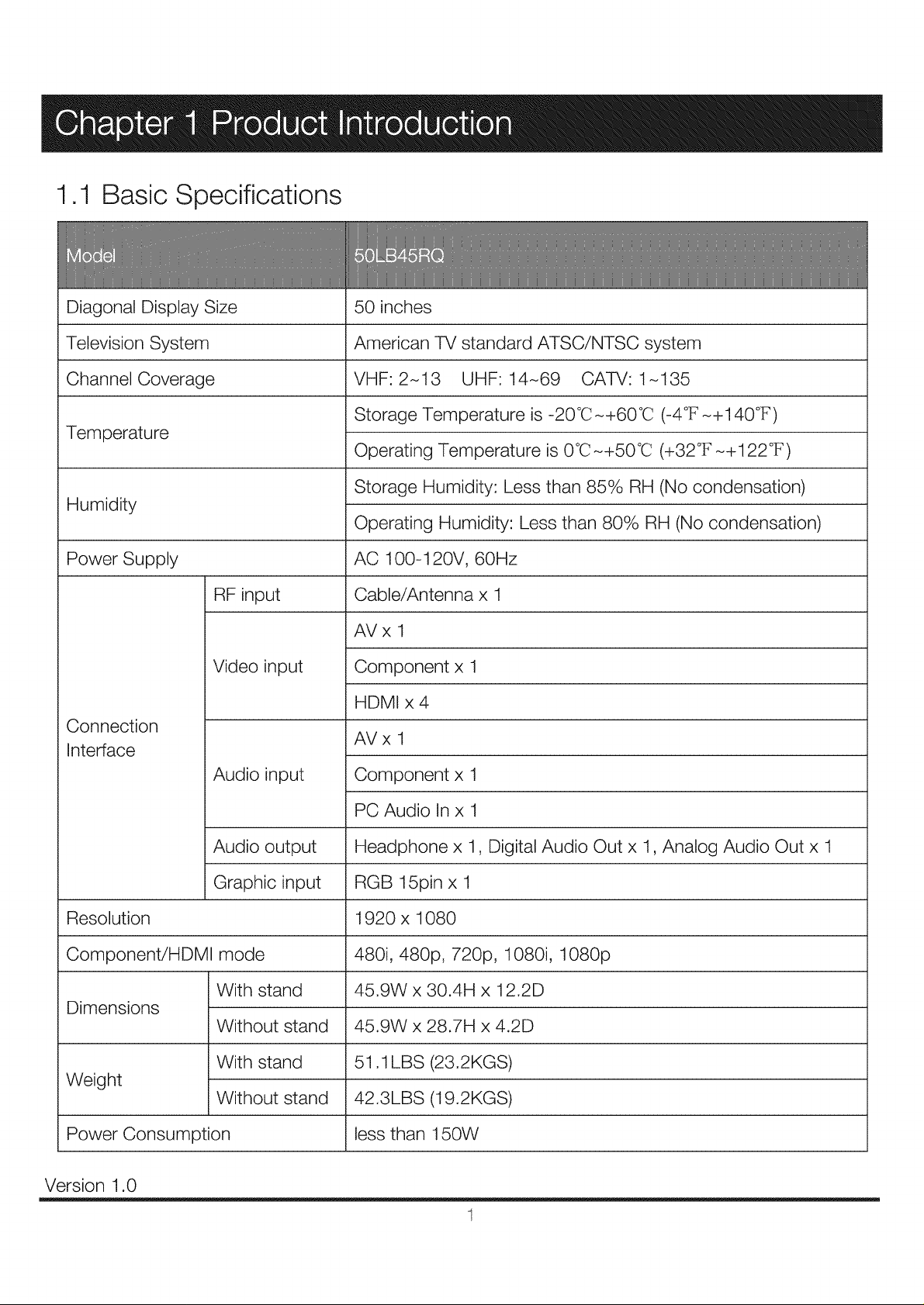
Diagonal Display Size
Television System
Channel Coverage
Temperature
Humidity
Power Supply
RF input
Video input
Connection
Interface
Audio input
50 inches
American TV standard ATSC/NTSC system
VHF:2-13 UHF:14-69 CAW:1-135
Storage Temperature is -20°C-+60°C (-4°F-+140°F)
Operating Temperature is 0°C-+50°C (+32°F-+122°F)
Storage Humidity: Less than 85% RH (No condensation)
Operating Humidity: Less than 80% RH (No condensation)
AC 100-120V, 60Hz
Cable/Antenna x 1
AVx 1
Component x 1
HDMI x 4
AVx 1
Component x 1
Resolution
Component/HDMI mode
Dimensions
Weight
Power Consumption
Version 1.0
Audio output
Graphic input
With stand
Without stand
With stand
Without stand
PC Audio In x 1
Headphone x 1, Digital Audio Out x 1, Analog Audio Out x 1
RGB 15pin x 1
1920 x 1080
480i, 480p, 720p, 1080i, 1080p
45.9W x 30.4H x 12.2D
45.9W x 28.7H x 4.2D
51.1 LBS (23.2KGS)
42.3LBS (19.2KGS)
less than 150W
1
Page 4
1,2 Product Function
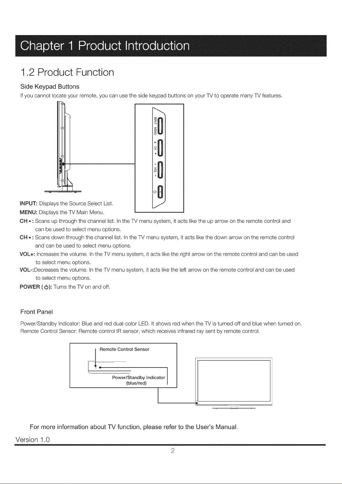
Side Keypad Buttons
If you cannot locate your remote, you can use the side keypad buttons on your TV to operate many TV features.
INPUT: Displays the Source Select List.
MENU: Displays the TV Main Menu.
OH ,, : Scans up through the channel list. In the TV menu system, it acts like the up arrow on the remote control and
can be used to select menu options.
OH ,, : Scans down through the channel list. In the TV menu system, it acts like the down arrow on the remote control
and can be used to select menu options.
VOL+: Increases the volume. In the TV menu system, it acts like the right arrow on the remote control and can be used
to select menu options.
VOL-:Decreases the volume. In the TV menu system, it acts like the left arrow on the remote control and can be used
to select menu options.
POWER (O): Turns the TV on and off.
Front Panel
Power/Standby Indicator: Blue and red dual-color LED.Itshows red when the TV isturned off and blue when turned on.
Remote Control Sensor: Remote control IRsensor, which receives infrared ray sent by remote control.
_! Remote Control Sensor
Power/Standby Indicator
(blue/red)
For more information about TV function, please refer to the User's Manual.
Version 1.0
2
Page 5
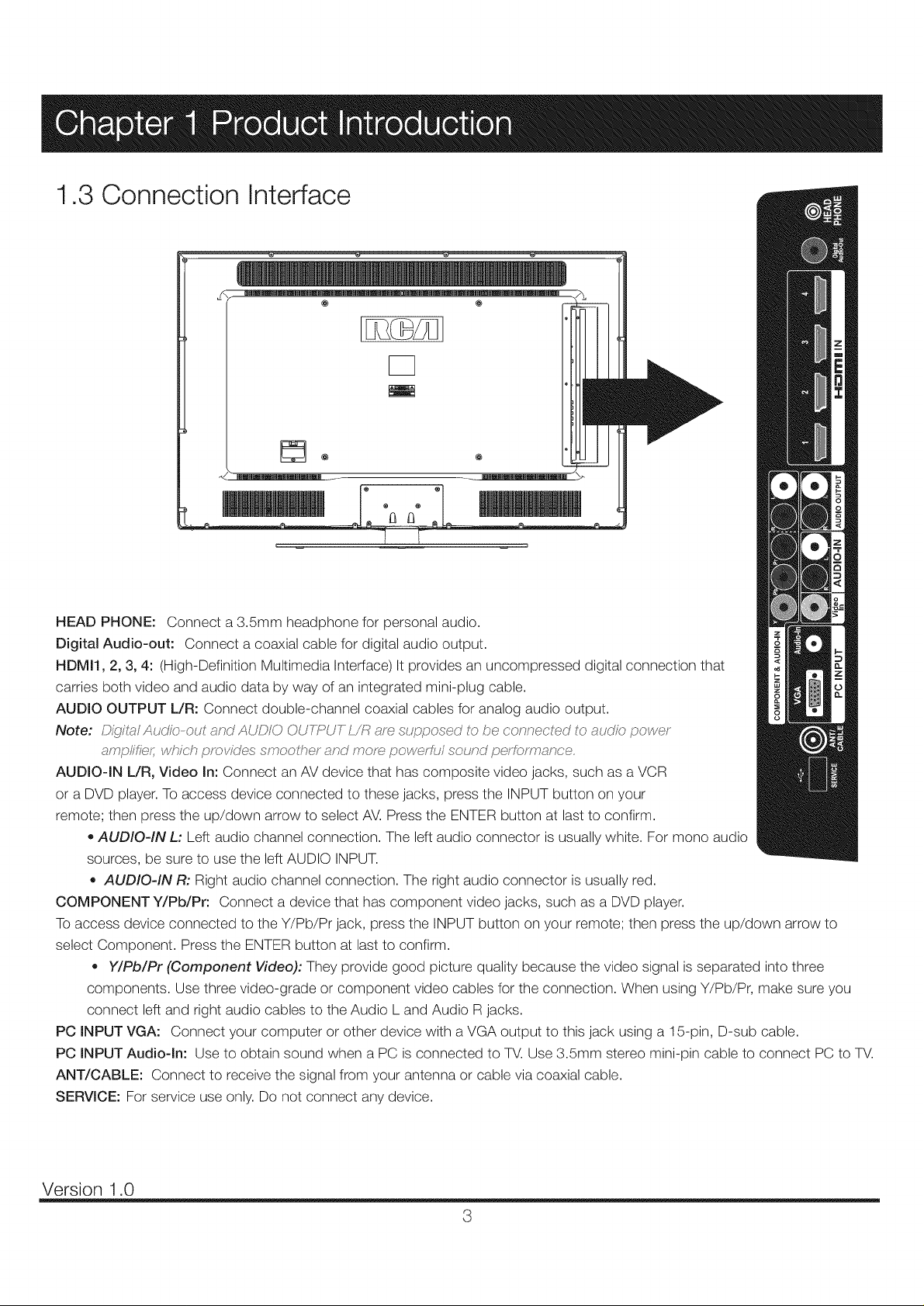
1.3 Connection Interface
@ @
HEAD PHONE: Connect a 3.5mm headphone for personal audio.
Digital Audio-out: Connect a coaxial cable for digital audio output.
HDMI1, 2, 3, 4: (High-Definition Multimedia Interface) It provides an uncompressed digital connection that
carries both video and audio data by way of an integrated mini-plug cable.
AUDIO OUTPUT L/R: Connect double-channel coaxial cables for analog audio output.
Note: Di!(yt,_lAuo'/_;,-out _nd AUDIO OUYT:_UY ,_resupf._osed to be connected to <_udk:;,povvey
ampfific;_ which prot_'des smoolher _<r_ndmorn powerful sound perfc,rmance.
AUDIO-IN L/R, Video In: Connect an AV device that has composite video jacks, such as a VCR
or a DVD player. To access device connected to these jacks, press the INPUT button on your
remote; then press the up/down arrow to select AV. Press the ENTER button at last to confirm.
• AUDIO-IN L: Left audio channel connection. The left audio connector is usually white. For mono audio
sources, be sure to use the left AUDIO INPUT.
,, AUDIO-IN R: Right audio channel connection. The right audio connector is usually red.
COMPONENT Y/Pb/Pr: Connect a device that has component video jacks, such as a DVD player.
To access device connected to the Y/Pb/Pr jack, press the INPUT button on your remote; then press the up/down arrow to
select Component. Press the ENTER button at last to confirm.
,, Y/Pb/Pr (Component Video): They provide good picture quality because the video signal is separated into three
components. Use three video-grade or component video cables for the connection. When using Y/Pb/Pr, make sure you
connect left and right audio cables to the Audio L and Audio R jacks.
PC INPUT VGA: Connect your computer or other device with a VGA output to this jack using a 15-pin, D-sub cable.
PC INPUT Audio-In: Use to obtain sound when a PC is connected to TV. Use 3.5mm stereo mini-pin cable to connect PC to TV.
ANT/CABLE: Connect to receive the signal from your antenna or cable via coaxial cable.
SERVICE: For service use only. Do not connect any device.
Version 1.0
3
Page 6
2.1 General Information
GENERAL DESCRIPTION
OVERVIEW
V500HJI-L01 is a 50 TFT Liquid Crystal Display module with 12-CCFL Backlight unit and 2ch-LVDS interface.
This module supports 1920 x 1080 Full HDTV format and can display 16.7M colors (8-bit). The inverter module
for backlight isnt built-in.
FEATURES
- High brightness (350 nits)
-- High contrast ratio (4000:1)
-- High color saturation (NTSC 72%)
-- Fast response time (Gray to gray average 8 ms)
- Full HDTV (1920 x 1080 pixels) resolution, true HDTV format
-- DE (Data Enable) only mode
-- LVDS (Low Voltage Differential Signaling) interface
-- Optimized response time for 60 Hz frame rate
-- Ultra wide viewing angle : Super MVA technology
-- Rolls compliance
GENERAL SPECIFICATIONS
Item
Active Area
Bezel Opening Area
Driver Element
Pixel Number
Pixel Pitch(Sub Pixel)
Pixel Arrangement
Display Colors
Display Operation Mode
Surface Treatment
Note (1) Please refer to the attached drawings in chapter 9 for more information about the front and back outlines.
Note (2) Please refer sec 3.1 and 3.2 for more information of Power consumption
Note (3) The spec. of the surface treatment is temporarily for this phase. CMI reserves the rights to change this feature.
1095.84(H) x (V) 616.41 (50 diagonal)
1102.84(H) x 623.41(V)
a-si TFT active matrix
1920 x R.G.B. x 1080
0.1903(H) x 0.5708(V)
RGB vertical stripe
16.7M
Transmissive mode / Normally Black
Anti-Glare coating (Haze 3.5%),Hardness 3H
Specification
Unit
am
mm
pixel
am
color
Note
(1)
(3)
Version 1.0
4
Page 7
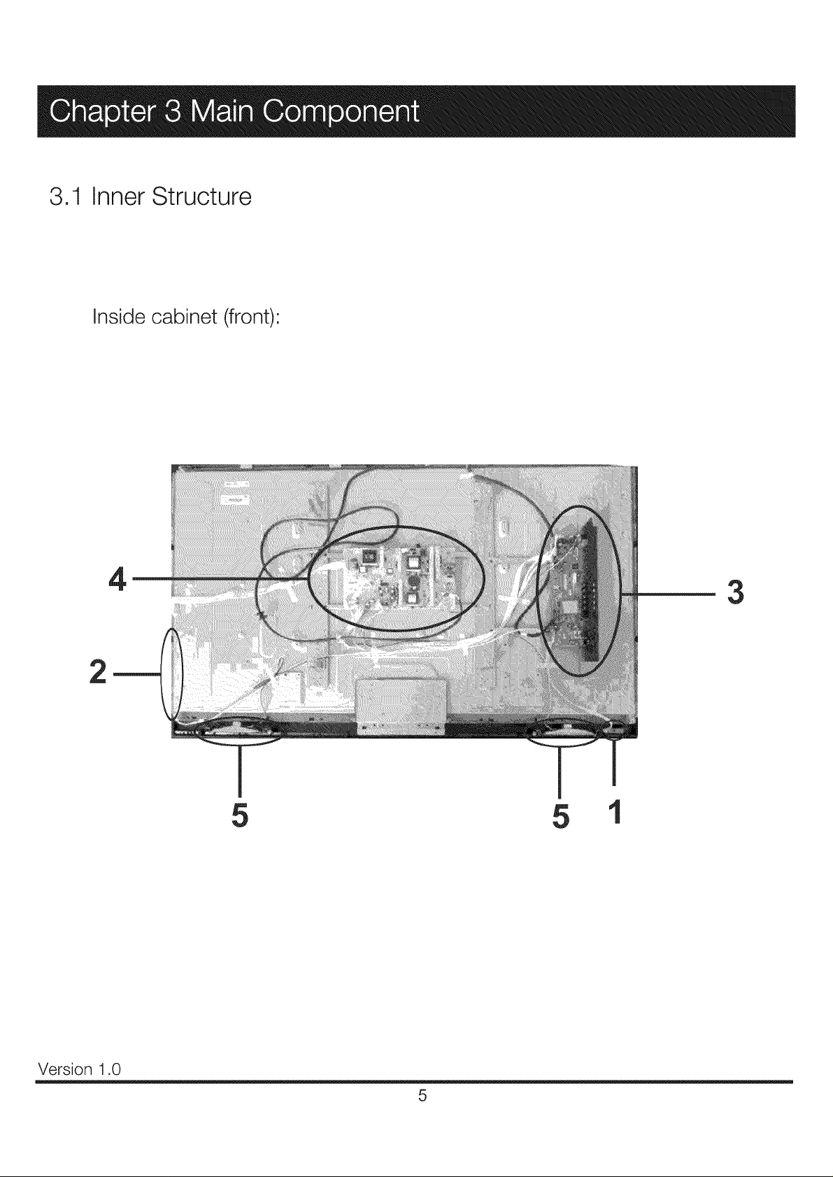
3.1 Inner Structure
Inside cabinet (front)
2
4
3
5 5
Version 1.0
5
Page 8
Item List
1 RE32185B050 IR board 22F, 38.5X12.3X1.6mm (1)
2 RE0340E011 Key board 22F, 107X12X1.6mm (2)
3 RE01 TC81ELNA0 Main board T.RSC8.1E
4 RE46DZ2009 Power board IPB539 200W
5 RE261530458105 Speakers 8Ohm, 10W
Note: (1,2) 22F and dimensions refer to the PCB board.
(It is for version 2012)
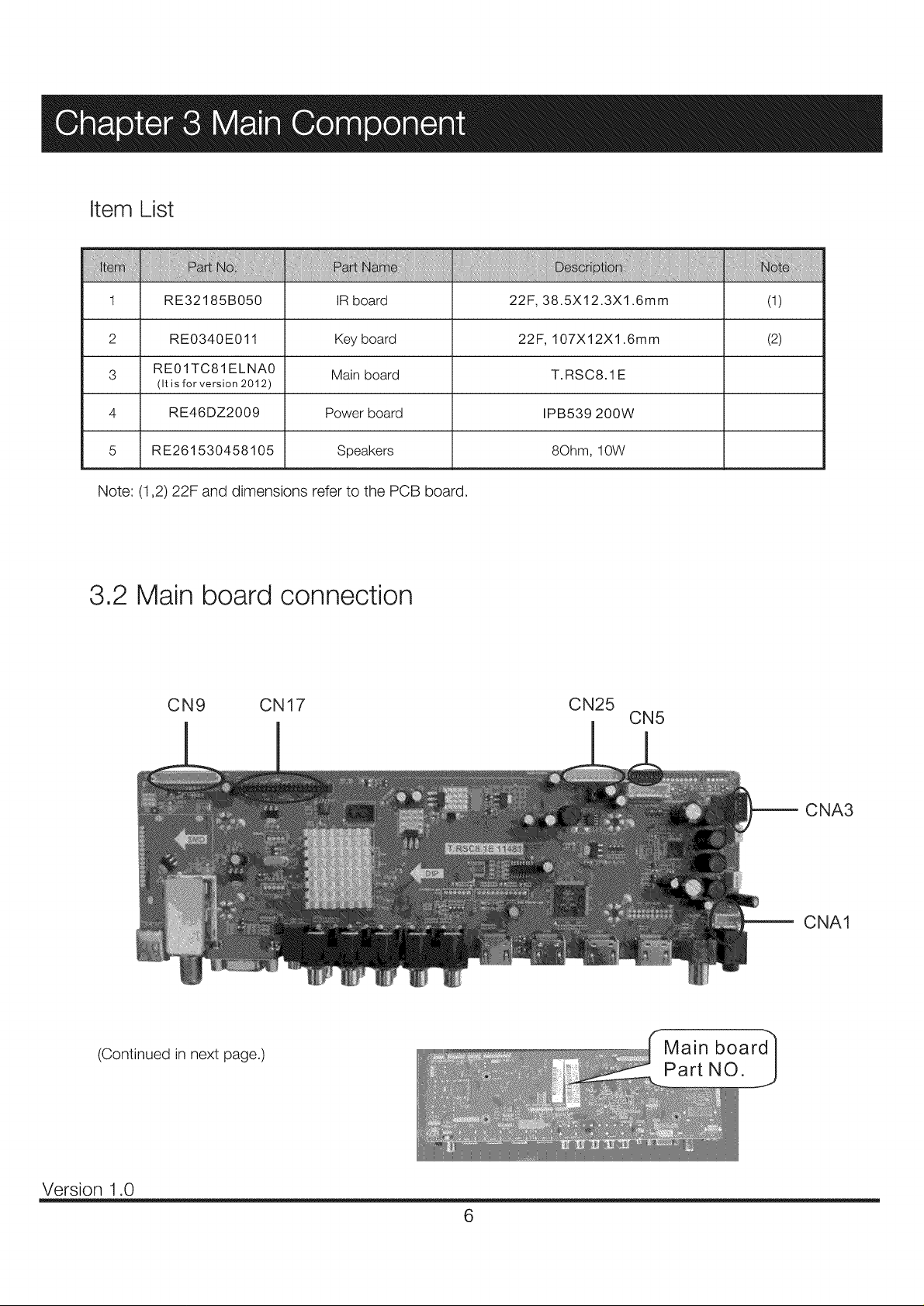
3.2 Main board connection
CN9 CN17 CN25
CN5
CNA3
(Continued in next page.)
Version 1.0
CNA1
Part NO.
6
Page 9
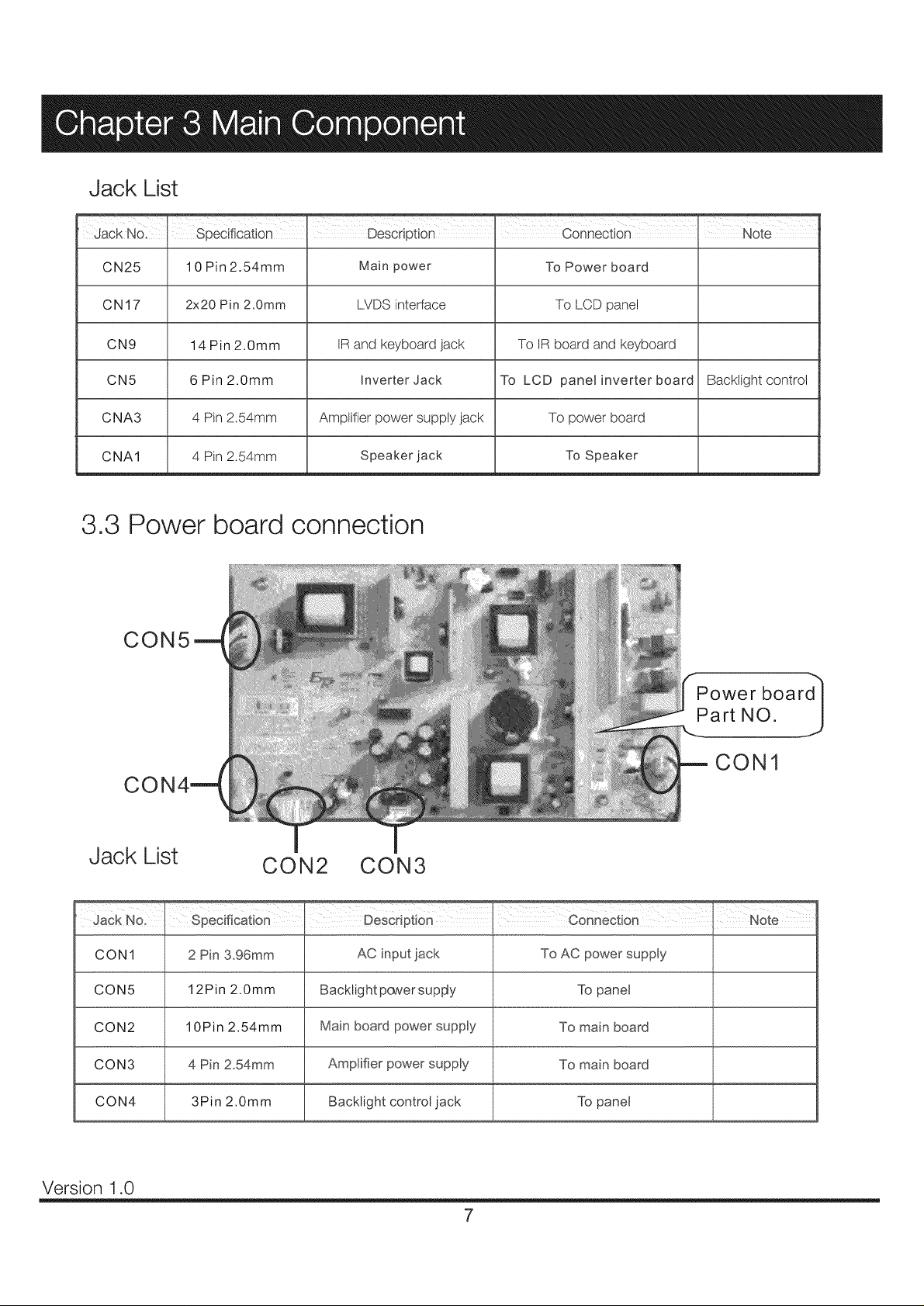
Jack List
Jack N01 1 Specification Description connection Note
CN25 10 Pin 2.54mm Main power To Power board
CN17 2x20 Pin 2,0ram LVDS interface To LCD panel
CN9 14 Pin 2.0mm IR and keyboard jack To IR board and keyboard
CN5 6Pin2.0mm Inverter Jack To LCD panel inverter board Backiightcontrol
C NA3 4 Pin 2.54mm Amplifier power supply jack To power board
CNA1 4 Pin 2.54mm Speaker jack To Speaker
3.3 Power board connection
CON5
CO
Jack List
Jack No.
CON1
CON5
CON2
CON3
CON1
CON2 CON3
specification, DeScdPt!0n connecti0n, NOte
2 Pin 3.96mm AC input lack To AC power supply
12Pin 2.0mm Backlight pcwersupFty To panel
10Pin 2.54mm Main board power supply To main board
4 Pin 2.54mm To main board
CON4 3Pin 2.0mm Backlight control jack To panel
Version 1.0
7
Page 10
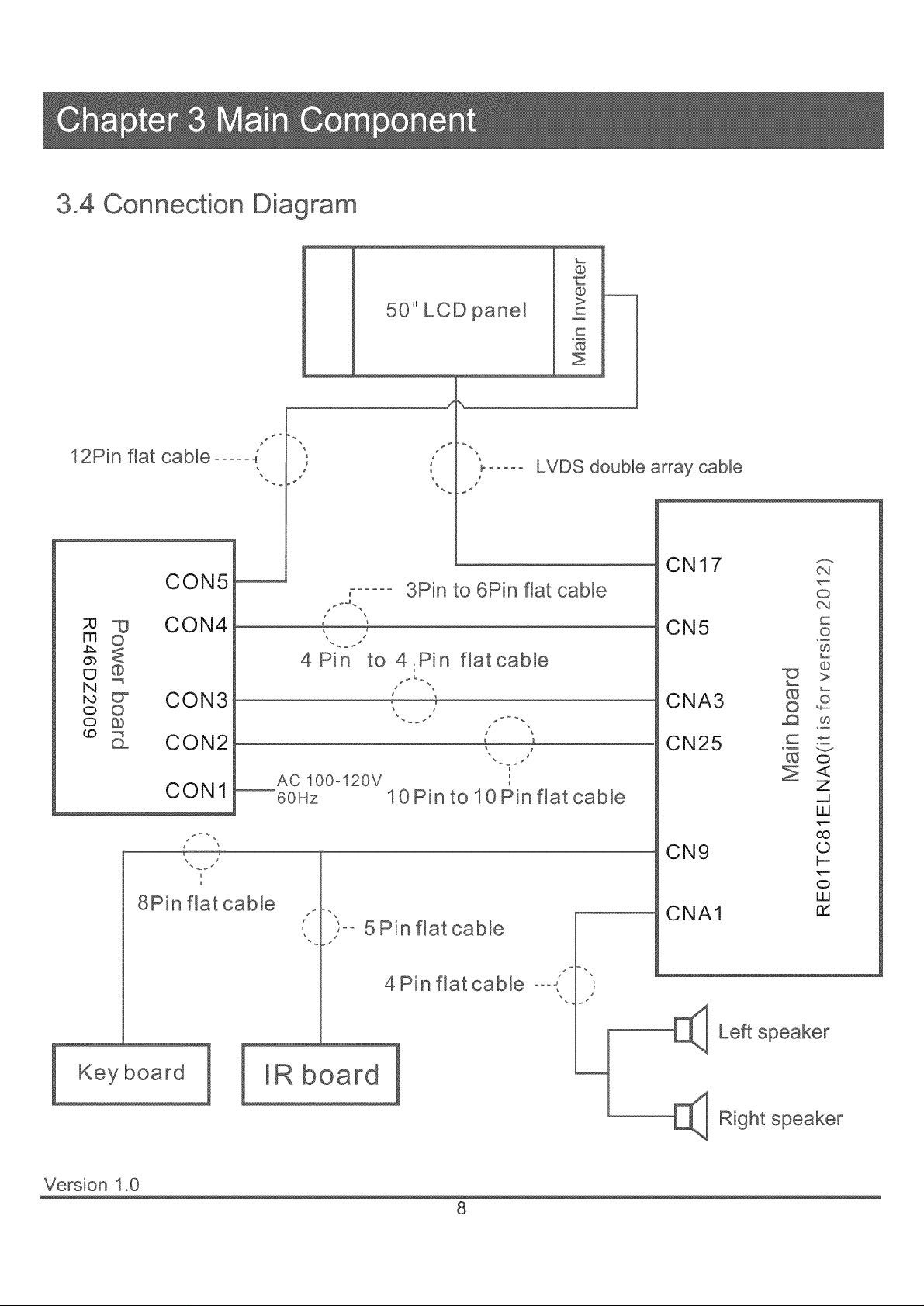
3,4 Connection Diagram
@
12Pin flat cable ..... 4
CON5
;u _ CON4
_o
8o
_ _ CON3 _
© O
_ CON2
CON1
8Pin flat cable
50" LCD panel
J
J \
7
4Pin to 4.Pin
AC 100o120V
60Hz
10Pin to 10Pin flat cable
5 Pin flatcable
LVDS double array cable
3Pin to 6Pin flat cable
flat cable
J _
'i
C
c
Z
CN17
CN5
CNA3
oa
o
oq
©
O9
@
©
O9
CN25
o
Z
uJ
oo
CN9
CNA1
©
b-
o
uJ
rY
Keyboard
Version 1.0
4 Pin flat cable °°°,
E]_ Left speaker
IR board
[_ R_ght
8
Page 11

Note: Before opening the cabinet and working on the repairs, please read the troubleshooting and Q&A attached in the
user's manual, which has covered most of the problems caused by unproper using or settings to the TV set. If that does not
work, please carry out the easy troubleshooting before checking or replacing the main parts of the television. The
troubleshooting guides given below base on the situation in which the TV's functions are set and used properly.
Plus, if the easy troubleshooting can not help, please work on the repairing according to the procedures given in chapter 5,
Exception Handles.
4.1 Troubleshooting for Common Use
TV can not be turned on
• Check the connection and condition of wires and inlets that relate to power board, including the AC power inlet, the
power incoming wire, wires between power board and mainboard, etc.
o Check the diagram arround power board to see Ifthere exists a short circuit or creepage.
• The power board may be bad. Please change the board for testing. If it cannot help, refer to the chapter 5 for more
intensive information.
• In addition, the malfunction of LCD panel can cause failure of power on. Please refer to 4.2 Troubleshooting for Displaying
for more information.
Auto turning off
o Check the sleep timer setting.
• Check the surrounding diagram of power board. The problem is most possibly caused by short circuit or wire breakage,
because this kind of malfunctions can cause excessive current, which will make the power board startup self-protection.
The screen goes black after a shorting blink
e If the TV screen can not display after the blink, that means the panel or other parts of equipment is broken (most likely by
unproper input voltage). Ensure the input voltage of every component, and then check the part that is suspected damaged.
o If this problem occurs repeatedly, check the surrounding diagram and connections of panel inverter board. Also, the
blacklight unit and LCD lamps should be checked out.
There exists afterimages after power off
• If the panel can work normally at the other time, it may be caused by bad mainboard. Upgrade to the latest software first,
if that does not work, attempt to change the mainboard.
There exists squeak when TV is working
e IListen to the squeak carefully to make sure where the noise comes from. If it is from speakers, the voice may be caused by
bad speakers. Change them for a try..
• If the noise comes from the inner parts of cabinet, it may be produced by abnormal AC current in power board. Change the
board and check its surrounding circuits for a try.
• Check the routing of wires inside the cabinet to suppress interference.
Version 1.0
9
Page 12
4.2 Troubleshooting for Displaying
Note: Ifthe troubleshooting given below can not help you, change the LCD panel for a try. But we strongly suggest you
regard changing the panel as the last step of fixing the display problem.
No display (including white screen, black screen, etc.)
• Check the power board output and main board input ports to make sure whether the TV has been turned on successfully,
because the failure in power on can lead to a no-display problem.
o If it is proved to have been electrified and turn on, check the LVDS cable first.
• Check if both of the two plugs of the flat cable between mainboard and power board have been well inserted into the slots.
Unstable power supply can also cause serious display problem.
• If the display problem only happens in one input mode, that may be caused by wrong version software. Update the new
software. If that can't help, change the main board for a try.
Screen tearing, or there exists moire on screen
• Bad LVDS cable and inappropriate panel driving voltage is still the biggest factor of this problem. So check them first.
e If the cable and voltage are correct, update the software for a try.
o Sometimes the fastening pieces can make unproper pressure to LCD panel, check them out.
• If the screen tearing happens in one or several input sources while the other source can display normally, it can be caused
by bad mainboard most likely. Please change the mainboard for a try.
• Refer to chapter 5 for more details and resolution ways.
Straight darWlight line(s) on screen
• If the bad line is very narrow, it is usually caused by LCD panel malfunction, change the panel for a try.
• If the lines link together and become a bad band, upgrade the software and then check the ports abd circuits of broken-
down output mode(s).
e If the darWlight line ,or band, apprears in all the input modes, please change the LCD panel. But we suggest you check the
panel inlet board(which links the panel and mainboard though LVDS cable) first, because sometimes the liquid crystal
displaying unit is okay, while the inlet board has a transmitting problem, which also will lead to a displaying failure.
• Refer to chapter 5 for more details and resolution ways.
Color cast or interference
• If the cast or interference happens in only one input mode, check the output port(on mainboard) and transmitting network
(arround mainboard) of that mode.
• If the cast or interference happens in all the input modes, please exclude the malfunction according to easy troubleshooting
for No Display. If that can not help, refer to chapter 5 for more details and resolution ways. In addtion, most of this kind of
problems come from the bad mainboards.
Version 1.0
10
Page 13
4.3 Troubleshooting for Audio
Note: Comparing with the display problem, the audio malfunctions are easier to work out. Constantly, if you have excluded
the possibility of bad speakers and bad connection of audio output, the problem generally comes from the audio processing
parts of mainboard. Please change mainboard for a try, or refer to chapter 5 for further information about repairing.
No Sound
o Check whether the speakers are broken first.
o Check the wire that links the mainboard and speakers. Watch if there is fracture or cladding material breakage.
• Check the joint of speakers and audio wire, watch if there is poor soldering or fake solder. Besides, the polarity mistake
can also lead to audio problem.
Volume too low
o Check whether there is a jam at the sound hole in front cabinet.
• Check whether one or more speakers are bad.
Sound channel loss or confounding
• Check whether the audio wires are installed reversedly. The left channel wire should be white and the right channel wire
is red.
• Check the audio output socket of mainboard to see whether it is wrongly inserted. If not, the mainboard audio output module
may be bad, refer to chapter 5 for more details and resolution ways.
• If the connection is stable and right, the mainboard audio output module may be bad, refer to chapter 5 for more details
and resolution ways.
Noise
o Check ifthere is anything should not exist inthe speaker hollow space (such as screws).
• Check if the antihunting EVA is broken or missing.
• Check if the speakers are bad.
4.4 Troubleshooting for Keyboard
No key can work
e Check the wire between mainboard and keyborad, watch if there is fracture or cladding material breakage.
• Check the joint of mainboard and keyboard wire, watch if there is poor soldering ofrfake solder.
• Check the resistances that locate on the keyboard PCB. Watch ifthere is wrong or broken ones. Also, the poor soldering
of fake solder should be concerned and checked carefully.
o Check the other components of keyboard(such as capacitances and microswithes) are wrong or bad.
Version 1.0
11
Page 14
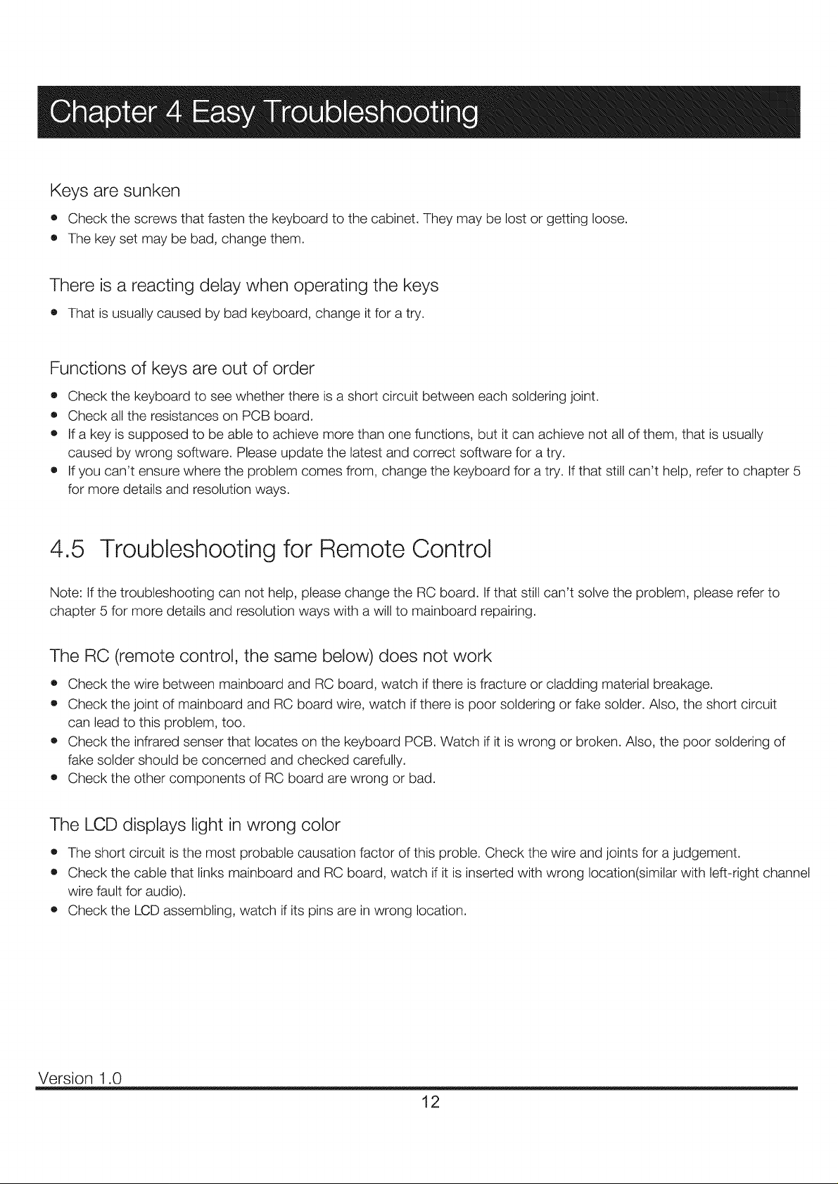
Keys are sunken
• Check the screws that fasten the keyboard to the cabinet. They may be lost or getting loose.
• The key set may be bad, change them.
There is a reacting delay when operating the keys
o That is usually caused by bad keyboard, change it for a try.
Functions of keys are out of order
o Check the keyboard to see whether there is a short circuit between each soldering joint.
• Check all the resistances on PCB board.
o If a key is supposed to be able to achieve more than one functions, but it can achieve not all of them, that is usually
caused by wrong software. Please update the latest and correct software for a try.
• If you can't ensure where the problem comes from, change the keyboard for a try. If that still can't help, refer to chapter 5
for more details and resolution ways.
4.5 Troubleshooting for Remote Control
Note: If the troubleshooting can not help, please change the RC board. If that still can't solve the problem, please refer to
chapter 5 for more details and resolution ways with a will to mainboard repairing.
The RC (remote control, the same below) does not work
• Check the wire between mainboard and RC board, watch if there is fracture or cladding material breakage.
• Check the joint of mainboard and RC board wire, watch if there is poor soldering or fake solder. Also, the short circuit
can lead to this problem, too.
o Check the infrared senser that locates on the keyboard PCB. Watch if it is wrong or broken. Also, the poor soldering of
fake solder should be concerned and checked carefully.
• Check the other components of RC board are wrong or bad.
The LCD displays light in wrong color
• The short circuit is the most probable causation factor of this proble. Check the wire and joints for a judgement.
• Check the cable that links mainboard and RC board, watch if it is inserted with wrong location(similar with left-right channel
wire fault for audio).
o Check the LCD assembling, watch if its pins are in wrong location.
Version 1.0
12
Page 15
Note: The exception handles are prepared for qualified personal only.
5.1 Display Exceptions
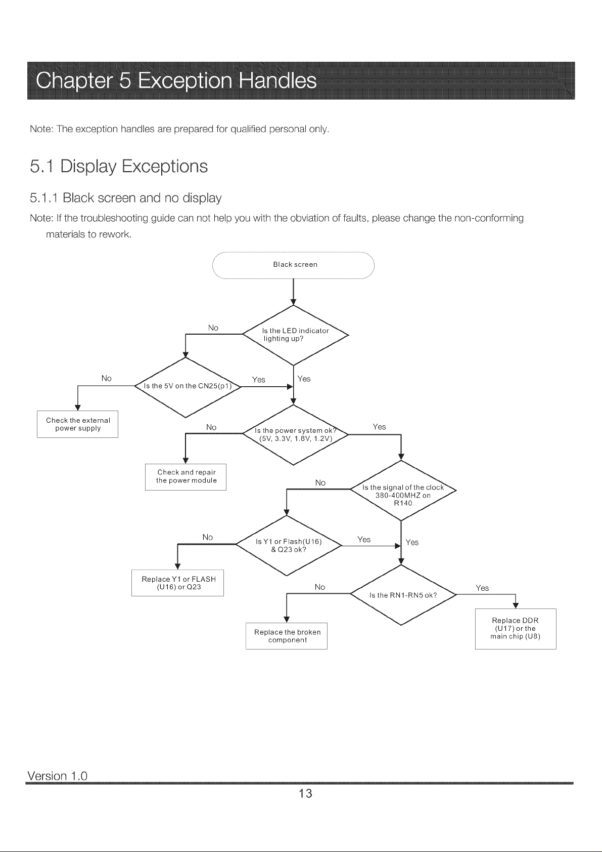
5,1.1 Black screen and no display
Note: Ifthe troubleshooting guide can not help you with the obviation of faults, please change the non-conforming
materials to rework.
No
No _ Yes
Check the external
power supply
No _[s the power system _ Yes
Check and repair
the power module NO
N©
ReplaceY1 or FLASH
(U16) orQ23 NO
IsY1 or Flash(U16)
,L
Replace the broken
component
signal of
380-400MHZ on
R140
Yes Yes
Yes
Replace DDR
(U17)or the
main chip (U8)
Version 1.0
13
Page 16
5ol DispJay Exceptions
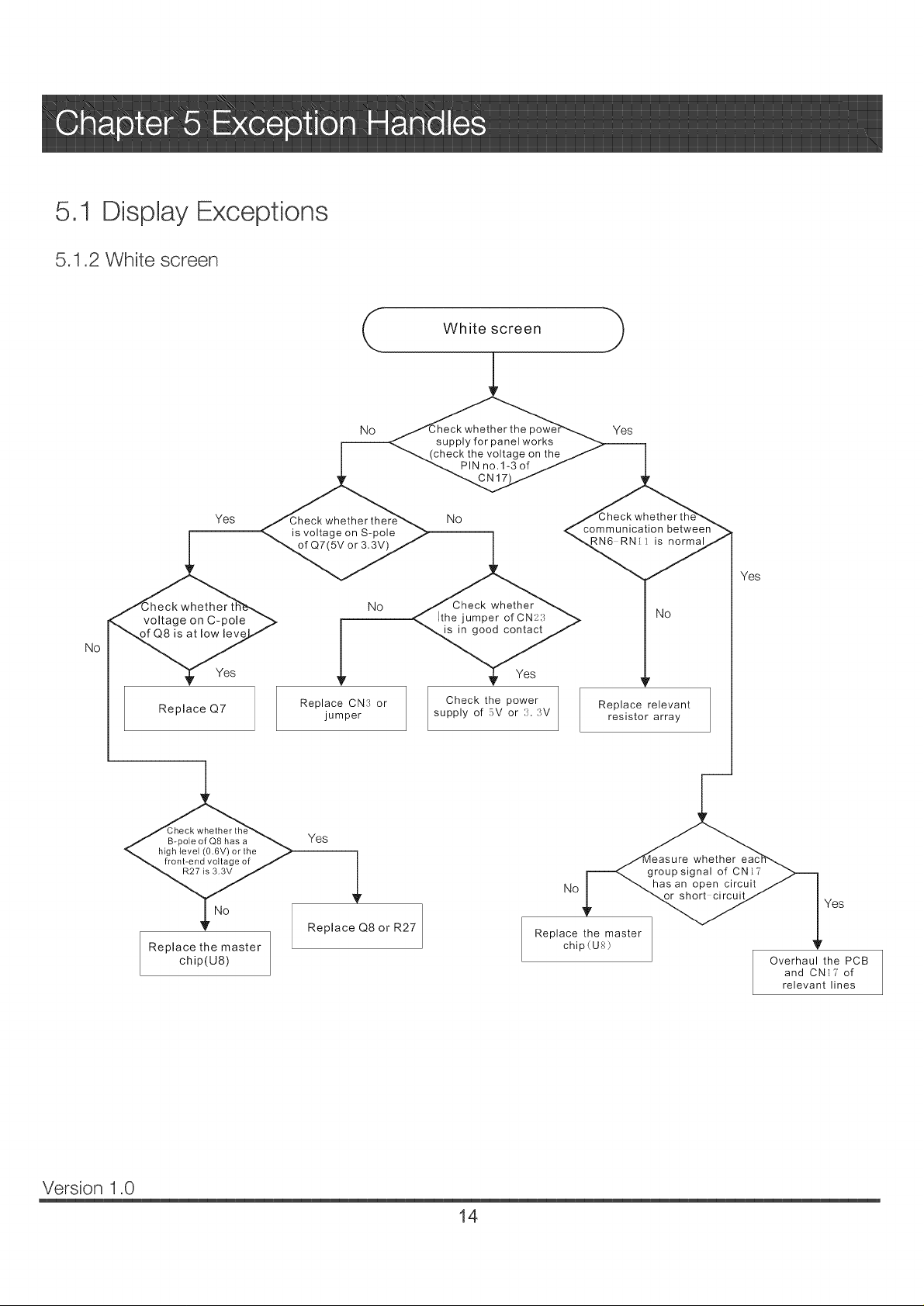
5.1.2 White screen
White screen
No
Yes
is voltage on S-pole
of Q7(5V or 3.3V)
No whether
voltage on C-pole
No
is at low lew
Yes
Replace Q7
heck
pole of Q8 has a _.
level (0.6V) or the ,_
nt-end voltage of J
Replace the master
chip(U8)
Replace CN:_ or Check the power
jumper supply of 5V or :X :W
Yes
Replace Q8 or R27
supply for panel works
check the voltage on the
PIN no.1-3 of
No
Ithe jumper of CN2?,
is in good contact
the
Yes
No has an open circuit
Replace the master
chip(Ug)
Yes
o m m u nica tion between
i_normal
NO
Replace relevant
resistor array
group signal of CNI?
short circuit
Yes
whether
Yes
Overhaul the PCB
and CN]? of
relevant lines
Version 1.0
14
Page 17

5.1 Display Exceptions
5.1.3 Dazzling screen
No
Reset the driving voltage
Check if the LVDS
cable is bad
Yes
e if the Yes ]
panel is bad? Change LCD panel
No
Check if the out
network and the
normal
Check the power supply and
clock circuit of U8
No
No
Change main board ]
___ Upgrade firmware or adjustLVDS MAP
Change LVDS cable
J
Version 1.0
15
Page 18

5,2 Audio Exceptions
5,2.1 No sound (completely)
No sound
Check if there
is audio input
Yes
<_, volume are
Yes
Does CNA1
_ve output signa
No
if the
p1,2,3,34,35,36 of
UA1 s ok?
Yes
Check ifp19of
UA1 have high
level voltage
Yes
No
Check external equipment
No
Set the mute and volume 1
Check the TV speakers 1
Audio power supply circuit 1
is bad, change main board
No
Check the MUTB/STB circuit,
if bad, change main board
1
1
Yes
Checkifthe p15,20
21,22 of UA1 have
signalinput?
No
Version 1.0
Yes if F Yes
of Ual have PWAsi
_utput
Circuit between U8and UA1
is bad, change main board
Change U8
No
change main board
Audio input circuit is bad,
Circuit between Ual and CAN1
is bad, change main board
16
,4
Change UA1
1
Page 19

5.2 Audio Exceptions
5.2.2 No sound (TV)
Yes
Check if the circuit
betweenUT3andU8 sOK
No
Change UT3 1
Yes
Refer to NO SOUND
Change U8, if that doesnt
work, change main board
1
Version 1.0
17
Page 20

5,2 Audio Exceptions
5.2.3 No sound (HDMI)
Is the signal No _]]_1
source HDMI OK?
Yes
1
Unsupported signal, change
input signal of HDMI device
1
<,_ Is the EDID(1) YeS>ill _
Note (I): EDtD means Extended Display Identification Data
Check if the PC/AV
sound is normal
Yes
Upgraded firmware
No
Refer to NO SOUND
Change U7or U8
or main board
Version 1,0
18
Page 21

5,3 Function Exceptions
5,3.1 TV function
rv can't scan channel/no picture}
_ m_
<_Check !!p14an_-- I2Cnetwork is bad,
No _d Check-Pv' RF signal
'_m (antenna,cable)
l by UT2, LT17
YesA
N___ UT3 s bad, change UT3
Note: (1) iF: Intermediate Frequency
(2)AGC: Automatic Gain Control
Change main board
Change U8
1
Version 1.0
19
Page 22

5.3 Function Exceptions
5.3.2 HDMI no picture
\\
No signal or image abnormal under HDMI )
J
\
Replace the signal
source
Overhaul the relevant
circuits between HDMI
input channel and U7
Replace U7
Overhual the circuit
between U8 and U7
No
signal source under
No
on the pin under relevant
HDMI channel of U7
No
output signal on the pin
under HDMI channel o
No wheth_
signal on the pin _>
_relevant HDMI channelJ
the in
HDMI is norma
Yes
if the input
are norma
Yes
J7 are norma
Yes
Version 1.0
Replace the master
chip(U8)
20
Page 23

5.3 Function Exceptions
5.3.3 YPbPr no signal
YPbPr no signal J
work, change main board
Check the YPbPr AV device |
]
or YPbPr cables
J
U8 surrounding circuits
are bad, change main board
U8 front circuits
are bad, change main board
Version 1.0
21
Page 24

REC8(it is for version 2012) series main board has a USB SERVICE port, which is reserved for service use only. Please
upgrade the firmware according to the instruction below.
6.1 Direct upgrading (do no need normal display)
STEP1
Get an empty USB disk with size not larger than 2GB, copy firmware file (CompBase.bin, or AIICompBase.bin) to the root
directry of disk.
Note: the size of USB disk can not be larger than 2GB, and before copying the firmware file, make sure the disk is empty.
And the file must be placed in the root directry.
STEP 2
Turn off the TV, insert the USB disk into the SERVICE jack on the side panel of TV and then turn on the TV. After turned on,
the TV's LED indicator will shine red and blue alternately. Wait for about one and half a minute to accomplish the upgrading.
Note: DO NOT power off or unplug the TV while upgrading.
6.2 Factory upgrading (need normal display)
STEP1
Get an empty USB disk with size not larger than 2GB, copy firmware file (AIICompBase.bin only) to the root directry of disk.
Note: the size of USB disk can not be larger than 2GB, and before copying the firmware file, make sure the disk is empty.
And the file must be placed in the root directry.
STEP 2
Turn on the TV, insert the USB disk into the SERVICE jack on the side panel of TV. Then press the remote control buttons
"MENU"--_ "1147" to enter factory menu (see below).
STEP 3
Choose "USB UPDATE" and press OK. Ifthere are "CompBase.bin"
and "AlICompBase.bin" in the disk at the same time, be sure to select
"AIICompBase.bin" to update. The upgrading phenomenon is the same
to direct upgrading.
Note: DO NOT power off or unplug the TV while upgrading, otherwise
the upgrading will fail, and the main board will be unable to upgrade
normally any more.
Version 1.0
22
Page 25

6.3 Upgrade Color Balance Table and Backlight configuration file
1.When you finish to upgrade the basic software, it will display the software date in the factory main menu.
the software date
2. Download the color balance table file (CompQuality.bin) and backlight configuration files (ComScaling.bin) to the USB
disk. The way of upgrading the color balance table is the same as upgrading the basic software, refer to 6.1/6.2.
NOTE:
o The order of upgrading TV software: Firstly, basic main board software; Secondly, backlight configuration files and
color table.
o Make sure that there are two files in the USB disk (ComScaling.bin and CompQuality.bin), insert the USB disk
to the TV, and then press POWER button to turn on theTV, it will spend lOsto finish upgrading the software.
o When finish to upgrade the backlight configuration file, the TV will upgrade the color table automatically.
o Pull out the USB disk after finishing upgrading software.
o DO NOT power off or unplug theTV while upgrading, otherwise the upgrading will fail, and the main board will be
unable to upgrade normally any more.
3. After finish to upgrade the software, the software date will change:
Color Table
In "VERSION INFO", it displays the panel model and Backlight Adjust.
Version 1.0
23
Page 26

Adjust Color Balance Table (White Balance)
FACTORY MAIN MENU has a WB function, you can adjust the white balance in this menu by adjusting R/G/B value. Press
the remote control buttons "MENU"_"1147" to enter the factory menu (see below).
Choose "WB"(White Balance) and press OKto enter the submenu.
Press left/right button to select the color temperature mode: Warm, Normal, Cool.
Press Up/Down button to select the R Drive/G Drive/B Drive/R Cutoff/G Cutoff/B Cutoff.
Note:
1. The RGB Drive affects the white field mainly: the RGB Cutoff affects the black field mainly.
2. In WB menu, you can adjust the color temperature, but the data cannot be updated to the TV system automatically,
you can write down the date that you want and contact the factory to update the software.
3. Color balance table upgrade is not available for models produced before 2012.
Version 1.0
24
Page 27

I 2 3 ¢ 5 d 7 8 _ I0 11 12
i
Main Board (SCH)
RE01TC81ELNA0 (2012)
NB3V D8
I
I
IT 2
10Kohm-@D2-_5%- M 6W
10Kohm-@D2-_5%- H 6W
PMBT390_
POWER ON
UI
_ZI 117H-ADJ(TR)EI
< VO_ ---_J
CN25
IOPlN 2 5&I>H G
_%_STB
R215
100ttF-25V-+20%-6*7-105
0 htF-0402-Y%_-+ 80%-20% -16_,
0 htF-0402-Y%_-+ 80%-2_ 1,-16_,
/17
510oban-_02-+-_%- 1/I6W
PMI3T39BI
GND
VDDI2 O) L
O
GND
_%_STB
2' 2
OND
0 htF-0402-Y%_-+8@ b-2(P,b-16_, GND
U3
AZ 1117H-3 3(TR)EI
1
] _ I
l0ttF-0805-Y5_,C+80%-20%- 10\'
33V STt3
TT
0.1uF4?g02-YSV480%-20%-16V
4K7dun-0402-_S°>l,'l_V
AO34(_
100uF-25V-_20%-6*7 105
0 htF-IMO2-Y5_,c+ 80%- 20%- 16_,
PMI3T39BI
PVLU
_R2'46
Q8
--___----
G%_D
t VC?Panel
GND
CN3
3 PI2V
3PIN-25&D-H-M
i
IN5819-5 \_
NO 10ttF-)805-Y5V-+80%- 20%- 10V
htF-Wo03 Y5V-+80%-20%- 10V
I
p3o,
VDDI2 _Q6 PMI3T39044KT°tIln-('_)2-_-_%-II6W
10Kohm-( '_)2-_5%- 1,16¥V
GND
0 0 htF4MO2-X7R-±I 0%-50\,
(21
OND
htF-0603 -Y5_,c+ 8(P, b-20%- 10V
l0ttF-0805-X5R-±I 0%- 63V
AZI 117H-,ad)J(TR)E 1
120otm_-0402-=t %- 1/16_V
56ohm-0402-=5%- 1/16¥V
L2
100ttF-16_,_20%-6*7-105
U4
_Z 1117H-ADJ(TR)E 1 A\'DD 12
I _vo_--_
G]N'D 100ttF-16_,c±2(P,b-6"7-105
U6
C6113 VO 2 ,
< VO
N_3\
4
/
,?
2
T
_RI6
GND
7 100uF-16V-_20%- 6"7- 105
G%'D
VDDI8
P5V
i
T
G%_D
0 htF-lMO2-Y5_,cq
C1
D
0%-20%- 16_, G]XD
h_0603-YS_,_
lc_ E
: 1 TCI3
htF-Wo03-Y5V-+ 80%-20%- 10V
U2
_ZI 117H-3 3(TR)Et
E 4
<vo_-_ 2H
1 T
_8_ 1,-20%-10\, G%'D
UI3
_ZI 117H-3 3(TR)Et
<vo_--_J_
G]XD 10ttF-0805-X5R-±I 0%- 63V
I00ttF- 16_,_+2(P,b-6"7-105
4K7dun-('_}2-_S°>i,'l_V
BL ON R34
10Kotm_-0402-+__q>li16_V
PMI3T39{M
PMI3T39_
510ohm-_02-_5%- 1/16W
1Kolm_-0402-+_5%-U1o%V
BALKLIGHT _)J
10Koban-0402-_5%- H6W
PMBT3904
htF-0603-Y5_,c+ 80%-20%- 10\,
P5\
R31
R29 IKol?an-0402-_5%- Iit6W
R32
33d_m-0402-_5%- I,'l 6_V
CN5
_1_
GND
Pd5
R36
K;7
300oban-0402-+25%
GND 300oban-0402-+25%
33VD
G%'D
470ttF-16_,c+2(P,b-8 I_ 105
0 0 htF-0402-X7R-±I 0%- 50V
5K6ohm-0d02-_5%- 1,'I6W
I 2 3 ¢ 5 (5 7 8 9 I0 11 12
7 5
GND
, T
(HS010U-220K-045-G
I0IC%lm>('_)2-±1%- 1/t6W
3K%ban-0402-±t%- H6W
RI 2 G]XD
GND
470t_16V-+20%-81- 105
*9
--_----
G%_D
G%_D
Page 28

.......... _ .. .J ..................
? 3 ! ,_ . .. o .... ,. .............
Main Board (SCH)
RE01TC81ELNA0 (2012)
DDC S(E T_
DID(" SDA Rg_;
p.&NEL ON DQ,:
KEY IN(} *ad5-_-
LINEOLT NL'TE B13:,
KEY INI
U8G
: GPY08
GPY1C
GPY!I
GPY12
MADIN1
MADIN3 : SFWP N
MADIN4
CN9
, _SV T
2 LE) R
3 LB3G
4 IR
5 GND
6 _ RII4
8 _ RII9
7 K1 RtI8
9 K3 RI20
I0 K.4 R122
II 1_ R124
12 KI3 RI07 ^'^ ^ _"_
13 1(7 R126
14 GND 75ohm-O40Z-:k_/_ 1q6W
14PIN-2 0-D-H-G
_.Lc119
G%'D 100ol}m-0402-+5%- H6W
52- STB
%/X/" :
3IC;ohm- (/v!LP_-+5%-1/1o%V
1Kohul-0402-+S£ 1,-1/16W
6K8ohm- (/vRP_-+5%-1/1o%V
tKohm-0402-+5%- Ii16W
3IC;ot]m- (g02-+5%- 1/1o%V
75olnn-0d02-_Sq 1,-Ii16TV
75olnn-0d02-_Sq 1,-Ii16TV
33\ STB
33pF-0402-NPO-i5%-50V
PMLIAI48L
4K7ot_n-0d02-_5%- H6W
3IC;dm>{M02-+5%- H o%V
3K3dnn-{g02-+5%- [ 16W
I(T%05 I8030FR
I(T%05 I8030FR
¢_'D
IR IN
L9
LI0 ¢.-../.-..1%
3(£bhm-0d02-_25%
300ohm-0d02-£.5%
3.3V STB
R8A66983B G#U0
F2 BL ON
D I A SEV[
BA(KLIGHT ADJ
DVD EN
LEDR
P,318
./X/X.
10Kotm>0102-+5%- 1 16W
510ohul-0d02-_5%- lq6W
PMBT39{_
300ohul-0d02-_25%
0 htF-0d02-YST-+80° 1,-20°1,-1o%-
R28
./X/X,
10Kotm>0_2-+5'V_ Ii16W
IKolnn-0_2-+5%- Ii16W
PMBT3904
0 htF-0_2-Y5V-+80_ {,-209_-1o%"
PSV
o
_Rt76
L5
m
m
GND
GND
S_ZSTB
'PSI9
GND GND
...... ........ - t 5 6 7 8
Page 29

............. J ..............
Main Board (SCH)
RE01TC81ELNA0 (2012)
RPll
4*33dm>0402-_5%- H6W
4 '5 o ,
U8H
<,G15 DVD STB
<.GI6 D DAT
'R238
A 3!
, 10Kobm-0402-_5%- H6W
, 10Kohln-Od02-_5_ _ H6W
I I / u16
RIC
I . I csa vo? 8
I
_vss Dn_ _
OND
W25Q32BVSSTG
BFTX
SFCS N
LII ' >
10Kol_n-0402-_5%- Ii16W
33dlu|-0402-_5%- 1,16W
uss o+ R109 ./%/N. R1%7
usB D- _ ,/N/N. Tt0
33\2 D GND
R252
4K7ol?an-0402-_5%- H 6TV
4KTd:an-0402-_5%- [,q6W
4RTohm-0402-_5%- 1/10%V
4RTd]m-0402-_5%- 1/10%V
PI0
5K6olml-0402-±l%- 1
SKSN
SbTK : NB2TDI FI
sFrx
IVB2TMS <'_
NL_2TCK :_-_
NB2TDO GI
AsmPx__x
XOUT25 "-'-_
_F_I6
£16
_.EI 5
_DI6
_DI5
_.17t15
_HI6
._j15
DVDIR
AS1,VO
AstEMD0
TRST N
TgK
TN,_
TDO
N{2'INblm>{MO2-+5%- H 6W
25MHz-+20PPM-20PF-HC- 49S
YI 33pF-O!O2-NF'O-+5%- 50\,
R250 33pl:-0402-2x'PO-+5%- 50\
L, T IH,,o-
R249
220o1]m-0_2-=5%- 1/1o%V
RESET N
C49
TCK ]l _-] NC!0 IuF-B402-Y52'_+8d_' 6-20%- 16_'
_5_ NC!0 IuF-O402-Y5%_+80%- 20%- 16_'
--'_'_'_ NC,0 hlF-0402-YSX -+B0_%-2_ B- [6&
_6_L_7 NC!0 IuF-0402-Y5%_+8d4;-20%- 16_,
(_'D
33V STB
M SDA
M_L
...... ........ - ' i ' 5 6 ' 7 ' 8
..... ......... ....... .......... ...... ....
R255 ./N/N. N(1A
Rm6
100olml-OgO2-+5_g Ut6TV L4,.:_
100olin>( J_P_-_5q¢ l '16W
SIDA[ FI,t_
RSA66983BG#U0
J14
/qf
"-_ 100ot_n-( '}4(P--_%q,' 16W
NC;100Kd,an-{g02-_5%- [ 16W G_'D
G2X'D SGMS09-S_LN3 0 IuF-O_2-Y5V-+8(P ;-20%- 16V
Page 30

I 2 3 4 5 6 8
Main Board (SCH)
RE01TC81ELNA0 (2012)
G%_D
, . 16c-0603-Y5V-+ 80%-2ff%- 10N _2
(N15
RUS_-U K-O4WH
AV1
C111 PSi,D110 _D3]
USB -%% _ FI ] o+Ii
-- UL(E0505 A015FR [ [
G%'D
L'L(E0505A015FR _x lb_'l S I _'_
CVBSI
G%'D
_ #+
Rg27 (_v_S 1
'N/N/'
YPbPri "f _N/Np R79 Y
YPbtM Pb' R82 Pb
YPbtM th" _/N_ R8__
'N/NP . Pr IN
NC'Lbhm-( '_}2-_5%- 1/16_V
NC'Lbhm-( '_}2-_5%- 1/16_V
NC'_ohm-( '_}2-_5%- 1/16_V
YRI
h_C-0_3 -Y5V-+ 80%-2de _ t0V
100Kotun-( '_P_-_5%- I,'I6W
100Kohm-( '_2-_5%- l,16_V
YR
YL
R94 NC' 100pF-('_}2-NPO-_5%- 50V
5X 4052
TRY8
>
YH II
IuF-0603-Y5V- +80%-20%- 10\,
_R43
GND
R73
YRI
RS,,, _, _ _Kotun-Od02-_5%- 1,'16W
..... II 39Kohm-O_02-_S£ _-1,16_•
YLI
.__99_Kot_n-( '_E- _Sq_-l,l 6%•
39Kotun-( '_}2-_5%- 1,16W
GND N(7 t0_)F-( '_E-NPO-_5%- 50\,
100Kolnn-0402-_5%- 1/16_vV
100Kolnn-0_2-_5%- 1/16_vV
5X 4052
t40
, Y LI'
_R72
--_=.--
G%'D
75°1nn-0_--_5%- H6_vV i
Y R @ LINE R
G%'D
1A\'.
__'-_- A\%8 + 13IX )
G%'D
OND
330pF-0402-X7R-±l 0%- 50V
_ 75dun-Od02-_5%- H 6W
22ohm-Od02-_5%- 1/16_V
---1
O]ND
AVI L IN
, AVI LIN
ms0
RI_ C1
71
R154 ] _ / 39Koln n-0402-+5%- M 6W
T _ T 22K°ln'a-0402-+5%- 1/16W
l 1 I 39Kolnn-0402-+5%- H6W
G_7)
AVl
22Koln n-0_2-_5%- 1/16_vV
NCq 00pF-0402-XTR-±l _ 6-50V
NCq 00pF-0402-X7R-±I @ ;,-50V
.................. T ............................
A\,3
YPbtM Y 3 CVBSI
_ @ YPbth[ Pb @
_._ YPbPr[ Ih 09
CJ_D
PI2\, A\<PI22
R74
LINE OLTfR
R91
AVI R IN
AVI L IN
R87'
Q1
G%R2&ID518030FR
ICS,ID518030FR
ICS,ID518030FR
ICS,ID518030FR
Cb4 R6 LINE R t292 < C89 R23 LINE L
CS_St
YPbthl Y
YPbth'l Pb
YPbPr 1 th
YPbth'[ Pb _lPb'
± I
]l'c_
tKoln n-gk!02-_5%- 1/16W 1Kolnn-0402-+5%- 1/16W
LINE OUTL
A\4 LIN C12411
htF-0_3-Y5X--+80%-20%- 10\,
100Kotml-0402-_5%-1,t 6W
100Koiml-0402-_5%- I,i_V
FB4
_PbPH Y
60olnn-0402-+25% /
75olnn-0402-_5%_ 1q6W _L
FB6 G_'D
60olnn-0402-_25% /
75olnn-0402-_5%_ l q6W _L
FB8 G_'D
YPbPH Pt
60olnn-0402-_25% /
75olnn-0402-_5_ t q6W _L
_%_4052
_R129
O_ND
t127
AV1LIN'
P_%__
0.16c- 0402-Y5V-+ 80%-2@ 6- 16%
t00olun-0402-_5%- I,'I6W
AV1 RI_ 1
Y RI' 2
AINR0 3 y lX
PC AI_ 4
D\]) t_ 5
A\, [ RtN C127 ] ]
htF-0(_3-YSX--+80%-20%- I0V
100Ko[m_-0d02-_5%-1 I0%V
100Koi_n-0d02-_5%-I,16W 'Pd30
6
V----7 sw 3x
2-%:::2....°
GND
R2'44
UI4
5X 4052
',128
OND
G%'D
16 5V 40_2
15 Y LI'
14 D\_) U
13 A{NL0
12 AVI LIN"
11 PC AL'
10 _%%V0
9 AS%V1
AVI RIN"
c144
-%_J_}52
TRI31
>
/
I
I
L PC AL'
---=.--
GND
GND G%'D
,] D21 _5i
GND G%'D
LII _ i BLUE+
PC
CNI4
_ PC ALI PC ALI RI7_w,,__ _ &_
CKTx3-35- i i -G R168
HS VC4k 99_Kotun-('_E-_5%- 1,16W
VSVC_
VGA DSDA ICS,ID518030FR
VGA DS(L
D7
33V STB( _--_ 2 D35 l-OiqF-001- -G
FI TCI23 R1'46_ R1,7( 4KTolnn-(gO2-+-_%-M6W L21
SArS<' / ? _.2 4K7olm>0402-+5%-H6W
G_9 SDA L_5 [ / DI_1SDA' / / I / • O-,i lo
I(_,%0518030FR 39Kolnn-0_;_5%- li16_vV
ICS,ID518030FR 39Kolnn-0_2-i5%- lq6W
ICvlD518030FR
__L
-_ l/ _ VGA DSDA 12 I;O;I 2
99_Kotun-('_E-_5%- 1,16W
t Hl3tcT //1/w
po,L _.1 .
htF-0603-Y5V-+ 80%-20%- 10\,
100Kolm>0402-_5%- 1/16W
100Kolnn-0402-_5%- 1/16W _'R132
___
__z_ / / i /
c,_D c,_ / / I /
33p_-_2-_o-.__-5ov / / I /
/
GND G%'D
>no,sm FO4 / / L--I _-l_-,/V_ ......
----1 t m05 t m06 /
4 _-_6./ ./ _ / ',_/
<; <; "; <;< / :'2K2°4n-O402-=5%-H6%
-%_J_}52
TR257
>
C14311 L
.... il " POAR'
htF-0603-Y5\_ +80%-20%- 10\,
100Kolnn-0402-_5%- 1/16_vV
100Kolnn-0402-_5%- 1/16_vV R258
I I
--_=.--
OND
KX_0518030FR
60otun-Od02-_25%
_L75ohm-( '_}2-_5% - 1/16_V
60otun-( '_}2-_25%
IC%_0518030FR
_L75otun-( '_}2-_5% - 1,16W
60otun-Od02-_25%
RI61 IC%'L0518030FR
_L75ohm-( '_}2-_5% - 1/16_V
*R159
R218'
220olm> 0402-_5%- 1,'t6W
47Kotun-( '_}2-_5%- I,'I6W
15Kohm-Od02-_5%- l,l 6_V
I 2 3 4 5 6 7 8
GND Pd60 C_'D
3IC_ohm-0402-i5%- t,'16_V Pd 79 3tC3ohm-0402-i5%- 1,'16_V
IuF-O603-SL%'- +Sift,;-2ff_,;- 10V PMBT3904
- 1
PMBT3904 hk<0603-'£%'-+ 80%-_ff_,;- I0V
1Kohm-0402- _5 _,;- 1,16_g• 47Kohm-( '_12-_5£ _- l,l 6_ •
47Kohm-0402-_5%- 1/16_V 47Kohn_-O_02-_5%- 1/16W 1Kohm-O_02-_5%- 1/16_V
_--'W"
G%'D
IqKolm_-0402-_5%- 1/ 16W
GND
DDC S(& DI _ sI ! i _3 _ NSYNC+
RI57 Pd75
100otun-0402-_5%- UI6W
DDC S(TL 100olnn-0_2-_5%- H 6_V
2K2olm>(H02-_5%- 1/16W
-.__--
Page 31
I ; 3 _ ...... i .... i .......... . . : ............................
Main Board (SCH)
RE01TC81ELNA0 (2012)
U8E
DAO LOUT
_7
IOKoban-0402-_5%- 1.16W
IOKoban-0402-_5%- H6W
AUDIO L
AUDIO R
CI21
22ohm-0d02-_5%- 1/16W
9 ..... _V_Nlg(} (24911
22ohm-£N02-_5%- 1/16W
BLUE+ _4_R191 ('2501[
22ohm-0d02-_5%- 1/16W
YIN /v_RI93 ]
PbIN /vv_Pd95 (25311
22ohm-£N02-_5%- li16W
PrIN /vv_RI96 (25411
22ohm-£N02-_5%- Ii16W
0.22tiF-0_2-XSR-±t 0%- 10V
t0Kot_n-0_)2-±l°i_ Iit6W
0 ItlF-(_O_-YSV-+80q 8-20°_-16%"
2 2uF- 0003-YSV-+80%-20%- 10V
(270
:x_ F--- A,'DD33,
:_Dll _/_-_ GND
,::xAIIa*BI01_(99+(96 lCB_
GN]D O]ND
ltlF-0603-'£gV-+80q ;-20°/_ 10V
0.IuF-B:!O2-Y%--+8@ _-2ff'_;- 16V
0.[uF-04_2-Y%'-+80° _-2(Pi_ 16V
__-- ZC104
A_NR_ II B_
&%'D
(2_
(206
Itk._-0603-Y5X:-+80%-20%- [ 0\ r
hkF,-0603-Y%_-+ 80%- 20%- 10V
VCOML
AINL3
AINR3 DA VCOM
i i _ ill i ii iiii: iii_
D'
VCFIvN AULK
R8A66983BG#U0
DA1 ROUT
C78
__L (_°
:Rs9
SPDIF Po7 /vvk, GND
R8A66983B G#U0
hlF-06_3-YSV-+B0%-2{B 8- [OV
RN6
LVOOU'_)P NI5 _ F_C/)+' 7 S
U8B
( RXOO+' i 2
• LVIOUT1M LI4 PrOOf Pv'<Et-' 7 _. 8
K15 REFR LV!CKOM MI4 RXOC- i
D RNH
'R289 RXO¢' 5 6
_5KOot_n-0d02-_t %-H 6W RXE4+' 3 4
R8A66983B G#U0
i GND ............ ........ ] ........
7
1 2 .......... ........... ........
LVOOIFf0M NI6 _ RXO0-' 5 6
P15 P,,'_t+ RXOI-' :1 2
LVI_WT1M __P16 PO_1- 4"22_@an-0402-_5%- l i6W
RI5 R,W_2+
LVOOUT2M RI6 R,N_- RXO2+' 7 _ 8
LVOOUT3P R14 Dye3- RXOC-' 3 4
LV1OUTOP LI5 RXO0+ 1
LV1OUTOM LI6 Pv_C0- 4.2Z2oban_£k!02__5%_l.16TV.
LV1OUT1P RN9
: LVIOUT3P 4"22oban-0402-_5%- I. 16_7
LV!OUT3M NI4 Dv_CI3-
TI4 _ RXO2-' 5 _ 6
T13 RXE4+
R13 _ 4"22°ba n-0402-_Sg/_ l ' 16TV
T16 _ RXO3+' 7 8
TI5 _+ RXD+' _ i
: LI3 DrOOl+
MI6 RXO2- _-' 3 4
MI5 RX02+ R)_t+' 5 _ 6
N13 RXO3+
PI4 Pv_Og RXEO+' 7 8
MI3 RXOC+ p04F_3_' "_ 4
PI3 F_O4+ RXE3+' _
% :! - . ........... • ..........
RXOI+' 3 4
RN7
RN8
RXO2# 5
RXED-' 3
RXE2+' 1 2
RNI0
RXEC-' 5 6
4.22oba n-0402-_5%- I. 16_V
RXO4+' 7 8
RXE42 i 2
4.22oba n-('_2-_5%- l. 16_vV
2
RXO0+
RXO0-
RXOI+
RXOI-
P.XO2+
P.XO2-
RXC)C-
P.XOG+
P.XCCr_
RXO3-
RXE)-
POE0+
RNEt-
RNEI+
PO<E2-
P,__+
_4_-(_+
RXEC-
RXE3-
RXE3+
RXQ4+
RXQ4-
IT'E4+
[ RXCG-' 17 18 P,XC_+' [
______('6_R_r_' _9 20 Pv'_+' ----F-(_9
/ F_I-' 21 22 P,,'_I+' [
/ R_-2-' 23 24 _+'
GX'D _ 7 28 R,'_C+' GND
J_,_ RXE3-' 29 30 R,.N_3+' J_
...--r_(74 O'ND 31 [ 32 GND T C75
| _ 34 Di_l)bv |
_L I \SELl 135 [ 36 V_%L2
V [ RXO4-' I 37 : 38 RXO4+' V
c,_> / RXE*' /39 / _ P0_4+' GND
NC,5pF_(IIO2_X7R_±I0%_501 ] NC'5pF-0402-X7R-±I 0%- 50V
NC.5pF-_02-XTR-±Ie0 b 501 2"20PIN-20-D-H-NC 5pF-0402-XTR-±K_ ;- 50V
/ _t v, M33V
2K2ohm-0402-t5%- 1,'16TV R110 _ RI 11"
3IC_oban-0402-_5%- 1,16W
t Y,29ohnl-0402-t5%- 1,'16TV _ i
VCL'Panel _ 2 Vtg-Panel
P,XO2-' H _2 RXO2+'
G2ND 13 14 GND
P.XOG' ]5 16 R_OC+'
O2ND 25 26 GT'TD V
CA'417
4 GND
6 GND
9 io RNOI+'
4KToban-0_2-1S%- H6W
_ P,XC_+'
LINE OLTL
LI>,EOUqR
htF-0603-Y5_,c+ 80%-2@ b-I0\,
htF-0603-YST-+ 80%-20%- I0\,
10Koim>0402-_-f%- H6W
1
/1;>
kl>
pI_T3904
220ohul-0d02-_5%- 1/16W
0. h_0402-Y5T-+80"_ ;-20° _-10_;
GND
P-%_
300oban-0402-+25%
C81
Page 32

1 2 3 ¢ _ 5 6
Power-Block
NDDI2
Main Board (SCH)
RE01TC81ELNA0 (2012)
A\,_D[2
o
I 12_1an-_3-_5%
33VA
O
I
33VD
<)
33\ STB
[
I_0805-XSR-±t_
120olm>_3-_5%
L24
120o1_n-_3-_5%
L26
ST
_',O h_-_O2-Y_%:-+8_ >2@ _ 1_,
I_-0805-XSR-±t_ _6 3V _ 7
NC' I_0805-X5R-±t_ _6 3V ND
120otm1-0603-_25%
L_7 (..-W,V-..,/%
120olmi-0603-+25%
L?8
0olm>0603-+5%- t, 10W
L39
120ohm-0603-+25%
L1 1111 ]]
63V
hlF-( MO2-YSV-+80%- 20%- 10_"
hlF-( MO2-YSV-+80%- 20%- 10_"
htF-O402-Y5V-+ 80%-20%- 16V
_t£,-080_-X_R-=t 0%-6 3V
\2+80%-20%-16%
V-+80%-20%- 16_,
V-+8_ b-2_ b- 16_,
0 htF-OdO2-Y%_-+ 80%- 2@b-16%
.... TC, TC, TC,7OTC, ,----C173--[C14
v v
OND O%'D
AVDD12W_
AYPPI_YAIP_
ION-0805-X5R-±I_ _6 3V
YPDgI.K _ L
_L
C182
0 h_2-Y%<+8_2_ l_,
0 h_2-Y5V-+8_ _2_ _ 16%_
8YIDID}}A G%'D
0 htF- 0_2-Y%'- + 80%-20%- 16%
0 htF- 0_2-Y%< + 8(£,b-2(Bb-16%
V
OND
0 htF-0_2-Y5_,_+ 8(Bb-20%- 16V 0 hl_O402-YS_,L+ 8(P, b-20%- 16%"
10Kolmi-0_2-+5%- H 6TV 100olmi- 0_2-+5%- l ,'I o%V GND
_-__C176
0 tuF-O402-Y5_,c+ 8(B b-20%- 16V
1"_77i l
0 htF-(gO2-YS_,C+ 80%-20%- lo%"
X7
C_D
-- --C76
X7
G%'D
0 h22-YS_,C+8_ b-20%- I6V
0 h_-_02-Y%_-+8_ >2@ _ 1_,
C179 0 h_-_02-Y%_-+80° >2@ _ 1_ ,
OND
_L _L
TC 8-
0 htF-_O2-Y%,C+80%-20% -16%
0 htF-OdO2-Y%,C+80%-2@ b- 16%
A\DD33\
O
__li L2
-- --C188 TClB9 TcIg0 T
V
11
CI93
C_'D
-- --C195
8,$V£ ¢7V
CI98
OND
10uF-0805-Xq{-±t 0%- 6 3\,
vDuiz v,'x>
G6
T_D12 V_
H6
T_D12 V_
J7
Jll
"VI)D12 V,_S
Kll
TI)D12 V,_S
L8
L9
"VI)D12 VSS
IvD
TI)D12 V,_S
N9
P9
K7
VDD12 VSS
Jl3
AT_DI_LLA VSS
K6
AVDD12PII_ VSS
Nil I
A'v_DI_LLC VSS
E12
T_D12S_B V_S
x
x_ i i ii i }
MI0
A'vgD12USB
7 x F x
E8
AT_D12T£_X"
A'_Dm2'<aDC AVSS!2USB
A_D12_L_X"
GII
H5
J5
Nil
Nb
NF
M8
iN(}
VOCQ18
_L
CI86
}
1
i
CI97
EXT CS
_,1_)
TI
VO;Q18
El0
A'v_D33"£_ AVSS33HDM[
(2
A'v_D33HDMI AV_33HDM[
(3
A'v_D33HDMI
Ell
A_D33TgLL
I96
A'vgD33ADAC
E6
A\rDD33A,_C AV_33ADAC
Nll
G4
VOOQ33 [ VSS
P5
VCt_33 _'SS
J12
VCt3Q33
K13
VC_'Q33
L12
VC_Q33
G12
FI2
H14
T
AVSS!2VADC
AV_12VAL_
AV_!2VADC
AVNS33AA_?
_gDFUSE 1
\_DFUS_
F6
F7
G7
H7
HI0
HII
J0
J8
J9
J10
K8
K9
KI0
V_
FII
KS
L5
L6
L7
P2
T8
V_
H8
H9
HI3
L10
(}8
G9
GI0
FI0
E9
D2
DI2
D5
E7
F4
KI2
Lll
HI2
E3
E4
E5
D4
_7
OND
G%'D
, 1 2 3 5 6
4
Page 33

1 2 3 4 5 6 8
84pad
cus tom)
Main Board (SCH)
DDR2-SDRAM (DDR2-800) (2-1ayers
iGbit (64Mwords x 16bits)
RE01TC81ELNA0 (2012)
R141
100ohm4402@1%-1/16W
R143
100ohm4402@1%-1/16W
4*33otml-0402-_5%- Ii16W
DI_acM A4
DI_acM CT_,S
DI_acM AI 1
DR&M A0
DR&M AI0
DIL&M AI
DRAM BA1
DRAM A9
DRAM WE
DRAM BA0
DR_M B}d
DRAM AB
DR_M A5
DR&M AI2
DRAM (NE
DRAb{ ,%7
DR_M RA, S
DR_M A6
DILkM
,62 5 W 6 SDA2 Kly;
DILkM
ODT 7 @ 8 SDODT K2k_
DILkM
(LK @3otml-_-'r'L%-liI6W R2_.
DILkM
<LK NzN/N/. SDCLK N _:
\DD18
O_4D
RN1
l %/,,/, 2 aOA4
3 W 4 SOCAS
5 %A_ 6 SDAll
7 _ 8 SOAO Jt__
l "_V' 2 SDA10 JQ.
3%.,%/, 4 .... Ltd.:
5 _/_ () SDBAI K4ct
7 _7/, 8 .... L21_,_
1%A/' (NO2-_'_SW#t6W IA F
3 @ 4 SDSAQ N21__
5 @ 6 SDSA2 P]-s
7 _ 8 SDA3 TWO.
1 %/kF 0402-_'8;c,4iIdW MJ_
3 ^.._.._ 4 SPA12 ]_[_.
5 %./_ 6 SOCKE 13_
7 _ 8 SDA7 N1;,
1 _/X/ O402-_5_lst_vV J3F>
3 W 4 SOAS K%_
R138 10ohm4)402-=5%-1/16W
R139 10ohm43402-=5%-1/16W
-- -- C146
0.1uF-0402-Y5V-+80%-20
SDVREF0 _
C147
7
Sh>rt wiring
DDR2 i/f-Block
U8A
Hi,_ SDA4
H3[_ SIX'AS
.r2_
i
SI)A10
SDA1
SDBA0
sDP,aS SDD_
SDA6 SDDQ1
SPA2 SD_4:
SI)ODT SDDQ3
SDCLK SDDQ5
sDcIx N SDDQ6
!_v SDD¢5
SD_v_J_-0 SDDNfl
x3
1
SDVREF1
H4_
DD (L SDDQS0 N
?
}* R145
(_ 5 150°hm-0402"_1%-l/161_SA66983BGgU0
SDDQ4
SI)DQ7
SDD08
SDDCT)
SD_4m
SDDQ11
SDDQn
SDDQ!3
SDDQi4
SDDND
SODQS0
sD_s_
SDDQS!N
i-[_2 SDA8 R137 _ DR4M A8
_N4 SODO0
_ SODO_
<_T4 SDDQ2
<_P3 SDDO3
_qT2 SDDO4
<aR4 SDDQ5
<_T3 sooos
_P4 SDDQ7
<_PS SDDO8
_c_5 SDDO9
<_R7 SODOIO
<xP6 SDDO11
<_LRO SDDO12
<{P7 SDD©13
_ _l'qS SDDQ14
<%_ SDD©15
<_P,5 SDDM0
_P6 SDDMI
_P5 SODOS0
1R7 SDDQS1
_ SDDQS1 N
33ohm-0402-_5%-l/16W
TP6 TP7
SDDOS0 N
l ] SDDQSt
SD_q_S[N
SDDQS0
SDDQSI
SDDQS0 N
SDDQS1N
DRacM(LK
DIt_n\IRtS
DI%&MC&S
DIt&MWE
DI%&MODT
iii
SODO0 G8
SODO5 G2
SODOI H7
SODOa K3
SODO6 H!
SDDO7 ]_)
SDDQ2 F!
SDDO3 F9
SDDO8 Cg
SDDOll (]_
SDDO13 D7
SDDO14 D3
SODO9 DI
SDDO12 D9
SODOlO B1
SDDM0
SDDMI B3
-- VSS
--
-- V,_,Q NC
-- V,%Q
-- VSSQ NC --
-- v,_,Q NC-
-- V_DL NC --
U17
DQ_ m
DQ2 A2
DQ3 A3
DQ4 A4
DQ5 A_
KS A6
DQ7 A7
DQ8 A8
DQ9 A9
DQ10 A10
DQll All
DQ12 A12
DQ13 BA0
DQ14 BA1
I m
DQ15 BA2
LDQS
UDQS _D
/LDQS _DD
/lo_.) S VDD
LDZvl VDD
L_Zvi VDD
J8
CK _DDQ
K8
-- iON _DDQ
K2
eKE _DDQ
/RAS VDIY4
iCAS VDIY4
/}XN _DDQ
ODT _DDQ
VSS
V_
v_Q
VSSQ NC --
VDDQ
,_DQ
VDDQ
_7)DL
M8 DRacM ,%0
_0
NB DRacM AI
M7 DR_M A2
i'.2 DR_M AB
N8 DR_M ,%4
N3 DR_M A5
i',7 DR&b{ ,%6
P2 DIL_M ,%7
P8 DR_%{ A8
P3 DR&M A9
M2 DtL&M A10
P7 DR_I All
R2 DRAM A12
L2 DRAM BA0
L3 DRAM BAt
LI DRAM BA2
A1
El
J9
ND
Cl
r
E9
G1
G3
G7
G9
J1
.12 DRAM SDVREF0
A2
E2
RS
R7
R3
TOP VIEW
rramx pkg. llxl]@a
VDDI8
VDDt8
O
R142 S C145
100ohm4_402-±1% 0 1uF-0402-Y5V-+80%-20%-16V
R144 I C148
100ohm4_402-±1%_0 1uF-0402-Y5V-+80%-20%-16V
OND
,%
"< 7
G%'D
\1)DIS
O
NC/10uF-0805-X5R-±10%-6 3V G']ND 0 lu F-0402-Y5V-+80%-20%-16V
1 2 3 ¢ 5 6 8
0 lu F-0402-Y5V-+80%-20%-16V
0 lu F-0402-Y5V-+80%-20%-16V
0 lu F-0402-Y5V-+80%-20%-16V
0 lu F-0402-Y5V480%-20%-I 6V
0 1 u F-0402-Y 5V4 80%-20 %-16V
0 1 u F-0402-Y5V480%-20%-I 6V
0 1 u F-0402-Y5V480%-20%-I 6V
0 lu F-0402-Y5V480%-20%-I 6V
Page 34

1 2 3 ¢ 5 G
Main Board (SCH)
RE01TC81ELNA0 (2012)
A
TI
15
16
17 NC --
GND
IS GND
OND
ii : 7
DVT- IOBCq'41F0
PI2V UI2 TU _%_
_VI _ VO _+i0 I 1_'_°hm-('_2-_5%- H 6W
01 _ 0 0 htF- 0_2-X7R-±t 0%- 50\,
1
2
NC
NC --
3 @(50
4 TU _%_
5
6 Ii. G_.D
7 TU SD_
SDA
8 _- S(K'
9 I1' O_'D
10
11
12 IF ACRP
13 IFN
Dlrl
14 11_
DW2
C1 l_otun-( '_2-_5%- H6W
G%'D
hlF-0603-".L%'- +80%-2(P. 6-
220ohm-Od02-_5%- 1/16W
220ohm-Od02-_5%- H6W
4K7olm>0402-+__%- H 6W
4K7olml-O_2-+2 %-H6W
R60
R235 CI39
TU 5V
1 TU SDA
IF AC_7"
TU SCL
R2_'/N/N" 1 F;gN "/N/N"
0ohm-0d02-_5%- 1/16W |
0 0 hff- 0402-Y5_,_+80%-20%- 16_,
2K2olml-O_2-+-_%- H 6W V
G%'D
U8F
TI2_
IFACK_
A16.___
IFAGC
i iiiiiiiiii
IF+
IF-
AI_>
BI2;_
]
l 2LT r__
O%'I) _ R236 {7203
0 hff'-O_2-Y%_- +8(£.6-20%- 1o%"
UTC78D05L
100uF- 16V-+20%-6 7-105
0 htF-0_2-Y%'- +80%-20%- 16V
*
1 2 3 ¢ 5 6 8
i i
iiiiiiiii
Page 35

1 2 B ¢ 5 6
Main Board (SCH)
RE01TC81ELNA0 (2012)
10Kohm-{}d02-__1%-Iit6W
330pF-_02-X7R-±I 0%-50V
htF-0603-YST-+80%-20%- 10V
NC'Lbhm-0402-=5%- 1/16_V
,%
q- ( LOUT
ROUT
1 2 3 ¢ 5 6 8
Page 36

I 2 3 4 5 6
Main Board (SCH)
RE01TC81ELNA0 (2012)
Diff. pairim_edancel00ohm
<ON3
21 SHWL2
23 SHELIA tlP DET
22 SHFAdB D2+
SHFAI1
471511051
_B
O'ND
<0N4
21 SHELL2
23 SHFJLL4 HP DET
22 D2 Slfield
SHFAdB D2+
SHFAI1
471511051
OND
Diff. pairim_edancel00ohm
CON1
21
23 SHFd_2
- SHELIA tlP DET
22 D2 Slfield
SHFAd3 D2+
SHFA_I
471511051
OIND
CON2
21 SHFdd2
23 SHELIA HP DET
22 D2 Shield
SHELL3 D2+
SHELL1
471511051
O_qD PS42Lad)DR0 _ I Title
DIX" DATA
DK'CLK
CE Remote
CK Stfidd
B0 Stfield
D1St_ld
D2-
D2 Slfield
GXD
DIX'DATA
DDCC_K
_-ERemote
_TKShield
D0 Stfield
D1St_ld
D2-
GND
DIX'DATA
DDCCLK
tZERemote
CK 5tfield
D0 St_ield
D1Nfield
D2-
DIX'DATA
DDCC_K
tTERemote
_K Shield
130 R_ld
D_ _ld
D2-
19 AHP{_
18 A1 _V
+5V
17 G2X'D
G2"D
16
15
14
Nc --
13
12
CK-
11 G2X'D
10 ARZQP
OK+
9 ARZQM
I30+
DI+
÷5V
OK+
I)0-
D0+
DI+
OK+
I)0-
120+
D1-
DI+
+5V
(K+
DL
DI+
I)0-
CK-
+5V
CK-
CK-
DO+
D>
NC--
D1-
NC --
NC --
I)0-
G%'D
6 ARZ1M
5 G%,'D
4 ARZ1P
3 ARX2M
2 G%'D
1 ARZ_P
19 _HP_
18 _I {V
17 G%,'D
16 _A
15 _0L
14
13 CECl
12 BRXCM
11 G%'D
10 _R_QP
9 _RXQM
8 G%'D
7 _RXQP
6 _RX1M
5 G%'D
4 _R_IP
3 BRX2M
2 G%'D
1 #R_P
19
18
17
G%'D
16
15
14
13
12
11
G%'D
10
9
8
G%'D
7
6
5
G%'D
4
3
2
G%'D
1
19 _HPP
18 _I {V
17 G%,'D
16 DSDA
15 _gQL
14
13
12
11 G%,'D
I0
9
8 G%'D
7
6
5 G%'D
4
3
2 G_'D
1
G%_D
ASDA
ASCL
10Kol?a n-0402-_5%- 1/ 16W
Q_gl 47Kdm>0402-_5%- 1/16W
ARZQM 47Kolza n-0402-_5%- 1/ 15W
ARZgP
G%'D
R184 Pd65
10Kolm>0402-+5%- lq6W
47Kolm>0402-+5%- lq6W
47Kolm>0402-+5%- lq6W
G%'D
QHP#
01 _V
O_A
0_0_
0001
ORKOM
ORKOP
ORKOM
ORKOP
ORKIM
CRXlP
QRK_M
0RKaP
85 _R199
10Kolm>0402-+5%- 1/ 16W
47Kolm>0402-+5%- 1/ 16W
47Kolm>0402-+5%- 1/ 16W
G%'D
> 1492
10Kolm>0402-+5%- Ii16W
0001
_R£QM
_R£QP
_R£OM
_RXOP
DRXIM
_R_IP
_R_aM
_RX2p
47Kolm>0402-+5%- Ii16W
47Kolm_-0402-+5%- Ii16W
AI 5V
©
I Pd36
Ct 5X
R208
M3 3V
L8
120olm>0603-+25%
HDNA 33V
t
OIND
4R7ohm-lM02-+5%- Ii16W
4R7ohm-lM02-+5%- Ii16W
4R7otml-0402-+5%- IiI_V
4R7otml-0402-+5%- IiI_V
4R7otml-0402-+5%- IiI_V
4R7otml-0402-+5%- IiI_V
4R7otml-0402-+5%- IiI_V
4R7otm_-0402-+5%- IiI_V
cHo o0+ ,/N/N R221 _,::
cHo o0- ,/N/N R222 ,a,3,
clio O1+ ,/_ P,223 B2__
clio D_- ,/N/N R224 ,a2:__
CH0 D2+ _/N R225 BI-_:
cHo o2- ,/N/N R226 AL_..
CN0 CLK+ ,/_/N R227 Eq,
CN0 CLK- _/_R228 A4
CH0 SCL C5 C]_.>
CH0 SDA C5 C1_>
PWR R20%N/N_
IKolm>0402-_S_glq6W
1080 1082 1091 1094 1095 I097
T T T T T T
10uF4)805-X5R-± 10%-6 3V
0 1uF-0402-Y5V-+80%-Z0_/_FRM02-Y5V-+80%-20°/@11&_F-0402-Y5V-+80%-20%-16_1uF-0402-Y5V-+80%-20%-16V
0 1uF-0402-Y5V_80%-20%-16V 0 1uF-0402-Y5V_80%-20%-16V
RXOM
RX1P
RX2P
IVII2__
i
BRXCM
BRXCP
BRXOM
BRX0P
BRXIM
_RN1P
BRX2M
BRX2P
ARXCM
AR_0P
ARXOM
AR_gP
AR_IN
ARNIP
AR_N
ARN_P
DD(B
VOC VCC
IN_n IN3Dlp
=
G%'D
22uF-WoO3-Y%_-+80%-2ff_,6-10V
0 0 hff:-0402-XTR-±t 0%-50V
560olm_-0402-±t%- HoWV
C214 N
_C4
_P
C128
CI35 T
3Kohm-l>D2-_5%- 1.'I_ _-_'-
2200pF-O_(P_-X7R-±I0°_-53%,q3
4700pF-0402-X7R-±I 0%-50V
2K2ohu>0402-_5%- 116W
2 2tff'-0603-Y%'-+80%-20%- 10V
IKohm-0402-+5%- 1/16W
36Kohm-( _KP_-+5%-1/1oWV
36Kohm-0402-+5%- t/1 o%V
1Kohm-0402-+5%- 1/1 oWV
U7
PS421
50
m
--___-----
G%'D
1Kolm_-0402-_5%- 1/ 16_vV
499d_n-0402-±t%- H6W
AVDD33V
,-,
9R_aP
CRX2M
O HDN_ 33V
CRXIP
QRZIN
CRX0P
CRXOM
CRXCP
CRXCM
DRX2P
DRX2M
PRZIP
DRXIM
DRX0P
DRXOM
PRZQP
DRXCM
R186
C130
I
G2_,'D Date: 2011-01-07 Sheet of
I 2 3 4 5 0
] File: D:',ATSL'C,P10 HDIMI.Sc!fl2_c I INmmBv:
I I
Page 37

I
Page 38

Page 39

o_7 _;_ s _ o,2__o_ °,2s _
..... ©
...... 0
cl8 _ a_
Q°
_cl24 _ c®
;;_i!i°;;
c_4
C_8C3
_2S9
_ EB_E'bUUU _ r_ c3 r_ _ n
m_
_Z
[IIIIIIIIIIII] I_ ;,
_1_ ........ _,_ _d__F4°_?%_o/' _
_4_R42
c_s
c_sTC] n_r/m C_cao
@°°3 _@002 _ _ ....
Page 40

Page 41

Power board (SCH)
RE46DZ1750
INPUT:ACI00V 240V/3A
RT[
LY2
I
C201
._ c207
O v+
CON2
i .........
2 .....i..............+i2v
3 .....]..............+12v
4 .....i GND
5 .....]..............GND
6 .....]..............12%
7 ....] 12%
.... GND
+5VL
R417
i R4i8 R419
_U40:_
I1 R421_
BL102
++
+5VSg
PSON
QlO5
NC
8[I03 Z_
+_11+
+i2VSB @
R422
Rill
C107 Rl12
Ril6
J
22
RIIO
.... , __
Ci06
X _
+1_ ....-
- 4
<7 ].... T
_ __-- ]°_°L
--
+oi:4"_
..... \ 7
i+ k_ ].... ]1
+_ +i+++,++°+°+ft
'_ _++++++++++4-
F_ PS_ I +5VSB P@Ol._ A+_
T,+
R402
VPFC
C401
4
+12VSN3A
i i io.....
RIO3 R102
CON3
iii ....
RI05
]i
R104
QlO2
L102 <
_E_ PD202 !_ _
TI T
EC402 EC403
]
T -- z+ i
i2
L401
EC404
°+
• i
Z402 NC
NC I R232
Nc[
U203
NC
R23S R24_
NC NC EC208 R247 C
- kk
R424 NC _ 20 21
3_U402
+ T?
A A ,'% +12v
ic452 EC406 i
TT
l
C419 R516 R517
X N+
2 ..... +24V
3 ..... i GND
4 ..... GND
_ : +24V
+SVSB
BLI04
© ++1'+I
NC CY3
±1'2,
R452
0 +12VO
VER: 1.0 2012.02.10
Sheet 1 Of 4
Page 42

Power board (SCH)
RE46DZ1750
80201
I,,I
RS208 C202
v+
O q
R210
VPFC
L202
L203
11 ER28 13 i _
R216
\
©
R207
; 1
] _ _
....
P
i 0 vcc
_c2oJ_
....t / 1
TT T_8 l
2o3]_'-_ -_____i' ....'i - c2o8-[-T
D202
_i.....N_ _2o_{
. . R221
TT
!
VER: 1.0 2012.02.10
Sheet 2 Of 4
Page 43

CON5
io
11 F_I
Power board (SCH)
o .... RE46DZ1750
0 VBL+
O Nr
O VBL PT
O NC
0 SGND D602
0 VBL
oOO rNTVCrpT (VREF) __
R629
I SEN R628
C603
o.... It
104/400V/MPP
VBL
O
D603 I
6
8
44:94
if T301
ER28(4+4)
A
0
B
0
PT C _ R638
,t +_+ °°o_, o_ . . o_o_
/ / __ " _ " _.... 1 '_'
V_F_ 1" T 'J ++2--1 -_- .....
/ / R604 C60 I
I ++_A.... _:.... _7o2 f__+
• • rll - - RT
.... o.... _i_
R601 CNT
AD
2 13 U60I D 14
+12VD
- - ] _ i:i00
±
vccl
R704
l VPFC
D303 RB05 RB06
E pQ302
I l ' i ....'-+
i ON/OFF _._
CON4
+ i ........
U
I SEN
) ON/OFF
0
R709
o7o_(
C703
NC
c vcc
q
VER: 1.0 2012.02.10
r_ Sheet 3 Of 4
Page 44

Power board (PCB)
RE46DZ1750
I
£
JP1 EC405
,_ B1-53900227-ZH VER 1.2
_- 18.0mm --I_
ll3.0mm I:,
XXXXIPB740A VER1.0 2011 - Non Feb 27 175516 2012
248.0mm
266.0mm
Page 45

Power board (PCB)
RE46DZ1750
• • • o
• BoneR
iRon • T
• iBm • •
... ii
" "'" "" 'i'i
i • ill • • • • • • • • • DO
i i i •
inn i • • • •
• • • • ill • i lie ill
• • in in
• m i i iBm m • • • i
'i ;.: " "'"'"'" '
mR iBm m am miNi
'i in.. i..ili: m • • • • .
• me iNneR m _: i O • imam • • • •
lOiRe 4llllll_ ,, •
- =-- ....,'-
iBm • • • • • oR • • •
• • i iii(lllllF ' imBuing m_ • • •
• • mm = • mm • •
• • • l • ilion i • • i • •
• i i II i o in
mini • • in • •
• "'"'".!_- i '""
• i iiiii
• • iii i i i
' i' i.!i ::::
tl • :: io n • • • • i 41P •
)e_ ii inn • • • • • • i •
, • • O i me • /
• • • me • • in • i
• _ iOi i
= = • • I mei •
• .=. . mm
• ', • •
• me • • in i( m _ ( • • • iBm
mini mini m m m • • •
me i. I m iii iDleR •
ill • .. • @_e_ • i #|_
i i •
i i • • olli i
||m m
-'-" ,
• • • i i 4mmk moB •
• I In I •
iii i i • i
XXXXIPB740A VERI.O 2011 - Mon Feb 27 1756:51 2012
Page 46

Power board (PCB)
RE46DZ1750
( I
• _0 • I i n 8G
O0 • • • • • • _O o: .• o •
0.o. • • • • -.-0
• - O0 . • • •
Ou
• _" o" • •
• • _ . .z---e • • ..O ... . •
& 0_ e-O • .,, _ • • " _0 • •• -• • a
O _ _ _ W • • iBm • • •
O • y • amine i • • •
I O O • • • • • nil O • 690 ° " • • • _
I O O -- -- • 1 • m no • • • OI • _ • iininiin
00 • • o• S 0. • • .9o._ ..
• ii " O O • inure in O• O •
V -- w w • • • • , in i • •
• • 00000 g inn • • • I i_ n n l l n • •
W
• O n i •nul•n J
ii J O inn ii u u n
i i • n u i 40001, i n
6 O 6 O O O dbdl dl d h • i , , in
. - ,., ,., _ on. _.4ore,non • W W
o.ooo • • o+° o.O• o.• • • ._:::: .
i i i
• mini • • • O0 • •
_ . • .. oooooooo --.-" " •
ins _ • _ _ imBiBing iS i n n
• - • i i i i
"-' ". ------.-- ---... • .
inn nimBi iiniil • --i_ i0 OOO0° ' ii-_
• • i iiniuiiiinin RAW i.O O I w " I i i ( O O O
mR•numB minimUm g n i( • -- -----'_" • • O • AA AA
me mini imBiBeR mR u
• Rim O i O O __ 0 A . I • • • O_ _O
n nee 4OOOOOF • • • n • g V v • 0° • • • 0 • • • •
n omen mnm°i • i • -- m _jb" m 4 ....
• iii4|||H) millli • • i _ i " • • • O • m., ., •
iDLe i • • • morn• O O o9 n _ •,dr • me e • •ill• •
• e imBiBeR n i • • • n _P gO
. BBBNBNLB n u i in -- - • o_ • • • mien • " "i
OO • nil mini i • • 0 • • • pi • • i O
" -- • ' . . • i V O0_A A : o '•n
• n • =ILIIII= • i ' g i lien ---- _ _ mmmm.
- illi--''i Ion i• i O i iBm • i_i • A A A 9 •
w __ n • _•_Binning qpi i i IBF ( v • a _ °me° n • • i
oO,- - .: / • -..... -. , •__ - ',, o.._'_'.
18, • .... ins A inmm: A on iiO _ O • ill • n m4iF • • jig O
• O0 in .. • URn • _i • e• o! 6 : -- _ • • • n • i_ i
cOo • • _) • • • • • ego •- ---- n i4i F O0
• • _ u • iii • in • •
• go mum i & _ • I • I qP nil u in
in _ =m i _Oo
! lOOOOOOOO_ , _O in nun • ! l • • oO_O : • °i: • I Pt* •
11 4 • • gP mmmmmefA_ 4OO_ -m_q__ m_O alum nun
• •
.. o • ._nn . , .
• .... go .i
UmBra me• : • no _m on n _ •
• •no • • mm • •
• • • •
M M
i mm
XXXXIPB740A VERI.O 2011 Mon Feb 27 1756:1,5 2012
Page 47

Power board (PCB)
RE46DZ1750
E°b[:"]
r7
i i
n
n
i'--Ir 1
ui'i
r77r7
i ii ii i?i,,,
VBL+
¥8L÷
He
VBL-
D VBL-
D
HC
D _HD
D VCC
D C#T
PT
F81
D F_2
FIFIFIFI.... FIFIFI,, FI,_, m
OFIFIFIFIFIFIFIFIFIFIFIFI_
_1 IrAqi II II II-I.E_ _a_'
XXXXIPB740A VERI.0 2011 - Mon Feb 27 1755:44 2012
U''000FI_ nn II n_:_
,q ,q'm ,qlq,q,q,q| _ _|
_mO_ _'__¥_'_
Fi,_,Fi II Fi,,[q_
L._I,_, W '_'o _
i--I--I_,_ _ _,
0
IIIIIIIII
> ._ OHD > > _HD
Eq
Page 48

Power board (PCB)
RE46DZ1750
!
I
I
O
XXXXIPB740A VERI.0 2011 - Mon Feb 27 17"54:05 2012
I
Page 49

Power board (PCB)
RE46DZ1750
SIZE QTY SYM PLATED TOL
0.8 7 <S> YES
1.1 41 _ YES
1.7 # _ YES +/-0,0
I 166 _ YES +/-0.0
1.5 6 "_ YES +/-0.0
1.2 47 Jr[ YES +/-0.0
0.9 ,50 # YES +/-0.0
5.5 6 -I_ YES +/-0.0
.+
0.7x2.8 3 "I"L YES +/-0.0
2.1 4 "_ YES +/-0.0
1.5 15 "1"ff YES +/-0.0
4 2 @ YES +/-0.0
2 I -I_ YES +/-0.0
_.z_._ 4 _ YES +/-o.o
2.3 2 -I9 YES +/-0.0
I.O 35 _ YES +/-o.o
0.889 4 _ YES +/-O.O
1.5 8 "_ YES +/-0.0
1.4 I£' "_ YES +/-0.0
1.4 1 "1] NO +/-0.0
XXXXIPB740A VER1.0 2011 - Non Feb 27 1757:03 2012
Page 50

I 2 I _ I 4 I _ I _ I • I e I 9 I lo I 11 I 12 I _3 I 14 I 1_ I 16
.e
(]
0
0
0
÷
F
E
O
F
E
26 323ZBDO02
25
24
23 1455731Z0
2Z 30557300Z
21 Z45573000
20 305573001
]9 Z45573100
]8 145573Z00
]7 145573000
]6 LB42K1500
]5 2450AL000
]4
13
12 153297030
II Z550ALZO0
]0 Z550kL300
9 2550AL|00
8 _850kLO00
7 2550^L000
6 Z45O^LO00
I
4
I 171930|00
! IJSOALO00 Frontcab_net ! _es
Rubberfoo_ 6
Stand base bracket l
Standbase 1
NeckBracke_ l
Washse[
Stand _racket 1 _G[}[:
Washse[ l
Washse_ 1 S6[}[:
Neckcove_ 1
Stand neck l
Cable damp 1
Backcover l HIF!;
_aJn board 1
Powerboard 1
SMeldiack I
ConnectoJ 1 _0 C
MaJnborad bracket 2 568C
Power board bracket 2 SGCC
Wallmount bracket 4 S68C
Ma_n bracket 2 SGC:
Stand bracket ! SGCZ:
Pane] I!
IR board I!
Lens sensor I! F_,_,I,_
Speaker 12
I
I
I
I
I
Ic
I
m
1 I 2 I s I 4 I 5 I 6 I 7 I 8 I 9 I 10 I 11 I 12 I 13 I 14 I 15 I 16
I I I I I I
A
 Loading...