

Page 1

SpeedTouch™
350/360
ADSL Modems
Setup and User’s Guide
R4.2.7
300
SERIES
Page 2

Page 3

SpeedTouch™
350/360
R4.2.7
Page 4

Page 5

Contents
1 SpeedTouch™ Installation ............................................................... 5
1.1 Getting Acquainted with your SpeedTouch™.......................................................................... 6
1.2 Setting up your SpeedTouch™..................................................................................................... 9
1.3 SpeedTouch™ Local Network Setup .......................................................................................10
1.3.1 Ethernet Connection Setup..........................................................................................................11
1.3.2 USB Connection Setup for Microsoft Windows.....................................................................12
2 SpeedTouch™ Internet Connectivity .........................................15
2.1 Connect to the Internet via a Host PPPoE Dial-in Client ....................................................16
2.1.1 Using an MS Windows XP BroadBand Connection............................................................... 17
2.1.2 Using the Mac OS X PPPoE Dial-in Client ...............................................................................21
3 SpeedTouch™ Web Interface ......................................................23
3.1 Basic Topics Menu Links...............................................................................................................25
3.2 Advanced Topics Menu Links......................................................................................................27
E-DOC-CTC-20031204-0011 v2.0
3
Page 6

4 Support............................................................................................... 33
4.1 SpeedTouch™ Configuration Setup..........................................................................................34
4.1.1 Microsoft Windows SpeedTouch™ Configuration Setup .................................................... 36
4.1.2 Operating System Independent SpeedTouch™ Configuration Setup ................................ 41
4.2 SpeedTouch™ System Software Upgrade ...............................................................................44
4.2.1 Upgrade via the SpeedTouch™ Upgrade Wizard .................................................................. 45
4.2.2 Manual System Software Management via BOOTP Server .................................................. 50
4.3 Resetting the SpeedTouch™.......................................................................................................52
4.4 Troubleshooting .............................................................................................................................53
4
E-DOC-CTC-20031204-0011 v2.0
Page 7

1 SpeedTouch™ Installation
1 SpeedTouch™ Installation
Introduction Thank you for purchasing a THOMSON SpeedTouch™ DSL product!
With the SpeedTouch™350(i) and SpeedTouch™360(i) Asymmetric Digital Subscriber
Line (ADSL) Modems, surfing the Internet will become a whole new experience.
In this Setup and User's
Guide
Applicability The document covers the following SpeedTouch™ products:
Terminology Generally, the SpeedTouch™350(i) and SpeedTouch™360(i) will be referred to as
Safety instructions Before connecting the SpeedTouch™, please read the SpeedTouch™ Quick Installation
Documentation and
software updates
This Setup and User’s Guide will assist you in getting acquainted with the SpeedTouch™350/360 and in getting connected quickly to the Internet.
• the SpeedTouch™350 ADSL/POTS modem
• the SpeedTouch™350i ADSL/ISDN modem
• the SpeedTouch™360 ADSL/POTS modem
• the SpeedTouch™360i ADSL/ISDN modem
Note You can easily identify your product by checking the identification label
located on the bottom of your SpeedTouch™.
SpeedTouch™ in this Setup and User's Guide unless specifically indicated.
Guide en Safety Instructions.
The SpeedTouch™ products continue to evolve as extra and new functionalities are
made available.
For more information on the latest technological innovations, software upgrades, and
documents, please visit the SpeedTouch™ web site at:
E-DOC-CTC-20031204-0011 v2.0
www.speedtouch.com
.
5
Page 8
1 SpeedTouch™ Installation
1.1 Getting Acquainted with your SpeedTouch™
Introduction Prior to proceeding, please make sure to read first the SpeedTouch™ Quick Installation
Guide. It provides important package content and safety information.
Check whether all items are present in your package.
In the event of damaged or missing items, please contact your local product dealer for
further information.
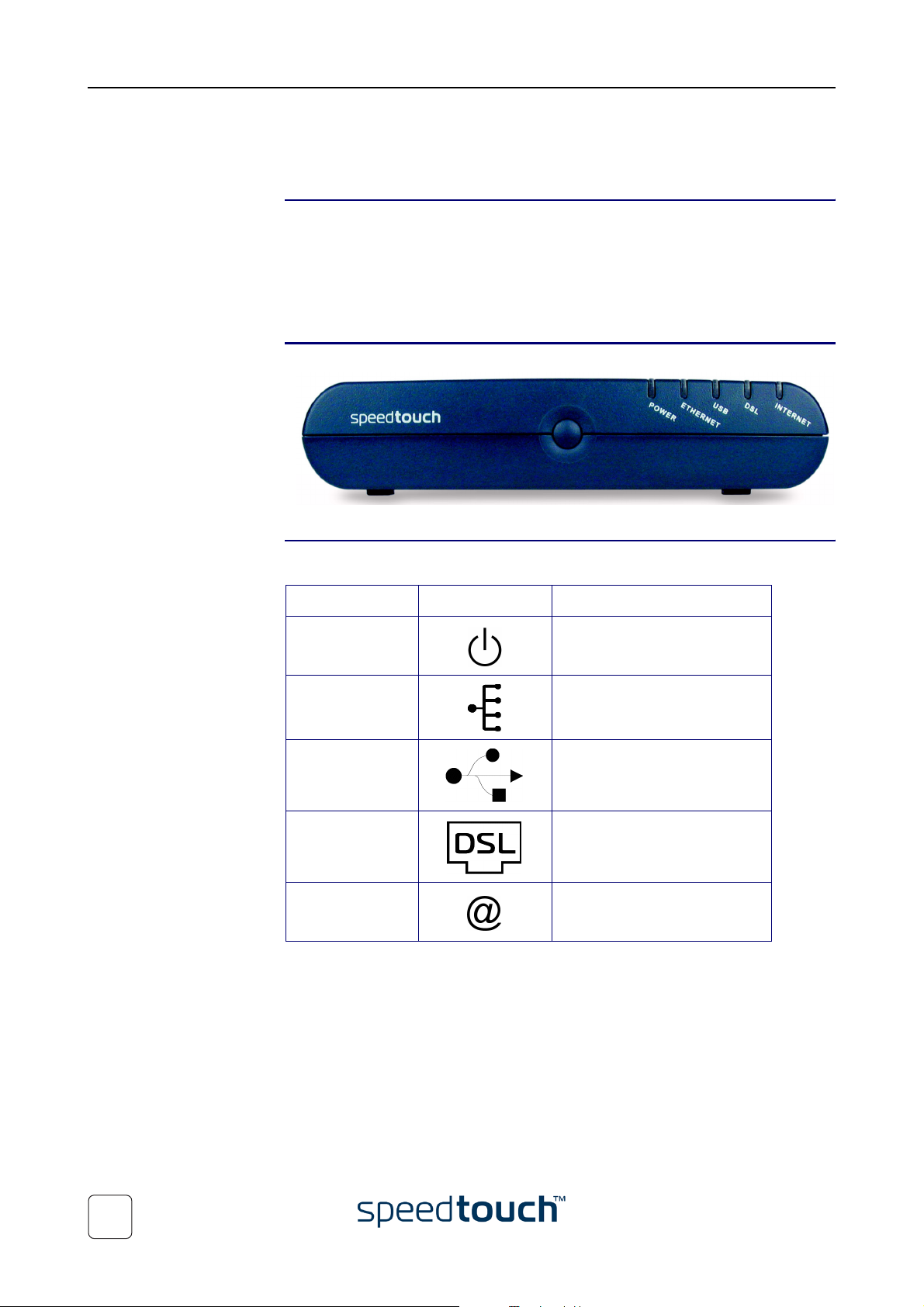
Front panel layout Your SpeedTouch™is presented in a desktop housing box:
Front panel LEDs A set of LEDs is provided to overview the SpeedTouch™ status:
LED indicator LED logo Description
Power Power/System status LED
Ethernet LAN link/activity LED
USB (if present) USB link/activity LED
DSL DSL synchronization LED
Internet WAN/Internet connection LED
Note The USB LED is available on the SpeedTouch™360(i) product only.
6
E-DOC-CTC-20031204-0011 v2.0
Page 9

1 SpeedTouch™ Installation
LED functionality The functionality of the LEDs is described in the table below:
Indicator Description
Name Color Status
Power Off Power off
Green Solid Power on, normal operation
Ethernet Off No Ethernet link
Green Solid Ethernet link, no LAN activity
Flashing Ethernet link, LAN activity
USB (if present) Off No USB link
Green Solid USB link, no activity
Flashing USB link, activity
DSL Off No DSL line
Green Flashing Pending DSL line synchronization
Solid DSL line synchronized
Internet Off No WAN connection, due to either:
• no DSL line synchronization
• no Bridged Ethernet interface
Green Solid WAN/Internet IP connected, no
activity (upstream nor downstream)
Flashing WAN/Internet IP connected, traffic
is passing (upstream and/or downstream)
E-DOC-CTC-20031204-0011 v2.0
7
Page 10
1 SpeedTouch™ Installation
A
A
C
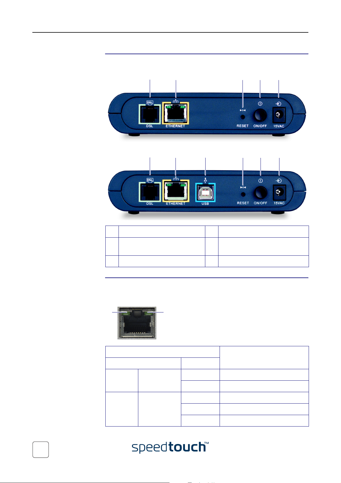
Back panel layout Depending on the product you purchased, your SpeedTouch™ is equipped with:
•
A single 10/100Base-T Ethernet port:
B
D E F
Ethernet port LED
functionality
• A single 10/100Base-T Ethernet port and a USB port:
B
D E F
A DSL line port (marked grey) D Recessed Reset button
B 10/100Base-T Ethernet port
EPower button
(marked yellow)
C USB port (marked blue) F Power inlet
The yellow marked Ethernet port on the rear panel has one LED to indicate the
connection integrity (activity). Depending on the SpeedTouch™ product you are using,
a second LED may be provided to indicate the 10/100Base-T selection:
BA
Indicator Description
Name LED Status
A
(Optional)
B Integrity
10/100Base-T Off 10Base-T Ethernet connection.
On 100Base-T Ethernet connection.
Off No connection on this port.
(Activity)
On Ethernet link up.
8
Flashing Data is flowing from/to this port.
E-DOC-CTC-20031204-0011 v2.0
Page 11

1.2 Setting up your SpeedTouch™
SpeedTouch™ variants Two ADSL variants of the SpeedTouch™ exist:
• The ADSL/POTS variant connecting to an analog Plain Old Telephone Service
(POTS) line
• The ADSL/ISDN variant connecting to a digital Integrated Services Digital
Network (ISDN) line
You can easily identify your variant by checking the identification label located on the
bottom of your SpeedTouch™.
Use only the SpeedTouch™ variant which is appropriate for the DSL service provided
to your premises. Check with your Service Provider to determine whether your SpeedTouch™ is adapted to ADSL service requirements.
ADSL service The appropriate DSL service must be available at your premises:
• ADSL service must be enabled on your telephone line.
1 SpeedTouch™ Installation
• As both telephone and ADSL service are simultaneously available from the same
copper pair, you will need a central splitter or distributed filters for decoupling
ADSL and telephone signals.
Always contact your Service Provider when installing splitters/filters! Public telephone
lines carry voltages that can cause electric shock. Only install splitter/filters yourself if
these are qualified for that purpose. Other splitter/filters may only be installed by qualified service personnel.
Connect the DSL line The grey DSL port on the SpeedTouch™ is marked .
Use the grey DSL cable provided to wire the SpeedTouch™ DSL port to your telephone wall outlet or distributed filter.
Connect the power
supply
Turn on the
SpeedTouch™
Always check first whether the power supply adapter provided is suitable for the local
power specifications. Contact your Service Provider in case of any doubt.
The power inlet on the SpeedTouch™ is marked .
Plug the adapter's coaxial jack into the SpeedTouch™'s power inlet and plug the power
supply into a power socket outlet.
Once all previous steps are completed, you can turn on the SpeedTouch™ with the
power button located on the SpeedTouch™ rear panel.
• Push in the button to switch on the SpeedTouch™.
• Push to release the button to switch off the SpeedTouch™.
Connecting your
computer(s)
E-DOC-CTC-20031204-0011 v2.0
Depending on the SpeedTouch™ variant you have, various solutions are available to
connect your computer(s) to the device. Proceed with “1.3 SpeedTouch™ Local
Network Setup” on page 10.
9
Page 12

1 SpeedTouch™ Installation
1.3 SpeedTouch™ Local Network Setup
Introduction Depending on the SpeedTouch™ variant you have, various solutions are available to
connect your computer(s) to the device:
• The SpeedTouch™350(i) supports Ethernet connectivity only
• The SpeedTouch™360(i) supports both Ethernet connectivity and USB connec-
tivity simultaneously.
Ethernet connectivity Ethernet connectivity is Operating System independent. It can even be used for simulta-
neously connecting multiple computers running various Operating Systems.
See “1.3.1 Ethernet Connection Setup” on page 11 for more information.
USB connectivity The SpeedTouch™360(i) USB port allows you to connect one computer to the Speed-
Touch™ via its USB port. This scenario may be useful in case your computer is not
equipped with an Ethernet port
USB connectivity is supported for following Operating Systems:
• Microsoft Windows OSs
• MS Windows 98/98SE
• MS Windows Millennium
• MS Windows 2000
• MS Windows XP
Before being able to connect to the SpeedTouch™ through the USB connection you
must first install USB drivers. Proceed with “1.3.2 USB Connection Setup for Microsoft
Windows” on page 12.
10
E-DOC-CTC-20031204-0011 v2.0
Page 13

1 SpeedTouch™ Installation
1.3.1 Ethernet Connection Setup
Note This section is applicable for both the SpeedTouch™350(i) and the SpeedTouch™360(i)
products.
Local network The SpeedTouch™’s yellow marked 10/100Base-T autosensing MDI/MDI-X Ethernet
port on the rear panel allows you to connect the SpeedTouch™ to an existing 10 or
100Base-T Ethernet network or a single computer with installed Ethernet card.
Note In the SpeedTouch™ package, a yellow full-wired straight-through RJ45/RJ45
Ethernet cable is included to connect a single computer to your SpeedTouch™.
You will need an external Ethernet hub or switch and the appropriate Ethernet cables
to connect multiple computers.
Standard wiring
procedure
Ethernet link check The SpeedTouch™ LED indicators allow you to check your Ethernet.
Use the Ethernet cable provided to wire your computer's Ethernet port to the SpeedTouch™'s Ethernet port.
If needed, you can use the yellow Ethernet cable included to wire any Ethernet port of
the Ethernet hub or switch to the SpeedTouch™’s Ethernet port.
Note If an external hub or switch is used for Ethernet networking, please follow
the installation instructions supplied with the hub or switch for connections
and Ethernet cabling.
See “1.1 Getting Acquainted with your SpeedTouch™” on page 6 for more information.
E-DOC-CTC-20031204-0011 v2.0
11
Page 14

1 SpeedTouch™ Installation
1.3.2 USB Connection Setup for Microsoft Windows
Note This section is only applicable for the SpeedTouch™360(i) product when connecting a
PC (running an MS Windows OS) through the device’s USB port.
Supported Operating
Systems
System requirements • For Windows 98/98SE/ME:
Installing and using the SpeedTouch™ USB connection is supported for following
Microsoft Operating Systems:
• MS Windows 98/98SE
• MS Windows Millennium
• MS Windows 2000
• MS Windows XP
You may need the Windows installation CD-ROM during installation.
Note The installation procedures might be slightly different depending on the MS
Windows OS you are using:
• Pentium processor 166 MHz or compatible
• 32 megabytes (MB) of memory
• For Windows 2000/XP:
• Pentium II processor or compatible
• 64 MB of memory
• 30 MB of free disk space
Prerequisites Make sure to remove any SpeedTouch™ USB driver installation that may reside on your
PC before you install the USB drivers from the SpeedTouch™ Setup CD-ROM delivered with your SpeedTouch™360(i) product.
Make sure both your PC and SpeedTouch™ are turned on and operational.
Installing the
SpeedTouch™ USB
connection
The installation is Plug and Play, meaning that installation will require almost no effort.
Proceed as follows
1 Insert the USB cable provided into the SpeedTouch™ USB port marked with the
USB logo: .
2 The other end of the USB cable fits in (one of) the USB port(s) of your PC. In
most cases your PC's USB port is marked with the same USB symbol.
Note You can also connect your PC to the SpeedTouch™ via a USB hub.
12
E-DOC-CTC-20031204-0011 v2.0
Page 15
1 SpeedTouch™ Installation
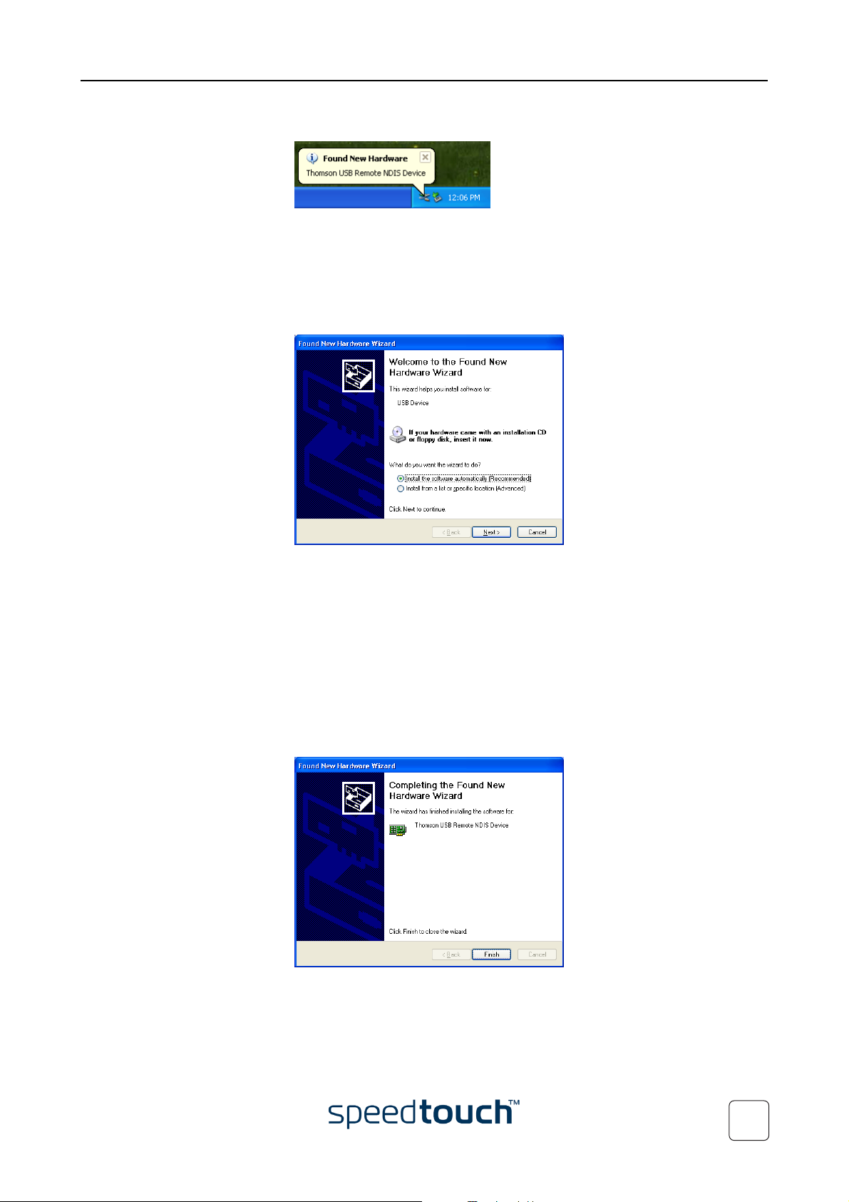
3 Windows will automatically recognize the THOMSON USB Remote NDIS device:
4 The Windows Found New Hardware Wizard appears:
This wizard will guide you through the installation procedure of the SpeedTouch™
USB drivers.
Click Next to continue.
5 The following windows of the Found New Hardware Wizard allow you to select
locations where it should search for drivers:
Insert the SpeedTouch™ Setup CD-ROM, make sure that the wizard looks for the
drivers on the CD-ROM drive and click Next to continue.
6 The wizard will notify that it found drivers for the THOMSON USB Remote NDIS
device on the CD-ROM.
Click Next to continue.
7 The installation procedure continues with the installation of the USB Remote
NDIS drivers.
8 In the following windows you can follow the installation procedure. Click Next
whenever requested to continue the installation.
9 At the end of the procedure, the following window appears:
E-DOC-CTC-20031204-0011 v2.0
Click Finish to complete the installation.
10 As a result your USB connection is installed and ready for use.
13
Page 16
1 SpeedTouch™ Installation
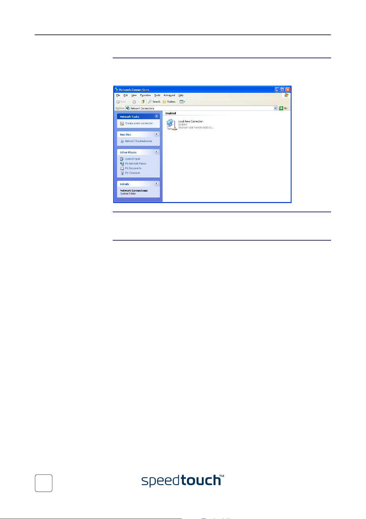
Verifying USB
connectivity
Connecting another
computer
The SpeedTouch™360 USB connection is represented as a local network interface. You
can easily check this interface by opening the Network Connections window from
Windows’s Control Panel:
Optionally you can connect another computer, using the SpeedTouch™360 Ethernet
port.
Connecting to the
Internet
In most cases no additional configuration of your SpeedTouch™ is required. You can
immediately connect your computer to the Internet (see “2 SpeedTouch™ Internet
Connectivity” on page 15).
14
E-DOC-CTC-20031204-0011 v2.0
Page 17

2 SpeedTouch™ Internet Connectivity
2 SpeedTouch™ Internet Connectivity
Introduction This chapter provides information on how to access the Internet via your Speed-
Touch™.
Once the SpeedTouch™ has been installed and the computers prepared as outlined in
“1 SpeedTouch™ Installation” on page 5, you are ready to connect to the Internet.
Access methods Depending on your Service Provider’s Internet Service requirements you may have:
• Direct access
As soon as the initial installation of the SpeedTouch™ and preparation of your
computer has been done, continuous and immediate Internet/WAN access is
available via the SpeedTouch™.
• Dial-in access
Internet/WAN access must be explicitly established, e.g. by “dialing” into
a Broadband Remote Access Server (BRAS) via a dial-in application on your
computer.
See “2.1 Connect to the Internet via a Host PPPoE Dial-in Client” on page 16 for
more information.
The method used depends on the Service Provider's requirements.
SpeedTouch™ Internet
configuration
Your Internet
connection
Your SpeedTouch™ has been prepared for providing the appropriate Internet services
out of the box, meaning that in the very most cases no specific configuration of the
device needs to be done.
By default following Internet services are readily available:
• Virtual Channel (VC) - VPI/VCI=0/35 (ETHoA, LLC/snap - Bridged Ethernet)
• Virtual Channel (VC) - VPI/VCI=8/35 (ETHoA, LLC/snap - Bridged Ethernet)
• Virtual Channel (VC) - VPI/VCI=1/101 (ETHoA, LLC/snap - Bridged Ethernet)
• Virtual Channel (VC) - VPI/VCI=1/32 (ETHoA, LLC/snap - Bridged Ethernet)
• Virtual Channel (VC) - VPI/VCI=0/100 (ETHoA, LLC/snap - Bridged Ethernet)
• Virtual Channel (VC) - VPI/VCI=8/48 (ETHoA, LLC/snap - Bridged Ethernet)
• Automatic Permanent Virtual Channel (PVC) configuration (if supported by the
Telephone Operator/Service Provider)
Note Bridged Ethernet is also referred to as (IEEE802.1b Transparent) Bridging.
In case your Service Provider instructs you to use an Internet service, other than the
ones listed above (i.e. another Virtual Channel needs to be applied for Bridged
Ethernet), please see “4.1 SpeedTouch™ Configuration Setup” on page 34.
Regardless of whether a direct access or a dial-in access method is used to make your
connection, once the connection is established, opening your web browser is enough to
access the World Wide Web (WWW) or Internet.
E-DOC-CTC-20031204-0011 v2.0
Note In case of direct access, the remote organization might ask for a user name
and password on an Internet welcome page.
15
Page 18

2 SpeedTouch™ Internet Connectivity
2.1 Connect to the Internet via a Host PPPoE Dialin Client
Introduction This section explains how you can connect to the Internet using a Broadband PPPoE
dial-in application. The PPP over Ethernet connection scenario provides PPP-like dial-in
behavior over the virtual Ethernet segment.
BroadBand dial-in
clients
To connect to the Internet you can use:
• An MS Windows XP broadband dial-in client.
See “2.1.1 Using an MS Windows XP BroadBand Connection.” on page 17 for
more information.
• A Mac OS X broadband dial-in client (Ethernet connectivity only).
See “2.1.2 Using the Mac OS X PPPoE Dial-in Client” on page 21 for more infor-
mation.
- or -
• A broadband PPPoE dial-in client provided by your Service Provider to connect to
the Internet
Note Required for PPPoE session connectivity in case of
MS Windows 98(SE), MS Windows ME, MS Windows 2000 and
Mac OS 8.6/9.x.
16
E-DOC-CTC-20031204-0011 v2.0
Page 19

2 SpeedTouch™ Internet Connectivity
2.1.1 Using an MS Windows XP BroadBand Connection.
Configuring a
broadband connection
Proceed as follows:
1 On the Start menu, click (Settings >) Control Panel.
2 The Control Panel window appears. Go to (Network and Internet Connections >)
Network Connections.
3 In the Network Tasks menu, click Create a new connection.
The New Connection Wizard appears:
Click Next to continue.
4 In the next window, select Connect to the Internet:
E-DOC-CTC-20031204-0011 v2.0
Click Next to continue.
5 In the next window, select Set up my connection manually:
Click Next to continue.
17
Page 20

2 SpeedTouch™ Internet Connectivity
6 In the next window, select Connect using a broadband connection that requires a user
name and password:
Click Next to continue.
7 In the next window, give a name to the connection you are creating, e.g. MyISP:
8 In the next window, select whether the connection is available to any user or only
to yourself:
Note If you want to share this connection with other users you must select
Anyone’s use.
9 In the next window, fill in the Internet account information. This information
should be provided by your service provider:
18
E-DOC-CTC-20031204-0011 v2.0
Page 21

2 SpeedTouch™ Internet Connectivity
10 At the end of the configuration the following window appears:
Click Finish to complete the configuration.
The Connect MyISP window (see below) appears.
Starting a broadband
Internet session
Proceed as follows:
1 On the Start menu, point Connect To and click the name of the connection you’ve
created e.g. MyISP.
Note If you are using the classic Start menu click Start > Settings > Network
(and Dial-up) connections > MyISP.
2 The Connect MyISP window appears:
3 If needed, enter user name and password for your user account at the Service
Provider.
4 Click Connect.
5 As soon as the connection is established, the connection message box and dial-up
window are minimized into a DUN icon in the notification area:
E-DOC-CTC-20031204-0011 v2.0
You can open your web browser and surf the Internet.
19
Page 22

2 SpeedTouch™ Internet Connectivity
Terminating a
broadband Internet
session
Proceed as follows:
1 On the Start menu, point Connect To and click the name of the connection you’ve
created e.g. MyISP.
Note If you are using the classic Start menu go to Start > Settings >
Network (and Dial-up) connections > MyISP.
2 The MyISP Status window appears:
3 Click Disconnect.
The connection is released. As a result no Internet connectivity exists anymore.
20
E-DOC-CTC-20031204-0011 v2.0
Page 23

2 SpeedTouch™ Internet Connectivity
2.1.2 Using the Mac OS X PPPoE Dial-in Client
Configuring a
broadband connection
Proceed as follows:
1 On the Apple menu, click System Preferences.
2 The System Preferences window appears. Click the Network icon.
3 The Network window appears. Make sure Built-in Ethernet is selected in the Show
list and click the PPPoE tab:
4 Enter the Account Name and Password provided by your Service Provider.
Note Select Save password in case you want the computer to remember the
password for this account name.
Optionally you can enter a name for this connection in the Service
Provider field. All other fields may stay empty
5 Click Apply Now.
E-DOC-CTC-20031204-0011 v2.0
21
Page 24

2 SpeedTouch™ Internet Connectivity
Starting a broadband
Internet session
Proceed as follows:
1 Click the Internet Connect dockling.
Note If the Internet Connect dockling is not available, go to the Applications
folder on the system startup disk and double-click Internet Connect.
2 The following window appears:
Make sure Built-in Ethernet is selected in the Configuration list.
3 If needed, enter user name and password for your user account at the Service
Provider.
4 Click Connect.
As soon as the connection is established you can open your web browser and surf the
Internet.
Terminating a
broadband Internet
session
Proceed as follows:
1 Click the Internet Connect dockling.
Note If the Internet Connect dockling is not available, go to the Applications
folder on the system startup disk and double-click Internet Connect.
2 The following window appears:
Make sure Built-in Ethernet is selected in the Configuration list
3 Click Disconnect.
The connection is released. As a result no Internet connectivity exists anymore.
22
E-DOC-CTC-20031204-0011 v2.0
Page 25

3 SpeedTouch™ Web Interface
3 SpeedTouch™ Web Interface
Introduction The SpeedTouch™ comes with integrated configuration web pages.
It allows you to configure your SpeedTouch™ simply by using a web browser from any
local computer attached to the SpeedTouch™.
Preconditions Before you can access the SpeedTouch™ web pages, you must make sure that:
• The SpeedTouch™ and your computer share the same IP subnet (10.0.0.0/24).
By default the SpeedTouch™ has a local IP address 10.0.0.138
access the web pages, your computer needs to be configured for an IP address in
the same subnet, e.g. 10.0.0.1.
• Your web browser is not using a proxy server and the SpeedTouch™ IP address is
not submitted to a proxy server
To configure your computer with an IP address, please consult the Operating System’s
Help. For more information on how to disable your web browser's proxying, please
consult the web browser's Help.
. To be able to
Browsing to the
SpeedTouch™ web
pages
The SpeedTouch™
Start page
To access the SpeedTouch™ web pages:
1 Start the web browser on your computer.
2 Browse to the SpeedTouch™ web pages at its IP address at 10.0.0.138
Note 10.0.0.138
cases. If not, please contact your Service Provider for more information.
3 If a system password has been set, an authentication window will be displayed. You
must enter the user name and system password before access will be granted.
As a result the System Information page appears:
is the SpeedTouch™ default IP address in the very most
.
E-DOC-CTC-20031204-0011 v2.0
23
Page 26

3 SpeedTouch™ Web Interface
Topic menu and links On the left of each of the SpeedTouch™ web pages a topics menu is provided. This
menu navigates you via links through all configurational aspects of the SpeedTouch™.
For your convenience the links are sorted in two drop-down topics menus: Basic and
Advanced. The links in the Basic topic menu lead you to pages for basic SpeedTouch™
configuration and maintenance. The Advanced topic menu, contains the links which
allow advanced configuration of the SpeedTouch™. These pages need only to be
accessed for some specific operations, when instructed by the Service Provider.
The following table lists all Basic topic links:
BASIC topic menu
Click ... To ...
System Information The SpeedTouch™ Start Page
View the device’s system status and service profile
View the current ADSL line status.
Easy Setup Configure the SpeedTouch™ via the embedded wizard.
System Password Set a system password.
The following table lists all advanced topic links:
ADVANCED topic menu
Click ... To ...
Diagnostics View SpeedTouch™ diagnostics.
System Log View the activity on the SpeedTouch™ since power on.
IP Addresses View/configure the SpeedTouch™ IP interfaces.
DHCP View/configure the SpeedTouch™ DHCP server/client.
DNS View/configure the SpeedTouch™ DNS server/client.
System Manage system and configuration.
Language Configure the web page language.
Save all The Save All link on the menu allows you to save the SpeedTouch™ settings. You should
use this link whenever you have made definitive changes to the SpeedTouch™ configuration.
24
Help The Help link in the topics menu header allows you to browse the SpeedTouch™
online Help.
For more information on a specific topic you can click the context-related Help links located at the Topic's web pages.
E-DOC-CTC-20031204-0011 v2.0
Page 27

3 SpeedTouch™ Web Interface
3.1 Basic Topics Menu Links
System Information Click this link to display the System Information page. This page is also the Speed-
Touch™ home page.
The System Information page consists of four sections:
• Click the Diagnostics tab to view the results of the System Self Test, LAN connec-
tivity and DSL synchronization test:
• Click the Service Info tab to view the current physical status of the ADSL line:
The DSL Statistics allow you to view:
• Line Status: this shows whether the DSL link is synchronized (Enabled) or
not (Initializing).
• Bandwidth Up/Down: the maximum available bandwidth of the DSL link in
both up- and downstream direction.
• Uptime: The duration of the current Enabled Line Status.
• Click the Configuration tab to view the service configuration currently active on the
SpeedTouch™. In most cases this will be the factory defaults configuration:
• Click the System tab to view some important device and system software informa-
tion of your SpeedTouch™:
E-DOC-CTC-20031204-0011 v2.0
Note Most device information can also be found on the identification label at
the bottom of the SpeedTouch™.
25
Page 28

3 SpeedTouch™ Web Interface
Easy Setup Click this link to start the SpeedTouch™ Easy Setup wizard.
See “4.1.2 Operating System Independent SpeedTouch™ Configuration Setup” on
page 41 for more information.
System Password Click this link to display the System Password page.
This page allows you to configure a system password to restrict access to the SpeedTouch™:
It is highly recommended to configure a system password, to protect the SpeedTouch™. Make sure however not to use an obvious password such as your name, date
of birth, etc.
Enter User id and Password (maximum 16 characters) of your choice and re-enter your
password in the appropriate field. Click Apply to apply the System password and Save all
to save your changes to persistent memory.
Note As long as no system password is supplied, a warning is displayed on the
SpeedTouch™ web pages.
26
E-DOC-CTC-20031204-0011 v2.0
Page 29

3.2 Advanced Topics Menu Links
Diagnostics Click this link to display the Diagnostics page.
This page consists of three expandable sections:
• Expand the System section to view some important system information:
• Expand the Lan section to view the LAN configuration:
3 SpeedTouch™ Web Interface
• Expand subsequently the Wan and DSL sections to view the current DSL state
and connection information:
E-DOC-CTC-20031204-0011 v2.0
27
Page 30

3 SpeedTouch™ Web Interface
System Log Click this link to view the System Log page.
This page allows you to view the activity on the SpeedTouch™ since power on:
IP Addresses Click this link to display the IP Addresses page.
This page allows you to view the SpeedTouch™ local IP address configuration:
If needed you are able to assign one or more additional IP addresses to the SpeedTouch™ Ethernet interface (identified as eth0), e.g. for purposes of multi-homing.
You can also delete superfluous IP addresses. However be aware that you cannot delete
the SpeedTouch™ IP address which you are currently using.
DHCP Click this link to display the Dynamic Host Configuration Protocol (DHCP) page.
• Click the DHCP Server tab to access the DHCP server pages.
• The Server Config tab allows you to enable/disable the SpeedTouch™
(Auto)DHCP server:
28
By default (as shown above) the SpeedTouch™ DHCP server will be
disabled.
E-DOC-CTC-20031204-0011 v2.0
Page 31

3 SpeedTouch™ Web Interface
If required, you are able to select:
• DHCP server
Enables the SpeedTouch™ DHCP server. If it was not running, it will
be started immediately.
• Auto DHCP
The SpeedTouch™ will not start as DHCP server immediately, but will
first probe the network for a possible concurrent DHCP server for
some period of time (set by Client timeout in seconds).
As soon as another DHCP server is found, the SpeedTouch™ will
behave as DHCP client, i.e. a DHCP client will be created on its
Ethernet interface and the SpeedTouch™ DHCP server will not be
started.
If no concurrent DHCP server is found, the SpeedTouch™ DHCP
server is started.
• No DHCP
Disable SpeedTouch™ DHCP configuration.
If the SpeedTouch™ DHCP server was running, it will be stopped
immediately.
Existing SpeedTouch™ DHCP client entries are deleted
Note Always click Apply after changing the DHCP server configuration.
• In case the SpeedTouch™ DHCP server is running, the Server Leases tab
allows you to view the currently provided leases.
If needed, you can also manually add static DHCP leases for specific hosts.
To make dynamically assigned leases static, select the entry and click Lock.
• The Address Pools tab allows you to view the SpeedTouch™ DHCP server
lease pool properties. One DHCP pool (LAN_Private) is defined by default
which will be activated if you enable the SpeedTouch™ DHCP server.
• Click the DHCP Client tab to view the current SpeedTouch™ DHCP client
entries, if present:
By default (as shown above) the SpeedTouch™ DHCP client will be disabled, i.e.
no DHCP client entries are present.
E-DOC-CTC-20031204-0011 v2.0
29
Page 32

3 SpeedTouch™ Web Interface
DNS Click this link to display the Dynamic Name System (DNS) page.
This page allows you to:
• View the current SpeedTouch™ DNS server hostname leases:
Via this table you can also add static DNS hostname entries.
This may be useful for devices which do not support DNS, e.g. a printer. By adding
a name for your network printer, identified by its IP address, you will be able to
contact this printer by name rather than by IP address.
• View and/or supply the SpeedTouch™ DNS domain name and to enable/disable
the SpeedTouch™ DNS server:
Note The use of DNS subdomains is supported, e.g. dsl.office.lan.
System Click this link to display the Configuration page.
• Back up the current SpeedTouch™ configuration, restore the SpeedTouch™
default configuration, or upload a backup configuration file:
30
• To backup the current configuration click Backup and follow the instructions.
• To restore the SpeedTouch™ defaults, click Restore default and follow the
instructions to confirm the reset.
E-DOC-CTC-20031204-0011 v2.0
Page 33

3 SpeedTouch™ Web Interface
• To upload and apply a SpeedTouch™ backup configuration file:
1 Click Browse to locate the backup file on your local disk you intend to
restore. Select the file and click OK.
2 Click Upload to upload and temporarily apply the backup configuration.
3 Once uploaded, the SpeedTouch™ asks you to confirm that you want
the SpeedTouch™ to effectively apply the uploaded configuration.
Click Accept to save the new configuration.
Note Once confirmed, the previous configuration is irrevocably
lost.
• View the current system software version, identification and the SpeedTouch™
board type:
• Check for the latest SpeedTouch™ software upgrades.
Note See “4.2 SpeedTouch™ System Software Upgrade” on page 44 for upgrade
instructions.
Language Click this link to view the Language page.
This page allows you to select the SpeedTouch™ web page language.
By default, the only available language is English.
Another language can be made available on the SpeedTouch™ web pages by running the
SpeedTouch™ Setup wizard using the CD Browser.
At the start of the setup procedure, select the desired language. When the setup procedure is finished, this language will have been enabled on your SpeedTouch™ and the
language will be available on the SpeedTouch™ web pages (next to English).
E-DOC-CTC-20031204-0011 v2.0
31
Page 34

3 SpeedTouch™ Web Interface
32
E-DOC-CTC-20031204-0011 v2.0
Page 35

4 Support
In this chapter This chapter contains the following topics:
Topic Page
SpeedTouch™ Configuration Setup 34
SpeedTouch™ System Software Upgrade 44
Resetting the SpeedTouch™ 52
Troubleshooting 53
4 Support
E-DOC-CTC-20031204-0011 v2.0
33
Page 36

4 Support
4.1 SpeedTouch™ Configuration Setup
Internet connectivity In most cases no additional configuration of your SpeedTouch™ is required. You can
immediately connect your computer to the Internet as described in “2 SpeedTouch™
Internet Connectivity” on page 15).
SpeedTouch™ Internet
configuration
What you need from
your ISP
Your SpeedTouch™ has been prepared for providing the appropriate Internet services
out of the box, meaning that in the very most cases no specific configuration of the
device needs to be done.
By default following Internet services are readily available:
• Virtual Channel (VC) - VPI/VCI=0/35 (ETHoA, LLC/snap - Bridged Ethernet)
• Virtual Channel (VC) - VPI/VCI=8/35 (ETHoA, LLC/snap - Bridged Ethernet)
• Virtual Channel (VC) - VPI/VCI=1/101 (ETHoA, LLC/snap - Bridged Ethernet)
• Virtual Channel (VC) - VPI/VCI=1/32 (ETHoA, LLC/snap - Bridged Ethernet)
• Virtual Channel (VC) - VPI/VCI=0/100 (ETHoA, LLC/snap - Bridged Ethernet)
• Virtual Channel (VC) - VPI/VCI=8/48 (ETHoA, LLC/snap - Bridged Ethernet)
• Automatic Permanent Virtual Channel (PVC) configuration (if supported by the
Telephone Operator/Service Provider)
Note Bridged Ethernet is also referred to as (IEEE802.1b Transparent) Bridging.
However, in case your Service Provider instructs you to use an Internet service, other
than the ones listed above (i.e. another Virtual Channel needs to be applied for Bridged
Ethernet), the SpeedTouch™ offers the SpeedTouch™ Setup wizard, allowing you to
create a customized Internet service.
In case reconfiguration is needed, you must have:
• The Virtual Path Identifier (VPI) and Virtual Channel Identifier (VCI) for the
Virtual Channel (VC) to use.
For example: VPI/VCI = 9/99
34
• The ATM encapsulation method to use for encapsulating/un-encapsulating
Ethernet frames over ATM. This will either be:
• LLC/SNAP
• VC-MUX
• Optionally, a user account with an Internet Service Provider (ISP) for Internet
access. For this user account, it will provide you with:
• A user name (logon ID)
• A password
Other information may be required, depending on the ISP's specific requirements.
E-DOC-CTC-20031204-0011 v2.0
Page 37

4 Support
Configuration of the
SpeedTouch™
Depending on your computer's Operating System (OS) the configuration of your
Internet connectivity can be done automatically or manually.
If your computer runs:
•
A Microsoft Windows OS.
The SpeedTouch™ Setup wizard, included on the SpeedTouch™ Setup CD-ROM,
will automatically guide you through the configuration of both the SpeedTouch™
and your PC for setting up the appropriate configuration.
Proceed with “4.1.1 Microsoft Windows SpeedTouch™ Configuration Setup” on
page 36.
•
Another OS, e.g. Mac OS, Unix, Linux.
The SpeedTouch™ Embedded Easy Setup wizard, accessible from the SpeedTouch™ web pages, will automatically guide you through the configuration of the
SpeedTouch™.
Proceed with “4.1.2 Operating System Independent SpeedTouch™ Configuration
Setup” on page 41.
E-DOC-CTC-20031204-0011 v2.0
35
Page 38

4 Support
4.1.1 Microsoft Windows SpeedTouch™ Configuration Setup
Microsoft Windows One of the following Windows operating systems must already be installed on your
PC(s):
• Windows 98
• Windows 98SE
• Windows ME
• Windows NT4.0 SP6 (Ethernet only)
• Windows 2000
• Windows XP
You may need the Windows installation CD-ROM during installation.
36
E-DOC-CTC-20031204-0011 v2.0
Page 39

3 The SpeedTouch™ CD Browser appears:
Click Setup my SpeedTouch™ to start the SpeedTouch™ Setup wizard.
4 The Welcome to the SpeedTouch™ Setup Wizard window appears:
4 Support
Click Next.
5 The Software License Agreement window appears:
You must accept before continuing. Click Yes to accept.
Note If you have accepted this License Agreement in a previous configura-
tion setup, this window will not be shown anymore.
E-DOC-CTC-20031204-0011 v2.0
37
Page 40

4 Support
6 The Setup wizard will search for the SpeedTouch™ on the network. The following
window shows the detection progress:
7 The Setup wizard should find your SpeedTouch™ device on the local network.
This is indicated by the following window:
If more than one device is found, a list of available devices will be provided. If this
is the case, select your SpeedTouch™ device (SpeedTouch™350 or SpeedTouch™360) and click Next.
Note If the wizard does not find any SpeedTouch™ on the network an error
window appears. In this case check that:
• The SpeedTouch™ is turned on and fully initialized.
• Your PC is correctly connected to the SpeedTouch™.
• Your PC has a valid IP address (i.e. any IP address but 0.0.0.0).
• No dedicated firewall device or router is placed between your
PC and the SpeedTouch™
• No personal firewall software is running on your PC.
• TCP/IP is correctly installed on your PC
8 To repeat the search for your SpeedTouch™, click Back and proceed with step 6
of this procedure.
9 Click Next to start the configuration procedure described below.
38
E-DOC-CTC-20031204-0011 v2.0
Page 41

4 Support
Configuration of the
SpeedTouch™ (and PC)
Proceed as follows:
1 As soon as the SpeedTouch™ Setup wizard has detected your SpeedTouch™
device, you can proceed with the configuration procedure.
Note If the SpeedTouch™ has been configured before:
• It may be protected by a system password. You must provide
user name and system password before you can view the device
details or continue with the configuration.
• You will be asked to choose between reconfiguring your Speed-
Touch™ or changing your Local Area Network configuration.
Select Reconfigure the SpeedTouch™ and click Next.
2 The following window invites you to select the appropriate service for your Inter-
net connectivity:
Select region, Provider and Service as specified by your Service Provider and click
Next to continue.
Note If the Service Provider has included a separate disk with a dedicated
service profile, click Have Disk to navigate to the location of the appropriate Service template file.
3 Subsequent screens will guide you through the configuration setup of both the
SpeedTouch™ and your PC. Follow the instructions and enter the required information whenever needed. The requested information will depend on the selected
Service profile and should be provided by your Service Provider.
Click Next whenever requested.
4 The SpeedTouch™ Setup wizard will update the SpeedTouch™ configuration and
your PC’s configuration according the Service profile. You can follow the configuration progress in following window:
E-DOC-CTC-20031204-0011 v2.0
39
Page 42

4 Support
5 As soon as the SpeedTouch™ Setup wizard completed the update of the Speed-
Touch™ configuration and reconfigured your PC, following window will appear:
Click Finish to close the wizard.
Note In some cases, the SpeedTouch™ Setup wizard may ask you to restart your
computer.
Additional configuration Some additional configuration may be needed:
• MS Windows IP configuration
Most Service profiles will configure the PC’s Ethernet interface to comply with the
service’s requirements.
To make sure that all PCs are configured as expected (e.g. DHCP or fixed IP
addresses):
1 Re-run the SpeedTouch™ Setup wizard on every PC.
2 Select Change the LAN configuration.
3 Follow the instructions.
Note For fixed IP configurations, or other advanced settings, please follow
the instructions provided by your ISP or network administrator.
40
E-DOC-CTC-20031204-0011 v2.0
Page 43

4 Support
4.1.2 Operating System Independent SpeedTouch™ Configuration Setup
Supported Systems As the SpeedTouch™ is OS-independent, this configuration setup can be used by any
computer system
Prerequisites Make sure that:
• The SpeedTouch™ device is correctly set up and turned on as described in
“1.2 Setting up your SpeedTouch™” on page 9.
• The SpeedTouch™ device is in its default configuration state.
See “4.3 Resetting the SpeedTouch™” on page 52 for resetting your device.
• The SpeedTouch™ and your computer share the same IP subnet (10.0.0.0/24).
By default the SpeedTouch™ has a local IP address 10.0.0.138
access the web pages, your computer needs to be configured for an IP address in
the same subnet, e.g. 10.0.0.1.
• Your web browser is able to run Java scripts.
. To be able to
SpeedTouch™
Easy Setup
SpeedTouch™ Easy Setup consists of two parts:
• Configuration of the SpeedTouch™
• Additional configuration (if needed)
E-DOC-CTC-20031204-0011 v2.0
41
Page 44

4 Support
Configuration of the
SpeedTouch™
Proceed as follows:
1 Open a web browser and browse to the SpeedTouch™ web pages at
http://10.0.0.138
. See “3 SpeedTouch™ Web Interface” on page 23 for more
information.
Note If you can not access the SpeedTouch™ web pages, it is probably not in
its default state. It is recommended to reset the device.
2 The embedded Easy Setup wizard will appear automatically:
Click Next.
Note If Easy Setup doesn’t start automatically go to
Basic > Easy Setup.
3 The following window invites you to select the appropriate Virtual Channel for
the Bridged Ethernet Service:
42
4 Subsequent screens will guide you through the configuration setup of the Speed-
Touch™. Follow the instructions and enter the required information whenever
needed. The requested information will depend on the selected Service and
should be provided by your Service Provider.
Click Next whenever requested.
E-DOC-CTC-20031204-0011 v2.0
Page 45

4 Support
5 Easy Setup will update the SpeedTouch™ configuration according to the Service
profile. You can follow the configuration progress in following window:
6 As soon as Easy Setup completed the update of the SpeedTouch™ configuration,
following window will appear:
Click Finish to close the wizard.
Note Due to the reconfiguration the SpeedTouch™’s IP configuration may
have been changed. If this is the case, the last window will not be
shown. If so refer to the Service Provider’s instructions for more information on the new IP configuration of the SpeedTouch™.
Additional configuration Some additional configuration may be needed:
• Computer IP configuration
The Service profile will configure the PC’s Ethernet interface to comply with the
service’s requirements.
Note For other advanced settings, please follow the instructions provided by
your Service Provider or network administrator.
E-DOC-CTC-20031204-0011 v2.0
43
Page 46

4 Support
4.2 SpeedTouch™ System Software Upgrade
Introduction This chapter describes how to upgrade the SpeedTouch™ system software.
System software
updates
System software
packages and security
System software
upgrades
For checking the availability of new system software version packages:
• Click the link, available on the SpeedTouch™ CD Browser.
• Contact your Network Administrator or your Service Provider
• Visit the SpeedTouch™ support pages at:
• http://www.speedtouch.com
All system software packages for the SpeedTouch™ are digitally signed and encrypted.
Packages that may have come corrupted, or been altered in any way, will not be
accepted by the SpeedTouch™.
This way, the SpeedTouch™, or its service can never be corrupted or lost.
Depending on the operating system your computer is running, you can upgrade your
SpeedTouch™ via:
• The SpeedTouch™ Upgrade Wizard (Microsoft Windows or Mac OS X).
See “4.2.1 Upgrade via the SpeedTouch™ Upgrade Wizard” on page 45 for more
information.
• The SpeedTouch™ BootP client (all Operating Systems).
See “4.2.2 Manual System Software Management via BOOTP Server” on page 50
for more information.
Preliminary steps Before you start with upgrading the SpeedTouch™, always make sure:
• To inform all people relying on the SpeedTouch™ services, that service may be
down for some short period.
• That the new system software file is stored on your local disk or another storage
device.
44
E-DOC-CTC-20031204-0011 v2.0
Page 47

4.2.1 Upgrade via the SpeedTouch™ Upgrade Wizard
Introduction The procedure described in this section are valid only in case:
• You run an MS Windows Operating System or Mac OS X.
• Your SpeedTouch™ and computer are properly connected:
• Through Ethernet or USB in case you run an MS Windows OS
• Through Ethernet in case you run Mac OS X
• The new system software file is of the type bant-f_XX42xx.bin,
e.g. bant-f_AA4279.bin.
During the upgrade procedure all configuration settings are backed up by the wizard
and restored after uploading the system software.
4 Support
Starting the
SpeedTouch™ Upgrade
wizard
On MS Windows
Operating Systems
Depending on your Operating System, you must start the SpeedTouch™ Upgrade
wizard as follows:
Topic Page
On MS Windows Operating Systems 45
On Mac OS X 46
Proceed as follows:
1 Insert the SpeedTouch™ Setup CD-ROM in your PC's CD-ROM drive. The
SpeedTouch™ CD Browser will start automatically.
Note If the SpeedTouch™ CD Browser window does not appear automati-
cally, open a Run window via Start > Run from the Start menu and
enter following path: D:\Menu.exe, where D is the drive letter of your
CD-ROM drive.
2 The Choose Language window prompts you to select a language.
Select the language of your choice and click OK.
Note The selected language will also be used as default language in the
SpeedTouch™ web pages. See “ Language” on page 31 for more information on how to change the web page language.
E-DOC-CTC-20031204-0011 v2.0
45
Page 48

4 Support
3 The SpeedTouch™ CD Browser menu appears:
Click Diagnostics & Maintenance.
4 The following window appears:
Click Upgrade My SpeedTouch™ to start the SpeedTouch™ Upgrade wizard.
See “ Upgrade procedure” on page 47 to continue.
On Mac OS X Proceed as follows:
1 Insert the SpeedTouch™ Setup CD-ROM in your PC's CD-ROM drive.
2 Open the CD-ROM and browse to the osx folder.
3 In the osx folder double-click upgradeST.pkg to install the SpeedTouch™ Upgrade
application.
Note The installation wizard may prompt you for authentification. If this is
the case, click
Note If your computer runs Mac OS X v10.3, your computer may prompt
you to run a program to determine if the installer package can be
installed. If this the case, click Continue.
4 After installation go to the Applications > Speedtouch folder on the system startup
disk (usually the location where you installed the SpeedTouch™ Upgrade application) and double-click SetupST. to start the SpeedTouch™ Upgrade wizard.
5 The Choose Language window prompts you to select a language.
Select the language of your choice and click OK.
Note The selected language will also be used as default language in the
SpeedTouch™ web pages. See “ Language” on page 31 for more information on how to change the web page language.
See “ Upgrade procedure” on page 47 to continue.
to enter your credentials.
46
E-DOC-CTC-20031204-0011 v2.0
Page 49

Upgrade procedure Proceed a follows:
1 The Welcome to the SpeedTouch™ Upgrade Wizard window appears:
Click Next.
2 The SpeedTouch™ Software License Agreement window appears:
4 Support
You must accept before continuing. Click Yes to accept.
Note If you have accepted this License Agreement in a previous configura-
tion setup, this window will not be shown anymore.
3 The Setup wizard will search for the SpeedTouch™ on the network. The following
window shows the detection progress:
E-DOC-CTC-20031204-0011 v2.0
47
Page 50

4 Support
4 The Setup wizard should find your SpeedTouch™ device on the local network.
This is indicated by the following window:
If more than one device is found, a list of available devices will be provided. If this
is the case, select your SpeedTouch™ device (SpeedTouch™350 or SpeedTouch™360) and click Next.
Note If the wizard does not find any SpeedTouch™ on the network an error
window appears. In this case check that:
• The SpeedTouch™ is turned on and fully initialized.
• Your PC is correctly connected to the SpeedTouch™.
• Your PC has a valid IP address (i.e. any IP address but 0.0.0.0).
• No dedicated firewall device or router is placed between your
PC and the SpeedTouch™
• No personal firewall software is running on your PC.
• TCP/IP is correctly installed on your PC
5 To repeat the search for your SpeedTouch™, click Back and proceed with step 3
of this procedure.
6 Click Next.
7 The following window shows the system software version currently active on the
SpeedTouch™ as well as one or more system software versions available on the
CD-ROM:
48
Select the appropriate system software version and click Next to continue.
Note If the Service Provider has included a separate disk with dedicated
upgrade system software, click Have Disk to navigate to the location of
the appropriate file.
Note In case of a system software downgrade you must specifically acknowl-
edge your decision before being able to proceed.
E-DOC-CTC-20031204-0011 v2.0
Page 51

4 Support
8 The following window allows you to overview your selection:
Click Next to continue.
9 The SpeedTouch™ Upgrade wizard will upgrade your SpeedTouch™ with the
selected system software. You can follow the upgrade progress in following window. You can follow the upgrade progress in following window:
10 As soon as the SpeedTouch™ Upgrade wizard completed the upgrade of the
SpeedTouch™, following window will appear
Click Finish to close the wizard.
E-DOC-CTC-20031204-0011 v2.0
49
Page 52

4 Support
4.2.2 Manual System Software Management via BOOTP Server
SpeedTouch™ system
software management
Important note It is recommended only to use the procedure described below in case you are familiar
Before you start You need a third party BOOTP server installed on the computer from which you want
The SpeedTouch™ system software is based on BOOTP, a standard mechanism used
for booting diskless stations.
The SpeedTouch™ is able to slip in BOOTP mode, allowing a BOOTP server to manage
the SpeedTouch™ file system, and submit upgrade files to it.
with the use of a BOOTP server, and the mechanisms on which BOOTP is based.
Upgrading the system software via the procedure described below will reset the SpeedTouch™ to its factory default settings. Therefore, prior to performing an upgrade of the
system software it is recommended to back up the SpeedTouch™ configuration.
to perform the SpeedTouch™ system software upgrade.
Make sure that the SpeedTouch™ is connected to your computer via its Ethernet port.
In case of a SpeedTouch™ with USB connectivity, please disconnect the USB interface,
if used, to avoid communication errors during the system software upgrade.
You will need the SpeedTouch™ Medium Access Control (MAC) address of your
SpeedTouch™ device. To retrieve this address see “ System Information” on page 25.
Make sure a valid SpeedTouch™ system software image file is available on your local
disk.
50
E-DOC-CTC-20031204-0011 v2.0
Page 53

Procedure To upgrade/restore the SpeedTouch™ system software:
1 In a preliminary step, make sure that your SpeedTouch™ is powered off and that a
BOOTP server is readily installed on the computer from which you intend to perform the system software upgrade.
2 Configure the BOOTP server to use the SpeedTouch™ system software image file
in its reply to BOOTP requests from the SpeedTouch™ you want to upgrade.
3 To identify the BOOTP requests from the SpeedTouch™, you will need to specify
its MAC address and define an IP range for basic communication between the
BOOTP server and the SpeedTouch™.
4 Use a pencil to press and hold the recessed reset button (D) on the Speed-
Touch™ rear panel:
4 Support
D E
5 While holding the reset button (D), push in the power button (E) to switch on the
SpeedTouch™. You will notice that the power LED is solid red.
6 Keep holding the reset button for at least six seconds until the power LED turns
solid green.
7 Release the reset button as soon as the power LED turned solid green. This indi-
cates that the SpeedTouch™ entered BOOTP mode and is sending BOOTP
requests.
8 The BOOTP server will reply to the BOOTP requests and will perform the
required operations to send the system software to the SpeedTouch™.
9 After checking whether the received system software is valid for the device, the
SpeedTouch™ will start in normal operational mode to complete the upgrade.
10 Optionally, you can upload the backup configuration as described in “ System” on
page 30.
E-DOC-CTC-20031204-0011 v2.0
51
Page 54

4 Support
4.3 Resetting the SpeedTouch™
Reset to default
configuration
Proceed as follows:
1 Make sure the SpeedTouch™ is powered on (Power LED is solid green).
2 Use a pencil to press the recessed reset button (D) on the SpeedTouch™ rear
panel for at least six seconds until all the LEDs on the front panel turn off
D
3 As soon as all the LEDs on the front panel go off, release the reset button. This
indicates that the SpeedTouch™ is restarting in its default configuration.
Note Make sure to release the reset button as soon as all the LEDs have
gone off to prevent that the SpeedTouch™ enters BootP mode.
The SpeedTouch™ will come online again with default settings.
52
E-DOC-CTC-20031204-0011 v2.0
Page 55

4 Support
4.4 Troubleshooting
Configuration problems In case your SpeedTouch™ is unreachable due to misconfiguration, you might consider
a hardware reset to factory defaults as described in “4.3 Resetting the SpeedTouch™”
on page 52.
Troubleshooting table Following table may help you determine the nature of the problem, and provides some
plausible solutions:
Problem Solution
SpeedTouch™ does not work.
(none of the LEDs light up)
LAN LED does not light up.
Link integrity/Activity LED of
Ethernet port does not light up.
No Line synchronization achieved.
DSL LED off or flashing.
Make sure that the SpeedTouch™ is plugged
into an power socket outlet.
Make sure that you are using the correct
power supply for your SpeedTouch™ device.
Make sure the power button on the SpeedTouch™ is pushed in.
Make sure that the Ethernet cable is securely
connected to the 10/100Base-T port.
Make sure that you are using the correct
cable type for your Ethernet equipment.
Check whether the central splitter or dedicated filters are installed correctly and that
the correct line is patched to your SpeedTouch™ line port.
Make sure that ADSL service is enabled on
the telephone line the SpeedTouch™ is
connected to.
In case of ADSL/POTS (ADSL/PSTN)
services at your premises, ONLY use a
SpeedTouch™ ADSL/POTS variant.
In case of ADSL/ISDN services at your local
premises, ONLY use a SpeedTouch™ ADSL/
ISDN variant.
E-DOC-CTC-20031204-0011 v2.0
Bad regular telephone service Check whether a central splitter or dedi-
cated filters are installed properly.
53
Page 56

4 Support
54
E-DOC-CTC-20031204-0011 v2.0
Page 57

Page 58

© 2004 THOMSON. All rights reserved. E-DOC-CTC-20031204-0011 v2.0
www.speedtouch.com
300
SERIES
Built for excellence
 Loading...