

RCA 32V550TYX1GYV User Manual
Television
User's Guide
Changing Entertainment. am.
mportaHt HformatioH
This symbol indicates that this product incorporates double
insulation between hazardous mains voltage and user
accessible parts. When servicing use only identical
replacement parts.
Caution: To reduce the risk of electric shock, do not remove cover (or back). No user serviceable
parts inside. Refer servicing to qualified service personnel.
Thissymbol indicates important A Thissymbol indicates "dangerousvoltage" insidethe
instructions accompanying the _, product that presentsa risk of electric shock or
product, personal injury.
WARNING
To reduce the risk of fire or electric shock,
do not expose this product to rain or
moisture.
The apparatus shall not be exposed to
dripping or splashing and that no objects
filled with liquids, such as vases, shall be
placed on the apparatus.
Refer to the identification/rating label located on the
back panel of your product for its proper operating
voltage.
FCC Regulations state that unauthorized changes or
modifications to this equipment may void the user's
authority to operate it.
Caution: Using video games or any external accessory
with fixed images for extended periods of time can
cause them to be permanently imprinted on the
picture tube (or projection IV picture tubes}. ALSO,
some network/program Iogos, phone numbers, etc.
may cause similar damage. This damage is not covered
by your warranty.
Cable IV Installer: This reminder is provided to call your
attention to Article 820-40 of the National Electrical
Code (Section 54 of the Canadian Electrical Code, Part
1) which provides guidelines for proper grounding and,
in particular, specifics that the cable ground shall be
connected to the grounding system of the building as
close to the point of cable entry as practical.
Product Registration
Please fill out the product registration card (packed separately} and return it immediately. For U.S.
customers: Your RCA Consumer Electronics product may also be registered at www.rca.comi
productregistration. Registering this product allows us to contact you if needed.
Product Information
Keep your sales receipt to obtain warranty parts and service and for proof of purchase. Attach it here
and record the serial and model numbers. These numbers are located on the product.
Model No. Serial No. Purchase Date:
Dealer/Addres_Phone:
Tabl[e of CoHteHts
Chapter 1: Connections & Setup
Things to Consider Before You Connect ....................................................................... 3
Protect Against Power Surges ........................................................................... 3
Protect Components from Overheating ........................................................... 3
Position Cables Properly to Avoid Audio Interference .................................... 3
Important Stand and Base Safety Information ................................................ 3
Use Indirect Light ............................................................................................... 3
Cables Needed to Connect Components to Your TV ....................................... 3
TV + DVD + VCR .............................................................................................................. 4
Using the VPORT Jack ..................................................................................................... 5
Explanation of Jacks ....................................................................................................... 6
The Front of Your TV ...................................................................................................... 7
Front Input Jacks ................................................................................................ 7
Front Panel Buttons ........................................................................................... 7
Plug in the TV .................................................................................................................. 7
Put batteries in the remote ........................................................................................... 7
How to Use the Remote Control to Complete the Initial Setup ................................ 8
Turn on the TV ................................................................................................................. 8
Complete the Initial Setup ............................................................................................. 8
Complete Auto Channel Search ........................................................................ 8
Chapter 2: Using the Remote Control
Button Descriptions for TV Mode .................................................................................. 9
Button Descriptions for DVD and VCR Modes.............................................................. 9
Using the INPUT Button ................................................................................... 10
Programming the Remote to Operate Other Components ....................................... 10
Find Out If You Need to Program the Remote ............................................... 10
Programming the Remote ............................................................................... 10
How to Use the Remote After You've Programmed It .................................. 12
Remote Control Codes ................................................................................................. 12
Chapter 3: Using the TV's Features
Channel Banner ............................................................................................................ 14
Why You Should Use the Auto Tuning Feature ........................................................ 14
How to Set Up the Auto Tuning Feature ........................................................ 14
Parental Controls and V-Chip ..................................................................................... 15
How V-Chip Works ........................................................................................... 16
USA V-Chip Rating System ............................................................................... 16
Canadian English V-Chip Rating System ......................................................... 16
Canadian French V-Chip Rating System .......................................................... 17
Tablle of CoHteHts
USA V-Chip TV Rating Limit ............................................................................. 18
Blocking Specific Content Themes .................................................................. 19
Viewing Specific Content Themes ................................................................... 19
Blocking Canadian V-Chip Ratings .................................................................. 20
V-Chip Movie Rating Limit ............................................................................... 20
V-Chip Exempt Program Block ......................................................................... 20
KidPass .............................................................................................................. 21
V-Chip Active .................................................................................................... 21
Front Panel Lock ............................................................................................... 21
Change Password ............................................................................................. 21
Chapter 4: Using the TV's Menu System
Sound Menu .................................................................................................................. 22
Picture Menu ................................................................................................................ 22
Setup Menu .................................................................................................................. 23
Parental Control Menu ................................................................................................ 24
Time Menu .................................................................................................................... 24
Chapter 5: Other Information
Troubleshooting ............................................................................................................ 25
Care and Cleaning ........................................................................................................ 27
Limited Warranty ......................................................................................................... 27
2
Things to Consider Before You Connect
Protect Against Power Surges
• Connect all components before you plug any of their power cords into the wall outlet.
• Turn off the IV and/or component before you connect or disconnect any cables.
• Make sure alI antennas and cables are properly grounded. Refer to the Important Safety Instructions
packed separately.
Protect Components from Overheating
• Don't block ventilation holes on any of the components. Arrange the components so that air can
circulate freely.
• Don't stack components.
• If you place components in a stand, make sure you allow adequate ventilation.
• If you connect an audio receiver or amplifier, place it on the top shelf so the heated air from it won't
flow around other components.
Position Cables Properly to Avoid Audio Interference
• Insert each cable firmly into the designated jack.
• If you place components above the IV, route all cables down the side of the back of the IV instead
of straight down the middle of the IV.
• If your antenna uses 3CO-ohm twin lead cables, do not coil the cables. Also, kccp the twin lead
cables away from audiolvideo cables.
Important Stand and Base Safety Information
Choose the location for your IV carefully. Place the IV on a stand or base that is of adequate size and
strength to prevent the IV from being accidentally tipped over, pushed off, or pulled off. This could
cause personal injury andlor damage the IV. Refer to the Important Safety Instructions packed
separately.
Use Indirect Light
Don't place the IV where sunlight or room lighting will be directed toward the screen. Use soft or
indirect lighting.
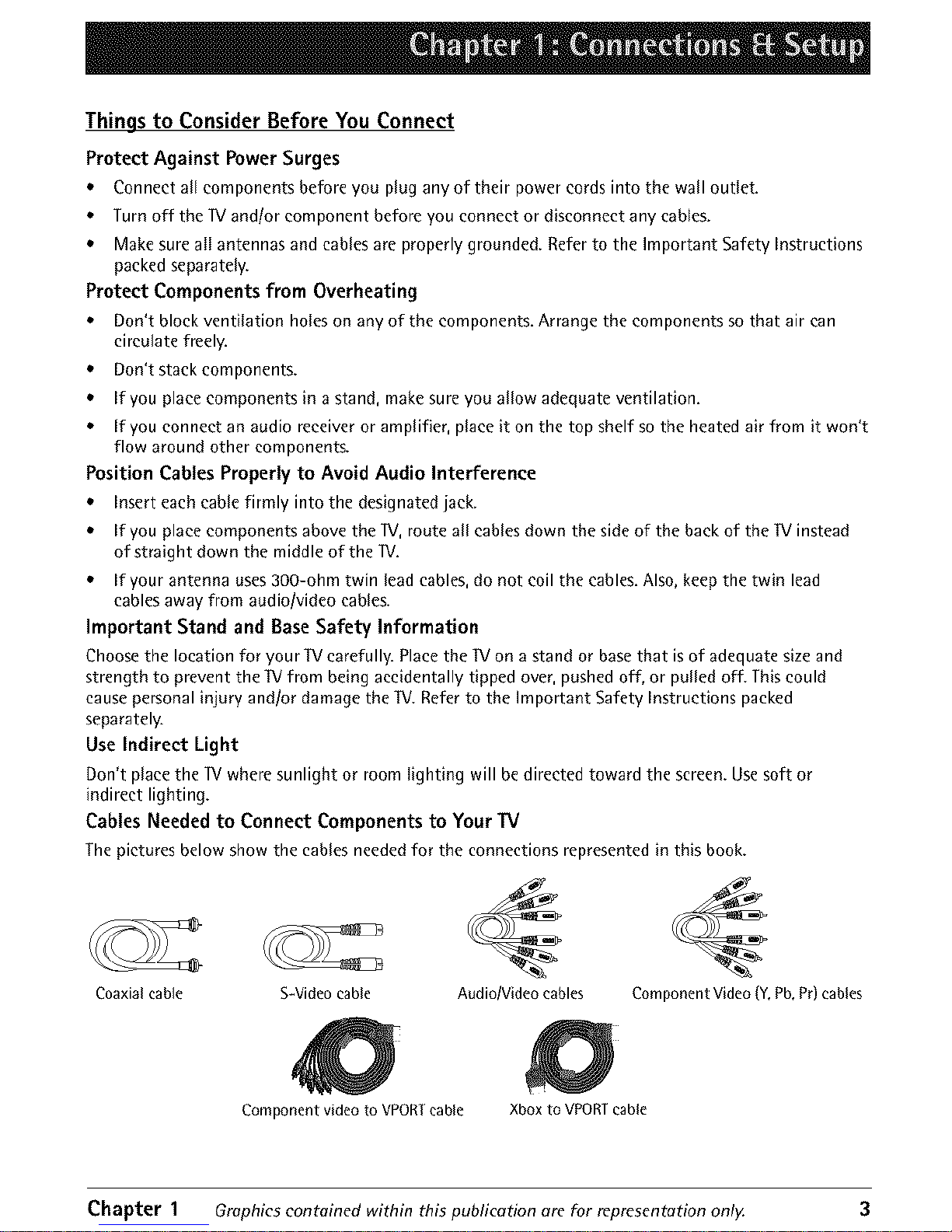
Cables Needed to Connect Components to Your IV
The pictures below show the cables needed for the connections represented in this book.
Coaxial cable S-Video cable Audio/Video cables
Component Video (Y,Pb,Pr)cables
Component video to VPORT cable Xbox to VPORT cable
Chapter 1 Graphics contained within this publication are for representation only. 3
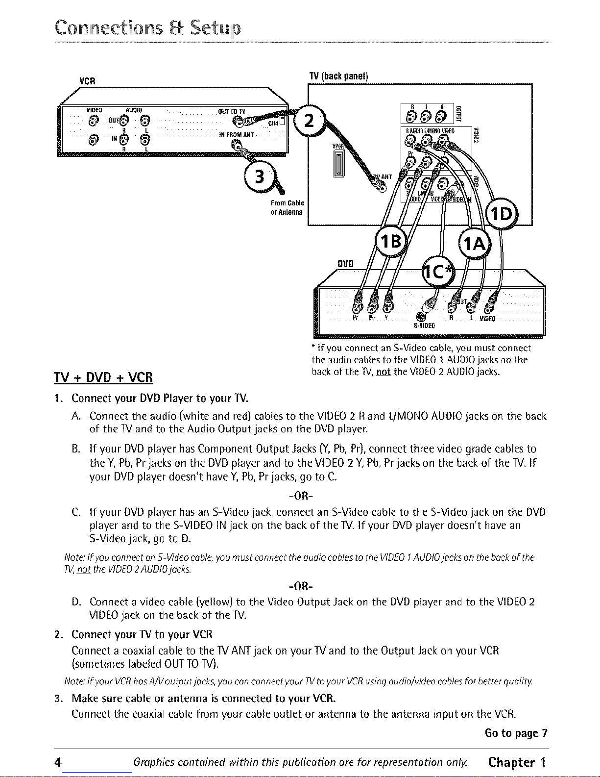
Co n nectio ns Setuo
TV(backpanel)
FromCable
or Antenna
TV + DVD + VCR
* If you connect an S-Video cable, you must connect
the audio cables to the VID[O I AUDIO jacks on the
back of the TV, not the VIDEO 2 AUDIO jacks.
I. Connect your DVDPlayerto your TV.
A. Connect the audio (white and red) cablesto the VIDEO2 Rand L/MONOAUDIOjacks on the back
of the IV and to the Audio Output jacks on the DVDplayer.
B. ff your DVD player has Component Output Jacks (Y, Pb, Pr), connect three video grade cables to
the Y, Pb, Prjacks on the DVD player and to the VIDEO 2 Y, Pb, Pr jacks on the back of the IV. If
your DVD player doesn't have Y, Pb, Pr jacks, go to C.
-OR-
C. If your DVD player has an S-Video jack, connect an S-Video cable to the S-Video jack on the DVD
player and to the S-VIDEO IN jack on the back of the IV. If your DVD player doesn't have an
S-Video jack, go to D.
Note:If you connect anS-Videocable,you must connect tile audio cablesto the VIDEO1AUDiOjacks on tile beckof the
W,not theVIDEO2AUDIOjaoks.
-OR-
D, Connect a video cable (yellow) to the Video Output Jack on the DVD player and to the VIDEO 2
VIDEO jack on the back of the IV.
2. Connect your TV to your VCR
Connect acoaxial cableto the 1VANTjack on your IV and to the Output Jackon your VCR
(sometimeslabeledOUTTOIV).
Nore:Ifyour VCRhasA/V outputjacks, youcon connect yourW to your VCRusingaudio/videocablesfor better quolitg
3. Make sure cable or antenna is connected to your VCR.
Connect the coaxial cable from your cable outlet or antenna to the antenna input on the VCR.
Go to page 7
4 Graphics contained within this publication are for representation onlg Chapter 1
CoHHeetioHS Setup
Xbox
DVD
TV (back panet)
or _lenna
Component video to
VPORT cable (not
supplied)
Xbox to VPORTcable
(not supplied)
Using the VPORT Jack
The VPORTjack lets you connect an Xbox TM video game system to the lV using an
Xbox to VPORT cable (not provided). Go to page 29 to purchase the Xbox to VPORT
cable. You can also connect a component, such as a DVD player, that has
component video jacks (Y, Pb, Pr) using a Component video to VPORT cable (not
provided). When using the Component video to VPORT cable, make sure to connect
the left and right audio cables to the component in order for the lV to receive
sound.
Note:TheVPORTjackconnot I)eusedfor geme consolesother tflontileXboxvideogorne
system.
I. Connect your TV to a DVD player
Use a Component video to VPORT cable (not provided) to connect your IV to
another component, such as a DVD player, that has Y, Pb, Pr jacks.
Connect the Component video to VPORT cable to the VPORTjack on the back
of the W.
Connect the other ends of the Component video to VPORT cable to the
Y, Pb, Pr and the Audio Output Jacks on the back of the DVD.
-OR-
2. Connect your TV to an Xbox video game system
Connect the end of an Xbox to VPORT cable (not provided) labeled Wto the
VPORTjack on the back of the TV and the other end to the corresponding jack
on the back of the Xbox video game system.
Note:If you hovean audio receiver,youm[ght be ableto connect a digital oudio cableto the
digitel o;;diojeck thet's on theVPORTcoble.
Go to page 7
"Xbox is a trademark of Microsoft Corporation in the United States andlor other
countries."
Chapter 1 Grophics eontoined within this publicotion are for representation only. 5
Co n nectio nsa Setup
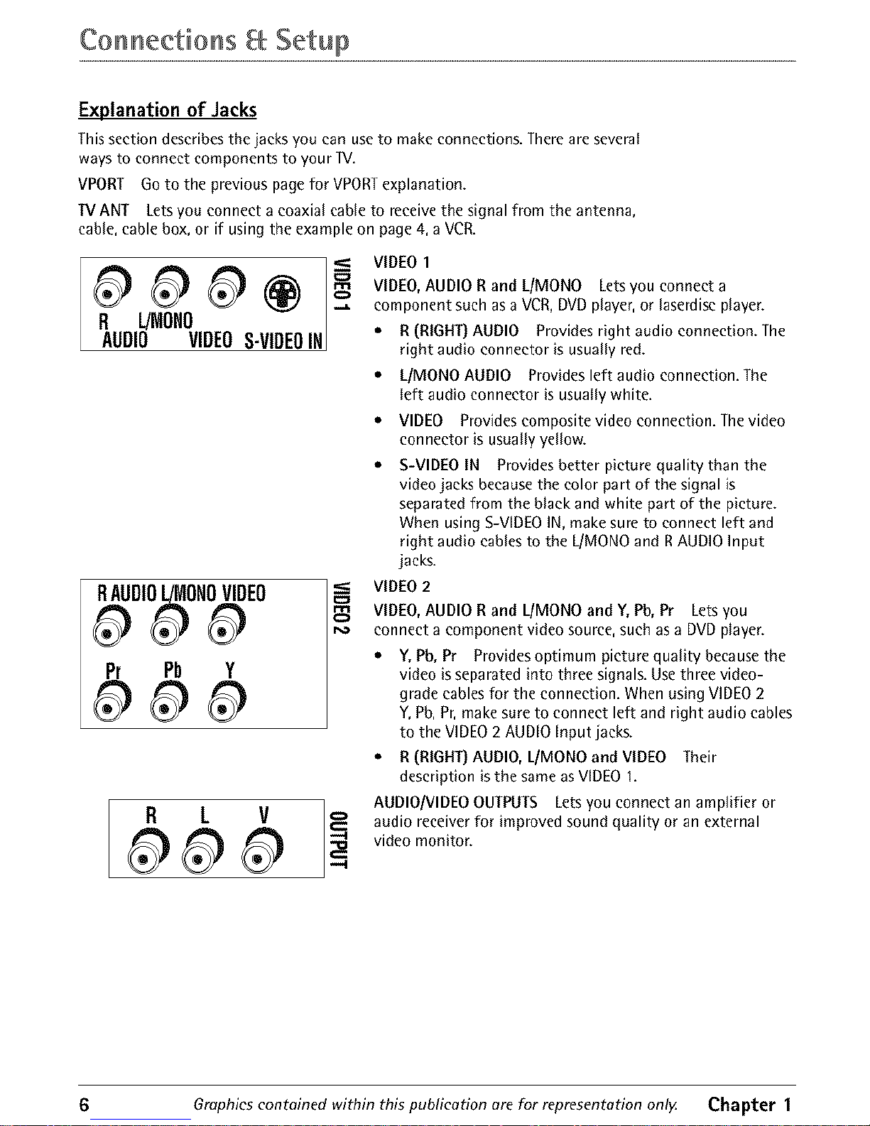
Explanation of Jacks
Thissection describesthe jacksyou can useto make connections. Thereare several
ways to connect components to your W.
VPORT Goto the previouspagefor VPORTexplanation.
13/ANT Letsyou connect a coaxial cable to receivethe signal from the antenna,
cable,cable box, or if using the example on page 4,a VCR.
R L/MONO
AUDIO VIDEOS-VIDEOIN
.,,a.
RAUDIOL/MONOVIDEO
Pr Pb Y
VIDEO 1
VIDEO, AUDIO R and LIMONO Lets you connect a
component such as a VCR, DVD player, or laserdise player.
• R (RIGHT} AUDIO Provides right audio connection. The
right audio connector is usually red.
• L/MONO AUDIO Provides left audio connection. The
left audio connector is usually white.
• VIDEO Provides composite video connection. The video
connector is usually yellow.
S-VIDEO IN Provides better picture quality than the
video jacks because the color part of the signal is
separated from the black and white part of the picture.
When using S-VIDEO IN, make sure to connect left and
right audio cables to the L/MONO and R AUDIO Input
jacks.
VIDEO 2
VIDEO,AUDIOR and LIMONO and Y,Pb, Pr Letsyou
connect a component video source,such as a DVDplayer.
• Y, Pb, Pr Provides optimum picture quality because the
video is separated into three signals. Use three video-
grade cables for the connection. When using VIDEO 2
Y,Pb, Pr, make sure to connect left and right audio cables
to the VIDEO 2 AUDIO Input jacks.
• R (RIGHT} AUDIO, L/MONO and VIDEO Their
description is the same as VIDEO I.
AUDIO/VIDEO OUTPUTS Lets you connect an amplifier or
audio receiver for improved sound quality or an external
video monitor.
6 Graphics contained within this publication are for representation onlg Chapter 1
CoHHeetioHS Setup
AUDIO I
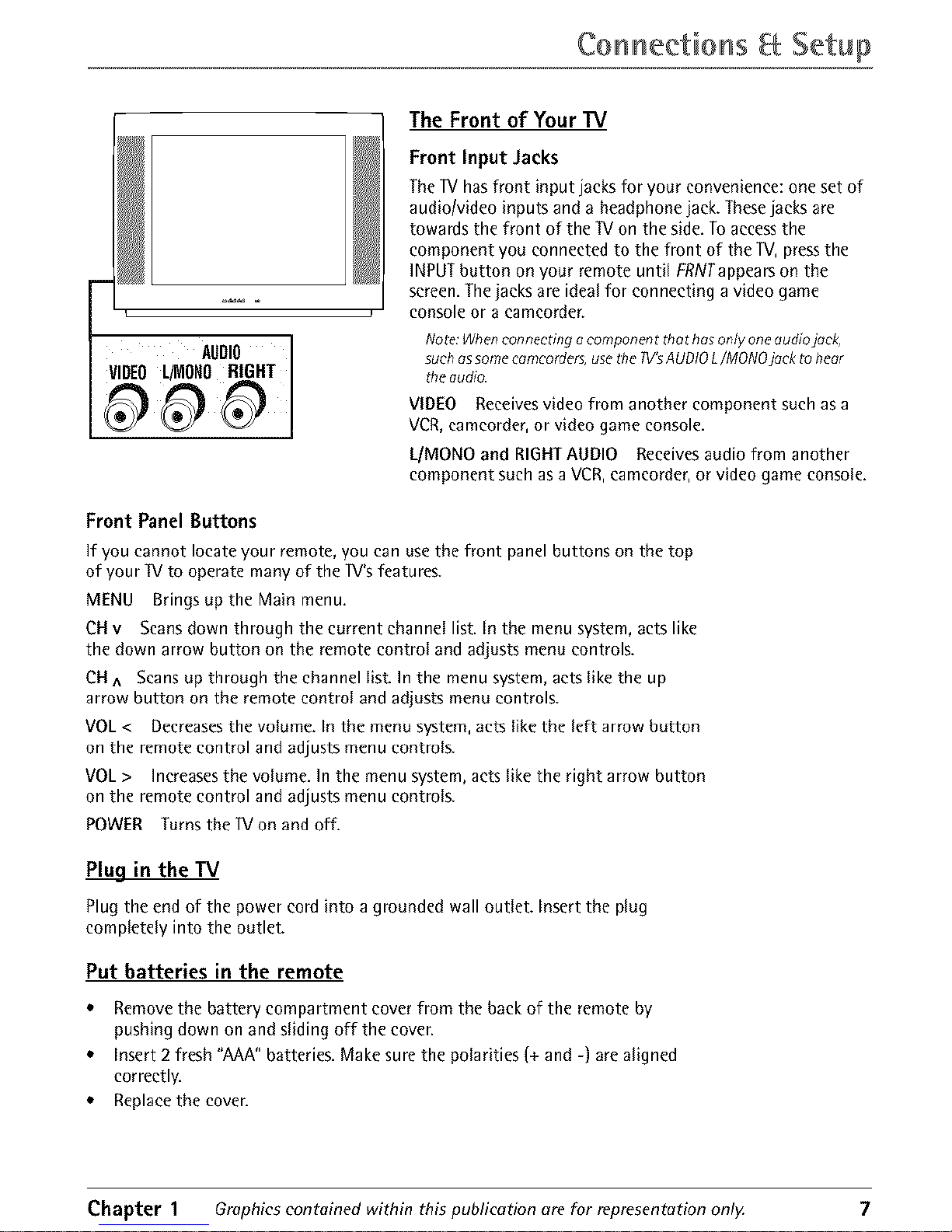
The Front of Your TV
Front Input Jacks
The1Vhasfront input jacks for your convenience: one set of
audio/video inputs and a headphonejack. Thesejacks are
towards the front of the W on the side.Toaccessthe
component you connected to the front of the IV, pressthe
INPUTbutton on your remote until FRNTappearson the
screen.Thejacks areideal for connecting a video game
console or a eameorder.
Note:Whenconnectingo component thet hasonly oneaudiojock,
suchassomecomcorders,usetile TV'sAUDIOL/MONOjock to heor
tile oudio.
VIDEO Receivesvideo from another component such asa
VCR,camcorder,or video game console.
I_/MONOand RIGHTAUDIO Receivesaudio from another
component such as a VCR,eameorder,or video game console,
Front Panel Buttons
If you cannot locateyour remote,you can usethe front panelbuttons on the top
of your TVto operate many of the 1V'sfeatures.
MENU Brings up the Main menu.
CH v Scans down through the current channel list. In the menu system, acts like
the down arrow button on the remote control and adjusts menu controls.
CH ^ Scans up through the channel list. In the menu system, acts like the up
arrow button on the remote control and adjusts menu controls.
VOL < Decreases the volume. In the menu system, acts like the left arrow button
on the remote control and adjusts menu controls.
VOL > Increases the volume. In the menu system, acts like the right arrow button
on the remote control and adjusts menu controls.
POWER Turns the 1Von and off.
Plug in the TV
Plug the end of the power cord into a grounded wall outlet. Insert the plug
completely into the outlet.
Put batteries in the remote
• Remove the battery compartment cover from the back of the remote by
pushing down on and sliding off the coven
• Insert 2 fresh "AAA" batteries. Make sure the polarities (+ and -) are aligned
correctly.
• Replace the coven
Chapter 1 Graphics contained within this publication are for representation only. 7
Co n nectio ns Setup
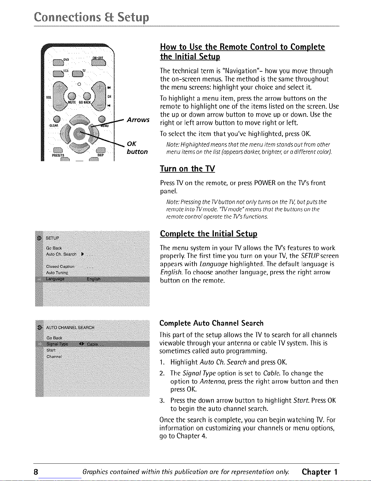
_._ Arrows
OK
button
How to Use the Remote Control to Complete
the Initial Setup
The technical term is "Navigation"- how you move through
the on-screen menus. The method is the same throughout
the menu screens: highlight your choice and select it.
To highlight a menu item, press the arrow buttons on the
remote to highlight one of the items listed on the screen. Use
the up or down arrow button to move up or down. Use the
right or left arrow button to move right or left.
To select the item that you've highlighted, press OK.
Note:Highlighted meansthat themenu itemstandsout from other
menu itemson the/;st (appearsdarker,brighter,or odifferent color]
Turn on the TV
Press]V on the remote, or pressPOWERon the ]V's front
panel.
Note:Pressingt#e Wbutton not only t_rns on theW_butputs the
remot_into Wmode. "Wmode"meansthat the buttons on the
remot_control operatethe TV'sfunctions
Complete the Initial Setup
The menu system in your ]V allows the IV's features to work
properly. The first time you turn on your lV, the SETUPscreen
appears with Language highlighted. The default language is
English. To choose another language, press the right arrow
button on the remote.
Complete Auto Channel Search
This part of the setup allows the lV to search for all channels
viewable through your antenna or cable IV system. This is
sometimes called auto programming.
1. Highlight Auto Ch. Search and press OK.
2. The Signal Type option is set to Cable To change the
option to Antenna, press the right arrow button and then
pressOK.
3. Press the down arrow button to highlight StarL PressOK
to begin the auto channel search.
Once the search is complete, you can begin watching ]V. For
information on customizing your channels or menu options,
go to Chapter 4.
8 Graphics contained within this publication are for representation onlg Chapter 1
 Loading...