

rca.com
User’s Guide
Changing Entertainment. Again.
Model 27F634T is pictured here.
Find Inside:
• Connecting .............. page 4
• Remote Control ...... page 9
• KidPass ..................... page 22
• Favorite Channel .... page 31
• Troubleshooting ..... page 37
Important Information
CAUTION
RISK OF ELECTRIC SHOCK
DO NOT OPEN
Caution: To reduce the risk of electric shock, do not remove cover (or back). No user serviceable parts inside. Refer
servicing to qualified service personnel.
This symbol indicates “dangerous voltage“ inside
the product that presents a risk of electric shock or
personal injury.
WARNING
To reduce the risk of fire or electric
shock, do not expose this product to
rain or moisture.
The apparatus shall not be exposed
to dripping or splashing and no
objects filled with liquids, such as
vases, should be placed on the
apparatus.
This symbol indicates that this product incorporates double insulation
between hazardous mains voltage and user accessible parts. When servicing
use only identical replacement parts.
This symbol indicates important instructions
accompanying the product.
Refer to the identification/rating label located on the back panel of your product for
its proper operating voltage.
FCC Regulations state that unauthorized changes or modifications to this equipment
may void the user’s authority to operate it.
Caution: To prevent electric shock, match wide blade of plug to wide slot, fully insert.
Caution: Using video games or any external accessory with fixed images for
extended periods of time can cause them to be permanently imprinted on the
picture tube (or projection TV picture tubes). ALSO, some network/program logos,
phone numbers, black borders (sides, top and bottom), etc. may cause similar
damage. This damage is not covered by your warranty.
Cable TV Installer: This reminder is provided to call your attention to Article 820-40
of the National Electrical Code (Section 54 of the Canadian Electrical Code, Part 1)
which provides guidelines for proper grounding and, in particular, specifies that the
cable ground shall be connected to the grounding system of the building as close to
the point of cable entry as practical.
Important Stand and Base Safety Information
Choose the location for your TV carefully. Place the TV on a stand or base that is of
adequate size and strength to prevent the TV from being accidentally tipped over,
pushed off, or pulled off. This could cause personal injury and/or damage the TV.
Refer to the Important Safety Instructions on page 1.
Product Registration
Please fill out the product registration card (packed separately) and return it immediately. For US customers: Your RCA Consumer
Electronics product may also be registered at www.rca.com/productregistration. Registering this product allows us to contact you
if needed.
Product Information
Keep your sales receipt to obtain warranty parts and service and for proof of purchase. Attach it here and record the serial and
model numbers in case you need them. These numbers are located on the product.
Model No. _________________ Serial No. _____________________Purchase Date: ________________________
Dealer/Address/Phone: __________________________________________________________________________
Important Information
IMPORTANT SAFETY INSTRUCTIONS
Read before operating equipment
1.
Read these instructions.
2. Keep these instructions.
3. Heed all warnings.
4. Follow all instructions.
5. Do not use this apparatus near water.
6. Clean only with a dry cloth.
7. Do not block any of the ventilation openings. Install in accordance
with the manufacturer’s instructions.
8. Do not install near any heat sources such as radiators, heat
registers, stoves, or other apparatus (including amplifiers) that
produce heat.
9. Do not defeat the safety purpose of the polarized or grounding
type plug. A polarized plug has two blades with one wider than the
other. A grounding type plug has two blades and a third grounding
prong. The wide blade or third prong are provided for your safety.
When the provided plug does not fit into your outlet, consult an
electrician for replacement of the obsolete outlet.
10. Protect the power cord from being walked on or pinched,
particularly at plugs, convenience receptacles, and the point where
they exit from the apparatus.
11. Only use attachments/accessories specified by the
12. Use only with a cart, stand, tripod, bracket, or table specified by
13. Unplug this apparatus during lightning storms or when unused for
14. Refer all servicing to qualified service personnel. Servicing is
15. This product may contain lead and mercury. Disposal of these
16. Damage Requiring Service - The appliance should be serviced by
Note to the Cable TV system installer: This reminder is provided to call the Cable TV system installer’s attention to Article 820-40 of the NEC
(Section 54 of the Canadian Electrical Code, Part 1) that provides guidelines for proper grounding and, in particular, specifies that the cable ground
shall be connected to the grounding system of the building, as close to the point of cable entry as practical.
manufacturer.
the manufacturer or sold with the apparatus. When a cart is used,
use caution when moving the cart/apparatus combination to avoid
injury from tip-over.
long periods of time.
required when the apparatus has been damaged in any way, such
as if the power-supply cord or plug is damaged, liquid has been
spilled or objects have fallen into the apparatus, or if the apparatus
has been exposed to rain or moisture, does not operate normally,
or has been dropped.
materials may be regulated due to environmental considerations.
For disposal or recycling information, please contact your local
authorities or the Electronic Industries Alliance (www.eiae.org).
qualified service personnel when:
A. The power supply cord or the plug has been damaged;
B. Objects have fallen or liquid has been spilled into the appliance;
C. The appliance has been exposed to rain;
D. The appliance does not appear to operate normally or exhibits a
marked change in performance;
E. The appliance has been dropped or the enclosure damaged.
17. Tilt/Stability - All televisions must comply with recommended
international global safety standards for tilt and stability proper ties
of its cabinet design.
• Do not compromise these design standards by applying
excessive pull force to the front, or top, of the cabinet, which could
ultimately overturn the product.
• Also, do not endanger yourself, or children, by placing electronic
equipment/toys on the top of the cabinet. Such items could
unsuspectingly fall from the top of the set and cause product
damage and/or personal injury.
18. Power Lines - An outdoor antenna should be located away from
power lines.
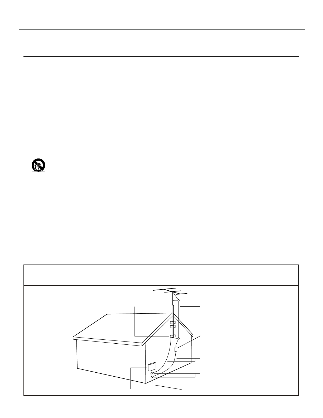
19. Outdoor Antenna Grounding - If an outside antenna is connected
to the receiver, be sure the antenna system is grounded so as to
provide some protection against voltage surges and built up static
charges.
Section 810 of the National Electrical Code, ANSI/NFPA No. 70-
1984, provides information with respect to proper grounding of the
mast and supporting structure, grounding of the lead-in wire to an
antenna discharge unit, size of grounding connectors, location of
antenna-discharge unit, connection to grounding electrodes, and
requirements for the grounding electrode. See Figure below.
20. Object and Liquid Entry - Care should be taken so that objects
do not fall and liquids are not spilled into the enclosure through
openings.
21. Battery usage CAUTION - To prevent battery leakage that may
result in bodily injury, property damage, or damage to the unit:
• Install all batteries correctly, with + and - aligned as marked on
the unit.
• Do not mix batteries (old and new or carbon and alkaline, etc.).
• Remove batteries when the unit is not used for a long time.
22. Apparatus shall not be exposed to dripping or splashing and no
objects filled with liquids, such as vases, shall be placed on the
apparatus.
Example of Antenna Grounding
as per NEC - National Electrical Code
ELECTRIC SERVICE EQUIPMENT
GROUND CLAMP
ANTENNA LEAD IN WIRE
ANTENNA DISCHARGE UNIT
(NEC SECTION 810-20)
GROUNDING CONDUCTORS
(NEC SECTION 810-21)
GROUND CLAMPS
POWER SERVICE GROUNDING ELECTRODE SYSTEM
(NEC ART 250, PART H)

Table of Contents
Chapter 1: Connections & Setup
Things to Consider Before You Connect ......................................................................... 4
Protect Against Power Surges .................................................................................... 4
Protect Devices from Overheating ............................................................................4
Position Cables Properly to Avoid Audio Interference ............................................. 4
Use Indirect Light ........................................................................................................ 4
Getting a Signal ................................................................................................................5
Using the Antenna Input ...........................................................................................5
Using the Cable Input ................................................................................................. 5
Choose Your Connection ..................................................................................................
Y Pb Pr Connection ..................................................................................................... 6
S-Video Connect
Plug in the TV .................................................................................................................... 9
Put batteries in the Remote ............................................................................................. 9
How to Use the Remote Control to Complete the Initial Setup ....................................
Turn on the TV ...................................................................................................................
Complete the Initial Setup .............................................................................................10
Choose the Menu Language .................................................................................... 10
Tuning to a Channel ................................................................................................. 10
Using the INPUT Button .................................................................................................. 12
Explanation of Jacks ....................................................................................................... 13
The Front of Your TV ......................................................................................................
ion ..........................................................................................................8
14
6
9
9
Chapter 2: Using the TV Features
Front Buttons ............................................................................................................15
Side View Buttons ..................................................................................................... 15
Channel Banner ............................................................................................................... 16
Parental Controls and V-Chip .........................................................................................
How V-Chip Works .................................................................................................... 17
Activate Parental Control ...............................................................................................
Resetting the Password ............................................................................................17
To Set V-Chip TV Programming Limits: .................................................................... 18
The V-Chip Rating Screen ......................................................................................... 18
Blocking Age-Based Ratings ....................................................................................18
Blocking Specific Content Themes ........................................................................... 19
Blocking USA V-Chip Movie Ratings ........................................................................ 20
Blocking Canadian V-Chip Movie Ratings ............................................................... 21
V-Chip Exempt Program Block ................................................................................. 21
Activate KidPass ........................................................................................................ 22
Block Channel ........................................................................................................... 22
Front Panel Lock ....................................................................................................... 23
Change Your Password ............................................................................................. 23
17
17
2

Table of Contents
Chapter 3: Using the TV’s Menu System
Sound Menu .................................................................................................................... 24
Picture Menu ...................................................................................................................
Setup Menu ..................................................................................................................... 27
Parental Control Menu ..................................................................................................
Time Menu .......................................................................................................................33
Notepad Menu ................................................................................................................ 34
Chapter 4: Other Information
USA V-Chip Rating System ............................................................................................. 35
Canadian English V-Chip Rating System .......................................................................
Canadian French V-Chip Rating System ........................................................................
Troubleshooting ..............................................................................................................
Limited Warranty ............................................................................................................
Care and Cleaning ...........................................................................................................
FCC Information .............................................................................................................. 42
26
32
35
36
37
39
41
3

Chapter 1: Connections & Setup
Things to Consider Before You Connect
Protect Against Power Surges
• Connect all devices before you plug any of their power cords into the wall outlet.
• Turn off the TV and/or device before you connect or disconnect any cables.
• Using a surge protector can help prevent damage to your TV from electrical power surges. In
case of lightning, unplug your TV.
• Make sure all antennas and cables are properly grounded. Refer to the Important Safety
Instructions packed separately.
Protect Devices from Overheating
• Don’t block ventilation holes on any of the devices. Arrange the devices so that air can
circulate freely.
• Don’t stack devices.
• If you place devices in a stand, make sure you allow adequate ventilation.
• If you connect an audio receiver or amplifier, place it on the top shelf so the heated air from
it won’t flow around other devices. Position Cables Properly to Avoid Audio Interference
Position Cables Properly to Avoid Audio Interference
• Insert each cable firmly into the designated jack.
• If you place devices above the TV, route all cables down the side of the back of the TV
instead of straight down the middle of the TV.
• If your antenna uses 300-ohm twin lead cables, do not coil the cables. Also, keep the twin
lead cables away from audio/video cables.
Use Indirect Light
Don’t place the TV where sunlight or room lighting will be directed toward the screen. Use soft
or indirect lighting.
4
(DIGITAL
ANTENNA)
DTV ANT
(ANTENNA
INPUT)
(DIGITAL
ANTENNA)
DTV ANT
TV ANT
Connections & Setup
Getting a Signal
Your TV is capable of receiving both off-air (via an antenna) digital signals and cable/analog
signals. The off-air digital signal can be used by both high definition and standard definition TVs,
like this set. The off-air digital signal picture that you receive will be superior to an analog signal.
You may experience a delay of several seconds before digital off-air pictures appear, both when
you first turn on the digital signals and when you change channels. This is normal.
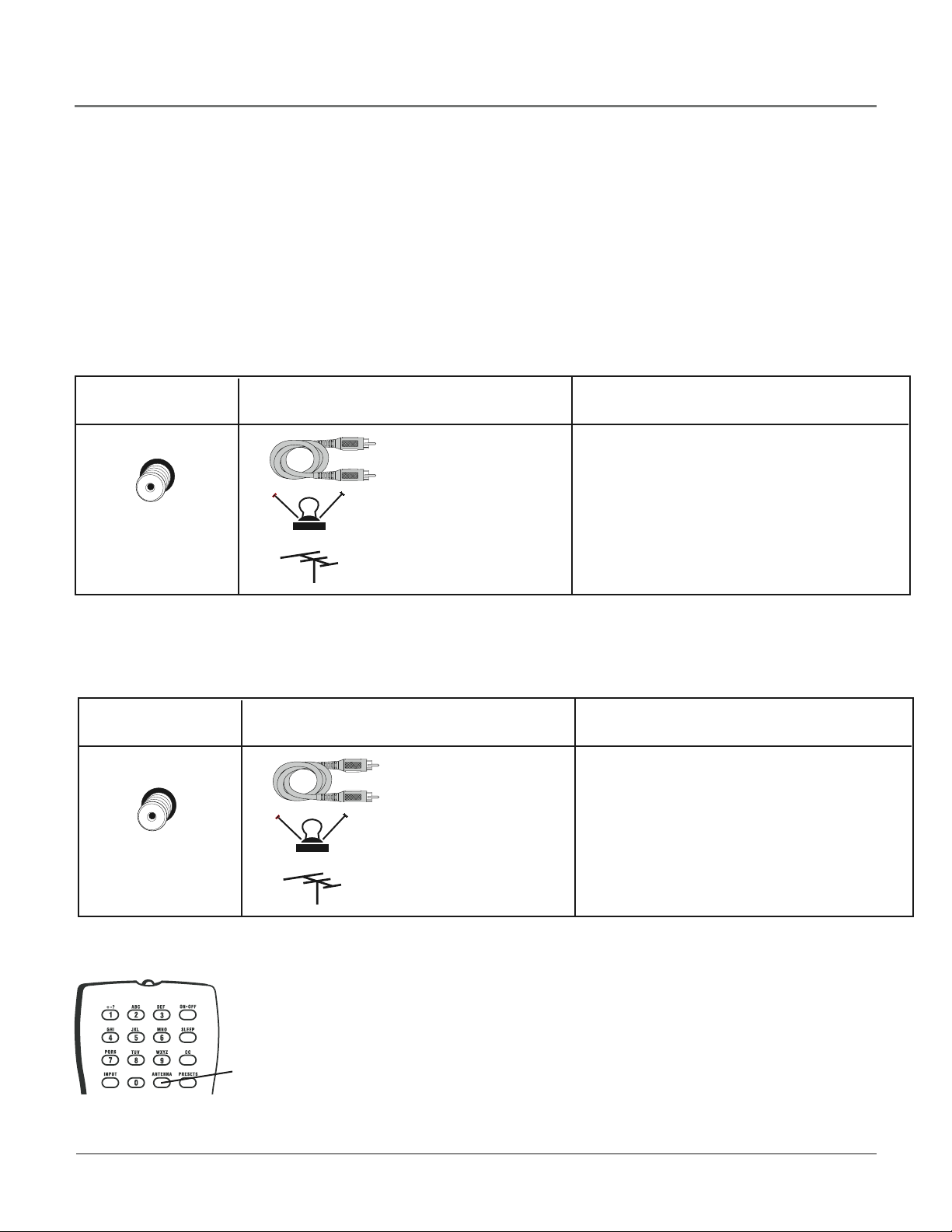
Using the Antenna Input
Connect a coaxial cable from an off-air antenna to the DTV ANT jack (top) to receive off-air digital channels.
Jack Used What You Need What you need to know...
Coaxial cable
Digital (off-air) signals can only enter this
TV through the top RF jack.
If you need help deciding what type of
Indoor OR
antenna to use, go to antennaweb.org.
By entering where you live, this mapping
Top INPUT
Outdoor Antenna
program tells you what local analog and
digital stations are available to you.
Using the Cable Input
Cable/analog signals can only enter this TV through the bottom RF jack.
Jack Used What You Need What you need to know...
Connect a coaxial cable from cable jack
to the TV ANT jack (bottom) to receive
cable channels.
If you wish, you can use this input to
connect a second antenna connection.
Bottom INPUT
Coaxial cable
Indoor OR
Outdoor Antenna
When using both of these jacks, use the ANTENNA button on the
remote to toggle between the off-air digital and cable/analog signals.
ANTENNA
button
Chapter 1 5
Graphics contained within this publication are for representation only.
(ANTENNA
INPUT)
VIDEO OUT
(OUTPUT)
(INPUT)
(DIGITAL
ANTENNA)
DTV ANT
TV AN
T
(
ANTENNA
INPUT
)
V
COMPONENT VIDEO
Y Pb Pr
VIDEO
INPUT
L R
AUDIO
VIDEO
OUTPUT
S-VIDEO
OUT
S-VIDEO
IN
L R
AUDIO
L R
AUDIO
VIDEO IN
(INPUT)
Connections & Setup
Choose Your Connection
There are several ways to connect your TV, depending on the devices you want to connect and
the quality of the signal you want to achieve. An excellent connection is achieved using
Y Pb Pr jacks. Connections will vary according to the types of outputs jacks each external device
can accommodate (i.e., DVD players usually have Y Pb Pr outputs but video game consoles do
not).
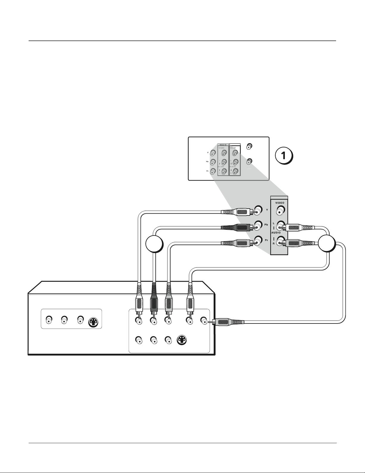
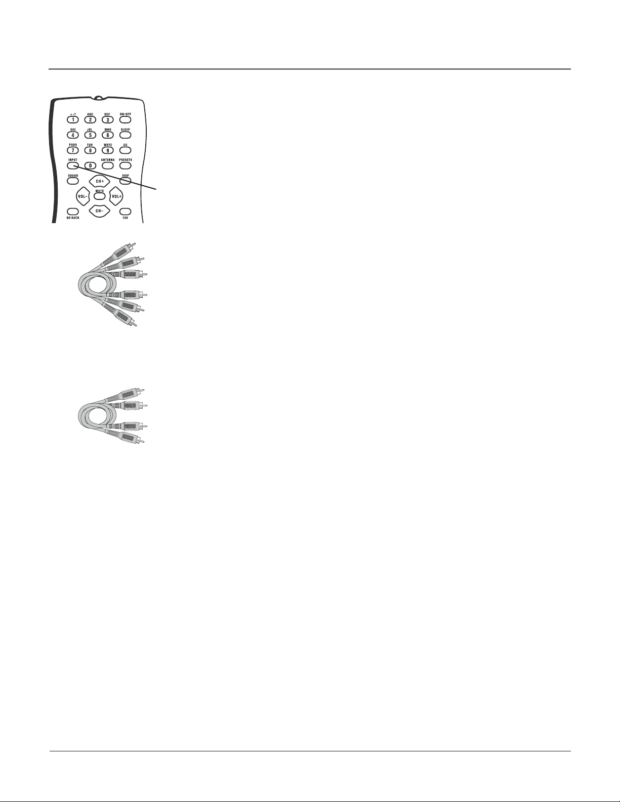
Y Pb Pr Connection
Back of TV
Go to page 5 for
instructions on
getting a signal.
DVD Player
2
3
6
INPUT
button
Connections & Setup
Viewing the Picture from the Connected Device
The device in this example, a DVD player, is connected to the TV’s Y Pb Pr and
VIDEO IN audio jacks. To view the DVD player:
1. Turn on the TV and the DVD player.
2. Use the INPUT button on the remote control to toggle through the Video Input
Channels until you see CVID displayed in the channel banner.
Connecting the Device
This connection allows you to connect a device that has Y Pb Pr jacks, for example, a
DVD player. If the device you are connecting also has S-Video or composite video, we
recommend you use the component video input for better quality.
The illustration on the previous page shows how to connect a DVD to your TV using
component (Y Pb Pr) and audio cables.
Using the example of a DVD player:
Component Video
cables (Y Pb Pr) are
color coded- Green,
Blue and Red
Audio cables are color
coded- Red= right audio;
white= left audio
1. Connect your cable and/or off-air antenna as described on page 5.
2. Connect your Y Pb Pr component video cables.
Connect three video grade cables to the Y Pb Pr jacks on the back of the TV and
to the Y Pb Pr outputs on the DVD player. Y Pb Pr cables are colored green, blue
and red. Just match the colors on the cables and Y Pb Pr jacks.
3. Connect your audio cables.
Connect the audio (white and red) cables to the VIDEO IN R and L Audio jacks on
the back of the TV and to the audio output jacks on the DVD player.
Just match
the colors.
Important - Y Pb Pr cables can only be used with the VIDEO IN audio jacks located
on the back of the TV. You cannot use any other input jacks on this TV for this
connection.
Chapter 1 7
L AUDIO R
S-VIDEO
H-PHONE
VIDEO
VIDEO
INPUT
L R
AUDIO
VIDEO
OUTPUT
S-VIDEO
OUT
S-VIDEO
IN
L R
AUDIO
L R
AUDIO
Connections & Setup
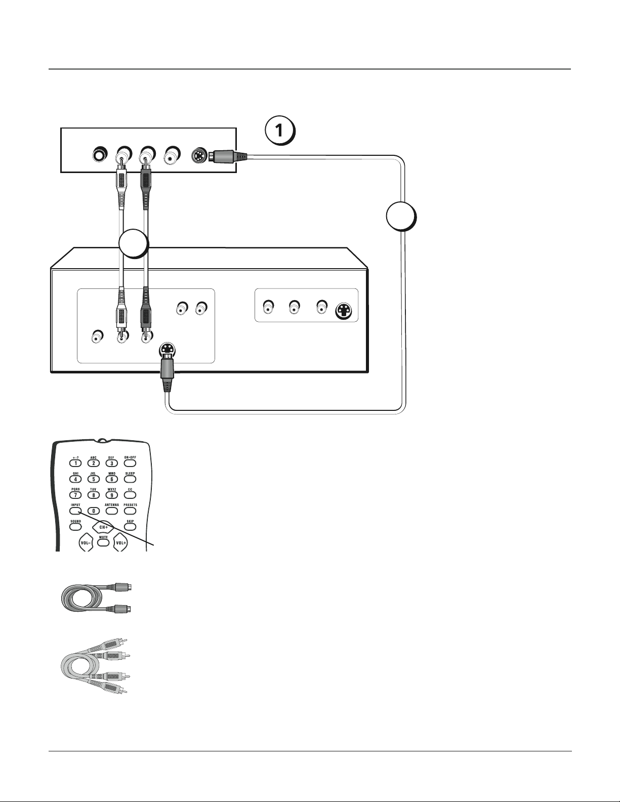
S-Video Connection
Side of TV
3
Go to page 5 for
instructions on
getting a signal.
2
Video Game Console
S-Video cable
Audio cables
Viewing the Picture from the Connected Device
The device in this example, a video game console, is connected to the TV’s S-Video and
audio jacks located on the side of the TV. To view the video game console:
1. Turn on the TV and the video game console.
2. Use the INPUT button on the remote control to toggle through the Video Input
INPUT
button
Channels until you see SVID displayed in the channel banner.
Connecting the Device
This connection allows you to connect a device, such as a video game console, that has an
S-Video jack. Refer to the illustration below which uses S-Video and audio cables.
Using the example of a video game console:
1. Connect your cable and/or off-air antenna as described on page 5.
2. Connect your S-Video cables.
S-Video cables fit into a special shaped jack which will be labeled S-Video. Connect the
S-Video cable to the jack on the side of the TV and the jack on the video game console.
3. Connect your audio cables.
Connect the audio (white and red) cables to the R and L Audio jacks on the side of the
TV and to the audio output jacks on the video game console. Just match the colors.
8
Connections & Setup
Plug in the TV
Plug the end of the power cord into a grounded wall outlet. Insert the plug completely into the
outlet.
Put batteries in the Remote
• Remove the battery compartment cover from the back of the remote by pushing down
and sliding off the cover.
• Insert 2 fresh “AA” batteries. Make sure the polarities (+ and -) are aligned correctly to the
diagram inside the battery compartment.
• Replace the cover.
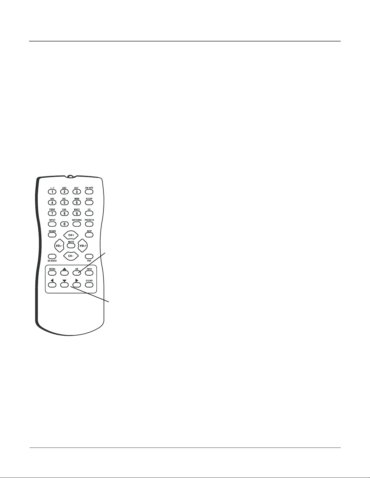
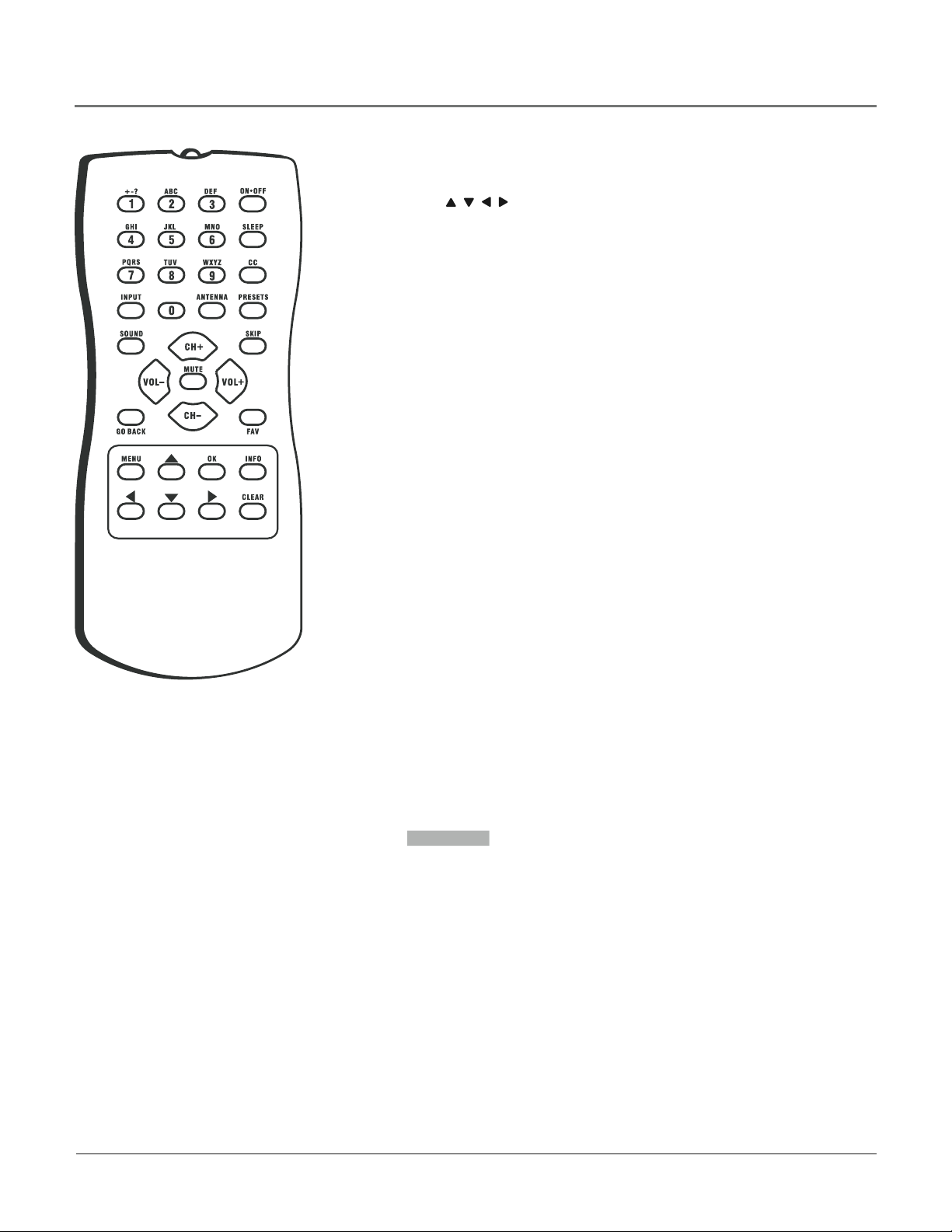
How to Use the Remote Control to
Complete the Initial Setup
The technical term is “Navigation” - how you move through the
on-screen menus. The method is the same throughout the menu screens:
highlight your choice and select it.
OK button
Arrow
buttons
To highlight a menu item, press the arrow buttons on the remote to
highlight one of the items listed on the screen. Use the up or down
arrow button to move up or down. Use the right or left arrow button to
move right or left.
To select the item that you’ve highlighted, press OK.
Note: Highlighted means that the menu item stands out from
other menu items on the list (appears darker, brighter or a
different color).
Turn on the TV
Press ON•OFF on the remote, or press POWER on the TV’s front panel.
Chapter 1 9
Go Back
Auto Ch. Search ...
List & Labels ...
Closed Caption ...
Favorite CH ...
Language English...
Auto. format 4:3
SETUP
< >
Go Back
Signal Source Analog...
Analog Sig. Type Cable...
Start Running...
Channel 12
SETUP
< >
Go Back
Auto Ch. Search ...
List & Labels ...
Closed Caption ...
Favorite CH ...
Language English...
Auto. format 4:3
SETUP
< >
_12
012-1_ _
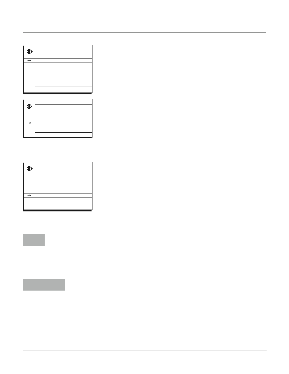
Connections & Setup
Complete the Initial Setup
The SETUP screen is the first screen you’ll see when you turn on the TV. (It is
located in the Main menu). This part of the SETUP allows the TV to search for
all channels viewable through your off-air digital antenna and your cable/analog
antenna connections. This is sometimes called auto programming.
1. In the SETUP menu, use the arrow buttons to select Auto Ch. Search. Then
press OK.
2. Press the right arrow button to scroll through the Signal Source (Digital,
Analog, Both).
3. With the Signal Source chosen, press the arrow down button to select Start
and press OK. AUTO CHANNEL SEARCH runs for several minutes as it finds
all the available channels.
4. Once the search is complete, you can begin watching TV. For information
on customizing your channels or menu options, go to Chapter 3.
Note: After you complete the Auto Channel Search you may see an
additional screen. “Time stored in the TV may be incorrect after a loss of
power. Please check the time in the Time menu” may appear, reminding
you that the time setting is incorrect. Go to page 33 for more information.
Cable channel
example entry
Digitalchannel
example entry
10
Choose the Menu Language
To set the language, use the arrow buttons to highlight Language. The default
language is English. To choose another language, press the right arrow button
on the remote.
Tuning to a Channel
Cable/analog station numbers display on your TV in a rectangle as you enter the numbers.
You can enter digits to access a channel. In the example below, you can enter 12 or 012 to
get the same channel. To enter a one-digit channel, such as channel 8, use two digits. For
example, enter 0 then 8. After entering the channel, press OK. The CLEAR button on the
remote clears all entries.
Digital off-air station numbers display in a larger rectangle that can contain up to six numbers.
Numbers to the left of the - (dash) are the main channel number; numbers to the right are the
subchannel numbers for stations that broadcast more than one signal. For example, if channel
12 is broadcasting subchannel signals, you would enter numbers that would access the other
signals. (example: 12-1, 12-2, 12-3). Press the right arrow to access the subchannel entry. Once
you’ve made all entries, press OK. The CLEAR button on the remote clears all entries.
Note: You may experience a delay of several seconds before digital off-air pictures
appear, both when you first turn on the digital signals and when you change channels.
This is normal.
Connections & Setup
SKIP 00:30
ANTENNA Toggles between the off-air digital channel source and the
cable/analog channel signal source. Refer to page 5 for a full description.
Arrow buttons (
to adjust the menu controls.
(0-9) Number buttons Enter channel numbers (refer to the previous page), time
settings (refer to page 33), labels (refer to page 28) and notepad messages (refer
to page 34).
CC Toggles closed captioning on and off when closed-caption menu option is
turned on.
CH + or CH - Scans up or down through all the available stations on either
your cable/analog or off-air digital connection. Press once to change the channel
up or down; press and hold to continuously change channels.
CLEAR Removes any menu or display from the screen and returns you to
normal TV viewing.
FAV (Favorite) Press to browse the channels in your
31 for more information.
GO BACK Returns you to the previous channel or menu.
INFO Brings up the channel banner. Press again to remove. Refer to page 16
for more information.
INPUT Toggles through the available Video Input Channels (VID1, CVID,
FRNT, SVID and current channel).
, , , ) Used to highlight different items in the TV menu and
Favorite List. Refer to page
MENU Brings up the MAIN MENU system.
MUTE Reduces the TV’s volume to its minimum level. Press again to restore
the volume.
OK When in the menu system, selects highlighted items.
ON•OFF Turns the TV on and off.
PRESETS Resets picture options to original factory settings.
SKIP Press once before changing channels; watch the screen for the
SKIP box (
will appear. Enter the new channel number. The TV will change to the new
channel and return to the original channel in 30 seconds. Press repeatedly to
add more time.
SLEEP Allows you to activate/deactivate the sleep timer by taking you to the
Sleep Timer menu. Refer to page 33.
SOUND Press to select one of the five sound settings when viewing
cable/analog antenna signals (Standard, Music, Speech, Theatre or Personal).
Refer to page 24 for more information.
VOL - or VOL + Decreases or increases the TV’s volume.
) to appear. Press the SKIP button again - 30 seconds
Chapter 1 11

Connections & Setup
Using the INPUT Button
Use the INPUT button to scroll through the available Video Input Channels to view
components you have connected to the TV.
1. Make sure the component you want to view is turned ON.
2. Press INPUT to tune to an available Video Input Channel and view the component.
3. To return to the previous channel, continue pressing INPUT.
12

(DIGITAL
ANTENNA)
DTV ANT
(ANTENNA
INPUT)
(DIGITAL
ANTENNA)
DTV ANT
TV ANT
(ANTENNA
INPUT)
VIDEO OUT
(OUTPUT)
VIDEO IN
(INPUT)
(DIGITAL
ANTENNA)
DTV ANT
TV ANT
(ANTENNA
INPUT)
VIDEO OUT
(OUTPUT)
VIDEO IN
(INPUT)
(DIGITAL
ANTENNA)
DTV ANT
TV ANT
Connections & Setup
Explanation of Jacks
This section describes the jacks you can use to make connections. There are several
combinations available to connect devices to your TV.
OFF-AIR DIGITAL INPUT Lets you connect a coaxial (RF) cable to receive off-air
local digital signals from your antenna. Refer to page 5 for more details.
ANALOG/CABLE INPUT Lets you connect a coaxial (RF) cable to cable service or
an external antenna. Refer to page 5 for more details.
Use the ANTENNA button to toggle between these RF inputs.
VIDEO IN Lets you connect devices which have Audio/Video (composite) outputs
such as VCRs, DVD players, satellite receivers, cable boxes, camcorders and video
game consoles. Connect the left and right audio jacks for sound.
• VIDEO Provides composite video connection. The video connector is usually
yellow.
• AUDIO-L Provides left audio connection. The left audio connector is usually
white.
• AUDIO-R Provides right audio connection. The right audio connector is usually
red.
To access the device when using these jacks, use the INPUT button on your remote
until VID1 appears.
Y, Pb, Pr Lets you connect devices which have component (Y Pb Pr) outputs such
as VCRs, DVD players, DVD-PVRs, DVD recorders, satellite receivers and cable boxes.
This connection provides optimum picture quality because the video is separated into
three signals. Use the VIDEO IN left and right audio jacks to connect for sound.
To access the device when using these jacks, use the INPUT button on your remote
until CVID appears.
Refer to page 6 for a detailed explanation of how to connect Y Pb Pr cables to your
TV.
Continues on next page...
Chapter 1 13

L AUDIO R
S-VIDEO
VIDEO
(ANTENNA
INPUT)
VIDEO OUT
(OUTPUT)
(DIGITAL
ANTENNA)
DTV ANT
TV ANT
Connections & Setup
VIDEO OUT Lets you connect your TV to external device inputs such as VCRs, Digital
recorders or secondary monitors. Audio/video (composite) cables are used for this connection.
Notes: These connections are not available through the VIDEO OUT: digital
off-air antenna connections (DTV jack) and the component inputs (Y, Pb, Pr).
What is available through the VIDEO OUT: Cable/analog antenna connections (TV
ANT), VIDEO IN and S-VIDEO.
The Front of Your TV
You can use the buttons and jacks on the front of your TV to operate many of the TV’s features.
FRONT (INPUT) These jacks are located on the side of the TV. Lets you connect
devices which have composite outputs such as VCRs, DVD players, satellite receivers,
cable boxes, video game consoles and camcorders.
• VIDEO Provides composite video connection. The video connector is usually
yellow.
• AUDIO-L Provides left audio connection. The left audio connector is usually
white.
• AUDIO-R Provides right audio connection. The right audio connector is usually
red.
To access the device when using these jacks, use the INPUT button on your remote
until FRNT appears.
- OR -
S-VIDEO Lets you connect external devices which have S-Video outputs such as
VCRs, DVD players, satellite receivers and cable boxes. Connect the left and right
audio jacks located on the side of the TV for sound. Refer to page 8 for a detailed
explanation of how to connect S-Video cables to your TV.
• AUDIO-L Provides left audio connection. The left audio connector is usually
white.
• AUDIO-R Provides right audio connection. The right audio connector is usually
red.
To access the device when using these jacks, use the INPUT button on your
remote until SVID appears.
14
Remember: You can use either the Video connection above (first choice) or the
S-video connection (second choice), but you cannot connect both at the same time.

Connections & Setup
Front Buttons
POWER Turns the TV on and off.
SENSOR Receives infra-red signals from the remote.
Side View Buttons
TV/VIDEO (INPUT) Chooses between TV programming and the available Video Input Channels. Acts like the
INPUT button on the remote.
MENU Brings up the MAIN MENU. In the menu system, clears the screen.
VOLUME -/+ Decreases/increases the volume. In the menu system, acts like the left/right arrow button on the
remote control and adjusts menu controls.
CHANNEL -/+ Scans up and down through the current channel list. In the menu system, acts like the down/up
arrow button on the remote control. Use to highlight items.
Chapter 1 15

SAP KidPass: 08:30 CC
STEREO Skip: 0:30 07:18am
11
CNN X
SAP KidPass: 08:30 CC
STEREO Skip: 0:30 07:18am
11
-2 X
DTV Program
DTV Program Description
Chapter 2: Using the TV Features
Channel Banner
There are several items that might appear on-screen when you press the INFO
Channel Banner menu for
analog/cable signal.
button on the remote. This display is called the Channel Banner. The following
list describes the items on the Channel Banner screen.
SAP Displayed when the current channel is broadcasting SAP (Second
Audio Program) information. Refer to page 25 for more information.
(lock) or (unlock) for Parental Control (Refer to page 17).
• The lock icon is displayed when all Parental Control settings are
active.
• The unlock icon is displayed when all Parental Control settings are
deactivated.
KidPass: 08:30 Corresponds to the KidPass function (refer to page 22).
Shows the amount of time left before the TV switches to standby.
CC Displayed when Closed Captioning is available on the current channel.
STEREO or (MONO) STEREO is displayed when the current channel is
broadcasting in stereo. MONO is displayed when the current channel is
broadcasting in mono.
Channel Banner menu for
off-air digital signal.
Skip: 0:30 Corresponds to the SKIP button. Shows the amount of time left
before the TV switches back to the previous channel. (Refer to page 11)
07:18 am Displays the current time.
The following Channel Banner display is available for cable/analog signals
but not for off-air digital signals:
11 CNN Displays the current channel and label assigned to the channel.
The following Channel Banner display is available for off-air digital signals but
not for cable/analog signals:
11-2 Displays the current channel but does not display the channel label
that you entered in the Setup/Lists and Labels screen.
Off-air digital signals can contain the channel name and a program
description. If available, look for that information to be displayed below the
current channel number.
X Displayed when you MUTE the sound.
16
Graphics contained within this publication are for representation only.

PARENTAL CONTROL
Go Back
Lock
Settings ...
Change Passwrd
Using the TV’s Features
Parental Controls and V-Chip
The choices in the USA V-CHIP menu involve software inside your TV (referred to as V-Chip) which allows you to
block TV programs and movies based on violence, sex or other content you may believe children should not view.
Once you block programs, you can unblock programs by entering a password.
By default, the software inside your TV is turned “off.” For instructions to turn on V-Chip, refer to Activate Parental
Control
How V-Chip Works
V-Chip reads the program’s age-based rating (TV-MA, TV-14, etc.) and content themes (Violence (V), Adult Language
(L), etc.). If you have blocked the rating and/or content themes that the program contains, you will receive the
message: This channel has not been approved for viewing. Change channel or press OK to enter password and
temporarily deactivate the Parental Control.
Broadcasters are not required to provide content themes, so programs received with no content themes will only be
blocked if you block their age-based rating. You can also block out programs that have been given a rating of Not
Rated and programs that are considered unrated.
The TV age-based ratings and content themes you can block are identified and explained in detail in Chapter 4.
below.
The following sections give you more details about how to change the status of TV program limits.
Activate Parental Control
Note: The PASSWORD screen appears the first time you enter the
Parental Control menu. Follow the on screen instructions to create your
PASSWORD using the number buttons on the remote. If you forget this
password, refer to the bottom of this page for instructions on how to
change the password.
Parental Control is locked. A
password is now necessary
to change settings.
This feature lets you activate and deactivate parental control features.
From the PARENTAL CONTROL menu, press the down arrow button to highlight
Lock.
Press the right or left arrow button to activate (box has check mark) or deactivate
(box doesn’t have check mark) PARENTAL CONTROL features.
Remember: If you do not activate Parental Control (by locking it), none of
Parental Control features will take effect.
Resetting the Password
If you forget your password, you can reset it. Here is how to do it:
1. Make sure the TV is off.
2. Press VOL- on the TV’s front panel and then CLEAR on the remote for
approximately 5 seconds. The TV will turn back on.
3. Enter a new password the next time you access the PARENTAL CONTROL
Chapter 2 17
the TIME menu.
or

TV RATING LIMIT
Go Back
Status D L S V FV
TV-MA B V V
TV-14 V B V V
TV-PG V V V V
TV-G
TV-Y7 V
TV-Y
Press OK to view/block prog.
containing adult language.
USA V-CHIP
Go Back
Movie Ratings ...
TV Ratings ...
>
Using the TV’s Features
To Set V-Chip TV Programming Limits:
1. Choose Parental Control from the Main Menu and press the OK button.
2. Highlight Settings in the next Parental Control screen; then, press the right
arrow button.
3. Highlight USA V-Chip. Press the right arrow button. Then select TV Ratings
and press the right arrow button.
4. Once you get to the TV RATING LIMIT screen, use the arrow buttons and
OK on your remote to change the status of a TV program rating from view
( ) to block ( ) or content theme from View (V) to Block (B).
The V-Chip Rating Screen
The following is an example of where items are located within the TV RATING LIMIT screen.
Rating Status Field
Lets you select whether to view ( )
or block ( ).
Rating Field
Lets you select from a list of agebased ratings you can block or view.
Refer to chart below.
Hierarchy of Age-Based Ratings
TV-MA Mature Audience Only
TV-14 Parents Strongly
Cautioned
TV-PG Parental Guidance
Suggested
TV-G General Audience
TV-Y7 Directed to Children 7
years and older
TV-Y All Children
Content Themes
Lists the content themes you can block
or view. Refer to chart at top of next
page.
Content Status Fields
Lets you select which content themes to
view for the selected rating and whether
the status of the content theme is
currently View (V) or Block (B).
Blocking Age-Based Ratings
You can automatically block all program ratings above a specified agebased rating level.
To block programs with higher ratings:
1. Press the up or down arrow button to scroll to the rating
corresponding with the lowest rating you do not want the child to
watch.
2. Press the OK button to toggle between view ( ) and
block ( ). The status for the rating listed to the left and all higher
ratings automatically changes to block ( ).
18
3. Press the up or down arrow button to highlight Go Back and press
OK.
4. After you Block age-based ratings, you can change some of the
ratings back to view ( ).
Note: You must remember to activate Parental Control for rating
limits to take effect. Refer to page 17.

Using the TV’s Features
Content Themes
D Sexually explicit dialogue
L Adult language
S Sexual situations
V Violence
FV Fantasy Violence
Tips:
Broadcasters are not required to provide content
themes or age-based ratings.
Only the content theme status corresponding to
TV-14 (L) language changes to (V) View. Higher rated
content themes, such as that for TV-MA language, do
not change.
Blocking Specific Content Themes
You can block programs based on their content. (Content is represented
by the D, L, S, V and FV on your screen.) When you block a content
theme for a particular rating, you automatically block that content theme
for higher rated programs as well.
To block program content:
1. Determine the content themes you want to block.
2. Press the down arrow button to scroll to the rating whose content
theme you want to change.
3. Press the right arrow button to move the highlight to a particular
content theme status.
4. Press the OK button to change its status to B. (In the example on
the previous page, you block the language (L) corresponding with
TV-14. The language for TV-MA is blocked as well).
5. After you Block specific content themes, you can change some of
the content themes back to (V) view.
Note: You must remember to activate Parental Control for rating
limits to take effect. Refer to page 17.
Chapter 2 19

PARENTAL CONTROL
Go Back
Lock
Settings ...
Change Passwrd
>
>
PARENTAL CONTROL SETTINGS
Go Back
USA V-Chip ...
Canada V-Chip ...
Exempt Prgms
KidPass ...
Block CH ...
Lock Fr. Panel
>
USA V-CHIP
Go Back
Movie Ratings ...
TV Ratings ...
>
MOVIE RATING LIMIT
Go Back
NR
X
NC-17
R
PG-13
PG
G
>
>
Using the TV’s Features
Blocking USA V-Chip Movie Ratings
The Movie Rating Limit lets you decide which TV programs can and cannot be
viewed.
To set Movie programming limits:
1. Choose Parental Control from the
Main Menu and press the OK button.
2. Highlight Settings in the next Parental Control screen; then, press the right
arrow button.
3. Highlight USA V-Chip. Press the right arrow button. Then select Movie
Ratings and press the right arrow button.
4. Once you get to the MOVIE RATING LIMIT screen, use the arrow buttons
and OK on your remote to change the status of a TV program rating from
view ( ) to block ( ) .
5. Press the OK button to change its status to block - the lock icon
( ) appears. All ratings above the one you selected change to lock.
Notes: You must remember to activate Parental Control for rating
limits to take effect. Refer to page 17.
If you forget your password, you can reset it. Make sure the TV is off.
Press VOL- on the TV’s front panel and then CLEAR on the remote for
approximately 5 seconds. The TV will turn on. Enter a new password
the next time you access the PARENTAL CONTROL menu or the TIME
menu.
20

PARENTAL CONTROL
Go Back
Lock
Settings ...
Change Passwrd
>
>
PARENTAL CONTROL SETTINGS
Go Back
USA V-Chip ...
Canada V-Chip ...
Exempt Prgms
KidPass ...
Block CH ...
Lock Fr. Panel
>
ENGLISH RATINGS
Go Back
18+
14+
PG
G
CB+
C
>
>
FRENCH RATINGS
Go Back
18+
16+
13+
8+
G
>
>
Using the TV’s Features
Blocking Canadian V-Chip Movie Ratings
If you receive Canadian programs you can block Canadian English and
French V-Chip ratings. When you block a particular rating, you automatically
block the higher rated programs as well.
To block Canadian English and French program ratings:
1. Choose Parental Control from the
Main Menu and press the OK button.
2. Highlight Settings in the next Parental Control screen; then, press the right
arrow button.
3. Highlight CANADA V-Chip. Press the right arrow button. Then select either
English Rating or French Rating and press the right arrow.
4. Determine the rating you want to block.
5. Once you get to the RATING screen for your choice, use the arrow buttons
and OK on your remote to change the status of a TV program rating from
view ( ) to block ( ) .
6. Press the OK button to change its status to block - the lock icon
( ) appears and all ratings above the one you selected change to lock.
Note: You must remember to activate Parental Control for rating limits
to take effect. Refer to page 17.
V-Chip Exempt Program Block
The Exempt Prgms option lets you decide if programs that the V-Chip
recognizes as unrated can be viewed. Unrated TV programs may include news,
sports, political, religious, local and weather programs, emergency bulletins,
public announcements and programs without ratings. The Exempt option
applies to both USA and Canadian unrated programs, and Canadian programs
rated E.
Unlocked All unrated programs are available.
Locked All unrated programs are not available.
Go to the Parental Control screen and pick Settings and press OK. In the
Parental Control Settings screen press the down arrow button to highlight
Exempt Prgms. Then press the right arrow button to toggle between the lock
( ) and unlock ( ) icon.
Note: You must remember to activate Parental Control for rating limits
to take effect. Refer to page 17.
Chapter 2 21

KIDPASS
Go Back
Current Day Wed
Monday 1:30
Tuesday 2:00
Wednesday 2:00
Thursday 0:30
Friday Free
Saturday Free
Sunday Free
>
>
BLOCK CH
Go Back
Select CH 50
Lock
Using the TV’s Features
Activate KidPass
This feature allows you to specify how much TV you want a child to watch. The
choices and a brief explanation are as follows:
Current Day Shows the current day such as Monday, Tuesday... or
Sunday. The value of Current Day changes automatically to the day after at
12:00am.
Monday to Sunday The selected options are Free, 00:30 to 16:00 with
30 minute steps. The settings are valid every week. Once the viewing
allowance of current day is elapsed, the TV is switched to standby and no
wake up timer event can take place for that day. If the TV is switched on
while the viewing allowance of current day is elapsed, sound is muted and
the PASSWORD menu is displayed on the screen. Make sure to set the time
and calendar in your TV. Refer to page 33 for more information.
Note: You must remember to activate Parental Control for rating limits
to take effect. Refer to page 17.
Block Channel
This option lets you block specific channels.
1. From the PARENTAL CONTROL menu, press the down arrow button to
highlight Block CH.
2. Press OK to display Block CH options.
3. Press the down arrow button to highlight Select CH and enter the channel
number you want to lock. Refer to page 10 for information about tuning to
digital channels with the number buttons. If you would like, you can use
the right and left arrow buttons to scroll through the channel numbers.
4. Press the down arrow to highlight Lock. Press the right or left arrow to
block (box has check mark) or unblock (box doesn’t have check mark) the
channel selected on step 3.
In this example to the left, Channel 50 is blocked. You can block as many
channels as you like using this procedure.
Note: You must remember to activate Parental Control for rating limits
to take effect. Refer to page 17.
22

PARENTAL CONTROL SETTINGS
Go Back
USA V-Chip ...
Canada V-Chip ...
Exempt Prgms
KidPass ...
Block CH ...
Lock Fr. Panel
>
Using the TV’s Features
Front Panel Lock
Selecting this option lets you lock (disable) or unlock (enable) the TV’s front
panel buttons. The remote still tunes to any channel; so, remember to remove
access to any remote that can operate the television.
1. From the PARENTAL CONTROL menu, press the down arrow to highlight
Lock Fr. Panel.
2. Press the right or left arrow button to turn on (box has check mark) or off
(box doesn’t have check mark) front panel lock.
Change Your Password
Selecting this option lets you simply create a new password at any time. Once
you enter a new password from Change Passwrd in the PARENTAL CONTROL
menu, it is the password you use until you change it again.
Chapter 2 23

SOUND
Go Back
Tone Control < > ...
Balance -----|-------Sound Type STEREO...
SAP
Auto Vol Level
Audio Output Fixed...
Int. Speakers
SOUND
Go Back
Tone Control < > ...
Balance -----|-------Sound Type STEREO...
Auto Vol Level
Audio Output Fixed...
Int. Speakers
Def. Language Spanish...
Cur. Language English...
Chapter 3: Using the TV’s Menu System
Sound Menu
To access the Sound menu, press MENU on the remote and select SOUND from
the MAIN MENU. Depending on the kind of signal you’re watching, the Sound
Menu will have different items available for you to adjust.
If you are watching cable/analog signals or any video inputs, you’ll see a
screen similar to the example SOUND menu to the left.
If you’re watching off-air digital antenna signals, you’ll see the second menu
to the left.
SOUND menu for cable/analog signals.
SOUND menu for off-air digital signals.
Tone Control Allows you to choose your desired sound mode and adjust
the equalizer sliders.
• Preset Press the left or right arrow
button to select your desired
sound mode: Personal, Standard, Music, Speech and Theatre. When
you change any equalizer slider, the Preset changes to Personal.
• Freq. range (Frequency range) Press the left or right arrow to
highlight the range you want to adjust 100Hz, 300Hz, 1KHz, 3KHz or
8KHz. Press the left or right arrow button to make adjustments.
Balance Press the right arrow button to increase the audio output in the
right speaker; press the left arrow button to increase the audio output in the
left speaker.
Sound Type Press the right arrow button to scroll through the available
audio types which control the way the sound comes through your speakers:
• MONO Plays the sound in mono only. Use this setting when
receiving broadcasts with weak stereo signals.
• STEREO Splits the incoming stereo audio signal into left and right
channels.
• Enhanced (only available for cable/analog signals) Makes the
sound simulate surround sound.
Note: Most TV programs and recorded materials have stereo audio.
The word STEREO appears on the channel banner when you tune to a
program that is broadcast in stereo.
24
Graphics contained within this publication are for representation only.

Using the TV’s Menu System
Auto Vol Level (Auto Volume Level) Reduces the annoying blasts in volume during
commercial breaks. Eliminates the need to constantly adjust volume control. Press the
right arrow button to turn on or off.
Audio Output Press the right arrow to scroll through the options:
• Fixed Allows fixed output from the TV’s audio output jacks to an external device,
such as a surround sound amplifier.
• Variable Allows variable output from the TV’s audio output jacks.
• Int. Speakers (Internal Speakers) Turns the TV’s internal speakers on or off. Turn
off the internal speakers if you have an audio receiver connected to the TV. Press the right
arrow button to turn Int. Speakers on or off.
SAP (Second Audio Program) (only available for cable/analog broadcasts) Plays
the program’s audio in a second language, if one is available. The TV displays the word
SAP in the channel banner when you tune to a program that is broadcast with SAP
information. SAP audio is broadcast in mono. SAP is also used to broadcast a program’s
audio with descriptions of the video for the visually impaired. Press the right arrow button
to turn SAP on or off.
The following items are available only for off-air digital broadcasts:
Default Dig. Ch. Audio Lang. (Default Digital Channel Audio Language) Press
the right arrow button to choose the language you prefer for dialog on digital channels.
If your preferred language is being broadcast with a program, the TV will play it. If not,
then the TV will play the default audio for the program (usually English in the U.S.). The
default digital channel audio language options are English, Spanish, German, Italian,
Japanese, Chinese and Korean.
Current Dig. Ch. Audio Lang. (Current Digital Channel Audio Language) Press
the right arrow button to choose the audio language available for the program you’re
watching. The language you choose becomes your preferred audio language for all
channels on the digital tuner until you turn the TV off. If the language you choose here
is not being broadcast with a program, then the TV will play the default audio for the
program. (usually English in the U.S.).
Chapter 3 25

PICTURE
Go Back
Picture Preset < > Soft...
Pict. Enhanc. High...
Color Warmth Normal...
Brightness -----|-------Contrast -----|-------Color -----|-------Sharpness -----|-------Tint -----|-------Tilt -----|--------
Using the TV’s Menu System
Picture Menu
The PICTURE menu options apply to the video for the main TV and Video Input
Channels. As you scroll through the options available, the background image
will change to fit that choice. Choose the setting that is best for your programs.
Press the left or right arrow button to toggle among the choices listed below:
Picture Preset Press the right arrow button to scroll through the
available picture preset settings:
Pict Enhanc. (Picture Enhancement) Improves unstable or poor
quality video pictures. Press the right arrow button to scroll through the
options: Off, Middle or High.
Color Warmth Press the right arrow button to scroll through the color
adjustments:
• Cool For a more blue palette of picture colors.
• Normal
Soft, Natural, Bright or Personal.
• Warm
For a more red palette of picture colors.
Brightness Adjusts the brightness of the picture.
Contrast Adjusts the difference between the light and dark areas of the
picture.
Color Adjusts the richness of the color.
Sharpness Adjusts the crispness of the edges in the picture.
Tint Adjusts the balance between the red and green levels.
Tilt (Model 32V434T only) Adjusts the angle of the TV’s picture. The
right arrow button rotates the picture clockwise. The left arrow button
rotates it counterclockwise.
When you change any of these picture settings, the Picture Preset changes
to Personal. Use the left or right arrow button to make adjustments. To
return to the PICTURE menu, press the up or down arrow button.
26

SETUP
Go Back
Auto Ch. Search < > ...
List & Labels ...
Closed Caption ...
Favorite CH ...
Language English...
Format 4:3
Using the TV’s Menu System
Setup Menu
Auto Ch. Search (Auto Channel Search) Allows you to choose your
signal type and begin an Auto Channel Search.
Press the left or right arrow button to toggle among the choices below:
• Both If you have connected both coaxial inputs (off-air digital
and cable/analog) on the back panel of your TV, you can choose to
do your Auto Channel Search on both connections at one time by
making this choice. Refer to page 5 for a complete explanation of
these connections.
• Digital Choose if you are connected to the DTV ANT (Digital
Antenna).
• Analog Choose if you are connected to the TV ANT (Antenna
Input).
After you have selected Both, Digital or Analog, use the down arrow
button to highlight Start.
• Start Press the right arrow button to start the search. Searches for
channels the TV is receiving and stores them in the channel list. Go to
page 10 (Auto Channel Search) for more information.
• Analog Channel Shows the channel numbers as they are being
searched.
• Search percent
Number displayed indicates how much of the
search has been completed on a digital signal.
• Digital Channel Shows the channel numbers as they are being
searched.
Chapter 3 27

Go Back
Channel 10...
Label
In list
LISTS AND LABELS
< >
Using the TV’s Menu System
List & Labels Edit the channels in the list or choose labels for each channel.
Select Lists & Labels from the SETUP menu and press the right or left arrow
button.
• Channel Press the right or left arrow button to select the channel
number that you want to give a label. Press the down arrow button to
highlight Label.
• Label
For example, if channel 12 has the call letters WXYZ, you can
use this feature to label it WXYZ so it appears on-screen as part of the
Channel Banner.
1. Press the right arrow button to highlight the first space.
2. Use the number buttons on your remote to spell out your new label.
For example, above the number button 7 is the label PQRS. The letter P
is typed by pressing the number 7 button one time; the letter Q is typed
by pressing the number 7 two times; the letter R is three times and the
letter S is four times.
3. Move spaces with the right and left arrow buttons.
4. Use the up arrow button to highlight
Go Back and press OK to exit this
menu when you have finished.
• In List This option allows you to keep or delete a channel from the
channel list. Follow the procedure for Channel (see above) to select the
channel. Then highlight In list and press the right arrow button to add
the check mark. The channel is added to the list. To delete the channel
use the right arrow button to turn the check mark off. Use the up arrow
button to highlight Go Back or press OK to exit.
Note: If you want to add deleted channels to the channel list, run the Auto
Channel Search (refer to page 27).
28

CLOSED CAPTION
Go Back
CC Display > Off...
Ana. CC Type CC1
CLOSED CAPTION menu for
cable/analog signals.
Using the TV’s Menu System
Closed Caption Many programs are encoded with closed-captioning
information, which lets you display the audio portion of a program as text
on the TV screen. Closed captioning is not available on all channels at all
times. Only specific programs encoded with closed-captioning information
are applicable. When a program is closed-captioned, CC is displayed in the
Channel Banner. Refer to page 16 for more information. Press the left or right
arrow button to toggle among the choices below:
The following Closed Caption options are available for cable/analog signals:
• CC Display Lets you choose the way closed-captioning information is
shown on the screen.
Off No captioning information displayed.
On Captioning information always appears, when available.
Muted=On Displays captioning information, when available,
whenever the TV’s sound is muted by pressing the MUTE button. The
captioning information is not displayed when the sound is not muted.
• Ana. CC Type (Analog Closed Caption Type)
Choose which
captioning mode is used for displaying captioning information. If you
are unsure of the differences among the modes, you may prefer to
leave the closed-captioned mode set to CC1, which displays complete
text of the program in the primary language in your area.
Chapter 3 29

CLOSED CAPTION
Go Back
CC Preset > Default...
CC Display On...
Ana. CC Type CC1
Dig. CC Type Service1...
Dig. CC Style ...
DIGITAL CC STYLE
Go Back
CC Size > Large...
CC Font Ashley
CC Opacity Solid...
CC Color Green...
Bkgrnd Color White...
Using the TV’s Menu System
The following Closed Caption options are available for off-air digital signals:
• CC Preset Lets you select between the Default and Custom options.
Default Captioning information displays using settings sent with the
broadcaster’s signals (e.g., size, color, font).
CLOSED CAPTION menu for off-air
digital signals
Custom Available after you have changed the
Dig. CC Style settings
as described below.
• CC Display Lets you choose the way closed captioning information is
shown on the screen.
Off No captioning information displayed.
On Captioning information always appears, when available.
Muted=On Displays captioning information, when available,
whenever the TV’s sound is muted by pressing the MUTE button. The
captioning information is not displayed when the sound is not muted.
• Dig. CC Type (Digital Closed-Caption Type)
Lets you select a
closed caption service mode (1-6) for digital channels.
Service 1 and Service 2 These choices are for the primary and
secondary languages, respectively
Service 3 and Services 4, 5, 6 These choices are additional caption
sources that may be available.
• Dig. CC Style (Digital Closed-Caption Style)
Lets you customize
the following display options:
CC Size
Lets you set the size of the digital closed-caption text -
Standard, Large or Small.
CC Font
Lets you select a character design for the digital closedcaption text. A font is a complete assortment of type of a given design.
You can choose from a variety of fonts (Ashley, Floridian etc.).
Notes: The styles shown above
only appear on off-air digital
content (DTV ANT jack). If an
off-air digital station doesn’t
carry digital closed captioning,
you won’t see these changes.
If you’re tuned to an analog/
cable station you won’t see these
CC Opacity
digital closed-caption text: Solid, Translucent, Transparent or Flashing.
CC Color
text: White, Black, Red, Green, Blue, Yellow, Magenta or Cyan.
Bkgrd Color (Background Color)
the area of the screen behind the digital closed-captioned text: White,
Black, Red, Green, Blue, Yellow, Magenta or Cyan.
Lets you set the appearance of the space behind the
Lets you choose the color of the digital closed-captioned
changes.
“Monotype” is a trademark of Monotype Imaging, Inc. registered in the U.S. Patent and
Trademark Office and may be registered in certain other jurisdictions.
“iType” is a trademark of Monotype Imaging, Inc. and may be registered in certain other
jurisdictions.
“Floridian”, “Plate Gothic”, and “Screen” are trademarks of The Monotype Corporation and
may be registered in certain other jurisdictions.
“Ashley” is a trademark of The Monotype Corporation Registered in the U.S. Patent and
Trademark Office and may be registered in certain other jurisdictions.
30
Lets you choose the color of

FAVORITE CH
Go Back
Signal Source > Analog...
Fav. 1 70 HGTV
Fav. 2 26 WTH
Fav. 3 75 CNN
Fav. 4 36 MSNB
Fav. 5 28 NICK
Fav. 6 88 DISN
FAVORITE CH
Go Back
Signal Source > Digital...
Fav. 1 13-1 NBC
Fav. 2 8-3 ABC
Fav. 3 79-4 CBS
Fav. 4 5-2 FOX
Fav. 5 17-3 WTR
Fav. 6 28-1 IND
Using the TV’s Menu System
You have many choices available to customize the off-air digital closed-caption display. In order
to help you decide which view you like, try this:
1. In the Setup Menu for Closed Caption, turn your CC Display ON.
2. In the same menu, go to Dig. CC Style and change any setting.
3. Press CLEAR until you have cleared the menu system.
4. If you do not have a signal with closed-captioning on the TV screen at this time, change to
another digital station that does have closed-caption display.
5. Return to the SETUP/Closed Caption/Dig. CC Style options.
6. Now your TV is displaying custom closed-captioning. As you change size, font, opacity,
caption color or background color, you will be able to see the change it will make to the
closed-caption display by waiting for new text to scroll onto the screen.
Not all off-air digital stations carry digital closed captioning. If your off-air digital
station doesn’t carry digital closed captioning, you won’t see these changes. You’ll see
the station’s default style for analog closed captioning.
FAVORITE CH menu for cable/analog
signals.
FAVORITE CH menu for off-air
digital signals.
Favorite CH (Favorite Channel) Lets you store up to six of your
preferred channels for each signal source into a favorite list. Find your
favorites easily by pressing the FAV button on the remote. There is
one list for the cable/analog channels and a separate list for the off-air
digital channels.
To set your favorite channels, go to the Favorite CH option under the SETUP
menu and press OK. Use the right arrow button to select Analog or Digital
signal type (the TV will switch to that signal). Use the down arrow button to
select Fav. 1 and use the right and left arrow buttons to scroll through the
channel numbers to find your favorite. Set as many favorites as you would
like (up to six). If you have entered channel labels for a channel, it will
appear to the right.
As you watch TV, you can now press the FAV button on your remote to call
up your favorite list channels in the order in which you entered them.
This feature can be very helpful for persons with limited finger dexterity or
young children, since it avoids the need to remember the channel numbers
and press multiple number combinations.
Chapter 3 31

Using the TV’s Menu System
Language Lets you select your preferred language for the menus,
which you should have set in the Initial Setup. (Refer to page 10 for
gray or
black
margins
more information about setup). You can change the language at any time
by using the right or left arrow buttons to scroll through the language
(English, Spanish and French).
Format This feature is designed for the different signal formats.
16 : 9 Format
Stretch format (stretched vertically
to fill the 4 : 3 screen)
4 : 3 This is a full TV screen display which is for traditional TV
programs.
16 : 9 This is for digital signals, DVDs or video programs that are
in 16 : 9 screen size. There are gray or black margins on the top and
bottom on the screen.
Stretch The image is stretched vertically to fill the TV screen (only
available for off-air digital).
Parental Control Menu
The PARENTAL CONTROL menu was explained in Chapter 2. Go to page 17 for
more information.
32

TIME
Go Back
Sleep Timer 00:45
Time 08:25am
Calendar ...
Wake-up Timer
Wake-up Time 08:15am
Wake-up Ch 05
Recurrence Once...
Turn-Off Timer
Turn-Off Time 10:00pm
Recurrence Daily...
Using the TV’s Menu System
Time Menu
The PASSWORD screen appears before you enter the TIME menu. You must
enter your password which is the same one you created in the PARENTAL
CONTROL menu.
Sleep Timer Lets you set the TV to turn off after a given time. Press the
right arrow button to add 15 minutes to the clock (up to four hours).
Time To set the time, enter it manually. If it is 8:25, for example, you
must first press the number 0 on the remote, then number 8, then 2 and
then 5. Use the OK button to choose between AM and PM.
Calendar Enables you to look up the date easily.
Wake-Up Timer Lets you set the TV to turn on (at a specific time).
Wake-Up Time Lets you set the time you want the TV to turn itself on.
Note: When the TV turns on by the wake-up timer and no remote
or front panel buttons are pressed for 2 hours, the TV will turn itself
off.
Wake-Up Ch
TV tunes to when the Wake-up Timer is set.
(Wake-Up Channel) Lets you select a specific channel the
Recurrence Lets you select how often the Wake-Up Timer feature takes
effect: Once or Daily.
Turn-Off Timer Lets you set the TV to turn itself off.
Turn-Off Time Lets you set the time you want the TV to turn itself off.
Recurrence Lets you select how often the Turn-Off Timer feature takes
effect: Once or Daily.
Chapter 3 33

NOTEPAD
Go Back
Edit Note ...
Delete note ...
Display note < >
At switch on
On time 10:30am
On date
Date --/--/--
MAIN MENU
Exit
Sound
Picture
Setup
Parental Control
Time
Notepad
Using the TV’s Menu System
Notepad Menu
Lets you enter messages that will appear on you TV screen at times you select.
From the MAIN MENU select Notepad and press OK.
Edit note Follow the procedure below to enter a message into the
noterpad:
1. Use the number buttons to spell out your new label.
For example, above the number button 7 is the label PQRS. The
letter P is typed by pressing the number 7 button one time; the
letter Q is typed by pressing the number 7 two times; the letter R is
three times and the letter S is four times.
2. The left arrow button is used to delete the unwanted text and the
right arrow button is for the blank space.
3. The up arrow button is pressed to toggle the entry mode between
uppercase or lowercase letters.
4. When completed, press the OK button to save the note.
Delete note Lets you delete the whole message.
Display note Enables you to display (the box has check mark) or not to
display (the box doesn’t have check mark) the message on the screen.
At switch on If the box is checked, the stored message will be displayed
on the screen the next time the TV is turned on.
On time Enables you to display the message at a time you specify. Use the
OK button to choose between AM and PM.
On date Allows you to display the message on a date you specify.
34
Date Lets you set the date when the message will be displayed.

Chapter 4: Other Information
USA V-Chip Rating System
TV-MA (Mature Audience Only) Specifically designed to be viewed by adults and may be
unsuitable for children under 17. It contains one or more of the following content
themes: crude indecent language (L), explicit sexual activity (S), or graphic
violence (V).
TV-14 (Parents Strongly Cautioned) Contains some material that many parents would
find unsuitable for children under 14. Parents are strongly urged to exercise
greater care in monitoring this program and are cautioned against letting children
under the age of 14 watch unattended. This program contains one or more of
the following content themes: intensely suggestive dialogue (D), strong coarse
language (L), intense sexual situations (S), or intense violence (V).
TV-PG (Parental Guidance Suggested) Contains material that parents may find unsuitable
for younger children. Many parents may want to watch it with their younger
children. The program contains one or more of the following content themes:
some suggestive dialogue (D), infrequent coarse language (L), some sexual
situations (S), or moderate violence (V).
TV-G (General Audience) Most parents would find this program suitable for all ages. It
contains little or no sexual dialogue (D) or situations (S), no strong language (L),
and little or no violence (V).
TV-Y7 (Directed to Children 7 years and older) Designed for children ages 7 and above.
It may be more appropriate for children who have acquired the developmental
skills needed to distinguish between make-believe and reality. Themes and
elements in this program may include mild fantasy violence (FV) or comedic
violence, or may frighten children under the age of 7.
TV-Y (All Children) Themes and elements in this program are designed for a young
audience, including children from ages 2-6. It is not expected to frighten younger
children.
Canadian English V-Chip Rating System
18+ (Adults) Programming intended for adults 18 and older. It may contain elements
of violence, language, and sexual content which could make it unsuitable for
viewers under 18. Violence Guidelines: May contain violence integral to the
development of the plot, character or theme, intended for adult audiences. Other
Content Guidelines: May contain graphic language and explicit portrayals of
nudity and/or sex.
14+ (Viewers 14 and over) Programming contains themes or content which may not
be suitable for viewers under the age of 14. Parents are strongly cautioned to
exercise discretion in permitting viewing by pre-teens and early teens. Violence
Guidelines: May contain intense scenes of violence. Could deal with mature
themes and societal issues in a realistic fashion. Other Content Guidelines: May
contain scenes of nudity and/or sexual activity. There could be frequent use of
profanity.
PG (Parental Guidance) Programming intended for a general audience but which may
not be suitable for younger children (under the age of 8). Parents may consider
some content inappropriate for unsupervised viewing by children aged 8-13.
Violence Guidelines: Depictions of conflict and/or aggression will be limited and
moderate; may include physical, fantasy, or supernatural violence. Other Content
Guidelines: May contain infrequent mild profanity, or mildly suggestive language.
Could also contain brief scenes of nudity.
Chapter 4 35
Graphics contained within this publication are for representation only.

Other Information
Canadian English V-Chip Rating System (continued)
G (General Audience) Programming considered acceptable for all age groups. While
not designed specifically for children, it is understood younger viewers may be
part of the audience. Violence Guidelines: Will contain very little violence, either
physical or verbal or emotional. Will be sensitive to themes which could frighten a
younger child, will not depict realistic scenes of violence which minimize or gloss
over the effects of violent acts. Other Content Guidelines: There may be some
inoffensive slang, no profanity and no nudity.
C8+ (Children 8 and Older) Programming generally considered acceptable for children
8 years and over to watch on their own. Violence Guidelines: Violence will not
be portrayed as the preferred, acceptable, or only way to resolve conflict or
encourage children to imitate dangerous acts which they may see on television.
Any realistic depictions of violence will be infrequent, discreet, of low intensity
and will show the consequences of the acts. Other Content Guidelines: There will
be no profanity, nudity or sexual content.
C (Children) Programming intended for children under age 8. Violence Guidelines:
Careful attention is paid to themes which could threaten children’s sense of
security and well being. There will be no realistic scenes of violence. Depictions
of aggressive behavior will be infrequent and limited to portrayals that are clearly
imaginary, comedic or unrealistic in nature. Other Content Guidelines: There will
be no offensive language, nudity or sexual content.
Canadian French V-Chip Rating System
18+ (Adults) Programming is for adults only. This program contains sustained
violence or extremely violent scenes. 16+ (Viewers 16 and over) Programming
is not suitable for those under age 16. This program contains frequent scenes of
violence or intensely violent scenes.
13+ (Viewers 13 and over) Programming may not be suitable for children under
the age of 13. This program either contains several violent scenes or one or more
scenes that are violent enough to affect them. Viewing in the company of an adult
is therefore strongly recommended for children under the age of 13.
8+ (Viewers 8 and over) Not recommended for young children. This program
is suitable for most audiences, but it contains mild or occasional violence that
could upset young children. Viewing in the company of an adult is therefore
recommended for young children (under the age of 8) who do not distinguish
between reality and imagination.
G (General Audience) This program is suitable for audiences of all ages. It
contains no violence, or any violence that it does contain is either minimal or is
presented in a humorous manner, as a caricature, or in an unrealistic way.
36

Other Information
Troubleshooting
Most problems you encounter with your TV can be corrected by consulting the following troubleshooting list.
Note for U.S. customers: If you prefer, we can provide you with the name of an Authorized Service
Representative who will visit your home for a fee to install your electronic entertainment system and to instruct
you in its operation. For details about this service, call 1-888-206-3359. For additional assistance while using
your RCA product, please visit www.rca.com/customersupport.
TV Problems
TV won’t turn on
• Make sure the TV is plugged in.
• Check the wall receptacle (or extension cord) to make sure it is “live” by plugging in something else.
• Something might be wrong with your remote control. Press the POWER button on the front of the TV. If the TV turns on,
check the remote control.
• The Front Panel Lock may be
Buttons don’t work
• The Front Panel Lock may be on. Go to page 23 for more information.
on. Go to page 17 for more information.
TV turns off unexpectedly
• Sleep Timer might have been activated. Go to page 33 for instructions.
• Turn Off-Timer might have been activated. Go to page 33 for instructions.
• KidPass might have been set. Go to page 22 for instructions.
• Electronic protection circuit may have been activated because of a power surge. If this happens frequently, the voltage in your
house may be abnormally high or low.
TV turns on unexpectedly
• Wake-Up Timer might have been set. Go to page 33 for instructions.
Blank screen
• You may be on an inactive channel. Try another channel.
• Make sure devices connected to the TV are turned on.
• If you’ve connected another device (such as a camcorder or DVD player) make sure you select the Video Input Channel that is
used for that device. Use the INPUT button to toggle through the available Video Input Channels.
Digital tuning delayed
• You may experience a delay of several seconds before digital off-air pictures appear, both when you first turn on the digital
signals and when you change channels. This is normal.
No sound, picture okay
• Maybe the sound is muted. Try pressing the volume up button to restore sound.
• If using S-Video or Y, Pb, Pr, remember to also connect the device’s left and right audio output jacks to the TV‘s AUDIO input
jacks.
Can’t select certain channel
• Channel may be blocked or not approved through PARENTAL CONTROLS.
• If using a VCR, check to make sure the TV/VCR button on the VCR is in the correct mode (press the TV/VCR button on your
VCR).
Chapter 4 37

Other Information
Noisy stereo reception
• May be a weak station. Change the Sound Type to Mono (instructions on page 24).
No picture, no sound but TV is on
• Maybe the signal type is set wrong. Go to page 10 for more instructions.
• You may have the wrong video input channel selected. Use the INPUT button to toggle through the available Video Input
Channels.
Sound okay, picture poor
• Check antenna connections. Make sure all of the cables are firmly connected to the jacks.
• Try adjusting sharpness to improve weak signals. Go to page 26 for more instructions.
Black box appears on the screen
• Closed caption might be on. Check CC in the SETUP menu. Go to page 29 for more instructions.
The Remote Control Doesn’t Work
• Something might be between the remote and the remote sensor on the device. Make sure there is a clear path and point
directly at the TV.
• Maybe batteries in the remote are weak, dead or installed incorrectly. Put new batteries in the remote.
Problems with Parental Controls
Can’t select a certain channel
• The channel may be blocked or not approved through PARENTAL CONTROLS.
The rating limits don’t work
• You must activate the settings. Go to page 17 for instructions.
I don’t remember my password and I want to unlock the TV
• If you forget your password, you can reset it. Make sure the TV is off. Press VOL- on the TV’s front panel and then CLEAR
on the remote for approximately 5 seconds. The TV turns on. Enter a new password next time you access the PARENTAL
CONTROL menu or the TIME menu.
The Parental Controls won’t let me watch a program even though it’s not rated as violent
• Maybe the movie was given an NR (Not Rated) status. Check to see if the Exempt Prgms option is Locked. Refer to page 16 for
instructions.
38

Other Information
Limited Warranty
What your warranty covers:
• Defects in materials or workmanship.
For how long after your purchase:
• 90 days from date of purchase for labor charges.
• One year from date of purchase for parts.
• Two years from date of purchase for the picture tube.
What we will do:
• Pay any Authorized RCA Television Service Center the labor charges to repair your television.
• Pay any Authorized RCA Television Service Center for the new or, at our option, refurbished
replacement parts and picture tubes required to repair your television.
How you get service:
• For screen sizes of 26” and smaller: Take your RCA television to any Authorized RCA
Television Service Center and pick up when repairs are complete.
• For screen sizes larger than 26”: Contact the Service Center and arrange service. If your
unit is located within the geographic territory covered by an Authorized Service Center, the
Authorized Service Center will either arrange for service to be performed in your home or
for pick-up and return service to enable the Authorized Service Center to perform service
at the Authorized Service Center. If your unit is not located within the geographic territory
covered by an Authorized Service Center, you must take your unit to the Service Center
location at your own expense, or pay for the cost the Service Center may charge to transport
your unit to and from your home.
• To identify your nearest Authorized RCA Television Service Center, ask your dealer, visit
www.rca.com, look in the Yellow Pages, or call 1-800-336-1900.
• Proof of purchase in the form of a bill of sale or receipted invoice which is evidence that
the product is within the warranty period must be presented to obtain warranty service. For
rental firms, proof of first rental is also required.
What your warranty does not cover:
• Customer instruction. (Your Owner’s Manual describes how to install, adjust, and operate
your television. Any additional information should be obtained from your dealer).
• Installation and related adjustments.
• Signal reception problems not caused by your television.
• Damage from misuse or neglect.
• Batteries.
• Customer replacement fuses.
• Damage from images burnt onto the screen.
• Special, incidental or consequential damages.
Chapter 4 39

Other Information
• A television that has been modified or incorporated into other products or is used for
institutional or other commercial purposes.
• A television purchased or serviced outside the U.S.A.
• Acts of nature, such as but not limited to lightning damage.
Product registration:
• Please complete and mail the Product Registration Card packed with your TV. It will make it
easier to contact you should it ever be necessary. The return of the card is not required for
warranty coverage.
Limitation of Warranty:
• THE WARRANTY STATED ABOVE IS THE ONLY WARRANTY APPLICABLE TO THIS
PRODUCT. NO VERBAL OR WRITTEN INFORMATION GIVEN BY TTE TECHNOLOGY, INC.,
ITS AGENTS OR EMPLOYEES SHALL CREATE A GUARANTY OR IN ANY WAY INCREASE OR
MODIFY THE SCOPE OF THIS WARRANTY.
• REPAIR OR REPLACEMENT AS PROVIDED UNDER THIS WARRANTY IS THE EXCLUSIVE
REMEDY OF THE CONSUMER. TTE TECHNOLOGY, INC. SHALL NOT BE LIABLE FOR
SPECIAL, INCIDENTAL OR CONSEQUENTIAL DAMAGES RESULTING FROM THE USE
OF THIS PRODUCT OR ARISING OUT OF ANY BREACH OF ANY EXPRESS OR IMPLIED
WARRANTY ON THIS PRODUCT. THIS DISCLAIMER OF WARRANTIES AND LIMITED
WARRANTY ARE GOVERNED BY THE LAWS OF THE STATE OF INDIANA. EXCEPT
TO THE EXTENT PROHIBITED BY APPLICABLE LAW, ANY IMPLIED WARRANTY OF
MERCHANTABILITY OR FITNESS FOR A PARTICULAR PURPOSE ON THIS PRODUCT IS
LIMITED TO THE APPLICABLE WARRANTY AND WARRANTY PERIOD SET FORTH ABOVE.
How state law relates to this warranty:
• Some states do not allow the exclusion nor limitation of incidental or consequential
damages, or limitations on how long an implied warranty lasts, so the above limitations or
exclusions may not apply to you.
• This warranty gives you specific legal rights, and you also may have other rights that vary
from state to state.
If you purchased your unit outside the United States or seek warranty
coverage outside the United States:
• This warranty does not apply. Contact your dealer for warranty information.
Service calls which do not involve defective materials or workmanship are not covered by this
warranty. Costs of such service calls are the sole responsibility of the purchaser.
40

Other Information
Care and Cleaning
CAUTION: Turn OFF your TV before cleaning.
You can clean the TV as required, using a soft lint-free cloth. Be sure to occasionally dust the
ventilation slots in the cabinet to help assure adequate ventilation.
The TV’s screen may be cleaned with a soft, lint-free cloth as well. Take care not to scratch or
mar the screen. If necessary, you may use a cloth dampened with warm water. Never use strong
cleaning agents, such as ammonia-based cleaners, or abrasive powder. These types of cleaners will
damage the TV.
While cleaning do not spray liquid directly on the screen, or allow liquid to run down the screen
and inside the TV. Also, never place drinks or vases with water on top of the TV. This could
increase the risk of fire or shock hazard or damage to the TV.
Caution: Using video games or any external accessory with fixed images for extended periods of
time can cause them to be permanently imprinted on the picture tube (or projection TV picture
tubes). ALSO, some network/program logos, phone numbers, etc. may cause similar damage.
This damage is not covered by your warranty.
Chapter 4 41

Other Information
FCC Information
This equipment has been tested and found to comply with the limits for a Class B digital device,
pursuant to Part 15 of the FCC Rules. These limits are designed to provide reasonable protection
against harmful interference in a residential installation. This equipment generates, uses, and can
radiate radio frequency energy and, if not installed and used in accordance with the instructions,
may cause harmful interference to radio communications. However, there is no guarantee that
interference will not occur in a particular installation. If this equipment does cause harmful
interference to radio or television reception, which can be determined by turning the equipment
off and on, the user is encouraged to try to correct the interference by one or more of the
following measures:
1. Reorient or relocate the receiving antenna.
2. Increase the separation between the equipment and receiver.
3. Connect the equipment into an outlet on a circuit different from that to which the receiver
is connected.
4. Consult the dealer or an experienced radio/TV technician for help.
This Class B digital apparatus complies with Canadian ICES-003.
42

This page intentionally left blank.

Visit the RCA website at www.rca.com
Please do not send any products to the Indianapolis address listed in this manual or on the carton. This will
only add delays in service for your product.
TTE Tech nolo gy, I nc.
10330 No rth M e ridian St r ee t
Indian ap ol is, IN 4 62 90
©2005 T TE Tech no l ogy, In c.
RCA and associated marks are trademarks of THOMSON S.A. used under license to T TE Corporation.
Pr inted in U SA
TOCOM 1659497 A
 Loading...