

Page 1
Part No.: RN03185E0208
Model Number.
19LA30RQ
Please register your product at www.rca.com
English
Please keep your sales receipt and keep the record of
the serial number and the date of purchase in order to
receive warranty parts and service.
The serial number is located at the back of the TV.
Page 2

Child Safety Guide
Page 3
Use una montura que se ha recomendado por el fabricante de monitor
y/o listado por un laboratorio independiente (como UL, CSA, ETL).
Siga t od as l as i
nstr uc ci ones ofrecida s po r el f abricante de moni to r
y mont aj e de p ared.
Child Safety Guide
Page 4
WARNING: TO REDUCE THE RISK OF FIRE OR ELECTRIC SHOCK, DO NOT EXPOSE THIS APPLIANCE TO RAIN
OR MOISTURE.
CAUTION: CHANGES OR MODIFICATIONS NOT EXPRESSLY APPROVED BY THE PARTY RESPONSIBLE FOR
COMPLIANCE WITH THE FCC RULES COULD AVOID THE USERS AUTHORITY TO OPERATE THIS
EQUIPMENT.
Caution: To reduce the risk of electric shock, do not remove cover or back. No user-serviceable parts inside.
Refer servicing to qualified service personnel.
CAUTION
RISK OF ELECTRIC SHOCK
DO NOT OPEN
Caution and Warning
FCC Notice
The lightning flash with arrowhead
symbol, within an equilateral triangle
is intended to alert the user to the
presence of uninsulated dangerous
voltage within the product enclosure
that may be of sufficient magnitude to
consitute a risk of electric shock.
The exclamation point within an
equilateral triangle is intended to
alert the user to the presence of
important operating and maintenance
(servicing) instructions in the literature
accompanying the TV.
FCC Information
This equipment has been tested and found to comply with the limits for a Class B digital device, pursuant to Part 15 of the
FCC rules. These limits are designed to provide reasonable protection against harmful interference in a residential installation.
This equipment generates, uses and can radiate radio frequency energy and, if not installed and used in accordance with
the instructions, may cause harmful interference to radio Communications. However, there is no Guarantee that interference
will not occur in a particular installation. If this equipment does cause harmful interference to radio or television reception,
which can be determined by turning the equipment off and on, the user is encouraged to try to correct the interference by
one or more of the following measures:
- Reorient or relocate the receiving antenna.
- Increase the separation between the equipment and the receiver.
- Connect the equipment into an outlet on a circuit different from that to which the receiver is connected.
- Consult the dealer or an experienced radio/TV technician for help.
Page 5

1. Read these instructions.
2. Keep these instructions.
3. Heed all warnings.
4. Follow all instructions.
5. Do not use this apparatus near water. For example, do not use near a laundry tub, in a wet basement, or near a swimming
pool, and the like.
6. Clean only with dry cloth.
7. Do not block any ventilation openings. Install in accordance with the manufacturer’s instructions. Slots and openings in
the cabinet back or bottom are provided for ventilation, to ensure reliable operation of the TV and to protect it from
overheating. These openings must not be blocked or covered. The openings should never be blocked by placing the TV
on a bed, sofa, rug, or other similar surface.
8. Do not install near any heat sources such as radiators, heat registers, stoves, or other apparatus (including amplifiers) that
produce heat.
9. Do not defeat the safety purpose of the polarized or grounding-type plug. A polarized plug has two blades with on wider
than the other. A grounding-type plug has two blades and a third grounding prong. The wide blade or the third prong is
provided for your safety. If the provided plug does not fit into your outlet, consult an electrician for replacement of the
obsolete outlet.
10. Protect the power cord from being walked on or pinched particularly at plugs, convenience receptacles, and the point
where they exit from the apparatus.
11. Only use attachments/accessories specified by the manufacturer.
12. Use only with cart, stand, tripod, bracket, or table specified by the manufacturer, or sold with the
apparatus. When a cart is used, use caution when moving the cart/apparatus combination to
avoid injury from tip-over. A TV and cart combination should be moved with care. Quick stops,
excessive force, and uneven surfaces may cause the TV and cart combination to overturn.
13. Unplug this apparatus during lightning storms or when unused for long periods of time. For added protection for this TV
receiver during a lightning storm, or when it is left unused for long periods of time, unplug it from the wall outlet and
disconnect antenna or cable system. This will prevent damage to the TV due to lightning and power line surges.
14. Refer all servicing to qualified service personnel. Servicing is required when the apparatus has been damaged in any way,
such as power-supply cord or plug is damaged, liquid has been spilled or objects have fallen into the apparatus, the
appratus has been exposed to rain or moisture, does not operate normally, or has been dropped.
15. This TV should be operated only from the type of power supply indicated on the rating label. If customer is not sure the
type of power supply in your home, consult your appliance dealer or local power company. For TV remote control battery
power, refer to the operating instructions.
16. The TV set shall not be exposed to dripping or splashing. No objects filled with liquids, such as vases, shall be placed on
the TV set.
17. Never push objects of any kind into this TV through openings as they may touch dangerous voltage or other electrical
parts that could result in fire or electric shock. Never spill liquid of any kind into the TV.
18. Unplug the TV from the wall outlet before cleaning. Do not use liquid or aero cleaners. Use a damp cloth for cleaning.
19. This TV should never be placed near or over a radiator or heat resource. This TV should not be placed in a built-in
installation such as a bookcase or rack unless proper ventilation is provided or the manufacturer's instructions have been
adhered to.
20. Do not place this TV on an unstable cart, stand, tripod, bracket, or table. The TV may fall, causing serious injury to
someone, and serious damage to the appliance.
21. Do not attempt to service this TV by yourself because opening or removing covers may expose you to dangerous high
voltage or other hazards. Refer all servicing to qualified service personnel.
22. This device complies with Part 15 of the FCC Rules. Operation is subject to the following two conditions: (1) this device
may not cause harmful interference, and (2) this device must accept any interference received, including interference
that may cause undesired operation.
Safety Precautions
Page 6
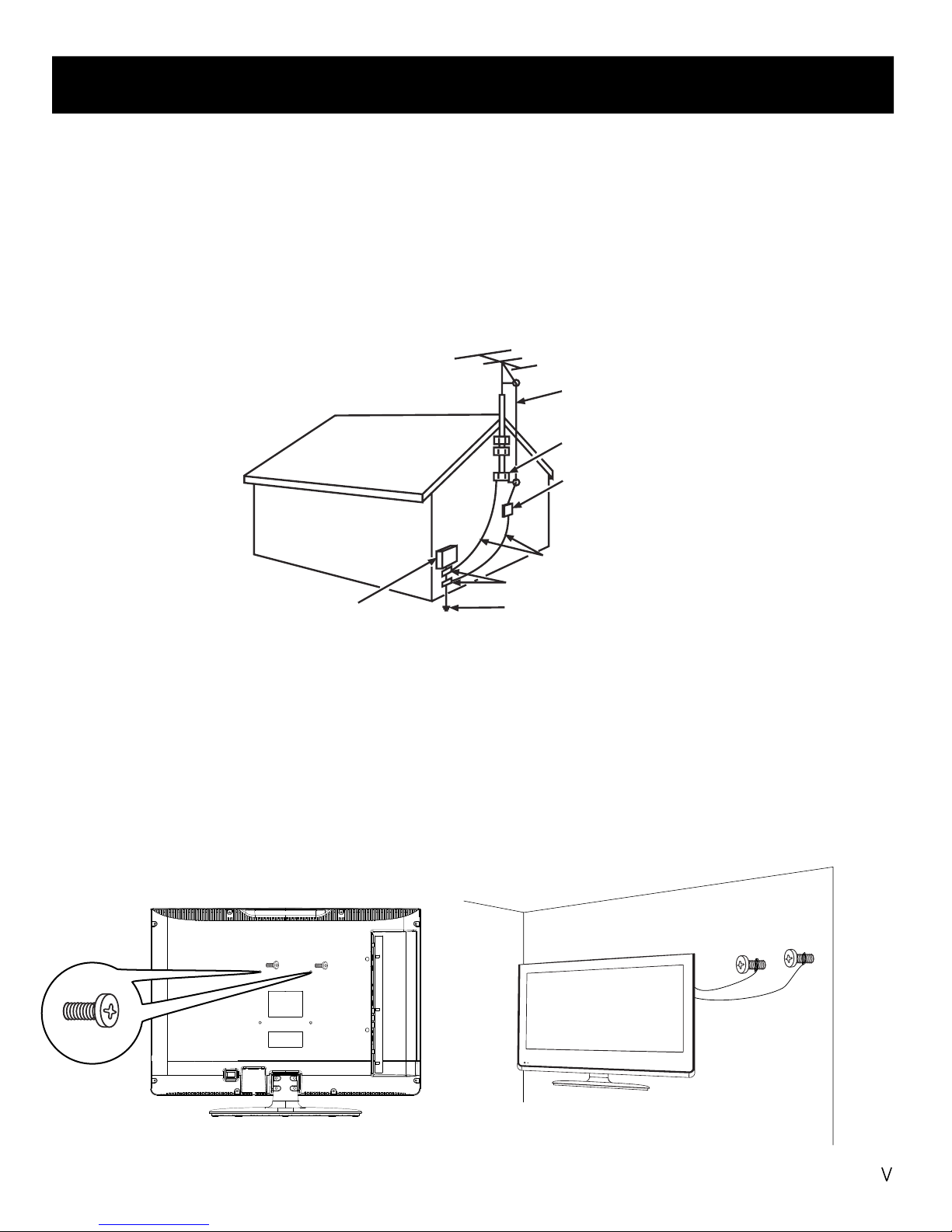
25. If an outside antenna or cable system is connected to the TV, be sure the antenna or cable system is grounded to provide
some protection against voltage surges and built-up static charges. Section 810 of the National Electrical Code,
ANSI/NFPA NO.70, provides information with respect to proper grounding of the mast and supporting structure,
grounding of the lead-in wire to an antenna discharge unit, size of grounding conductors, location of antenna discharge
unit, connection to grounding electrodes, and requirements for the grounding electrode. (See Diagram Figure A.)
24. To reduce the risk of electric shock, the grounding of center pin of plug must be maintained.
Safety Precautions
AN TENN A
LE AD I N
W
IRE
GR OUND C
LA MP
GR OU ND ING CON DUC T ORS
(N EC S
EC TI ON 81 0-2 1)
GR OUND C
LA MPS
PO WER SER VIC E G R OU NDI NG
E
LE CTRO DE S
YS TEM
(N EC A R T 250 , PA RTH)
EL EC TR IC SERV ICE
E
QU IP ME NT
A
NT ENNA
D
IS CHAR GE UNI T
(
NE C S
EC TI ON 81 0-2 0)
23. WARNING: To prevent injury, this apparatus must be securely attached to the floor/wall in accordance with the
installation instructions.
Diagram Figure A
Safety Strap
Caution: Pushing, pulling or climbing on the TV may cause the TV falling. Do not let chlidren climb or hang on the TV.
Always place the TV on a sturdy, level, sable surface that can hold the weight of TV. And if possible, secure the TV according
to the instruction below (Note: The fastening components such as screws are not supplied with TV).
Step one: Insert the M4 mounting screws into the upper two wall mounting screw holes and fasten them (Figure A).
Step two: Insert anchors to wall and connect the bolts and anchors with ropes or chains (Figure B).
Figure A Figure B
M4 Screws
Wall
Page 7

....................................................................................................................................
Child Safety Guide
6
i
Table of Contents
Caution and Warning
....................................................................................................................................
......................................................................................................................................................
......................................................................................................................................
..................................................................................................................................
......................................................................................................................................
..................................................................................................................................
....................................................................................................................................
..................................................................................................................................
......................................................................................................................
FCC Notice
Preparation for Your New TV
Check Accessories
8
8
Setup TV Table Stand
8
Select TV Location
8
Connection and Using
8
TV Stand Installation
9
Safety Precautions
.................................................................................................................................................
.................................................................................................................................................
........................................................................................................................................
................................................................................................................................................
..........................................................................................................................................
....................................................................................................................................................
......................................................................................................................................
..................................................................................................................................
.................................................................................................................................
.............................................................................................................................
..................................................................................................................
......................................................................................................................................
..............................................................................................................................
.......................................................................................................................................
...............................................................................................................................
...................................................................................................................................
..........................................................................................................................................
..................................................................................................................................
..................................................................................................................................
.............................................................................................................................
.........................................................................................................................
...............................................................................................................
......................................................................................................................
........................................................................
..........................................................................
...............................................................................................
...............................................................................................
.................................................................................................................
.................................................................................................................
TV Signal Connection 10
Cable Connections 11
Side Panel Connections
TV Jacks Explanation
Top Panel and Front Panel
12
12
13
14
15
15
16
17
Connecting AV Composite Video device (Good Video Quality)
Connecting YPbPr Component device (Better Video Quality)
Initial Setup 20
20
20
Menu Language
Signal Type
20Auto Channel Search
Connecting HDMI device (Best Video Quality)
Connecting a Computer
How to Obtain Various Kinds of Input Sources
Basic Operations 21
21
21
21
21
22
Turning On and Off
Choosing TV Channel
Selecting Input Source
Adjusting TV Stand Angle
Channel Bar
22
22
Adjusting Volume
EPG (Electronic Program Guide)
17
17
Top Panel Buttons
Front Panel
Remote Control Instructions
18
18
18
Inserting Batteries in the Remote
Learning about Remote Control
19
19Remote Control Buttons
Remote Control Reception Angle
Page 8

7
Table of Contents
OSD Menu Operations
.............................................................................................................................
.............................................................................................................................
.........................................................................................................................................
..........................................................................................................................
................................................................................................................
................................................................................................................
....................................................................................................................
............................................................................................................................................
............................................................................................................................................
............................................................................................................................................
.....................................................................................................
..........................................................................................................................................
..........................................................................................................................................
................................................................................................................................................
23
23
23
25
26
27
31
33
34
35
37
Adjust the OSD Screen
Picture Menu
Sound Menu
Channel Menu
Parental Menu
Frequently Asked Questions (FAQs)
Troubleshooting
V-Chip Rating Explanations
37
37
38
41,42
Warranty Card ........................................................................................................................................
43,44
Warranty Card (Spanish) ......................................................................................................................
............................................................................................................
Wall Mounting Unit Specification
39
.................................................................................................................................
Product Specification
40
US V-Chip Rating System
Canadian English Rating System
Canadian French Rating System
Setup Menu
Others Menu
Page 9
USER’S
GUIDE
Model Number.
19LA30RQ
Part No.: RN03185E0208
Please register your product at
www.rca.com
English
Please keep your sales receipt and keep the record of
the serial number and the date of purchase in order to
receive warranty parts and service.
The serial number is located at the back of the TV.
REMOTE CONTROL
GUIDE
QUICK START
GUIDE
Quick Start Guide
Remote Control Guide
Program Your Universal Cable
or Satellite Remote Control to
Operate Your New RCA TV!
If you would like to program your other
household remote controls to your new RCA
television, please consult the User’s Manual
supplied by your Cable or Satellite provider.
The Cable or Satellite providers’ User’s Manuals
should include instructions on how to program
their remote to your television.
Below is a list of RCA codes for the most
common Cable and Satellite providers.
Use the RCA code that is associated with your
Cable or Satellite provider (if applicable).
If the RCA code associated with your Cable or
Satellite provider is not listed above, if the code
above does not work, or if you can not locate the
instructions for programming your household
remote to your television, call your local Cable or
Satellite provider’s customer service center.
DIRECTV..........................0178,10178
Time Warner Cable...........0178,10178
Comcast..................................10178
Cox Communications..................0178
Dish Network.............................627
Fios Verizon.....0205,0057,0493,0775
This is for U.S. customers
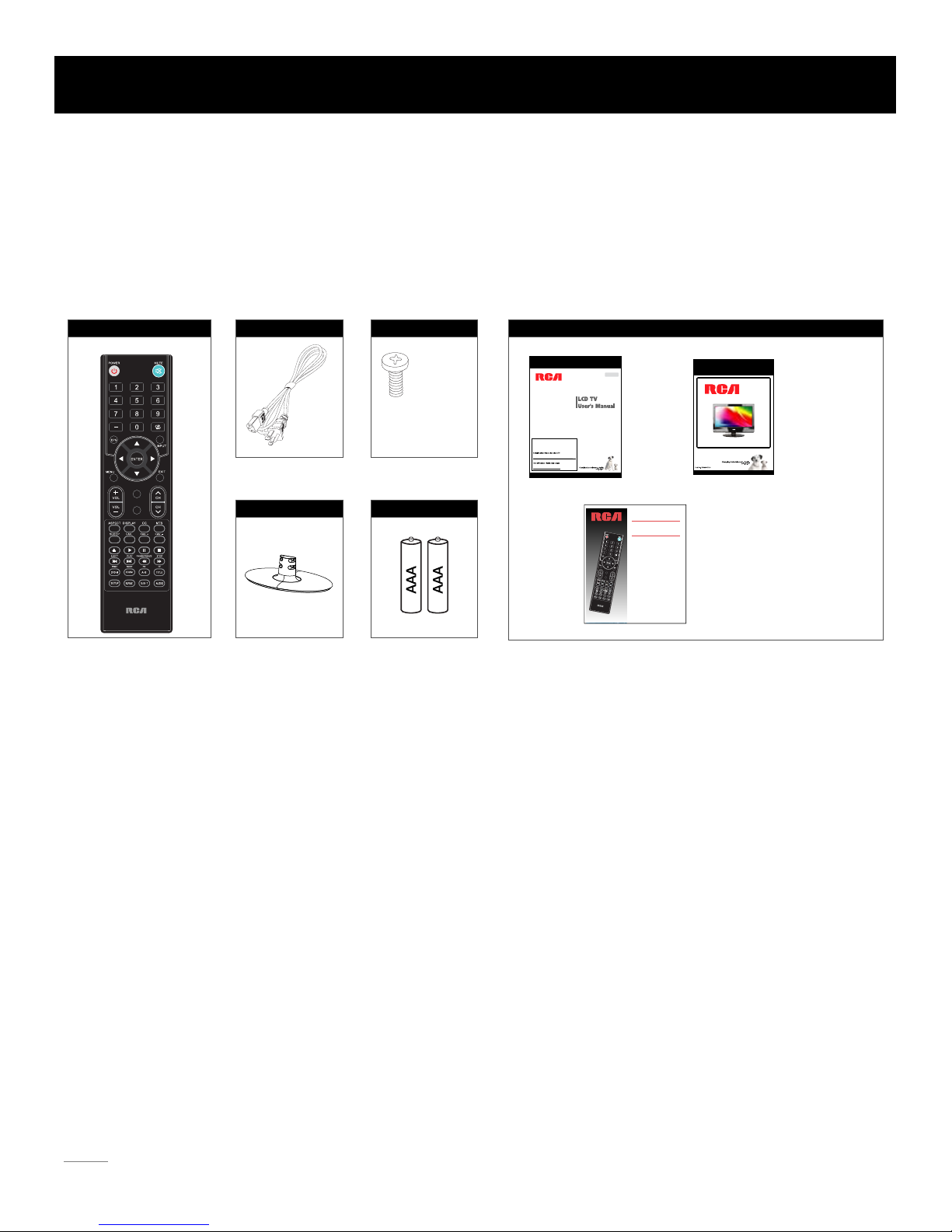
Note: Above accessories are subject to change without notice.
Preparation for Your New TV
8
Before Turning On TV
Check Accessories
Check the accessories that are packed with your TV.
Select TV Location
Select a flat, stable table to locate your TV set. Please follow the Safety Instructions when locating the TV.
Setup TV Table Stand
Please refer to TV Stand Installation guide in next page to carry out stand installing.
Connection and Using
After placing your TV properly, you can connect the TV with power supply and cable components. For further information, see page
12 to page 15.
MACHINE
SCREWS
M4 x 8mm, 4pcs
Part# RS01TM408H
PART NO.: RE20QP83
REMOTE CONTROL AC POWER CORD TV STAND SCREWS
TV STAND AAA BATTERIES
DOCUMENTS
PICTURE
SOUND
PICTURE
SOUND
Page 10
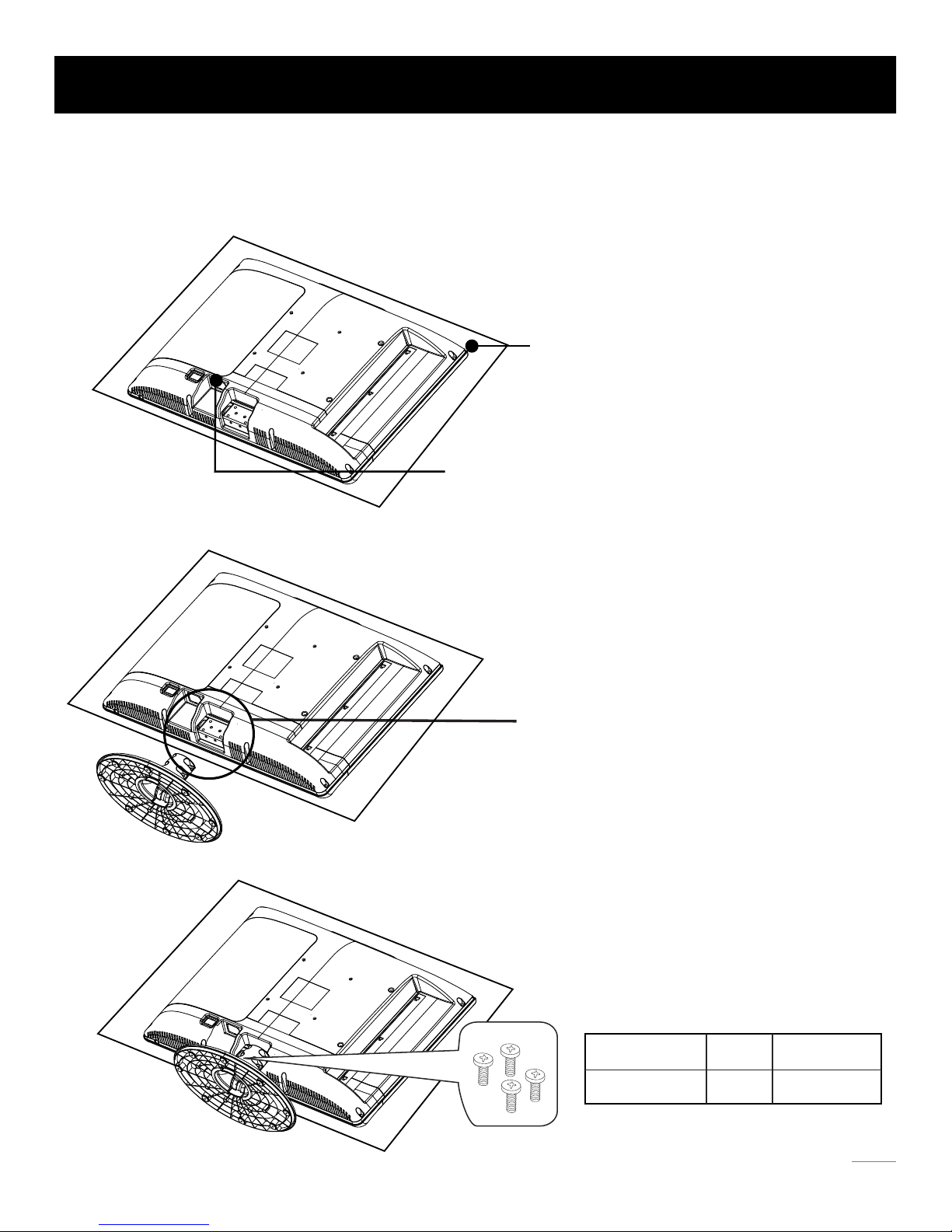
TV 19LA30RQ is packaged with the TV stand separated from the cabinet. To setup the TV table stand, please carry out the
installation according to the instructions below.
The LCD panel is easy to scratch, so please:
1. Choose an absolutely flat surface to place the TV on.
2. Use soft cloth or cushion to face the TV panel.
Do not put TV on the table directly.
Always unplug the AC cord first when installing/removing the stand.
Align the four holes in TV stand body to the screwholes
in TV stand base.
Step One
Place the TV faced down on a soft cloth or cushion to prevent the LCD
panel from being damaged.
Step Three
Insert the four M4 machine screws (which are totally the same) and tighten them.
Step Two
Put the stand body (plastic) onto the stand base (steel) in cabinet.
TV Stand Installation
9
RS01TM408H
Pedestal Screws Quantity Part #
4pcsM4 x 8mm
Page 11
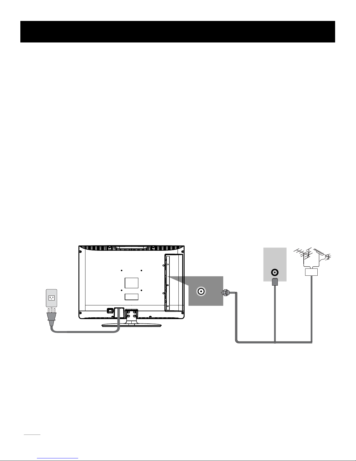
The first step in connecting your TV is obtaining the signal. Your TV 19LA30RQ has a side panel, which allows you to receive analog
and/or digital television channels via TV jack.
B
efore c
onnecting your TV, determine using an antenna or a cable service to obtain the signal.
A. Antenna
Connect the antenna to TV via coaxial cable on TV jack of the side panel. You are ready to receive air local digital and
analog channels.
B. Cable TV service
Connect the cable TV wall jack to TV via coaxial cable on TV jack of the side panel. You are ready to receive off-air local digital
and analog channels.
C. Set-Top Box
If you use a set-top box, you may need to call your cable company or satellite service provider, which use a special connection,
please refer to the user’s guide of set-top box.
Note: Do not plug the AC cord until you have accomplished all the connections.
TV Signal Connection
10
TV
AC Power Cord
(Connect after all the other connections are done.)
AC 110V/60Hz
AntennaCable TV
Or
WALL
OUTLET
Page 12
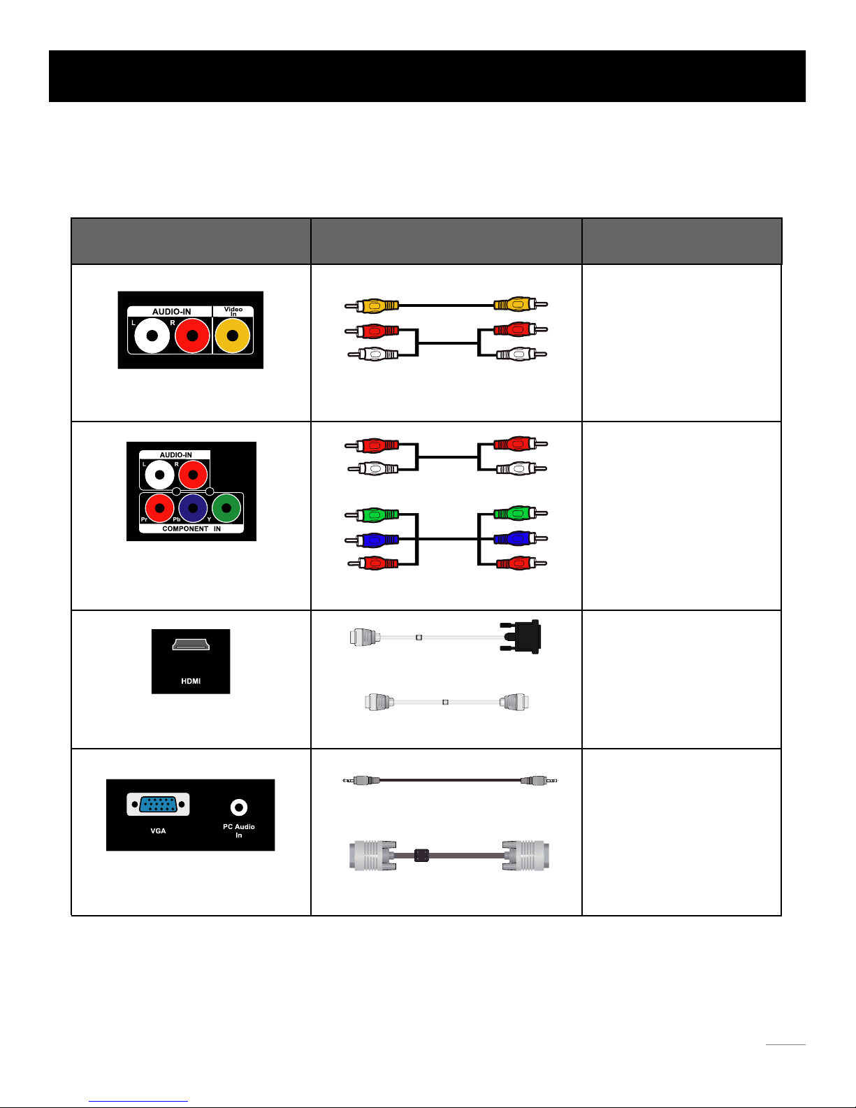
Choose Your Connections
TV 19LA30RQ supports various of connecting ways from other devices (such as DVD, VCR, Set-top box, ect.). Please follow the
table sheet to choose the cables which adapt to your device.
HDMI cable
TM
Note:
HDMI, the HDMI logo, and High-Definition Multimedia Interface are trademarks or registered trademarks of HDMI Licensing LLC
Caution:
Unplug the AC cord when you connect other devices to TV.
Cable Connections
Jacks Cables Further Information
Audio Cable
Audio cable with 3.5mm terminal
VGA cable
COMPONENT video cable
Video/Audio cable
Go to page 12
Go to page 13
Go to page 14
Go to page 15
11
HDMI-DVI cable
AUDIO-IN L and R
COMPONENT IN Y, Pb, Pr
AUDIO-IN L and R, Video In
HDMI
VGA, PC Audio In
Page 13
Audio
L R
Audio
L R YPbPr
Video
HDMI
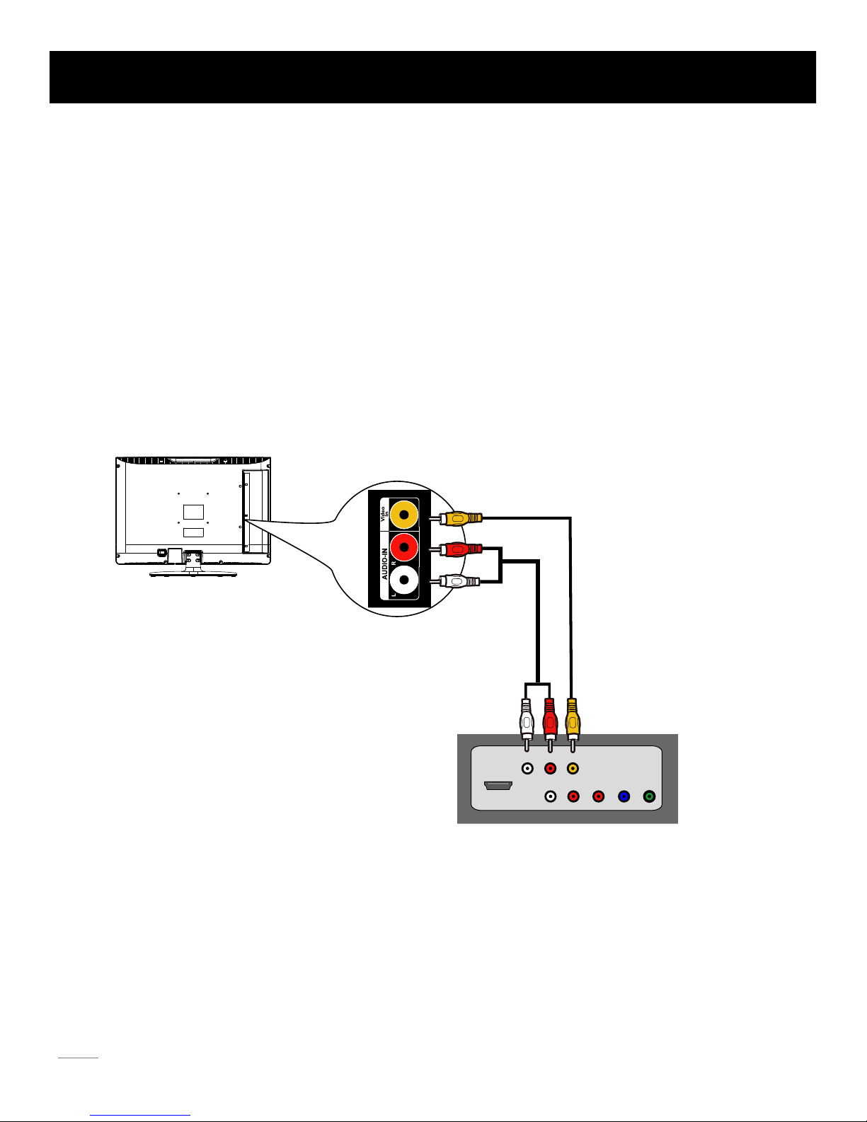
Side Panel Connections
Connecting AV Composite device (Good Video Quality)
To connect an composite AV device, such as a DVD player, follow these steps:
1. Connect the Video In jack on the side of TV to the video output
jacks of device via video cable (yellow).
2. Connect the AUDIO-IN L and R jacks on the side of TV to the aud
io output jacks of device via audio cable.
Notice the left channel jack and plugs are white and the right channel jack and plugs are red.
Composite Video Connection
The picture below is an example of a connection using the composite video jack.
Note: AV signal belongs to composite video. This kind of video signal has regular good display quality.
12
The back of TV
The output panel of other device
Page 14
Audio
L R
Audio
L R YPbPr
Video
HDMI
The output panel of other device
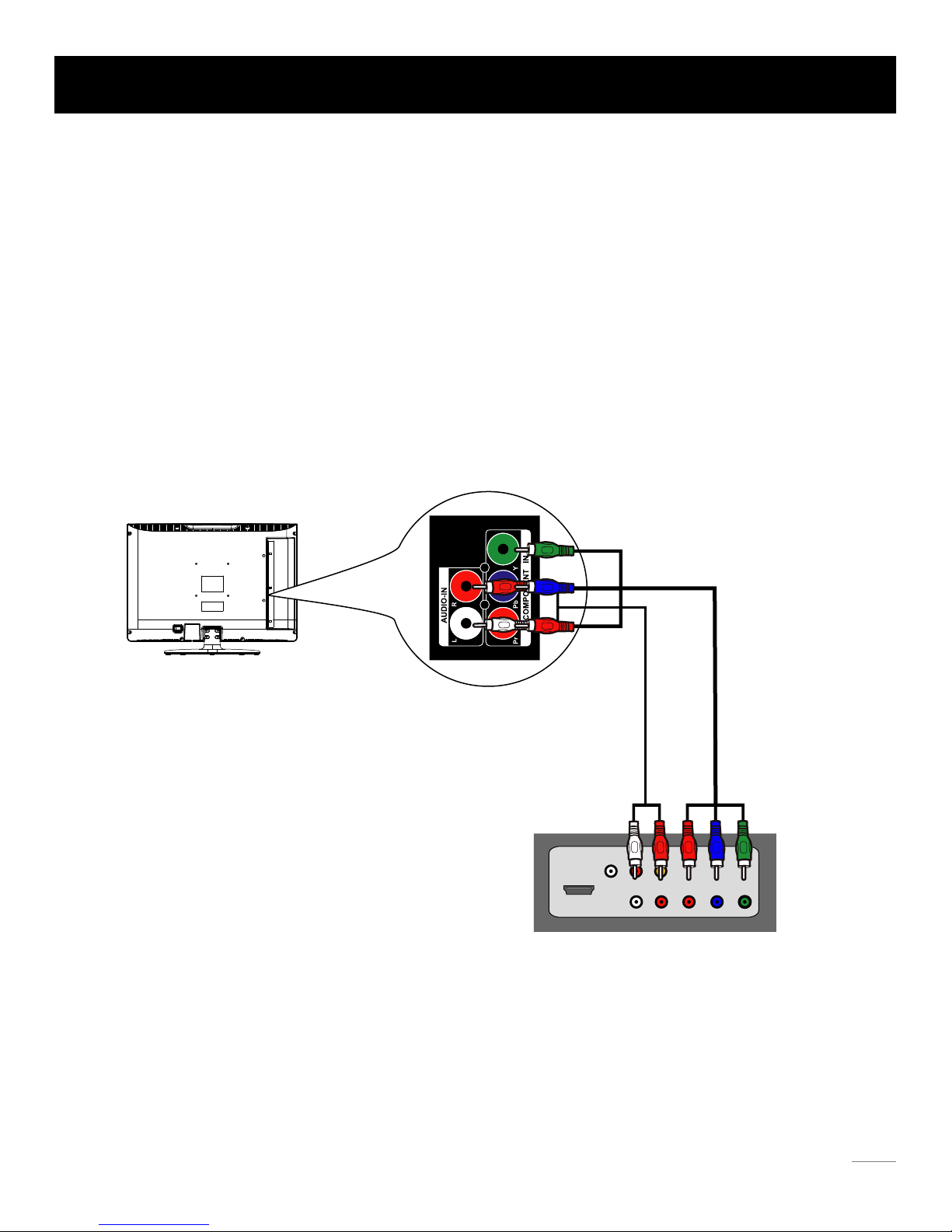
Side Panel Connections
Connecting YPbPr Component device (Better Video Quality)
To connect a component device, such as a DVD player, follow these steps:
1. Connect the COMPONENT Y/Pb/Pr jack on the side of TV to the vid
eo output jacks of device via video cable (green, blue
and red).
2. Connect the AUDIO-IN L and R jacks on the side of TV to the aud
io output jacks of device via audio cable.
Notice the left channel jack and plugs are white and the right channel jack and plugs are red.
Component Video Connection
The picture below is an example of a connection using the component video jack.
Note: Y/Pb/Pr jacks are component video. This kind of video signal has better display quality.
13
The back of TV
Page 15

Side Panel Connections
Connecting HDMI device (Best Video Quality)
14
The back of TV
To connect an HDMI device, such as a DVD player, please connect the HDMI jack on the side of TV to the output jack of
device via HDMI cable.
To connect an DVI device, such as a computer via DVI port of PC and HDMI jack of TV:
1. Connect the HDMI jack on the side of TV to the DVI port of PC via HDMI-DVI cable.
2. Connect the PC Audio In jack on the side of TV to the audio output jack of computer with audio cable (3.5mm stereo jack).
T
o connect an DVI device, other AV device via DVI port of device and HDMI jack of TV:
1. Connect the HDMI jack on the side of TV to the DVI port of device via HDMI-DVI cable.
2. Connect the PC Audio In jack on the side of TV to the audio output jack of device with audio cable (dual-channel RCA
jacks to 3.5mm stereo jack).
HDMI Connection
The picture below is an example of a connection using the HDMI video jack.
Note: 1. HDMI (High-Definition Multimedia Interface) is a compact audio/video interface for transmitting uncompressed digital
data. It carries the audio and video signal via the same cable and has the best display quality.
2. HDMI-DVI cable transfers only video signal from DVI port of DVI device to HDMI jack of TV. For audio signal, please
connect audio output to PC Audio In jack on TV back panel.
Audio Out
L R
DVI
Speaker or
headphone
DVI
Audio
L R
Audio
L R YPbPr
Video
HDMI
The output panel of HDMI device
The output panel of other AV device
PC
Page 16

Side Panel Connections
Connecting a computer
To connect a computer, follow these steps:
1. Connect the VGA port on the side of TV to the VGA output jack o
f device via D-sub 15-pin cable.
2. Connect the PC Audio In jack on the side of TV to the audio out
put jack of computer with audio cable (3.5mm).
PC Connection
The picture below is an example of a connection using your TV as a PC monitor.
How to Obtain Various Kinds of Input Sources
After connection is done, press INPUT button on remote control or TV top panel to choose the input source you need.
See page 21, Basic Operation of TV.
Note: If you want to use your TV as a monitor, please notice that the maximum resolution for 19LA30RQ is 1366*768.
Please set the computer graphic correctly.
15
The back of TV
Speaker or
headphone
VGA
PC
Page 17

TV Jacks Explanation
TV: Connect to receive the signal from your antenna or cable via coaxial cable.
Head phone:
Connect a 3.5mm headphone for personal audio.
AUDIO-IN L/R, Video In: Connect an AV device that has composite video jacks, such as a VCR
• Audio L:
Left audio channel connection. The left audio connector is usually white. For mono audio
sources, be sure to use the left AUDIO INPUT.
Use 3.5mm stereo mini-pin cable to connect PC to TV.
• Audio R: Right audio channel connection. The right audio connector is usually red.
COMPONENT IN Y/Pb/Pr: Connect a device that has component video jacks, such as a DVD player.
• Y/Pb/Pr (Component Video): T
hey provide good picture quality because the video signal is separated into three components.
Use three video-grade or component video cables for the connection. When using Y/Pb/Pr, make sure you connect left and
right audio cables to the Audio L and Audio R jacks.
HDMI: (High-Definition Multimedia Interface) It provides an uncompressed digital connection that carries both video and audio data
by way of an integrated mini-plug cable.
VGA: Connect your computer or other device with a VGA output to this jack using a 15-pin, D-sub cable.
PC Audio In: Use to obtain sound when a PC is connected to the PC input.
SERVICE: For service use only. Do not connect any device.
or a DVD player. To access device connected to these jacks, press the INPUT button on your
remote; then press the up/down arrow to select AV. Press the ENTER button at last to confirm.
To access device connected to the Y/Pb/Pr jack, press the INPUT button on your remote; then press the up/down arrow to
select Component. Press the ENTER button at last to confirm.
Note:•
The AV input (Video In), Component input (Y, Pb, Pr) share the
same audio input jacks-AUDIO IN L/R.
16
Page 18

Top Panel and Front Panel
Top Panel Buttons
Front Panel
If you cannot locate your remote, you can use the top panel buttons on your TV to operate many TV features.
INPUT:
MENU: Displays the TV Main Menu.
Displays the Source Select List.
VOL-: Decreases the volume. In the TV menu system, it acts like the left arrow on the remote control and can be used to
select menu options.
VOL+: Increases the volume. In the TV menu system, it acts like the right arrow on the remote control and can be used to
select menu options.
CH : Scans down through the channel list. In the TV menu system, it acts like the down arrow on the remote control and can
be used to select menu options.
CH : Scans up through the channel list. In the TV menu system, it acts like the up arrow on the remote control and can be
used to select menu options.
POWER ( ): Turns the TV on and off.
About remote control working distance and angle, see page 18.
Power/Standby Indicator: Green and red dual-color LED. It shows red when the TV is turned off and green when turned on.
Remote Control Sensor: Remote control IR sensor, which receives infrared ray sent by remote control.
Remote Control Sensor
Power/Standby Indicator (green/red)
17
Page 19

Inserting Batteries in the Remote
Remote Control Reception Angle
• Remove the cover of battery cabin on the back of the remote control by pushing the tab and sliding the cover.
• I
nsert two AAA batteries, making sure the polarities (+ and -) are aligned correctly.
• P
lace the cover back.
• A
re the polarities (+, -) correct?
• A
re the batteries worn out?
• I
s there an AC power failure?
• I
s the power cord plugged in?
• I
s there any interference or block near the remote
control sensor?
Use your remote control within the distance and angle range shown below.
If the remote control does not work, check these points:
• U
sed batteries should be recycled.
• K
eep out of children’s reach.
• D
O NOT use new and old batteries together.
• C
hange both the batteries at the same time.
• W
hen not using the remote control for a long time,
remove the batteries from the unit.
CAUTION:
7 meters
Remote Control Instructions
18
Universal Remote Control Code List
For Universal Remote Control brands listed
below, please use accompanying codes and
refer to your Universal Remote ControlUser
Manual for basic Instruction for changing TV
code to operate the TV model.
Codes for DIRECTV: 0178, 10178
Codes for Time Warner Cable: 0178, 10178
Codes for Cox Communications: 0178
Codes for Comcast: 10178
Codes for Dish Network: 627
Codes for Fios Verizon: 0205, 0057, 0493, 0775
Page 20

Remote control part number RE20QP83
Remote Control Buttons
Numeric Buttons: Use these buttons to enter numbers.
To enter a digital channel with a sub-channel, enter the main channel; then, press this
button to enter the sub-channel and press ENTER.
Arrows ( / / / ):
Recall ( ):
EPG:
Uses the four arrows to highlight different items in the TV menu or
change the value. The up/down arrow can also work as CH /CH
button, and the left/right arrow can also work as VOL-/VOL+ button.
CH or CH : Scans up or down through the current channel list. Press once to change
the channel up or down; press and hold to continue changing channels.
PICTURE: Switches between the preset picture mode (see page 23).
SOUND: Switches between the preset sound mode (see page 25).
The keys not listed are for DVD control, they are not available for this TV model.
NOTE :
Returns to the previous channel.
Shows Electronic Program Guide (see page 22).
INPUT:
ENTER:
Accesses the available input channels (TV, AV, Component, HDMI, PC).
Enter and confirm button.
Use the arrows to highlight options, and press ENTER to select.
MENU: Accesses the Main Menu, or return to the upper level of a sub-menu.
EXIT: Exits the current menu or function.
MUTE ( ):
“ ”:
Reduces the TV volume to its minimum level. Press again to restore the volume.
ASPECT: Switches between the preset screen size mode (see page 24).
DISPLAY: Displays the Channel Bar (see page 22).
CC: Selects the closed caption.
MTS: Selects the multi-channel television sound.
Scans up or down through the current favorite channel list.
FAV.: Adds the current channel to your favorite list, or erases the current channel from
FAV.+ or FAV.- :
Freeze the current screen frame, press again to return to normal.PAUSE/FREEZE :
your favorite list (if this channel is a favorite channel already).
SLEEP: Selects the sleep timer, after which the TV will shut off automatically.
VOL+ or VOL-: Increases or decreases the TV volume.
POWER ( ): Turns the TV on or off.
Learning about Remote Control
19
PICTURE
SOUND
Page 21

:Skip
:Stop Auto Channel Search
ENTER
MENU
AUTO CHANNEL SEARCH - Air
Analog Channels Found: 1
Digital Channels Found: 0
3%
Return
Now Searching... Please Wait...
If it is the first time you turn on your TV, or you have done Clear Channel List option (see page 30), the initial setup menu appears
automatically.
Menu Language
To choose your menu language, press the left/right arrow until the language you need appears.
Available languages: English, French and Spanish.
To choose your TV tuner signal type, press the left/right arrow until Air or Cable appears.
Note: please select TV signal type according to the antenna or cable closed circuit TV you use.
Signal Type
To execute auto channel search, press the up/down arrow to highlight Auto Channel Search and press ENTER button.
What to notice:
1. The channel search access starts from the Analog TV channel searching and ends at Digital TV channel searching.
2. The channels that have been found will be stored automatically.
Auto Channel Search
Initial Setup
Menu Language English
Air
Execute
Signal Type
Auto Channel Search
:Change Setting
:Move
:Return
MENU
Initial Setup
20
3. You can press MENU button to skip analog/digital channel searching.
4. You can press ENTER button to end the channel searching.
Page 22

Adjusting TV Stand Angle
The TV cabinet can lean forward 5 degrees and backward 15 degrees from the TV table stand.
You can adjust the leaning angle for the best viewing effect and comfort.
5° 15°
Basic Operations
Turning On and Off
Connect the AC cord to power the LCD TV. At this time the TV will enter standby mode and power indicator shows red.
Use Power button ( ) on the top panel of TV or on the remote control to turn on the TV. After switching off the TV for 5 seconds,
you can turn on TV again.
Press INPUT button on remote control to display Source Select list.
Use up/down arrows to highlight the source you need and press ENTER to confirm.
Selecting Input Source
Source Select
TV
AV
Component
HDMI
PC
21
Tuning To Analog Channels
An analog channel has a channel number beginning with “A”. Input the digital number with numeric buttons directly and press
ENTER button to confirm.
For example, to watch analog channel “A51”, press “5”, “1”, “ENTER” on remote control in sequence.
Tuning To Digital Channels
Note: Although there is no analog TV signal available in America, we reserve ATV functions for some expansible use.
A digital channel has a channel number beginning with “D”. Input the main digital number with numeric buttons directly, then press
“ ” button on remote control, and input the sub number at last.
For example, to watch analog channel “D31-1”, press “3”, “1”, “ ” button. “ENTER” on remote control in sequence.
You can use CH button to increase channel number and CH to decrease channel number. When no OSD (On Screen
Display) is used, the up/down arrows can also work as CH /CH buttons.
Changing Channels Directly
Choosing TV Channel
Page 23

D50 - 1
KOCE-HD
Smart Travels - Pacific Rim with Rudy Maxa
23 : 00 - 23 : 30
Stockholm & Sweden is a natural-born beauty, winning us over with
luxuriant landscapes and sleek Scandinavian style. We cruise through Stockholm’s
sun-dappled archipelago, visit a designer hotel and sip cocktails in the trendy Ice Bar
(a lounge...
:Page
:Return
MEN U
Page 1/2
Mono
A2
480i
Air
Oct-31 23.14 Mon
English
KOCE-HDM
TV
D50 - 1
1080i
Oct-31 23:14 Mon
Air
Channel Bar
Press the DISPLAY button on the remote control, the channel bar will appear on the right top of screen. It displays the current
channel’s information. T
he following list describes the items on the channel bar.
Adjusting Volume
Press the VOL+/VOL- button on the remote control to adjust the volume. If you want to switch sound off, press MUTE ( ).
EPG (Electronic Program Guide)
Press EPG button on the remote control, the electronic program guide will appear in the center of screen.
The electronic program guide gives the TV program playing project. You can use left/right arrows to switch pages.
When OSD (On Screen Display) is not used, the arrows left/right can also work as VOL-/VOL+ butttons.
A2/D50-1
MTV/KOCE-HD
ATV DTV
If the channel is analog, A is displayed. If it’s a digital channel, D is displayed. For example, in the pictures
above, A2 is an analog channel, and D50-1 is a digital channel ( -1 is a sub-channel number).
Displays the channel label.
Mono/English Displays whether the current channel is being broadcast in stereo or mono. If the current channel is digital,
this space will be SAP (Second Audio Program) language.
480i/1080i Displays the signal resolution.
16:9/CC/TV-PG Displays the screen aspect ratio, closed caption and TV rating level of the current program or channel.
And these are only available for digital channels.
Oct-31 23:14 Mon Current date and time.
Basic Operations
22
Page 24

Contrast: Adjust the contrast of color.
:Change Setting
:Move
:Return
MENU
Brightness
Contrast
Color
Tint
Sharpness
Picture Mode Standard
PICTURE SETTINGS
:Move
:Return
MENU
:Go to Next Menu
/
ENTER
PICTURE
Screen Size Wide
PC Settings
Color Temperature Normal
Advanced Picture Settings
Picture Setti ngs
PICTURE
SOUND CHANNEL PARENTAL SETUP OTHERS
Adjust the OSD Screen
The OSD (On Screen Display) menu enables you to approach to the TV functions.
To use OSD menu system, press MENU button on remote control, then use left/right arrow to highlight an option from PICTURE,
SOUND, CHANNEL, PARENTAL, SETUP or OTHERS and press ENTER button.
Press the up and down arrow to move to a different option within each menu. If necessary, press ENTER or right arrow to display
the choices of the option you’ve highlighted. If available, use the text at the bottom of each screen for help. To return to the
previous menu, press the MENU button.
To exit the OSD menu:
• Press the EXIT button. The menu will clear from the screen.
• Press the MENU button repeatedly until the menus disappear.
Picture Menu
Picture Settings
The Picture Menu contains menus and controls to configure the way the picture appears. The Picture Menu options apply to the
video for the main TV and VIDEO INPUT selections. All picture options can be applied to each input.
Press MENU on the remote. Select Picture from the Main menu. Press the ENTER button to proceed to PICTURE menu.
Picture Settings: Choose the preset visual mode of your TV:
Use up/down to choose the function you need, press
ENTER or right arrow to adjust or enter a sub-menu. The
sub-menu image and explanation are shown below.
Standard, Movie, User, Dynamic. Only in User mode you can
adjust Brightness, Contrast, Color, Tint and Sharpness.
Brightness: Adjust the brightness of picture.
Color: Adjust the richness of color.
Tint: Adjust the balance between red and green level (only
available in NTSC signal.
Sharpness: Adjust the sharpness level of picture.
OSD Menu Operations
23
Page 25

Screen Size
:Move
:Return
MENU
:Go to Next Menu
/
ENTER
PICTURE
Screen Size Wide
PC Settings
Color Temperature Normal
Advanced Picture Settings
Picture Setti ngs
Screen Size
Color Temperature
This option allows you to select one of three automatic color adjustments: Cool for a bluer palette of picture colors; Normal or
Warm for a redder palette of color.
:Move
:Return
MENU
:Press to Execute
ENTER
Horizontal Position
Vertical Position
Clock
Phase
Auto Adjust Execute
Reset Execute
PC SETTINGS
PC Settings (only available in PC mode)
Auto Adjust: Adjust the PC picture display automatically.
Horizontal Position: Adjust the horizontal position of picture.
Phase: Adjust the phase of picture.
Reset: Reset all the PC picture settings to factory default.
Vertical Position: Adjust the vertical position of picture.
Clock: Adjust the clock of picture.
:Change Setting
:Move
:Return
MENU
Film Mode
Noise Reduction
MPEG Noise Reduction
Dynamic Contrast Off
Off
Medium
Off
ADVANCED PICTURE SETTINGS
Advanced Picture Settings (not available in PC mode)
Dynamic Contrast: Set dynamic contrast on/off.
Film Mode: Set film mode on/off.
Noise Reduction: Set noise reduction as Off/low/Medium/High.
MPEG Noise Reduction: Set MPEG noise reduction as Off/low/Medium
or High.
Note: Noise reduction helps to reduce the picture “static” or any type of
interference. This feature is especially useful for providing a clearer picture
in weak analog signal conditions. The MPEG Noise Reduction specifically
works on video signal with MPEG coding.
OSD Menu Operations
24
Screen Size: Select a screen aspect ratio.
(Available ratio: Wide, Cinema, Zoom, and Normal.)
Please choose the ratio that applies to your video signal format
best.
Page 26

:Change Setting
:Move
:Return
MENU
Sound Mode Standard
SOUND SETTINGS
Bass
Treble
Balance
:Move
:Return
MENU
:Go to Next Menu
/
ENTER
Surround Mode
Analog Sound Stereo
Auto Volume
EnglishDigital Sound
Equalizer Settings
Sound Settings
SOUND
Sound Menu
Sound Settings
The Sound Menu lets you adjust audio output. To access the Sound Menu, press MENU on the remote, and then select SOUND
from the Main Menu. Press ENTER button to proceed to SOUND menu.
Use up/down to choose the function you need, press
ENTER or right arrow to adjust or enter a sub-menu. The
sub-menu image and explanation are shown below.
Sound Mode: Choose the preset sound mode of your TV:
Standard, Soft, User, Dynamic. Only in User mode you can
adjust Bass, Treble and Balance.
Bass: Adjust the bass component of TV sound.
Treble: Adjust the treble component of TV sound.
Balance: Adjust the balance between the left and right channel.
OSD Menu Operations
25
Surround Mode
Creates a 3D sound surround from standard stereo material, with deep and rich enhancement.
Auto Volume
Set auto volume control on/off.
Analog Sound
Select analog TV audio sound type: Stereo, Mono or SAP (only available in TV mode).
Digital Sound
Select digital TV audio language type: English, French or Spanish (only available for DTV channel).
Page 27

:Move/Page
:Return
MENU
:Select
ENTER
Enter a channel label to rename the current channel.
Set if the current channel is the favorite channel.
Set if the current channel is skiped.
CHANNEL SETTING
A4
D50-1
D50-2
D50-3
Channel
KOCE-HD
KOCE-SD
KOCE-LB
LabelSkip Favorite
Press up/down arrow to switch the channel you want to edit.
Page 1/1
A2
:Move
:Return
MENU
:Go to Next Menu
/
ENTER
CHANNEL
Favorite List
Channel Setting
Signal Type Air
Auto Channel Search
Channel List
Execute
:Change Setting
:Move
:Return
MENU
Mode Off
EQUALIZER SETTINGS
0
1000250050001K02K04K010K
Equalizer Settings
Channel Menu
The seven-band graphic equalizer allows you to adjust the audio frequency
settings. You can select one of the equalizer presets (OFF, POP, ROCK,
JAZZ) or create your own personal preset (USER).
Press the left or right arrow to select the frequency (100Hz, 250Hz, 500Hz,
1KHz, 2KHz, 4KHz, 10KHz) you want to adjust. Use the up or down arrow
to adjust.
The Channel Menu enables you to search, view and edit channels. It is available in TV mode only.
Press MENU and choose CHANNEL from the Main menu. Press the ENTER button to proceed to CHANNEL menu.
Channel List
Display a channel list. It shows the current channels.
Favorite List
Display a favorite channel list. It shows the current favorite channels.
Channel Settings
Go to channel setting sub-menu (as shown below).
Use up/down to choose the function you need, press
ENTER or right arrow to adjust or enter a sub-menu. The
sub-menu image and explanation are shown below.
OSD Menu Operations
26
Page 28

:Move
:Return
MENU
:Go to Next Menu
/
ENTER
V-CHIP
Canada V-Chip
Block Unrated Show
Downloadable Rating
Clear Downloadable Data
US V-Chip
:Return
MENU
:Enter Password
0-9
PARENTAL CONTROL
V-Chip
Change Password
Keypad Lock
Source Lock
Clear Channel List
Lock Parental Control
Remote
Signal Type
Select your TV signal type: Air or Cable.
Auto Channel Search
Execute an auto channel search (see page 20).
OSD Menu Operations
27
• When the Parental Control Menu is accessed from the Main Menu, you need to enter password to unlock the menu function.
• After unlocking, the items in parental control menu can be used. Use arrow up/down to highlight the function you need and
press ENTER or right arrow to use V-chip, Change Password, Keypad Lock and Source Lock, Clear Channel List sub-menu.
Please enter your four-digit password with numeric keys 0~9.
Note: The original password is “0000”.
V-Chip
Lock Parental Control
The following graphic details where items locate within the V-Chip menu.
US V-Chip
Press ENTER or right arrow to enter US V-Chip ratings menu, which contains two sub-menus: Movie Rating and TV rating.
See next page for more details.
Parental Menu
The Setup Menu enables you to lock program with special content, panel key board and input source.
Press MENU and choose PARENTAL from the Main menu. Press the ENTER button to proceed to PARENTAL menu.
Page 29

:Return
MENU
:Lock/Unlock
ENTER
:Move
TV RATING
TV-Y7
TV-G
TV-PG
TV-14
TV-MA
TV-Y
D
L S V FV
:Move
:Return
MENU
:Lock/Unlock
ENTER
MOVIE RATING
PG
PG-13
R
NC-17
X
G
Movie Rating
TV Rating
Use arrow keys to select the rating level you want to block,
press ENTER to lock/unlock the rating level. If you have
blocked a lower level rating, the higher ratings will be
blocked too.
For example , when PG-13 is blocked, R, NC-17 and X will
be blocked at the same time.
After adjusting, press MENU to return or press EXIT to exit the menu..
TV Rating Overview
Age-Based Ratings
TV-MA Mature Audience Only
TV-14 Parents Strongly Cautioned
TV-PG Parents Guidance Suggested
TV-G General Audience
TV-Y7 Directed to Children 7 Years and Older
TV-Y All Children
D Sexually Explicit Dialogue
L Adult Language
S Sexual Situations
V Violence
FV
For more rating explanation, see page 37.
Fantasy Violence
Content Themes
Similar with Movie Rating.
OSD Menu Operations
28
Page 30

:Move
:Return
MENU
:Lock/Unlock
ENTER
FRENCH RATING
8 ans+
13 ans+
16 ans+
18 ans+
G
:Move
:Return
MENU
:Lock/Unlock
ENTER
ENGLISH RATING
C8+
G
PG
14+
18+
C
Canada V-Chip
Press ENTER or right arrow to enter US V-Chip ratings menu, which contains two sub-menus: English Rating and French Rating.
English Rating
Press ENTER or right arrow to enter English rating menu.
French Rating
Press ENTER or right arrow to enter French rating menu.
Block Unrated Show
Block all the unrated program.
Downloadable Rating, Clear Downloadable Data
Activate or downloadable rating data. if available.
Use arrow keys to select the rating level you want
to block, press ENTER to lock/unlock the rating
level. If you have blocked a lower level rating,
the higher ratings will be blocked too.
For example , when PG is blocked, 14+ and 18+
will be blocked at the same time.
Note: These ratings are
available only if the
broadcaster is sending
rating information.
Similar with English Rating.
OSD Menu Operations
29
Page 31

Keypad Lock
Select this option to block or unblock the TV’s side keypad buttons so that they can’t be used.
Clear Channel List
This option allows you to execute Clear Channel List function.
This function will reset the whole TV system to factory default (not only reset OSD menu).
:Page
:Move
:Return
MENU
:On/Off
ENTER
SOURCE LOCK
Page 1/2
Source Lock
This option allows you to lock or unlock the input source. The source blocked can not be
chosen from input list unless you input the correct parental password.
AV
Component
HDMI
PC
TV
Use up/down arrow
to select the source,
press ENTER to
lock or unlock it.
:Return
MENU
:Enter Password
0-9
CHANGE PASSWORD
New PIN
Confirm
Old PIN
Change Password
Change the password of parental menu.
Input the old password.
Input the new password.
Input the new password again to confirm.
OSD Menu Operations
30
Remote
Select your Remote: Off, Remote1 or Remote2.
This is for special purpose.
:Return
MENU
:Enter Password
0-9
PARENTAL CONTROL
V-CHIP
Change Password
Remote
Keypad Lock
Source Lock
Clear Channel List
Lock Parental Control
Execute
Off
Page 32

:On/Off
:Move
:Return
MENU
CLOSED CAPTION
Analog Caption Type CC1
Service1Digital Caption Type
DefaultDigital CC Preset
Digital CC Style
Caption Display Off
:Move
:Return
MENU
:Go to Next Menu
/
ENTER
SETUP
Menu Language English
Clock
Closed Caption
OSD Menu Operations
Setup Menu
The Setup Menu lets you config the TV with your preferences.
Select SETUP from the Main Menu. Press ENTER button to proceed to SETUP menu.
Closed Caption
Caption Display
Press left/right arrow to select closed caption display on or off.
Analog Caption Type
Press left/right arrow to select analog closed caption type: CC1, CC2, CC3, CC4, TEXT1, TEXT2, TEXT3, TEXT4.
Digital Caption Type
Press left/right arrow to select digital closed caption type: Service1, Service2, Service3, Service4, Service5, Service6.
Digital CC Preset
Press left/right arrow to select digital closed caption preset: Default, Custom.
Digital CC Style
Press left/right arrow to go to digital closed caption style sub-menu (see next page).
Only in custom mode you can adjust the digital closed caption style.
Use up/down to choose the function you need, press
ENTER or right arrow to adjust or enter a sub-menu. The
sub-menu image and explanation are shown below.
31
Page 33

Daylight Saving Time
Set your daylight saving time on or off (needs to turn on auto clock).
:Change Setting
:Move
:Return
MENU
CLOCK
Auto Clock
1980-01-06 18:49:24Setup Time
SunDay of Week
Time Zone Eastern
Daylight Saving Time
:Change Setting
:Move
:Return
MENU
DIGITAL CC STYLE
CC Font Default
DefaultCC Opacity
Default
Default
Text Color
CC Background Opacity
DefaultCC Background Color
CC Size Default
CLOSE CAPTION
Digital CC Style
Clock
Time Zone
Select your time zone: Eastern, Central, Mountain, Pacific, Alaska, Hawaii, Samoa, Newfoundland, Atlantic.
Auto Clock
Select auto clock on/off. Auto clock helps you synchronize your TV time to standard time (from DTV signal).
Setup Time
Set your TV time manually (needs to turn off auto clock).
Day of Week
Display what day it is (can’t be adjust, display only).
Select the item you want to adjust in Digital CC Style menu
with up/down arrows.
After changing, you can preview the caption style here.
OSD Menu Operations
32
Page 34

Note: The OSD’s appearance and color are referred to the actual appliance.
:On/Off
:Move
:Return
MENU
ENTER
OTHERS
No Signal Power Off
No Operation Power Off
All Reset
Audio Only
Blue Back
Execute
Execute
Others Menu
The Others Menu lets you config the TV with your preferences in other features.
Choose OTHERS from the Main Menu. Press ENTER button to proceed to SETUP menu.
Blue Back
Press ENTER button to select Blue Back on or off. If the Blue Back is turned on, the TV will display a blue background
when there is no signal input.
No Signal Power Off
Press ENTER button to select “No Signal Power Off” on or off. If it is turned on, the TV will shut off after 10-minute
no signal time. We suggest you turn on this function when Blue Back is turned on. Because it may hurt the LCD panel
No Operation Power Off
Press ENTER button to select “No Operation Power Off” on or off. If it is turned on, the TV will shut off after a 3-hours
no operation time.
All Reset
Press ENTER button to execute reset to TV system. All the settings will be reset to factory default.
Audio Only
Press ENTER button to activate audio only mode. The TV will output only sound and the LCD panel will be turned off.
To restore normal playing, hold POWER button for three seconds.
if the blue screen lasts too long.if the blue screen lasts too long.
Note: In PC mode, the monitor standby and power off settings depend on the No Signal Off time.
Use up/down to choose the function you need, press
ENTER or right arrow to adjust or enter a sub-menu.
The sub-menu image and explanation are shown below.
OSD Menu Operations
33
Page 35

What’s the most convenient way to view High Definition (HD) video?
Connect an antenna to the TV Input jack to view free local digital channels. You may need to purchase an antenna. (See page10
for more information about antenna setup).
Visit www.antennaweb.org for assistance in deciding what type of antenna to use to receive the local digital channels available
to you. After entering your location, this mapping program tells you which local analog and digital stations are available using a
certain antenna.
Are there other ways to view High Definition (HD) video?
Besides using an antenna as mentioned above, you can also use a set-top box to receive digital video. Contact your cable service
provider or satellite provider to purchase digital programming and have them connect the box to ensure you are viewing channels
in the best way.
How do I tell an analog channel from a digital channel?
Press the DISPLAY button to display the Channel Bar. Look at the top right corner of the screen. An “A” is displayed for an analog
channel. A “D” is displayed for a digital channel.
Note: Since the analog TV in America has been cut off, we reserve analog TV function only for some unexpected use.
Why are there bars on my screen, and can I get rid of them?
Most digital video is sent in a 16/9 format which fills your screen, but is sometimes sent in 4/3 which does not fill your screen. It
depends on how the station or device connected to your TV is formatting the video. If there are bars on the screen, press the
ASPECT button to try a different format that may eliminate the bars. Some bars can't be removed because of the way the format
is sent by the broadcaster. The format changes as you press the ASPECT button and the format type is displayed at the bottom
of the screen. For more information on screen formats, go to page 24.
Why does channel search find a lot of channels, but when I try to tune to them, there’s nothing there?
Some channels don’t carry programming, such as video On Demand. When channels are unavailable, your TV screen is blank or
appears like snow. You probably want to remove these channels from your channel list. Remove these in the Channel List Menu.
Go to page 26 for more information.
Why does it take a long time when I search the channels at first time?
If you have both analog and digital channels, the TV is looking for all available channels in the channel list. If you do have digital
channels, the TV is also searching for scrambled channels, non-scrambled channels, and each sub-channel of that digital channel.
Frequently Asked Questions (FAQs)
34
Page 36

Identifying Problems
If there are any problems when using the product, please consult the list below. If the list does not solve the problem, call our
Customer Service Center immediately.
TV Problems
The TV can’t be turned on.
• Make sure the AC cord is plugged in.
• Check the wall
outlet, make sure the AC output works normally and stably.
• T
he top panel may be locked (disabled). Use the remote control to turn on the TV.
• Select the Keypad Lock function in the PARENTAL Menu and press ENTER to uncheck the locking status.
There is no picture or sound but the TV is on and there is a “No Signal” sign on screen.
• Are you trying to use an input source with no device connected to it? For using other video/audio device, make sure the external
device works normally first, then press INPUT and choose the right input source.
• The Signal Type option may be set incorrectly. Go to page 20 for detailed instr
uctions.
• The channel may be blank. Try to search the channel again or ch
ange another channel.
The sound is fine, but the picture is poor.
• If you can only get black and white pictures from external device that you've connected to your TV, maybe it is due to the video
cables is not connected well, or they are connected wrongly. Check the connection stability first, then check the correctness.
For AV input, the yellow video cable connects to the yellow Video In jack on the side of your TV. For Component input, the three
Y, Pb, Pr video cables (red, blue, and green) should be connect to the corresponding input jacks on the side of your TV.
• Check the antenna connections. Make sure all of the cables are
firmly connected to the TV jack on side of your TV.
• Try adjusting the color features to improve.
There is no sound, but the picture is fine.
• The sound might be muted. Try pressing the MUTE button to restore sound.
• For using AV, Component, remember to connect the device’s left
and right audio output correctly. The left channel
cable is white and the right channel cable is red. Please match the cables and jacks accoding to there colors.
• The sound settings may not be set correctly. Go to page 25 for
more information.
• If your audio source has only one jack or is a (mono) audio sou
rce, make sure you have plugged the connection into the
Audio In L jack (white) on the TV.
Troubleshooting
35
The buttons on the top panel don’t work.
• Unplug the TV from the AC power for 10 minutes and then plug it back. Turn the TV on and try again.
The TV turns off unexpectedly.
• The electronic protection circuit may have been activated because of a power surge. Wait 30 seconds and then turn the TV
on again. If this happens frequently, the voltage in your house may be abnormal. If the other electronic equipment in your home
can’t work normally, consult a qualified service personnel.
• T
he top panel may be locked (disabled). Use the remote control to turn on the TV.
• Select the Keypad Lock function in the PARENTAL Menu and press ENTER to uncheck the locking status.
Page 37

The stereo sound performance is bad.
• It may be a weak station. Use the SOUND Menu and set Analog Sound as Mono.
A black box appears on the screen.
• Closed captioning might be on. Check Closed Caption in the SETUP menu. Go to page 32 for more instructions.
Problems with the HDMI Connection.
• Make sure the HDMI device (DVD, video gamer, etc.) is turned on and the cables are firmly connected. If problems still occur, turn off
your device and reconnect it. Reset the power by unplugging the power cord and plugging it again.
• I
f a “No Signal” message appears on screen , the HDMI device isn’t responding. Contact the manufacturer of the HDMI device for
further assistance.
• I
f you have black bars on each side of your picture (which means the TV can not display a full-screen image), the device you connected
might have a switch or a menu option allowing you to change the picture quality output that will fix this. Choose either 720p or 1080i.
Can’t select a certain channel.
• The channel may be blocked or not approved in the PARENTAL Menu.
• T
he channel may be skipped in channel list in CHANNEL Menu. Check the blocking and skipping status of channel.
Troubleshooting
The Remote control doesn’t work.
• Something might be blocking between the remote control and the remote sensor on the front panel of the TV. Make sure
there is a clear path.
• T
he remote may not be aimed directly at the TV.
• T
he batteries in the remote may be weak, dead, or installed incorrectly. Put new batteries in the remote.
You are experiencing problems with V-Chip/Parental Controls.
• If the rating limits don’t work, you must lock the settings. Go to the Main Menu (press MENU on your remote), select
PARENTAL to check the settings.
What else can I do?
If you’ve been through the Troubleshooting section and nothing has fixed your problem, try rebooting your TV. Note that after
a reboot, you may need to run your TV through the setup process again. To reboot, unplug the power cord from the wall
outlet or power strip. Keep your TV unplugged for about 5 minutes. Then plug in the TV and turn it on. See if the problem
is fixed. If the problem remains, then please visit the Customer Support Menu at www.rca.com or updated FAQs or contact
RCA Customer Support at the support number provided in your Warranty card.
36
Page 38

US V-Chip Rating System
TV-MA (Mature Audience Only): Specifically designed to be viewed by adults and may be unsuitable for children under 17. It
contains one or more of the following content themes: crude indecent language (L),
explicit sexual activity (S), or graphic violence (V).
TV-14 (Parents Strongly Cautioned): Contains some material that many parents would find unsuitable for children under 14.
Parents are strongly urged to exercise greater care in monitoring this program and are cautioned against letting children under the
age of 14 watch unattended. This program contains one or more of the following content themes: intensely suggestive dialogu
e (D),
strong coarse language (L), intense sexual situations (S), or inte
nse violence (V).
TV-PG (Parental Guidance Suggested) : Contains material that parents may find unsuitable for younger children. Many parents
may want to watch it with their younger children. The program contains one or more of the following content themes: some
suggestive dialogue (D), infrequent coarse language (L), some sexual situations (S), or moderate violence (V).
TV-G (Parental Audience): Most parents would find this program suitable for all ages. It contains little or no sexual dialogue (D)
or situations (S), no strong language (L), and little or no violence (V).
TV-Y7 (Directed to Children 7 years and older): Designed for children age of 7 and above. It may be more appropriate for children
who have acquired the developmental skills needed to distinguish between make believe and reality. Themes and elements in this
program may include mild fantasy violence (FV) or comedic violence, or may frighten children under the age of 7.
TV-Y (All Children): Themes and elements in this program are designed for a young audience, including children ages 2-6.
It is not expected to frighten younger children.
Canadian English V-Chip Rating System
18+ (Adult): Programming intended for adults 18 and older. It may contain elements of violence, language, and sexual content
which could make it unsuitable for viewers under 18. Violence Guidelines: May contain violence integral to the development of
the plot, character or theme, intended for adult audiences. Other Content Guidelines: May contain graphic language an d explicit
portrayals of nudity and/or sex.
14+ (Viewer 14 and over): Programming contains themes or content which may not be suitable for viewers under the age of 14.
Parents are strongly cautioned to exercise discretion in permitting viewing by pre-teens and early teens. Violence Guidelines:
May contain intense scenes of violence. Could deal with mature themes and societal issues in a realistic fashion.
Other Content Guidelines: May contain scenes of nudity and/or sexual activity. There could be frequent use of profanity.
PG (Parental Guidance): Programming intended for a general audience but which may not be suitable for younger children
(under the age of 8). Parents may consider some content inappropriate for unsupervised viewing by children aged 8-13.
Violence Guidelines: Depictions of conflict and/or aggression will be limited and moderate; may include physical, fantasy, or
supernatural violence. Other Content Guidelines: May contain infrequent mild profanity, or mildly suggestive language.
Could also contain brief scenes of nudity.
G (General Audience): Programming considered acceptable for all ages groups. While not designed specifically for children,
it is understood younger viewers may be part of the audience. Violence Guidelines: Will contain very little violence, either physical or
verbal or emotional. Will be sensitive to themes which could frighten a younger child, will not depict realistic scenes of violence
which minimize or gloss over the effects of violent acts. Other Content Guidelines: There may be some inoffensive slang, no
profanity and no nudity.
V-Chip Rating Explanations
37
Page 39

V-Chip Rating Explanations
C8+ (Children 8 and older): Programming generally considered acceptable for children 8 years and over to watch on their own.
Violence Guidelines: Violence will not be portrayed as the preferred, acceptable, or only way to resolve conflict or encourage
children to imitate dangerous acts which they may see on television. Any realistic depict
ions of violence will be infrequent,
discreet, of low intensity and will show the consequences of
the acts. Other Content Guidelines: There will be no profanity,
nudity o
r sexual content.
C (Children): Programming intended for children under age of 8. Violence Guidelines: Careful attention is paid to themes which
could threaten children’s sense of security and well being. There will be no realistic scenes of violence. Depictions of aggressive
behavior will be infrequent and limited to portrayals that are clearly
imaginary, comedic or unrealistic in nature.
Other C
ontent Guidelines: There will be no offensive language, nudity or sexual content.
Canadian French V-Chip Rating System
18+ (Adult): Programming is for adults only. This program contains sustained violence or extremely violent scenes.
16+ (Viewer 16 and over): Programming is not suitable for those under age of 16. This program contains frequent scenes of
violence or intensely violent scenes.
13+ (Viewer 13 and over): Programming may not be suitable for children under the age of 13. This program either contains
several violent scenes or one or more scenes that are violent enough to affect them. Viewing in the company of an adult is
therefore strongly recommended for children under the age of 13.
8+ (Viewer 8 and over): Not recommended for young children. This program is suitable for most audiences, but it contains mild
or occasional violence that could upset young children. Viewing in the company of an adult is therefore recommended for young
children (under the age of 8) who do not distinguish between reality and imagination.
G (General Audience): This program is suitable for audiences of all ages. It contains no vio
lence, or any violence that it does
contain i
s either minimal or is presented in a humorous manner, as a caricature, or in an unrealistic way.
38
Page 40

39
Note:
A. The wall mount is not contained in the accessories sold with television. We only provide the installing specifications but not the
wall mount itself. If you need the mount, please consult with the local dealer for a VESA wall mount.
B. We strongly suggest to set the wall mount with equipments of specification we ordered. If not, inappropriate installing may
cause damage to device or people.
Warnings:
1. Do not set up the wall mount by yourself. Please contact qualified professionals for installation.
2. The TV should not be mounted on walls or surfaces which have an angle more than 10 degrees with vertical direction.
Otherwise the TV set may fall.
3. The walls for mounting must have enough strength to hold the whole weight of TV set. For example, concrete wall and brickwork
are eligible. Do not place the mount on soft walls such as earth walls and plasterboard.
4. If spare parts of different specifications (such as screws) are used during mounting, consult with qualified professionals to make
sure these parts are safe and effective.
5. Before attaching the base to wall, ensure the holes for anchors are in keeping with the installing rules. Otherwise there may exist
some potential problems.
6. Do not place any heating source under your television. Or else, it can cause fire.
7. Do not place the TV near anything dripping. Transducers and high voltage wires should be kept far away from the apparatus too.
Or else, it may cause creepage, electric shock or bad resonance.
8. Do not place TV in a location where collision or vibration is liable to happen.
9. In order to avoid unexpected falling of the TV set, do not put any strong force on TV or wall mount after installing.
10. Be sure to unplug the TV before installing. Keep anything hard or sharp away from the screen panel to prevent the scuffing.
11. After installing, if there is any need to move the cabinet, please contact the qualified professionals.
Model Unit Dimension (unit:mm) Screw
19LA30RQ VESA 100 x100
100 mm
100 mm
M4 screws, length 12mm
Wall Mounting Unit Specification
Page 41

Product Specification
Notice: Specifications are subject to change without notice.
40
Model
19LA30RQ
Diagonal Display Size
18.5 inches
Television System
American TV standard ATSC/NTSC system
VHF: 2~13 UHF: 14~69 CATV: 1~135
Digital Terrestrial Broadcast (8VSB): 2~69
Channel Coverage
Digital Cable (64/256QAM): 1~135
Power Supply
AC 110 V, 60Hz
RF input
Cable/Antenna x 1
AV x 1
Component x 1
Video input
HDMI x 1
AV, Component sharing x 1
Audio input
PC Audio In x 1
Audio output
Headphone x 1
Connection
Interface
Graphic input
RGB 15pin x 1
Resolution
1366 x 768
Component/HDMI mode
480i, 480p, 720p, 1080i
With stand
18.3”W x 14.5”H x 6.7”D
Without stand
18.3”W x 12.9”H x 3.0”D
Dimensions
Package
21.1”W x 15.6”H x 6.5”D
With stand
9.6LBS (4.3KGS)
Without stand
8.9LBS (4.0KGS)
Weight
Package
13.3LBS (6.0KGS)
Power Consumption
less than 48W
Page 42

41
Limited Warranty for USA and Mexico
Coverage – Labor
For a period of 12 months from date of purchase of your RCA product, we will pay an
authorized RCA service center the labor charge to repair any defects in materials or
workmanship in your television.
If your television is unrepairable we will provide you with
a refurbished unit of the same or better model.
Coverage – Parts
For a period of 12 months from date of purchase of your RCA product, we will pay an
authorized RCA service center for the new, or at our option, refurbished replacement parts
needed to repair any defects in material or workmanship in your television.
If your television is
unrepairable we will provide you with a refurbished unit of the same or better model.
Coverage – LCD Panel
For a period of 12 months from date of purchase of your RCA product, we will pay an
authorized RCA service center for the new, or at our option, refurbished LCD panel needed to
repair any defects in material or workmanship in you
r television.
If your television is unrepairable
we will provide you with a refurbished unit of the same or better model.
How to Obtain Service
The service representative will review your options for service. As a convenience we offer three ways
to obtain warranty service. You may mail your product to the address provided by the service
representative, you may take your product to an authorized service center, or you may request in
h
ome service (servicer will determine if product is serviceable in home or must be taken back to local
service center for repair). Service representative will supply instructions for preferred service. At the
time of
service proof of purchase such as original receipt, will be required. Only 37” LCD size and
above are applicable for in-home-service.
• For assistance (U.S.A) - if you purchased RCA product in U.S.A, please call 1-888-977-6722.
Or visit www.rca.com
• For assistance (Mexico) - if you purchased RCA product in Mexico, please call 01-800-8233858
Or visit www.rca.com
[Mexico service center address]
Page 43

42
Commercial Use Excluded
This limited warranty only applies to products used for personal or use and does not cover any
pro
duct used for institutional, commercial or rental purposes.
LIMITATION OF WARRANTY
THIS LIMITED WARRANTY IS THE SOLE AND EXCLUSIVE WARRANTY APPLICABLE TO THIS
LAR PURPOSE). NO VERBAL OR WRITTEN
PRODUCT. ON CORP US, INC., THE MANUFACTURER OF THIS PRODUCT, DISCLAIMS ALL
OTHER WARRANTIES, LUDING ALL IMPLIED WARRANTIESEXPRESSED OR IMPLIED (INC
OF MERCHANTABILITYOR FITNESS FOR A PARTICU
INFORMATION GIVEN BY ON CORP US, INC., ITS AGENTS, INDEPENDENT
CONTRACTORS, SALES REPRESENTATIVES, EMPLOYEES, RETAIL DEALERS, WHOLESALE
DISTRIBUTORS OR ANY OTHER THIRD PARTY SHALL CREATE A GUARANTY OR
INCREASE. EXPAND OR MODIFY THE SCOPE OF THIS LIMITED WARRANTY.
THIS LIMITED WARRANTY PROVIDES THE SOLE AND EXCLUSIVE REMEDY FOR THE
CONSUMER OF REPAIR OR REPLACEMENT OF THE PRODUCT. ON CORP US, INC. SHALL
NOT BE LIABLE FOR SPECIAL, INCIDENTAL OR
THE USE OF THE PRODUCT OR ARISING OUT OF A BREACH EXPRESS
ED OR IMPLIED
CONSEQUENTIAL DAMAGES ARISING OUT OF
WARRANTY ON THIS PRODUCT.
THIS LIMITED WARRANTY AND THE DISCLAIMERS CONTAINED HEREIN ARE GOVERNED BY
THE LAWS OF THE STATE OF INDIANA. EXCEPT TO THE EXTENT PROHIBITED
BY
APPLICABLE LAW, ANY IMPLIED WARRANTY OF MERCHANTABILITY OR FITNESS FOR A
PARTICULAR PURPOSE IS LIMITED TO APPLICABLE LIMITED WARRANTY PERIOD(S) SET
FORTH ABOVE.
THIS
WARRANTY GIVES YOU SPECIFIC LEGAL RIGHTS AND YOU ALSO MAY HAVE OTHER
RIGHTS THAT VARY FROM STATE TO STATE.
RCA is a trademark of RCA Trademark Management SAS and used under license by ON Corporation
Items Not Covered By Limited Warranty
Your limited warranty does not cover the following items:
Un-installation, installation and adjustment of customer controls and operating instruction.
Batteries and customer replacement fuses.
Damage due to misuse, abuse, negligence or neglect including but, not limited to, damage
resulting from exposure to moisture, humidity or salt.
Inability to receive a signal due to problems not caused by the product.
Damage to the product due to images burnt into the screen.
Product purchased or serviced outside of Country of Original Purchase.
-i.e. Purchased USA can not be serviced in Mexico/Purchased in Mexico can not be serviced in USA.
Product modified or incorporated into other products.
Damage due to acts of nature, including but not limited to, lightning damage or flooding.
Service calls which do not involve any defect in materials or workmanship.
Page 44

43
Cobertura-Trabajo
Durante un período de 12 meses desde la fecha de compra de su producto RCA, pagaremos a
un centro autorizado de servicio de RCA el cargo de mano de obra para reparar cualquier
defecto en materiales o mano de obra en el te levisor. Si su televisor es irreparable que le
proporcionará una unidad reacondicionada del mismo modelo o superior.
Cobertura / Recambios
Durante un período de 12 meses desde la fecha de compra de su producto RCA, pagaremos a
un centro autorizado de servicio de RCA para un reemplazar ya sea con partes nuevas o
reacondicionadas, o a nuestra opción, para reparar cualquier defecto del material o mano de
obra en el televisor. Si su televisor es irreparable que le proporcionará una unidad
reacondicionada del mismo modelo o superior.
Panel de Cobertura-LCD
Durante un período de 12 meses desde la fecha de compra de su producto RCA, pagaremos un
centro autorizado de servicio de RCA para un reemplazar la pantalla LCD, ya sea con pantalla
nueva o reacondicionada, o a nuestra opción, para reparar cualquier defecto del material o mano
de obra en la pantalla de su televisor. Si su televisor es irreparable que le proporcionará una
unidad reacondicionada del mismo modelo o superior.
Cómo Obtener Servicio
Para asistencia en Estados Unidos (E.U.A) si compró un aparato RCA en E.U.A. favor de
llamar
al: 1-888-977-6722 o visite: www.rca.com
Para asistencia en México: si compró un aparato RCA en México, favor de llamar al: 01-800-8233858, o visite: www.rca.com
(Centro de Servicio en México)
El representante de Servicio revisará sus opciones para el servicio.
Para su comodidad le ofrecemos tres formas de obtener servicio de garantía. Usted puede enviar
su producto a la dirección proporcionada por el representante de servicio, usted puede llevar su
producto a un centro de servicio autorizado, o puede solicitar en el servicio a domicilio
(administrador determinará si el producto se encuentre en funcionamiento en casa o debe ser
llevado de vuelta a servi
cio
local técnico para su reparación). El representante del Servicio le
proporcionará las instrucciones para el servicio preferido. Se requiere del comprobante de
compra original. Sólo se les dará servicio a Domicilio a Televisores de 37 " pulgadas de tamaño y
más grandes.
Garantía limitada para EE.UU y Mexico.
Page 45

44
de la exposición a la humedad, la humedad o la sal.
Incapacidad para r
ecibir la señal debido a los problemas que no son causadas por el producto.
Daños en el producto d
ebido a las imágenes de grabadas en la pantalla.
Productos comprados o prestar servicios fuera del pais de compra original.
Ej: Comprado en Estados Unidos no puede prestar servicios en Mexico/
Uso Comercial Exclusión
Esta garantía limitada sólo se aplica a los productos utilizados para uso personal o, y no cubre
todos los productos utilizados con fines institucionales, comerciales o de alquiler.
RCA es una marca registrada de SAS bajo licencia de ON Corporation
Comprado en Mexico no puede prestar servicios en Estados Unidos.
Productos modificados o incorporados a otros productos.
Daños d
ebidos a fenómenos de la naturaleza, incluyendo pero no limitado a, daños por rayos o
inundaciones.
Las llamadas de servicio que no i
mpliquen cualquier defecto en materiales o mano de obra.
Un-instalación, montaje y ajuste de controles del cliente e instrucciones de funcionamiento.
Las pilas y los fusibles de r
epuesto al cliente.
Daños por uso i
ndebido, abuso, negligencia o descuido incluyendo pero no limitado a, los daños derivados
Elementos no cubiertos por la garantía limitada
Su garantía limitada no cubre los siguientes temas:
LIMITACIÓN DE GARANTÍA
ESTA GARANTÍA LIMITADA ES EL ÚNICO Y EXCLUSIVO DE GARANTÍA APLICABLE A ESTE
PRODUCTO. EN CORP EE.UU., Inc., el fabricante de este producto, rechaza cualquier otra
garantía, expresada o implicada (INCLUYENDO TODAS LAS GARANTÍAS IMPLÍCITAS DE
COMERCIALIZACIÓN O IDONEIDAD PARA UN PROPÓSITO PARTI
CULAR). NO información
verbal o escrita por parte CORP DE EE.UU., I
nc., sus agentes, contratistas independientes,
representantes de ventas,
empleados, comerciantes minoristas, mayoristas o cualquier otro
tercero DEBERÁN crear una garantía ni aumentar. Ampliar o modificar el alcance de esta
gar
antía limitada. Esta GA
RANTÍA LIMITADA DEL ÚNICO Y EXCLUSIVO REMEDIO PARA EL
CONSUMIDOR DE REPARACIÓN O REEMPLAZO DEL PRODUCTO. EN CORP EE.UU., Inc.
no será responsable por daños especiales, incidentales o consecuentes resultantes DEL USO
DEL PRODUCTO O DERIVADOS DE UNA VIOLACIÓN garantía expresa o implícita de este
producto. ESTA G
ARANTÍA LIMITADA Y RESPONSABILIDADES contenida en él se rige por
las Leyes del Estado de Indiana. SALVOPROHIBIDO POR LA LEY APLICABLE, CUALQUIER
GARANTÍA IMPLÍCITA DE COMERCIALIZACIÓN O IDONEIDAD P
ARA UN PROPÓSITO
PARTICULAR ESTARÁ LIMIT
ADA A LIMITADA período de garantía (S) mencionado
anteriormente. Esta garantía le otorga derechos legales específicos y USTED TAMBIÉN PUEDE
TENER OTROS DERECHOS, QUE P
UEDEN VARIAR DE ESTADO.
Page 46

 Loading...