

Page 1
RETURN
IU
I
ARK
L.
LEW
I
Operator
COSMAC
CDP18S005
MPM-216 Suggested Price $10.00
Manual
Development
for
the
RCA
System
II
Page 2
' .
.
:.~.
Operator
for
the
RCA
Manual
COSMAC
•
Development
CDP18S005
System
II
•
nell
Solid I Buenos
Stat
Montreal'
e Sunbury·on·
Aires'
Paris'
Hamburg·
Sao
Thames'
Liege'
Paulo'
Taipei'
Madrid'
Somerville NJ •
Tehran'
Mexico
Tokyo
City·
Stockholm
Milan
Page 3
"
•
Information furnished by RCA is believed
accurate and reliable. However, no responsibility
by
of
is
granted
in
USA/I0-77
RCA for its use;
patents or
by
implication or otherwise
by
RCA Corporation
is assumed
fringements
parties which may result from its use.
license
under any patent or patent rights
Trademark(s) Registered
Marca(s) Registrada(s)
Copyright 1977
(All rights reserved under Pan-American Copyright Convention)
Printed
®
other
nor
rights
of
to
for any in-
of
third
No
RCA.
be
1
•
Page 4
•
•
________
__________
The
prototyping
based
Development
in which
microprocessor
volume applications it
for dedicated microcomputers.
This
Development System user.
each of the available
explanation of
plied with
The
nest with self-contained power supply,
panel,
promote easy interfacing with external devices. These interfaces
may be custom-designed
peripheral devices, are available from
tional modules,
The
the
CDS
coding
features are compatible with those of
Development
development aids. Additional software
are available from
hardware
__
______
____________________________________
Foreword
COSMAC
aid
on
the
hardware/software
Manual
the
COSMAC
and
a basic set of plug-in modules.
COSMAC
in a stand-alone
and
debugging of
and
Development System CDP18S005 is a
for
the
design of
RCA
CDP1802
System is specially
may
be designed, built,
can
is designed as a guide for the COS
hardware
the
functions available from
system.
Development System (CDS) consists of a
by
and
include a floppy disk interface.
Resident
Package
RCA
multiple precision arithmetic .
hardware
microprocessor.
prototypes of systems containing a
be
used as the
It
includes a detailed description of
the
user or, in
Software
manner)
COSMAC
(CSDP)
including packages for floppy disk
and
software systems
The
COSMAC
structured
modules as well as a complete
provides a means for
to provide a testbed
and
tested.
major
the
an
easy-to-use control
It
the
case of common
RCA
as
Package
programs.
the
COSMAC
timesharing program-
and
firmware packages
In
small-
building block
MAC
software sup-
card
is packaged to
standard
(which
Many
op-
runs
rapid
of its
Software
on
3
•
Page 5
4
_____________
,
,
___
_ Operator Manual for the
RCA
CDS
11
CDP18S005
•
I
•
Page 6
__________________________________________________________________
5
•
•
Table of Contents
Foreword . . . . . . . . .
Operating and Programming the CDS
System Overview
Initial Operation . . . . . .
CDS Hookups
Checkout
CDS
Loading and
Paper Tape Systems . . . .
Magnetic Tape Systems
Introduction
Utility Commands
?M
Commands
!M
Commands
$U Commands
$P Commands
$L
Commands
?R
Commands
Summary
Terminal
ASCII Coding . . . . . . . . .
UT20 Read and Type
Examples
Additional Utility Routines
ASCII
Initialization Routines
Routine
Additional Notes
Programming Methods
Machine Language Programming
Programming Interface
of
Interfacing.
of
to
Hex Conversion Routine .
to
.....
Program
Outputting
to
the Monitor Software UT20
UT20 Ope]ating Instructions
UT20 Read and Type Usage
Restart UT20 .
on
Programs
. . . . . . .
Routines.
UT20 .
to
CSDP
.
. . .
Page
3
9
9,
10
10
10
11
11
11
12
12
12
12
13
13
13
13
14
15
15
15
18
19
19
19
20
20
20
20
22
•
Hardware
System Block Diagram
Module Description and Signal Mnemonics
Card Nest and Backplane . . . . .
CPU Module CDP18S102 . . . . .
Control Module CDP18S103 . . . .
Address
I/O
ROM/RAM Module
4-Kilobyte RAM Module CDP18S205 .
Terminal Interface Module CDP18S507
Display Board . . . . . . . . .
Disk Interface Module
Microterminal
Power Supply Module . . . . . . .
Structure
Latch
Decode Module
of
and Bank Select Module CDP18S206
Option
the CDS .
CDP18S509.
CDP18S401.
Option
CDP18S021
CDP18S813
. .
. .
27
27
29
29
30
31
32
33
34
34
35
36
37
37
38
Page 7
6
--'----
--
- -
___
_____
Operator Manual for the RCA CDS
II
CDP18S005
Page
Development System Signals
Memory Addressing
Memory Organization
RCA Modules . . . .
Custom Memory Modules
Input/Output
. Module Enable Philosophy
Two-Level
~
.. Interfacing Signals
DMA
DMA
Byte
Interrupt
Bit Serial Interface- The Terminal Interface Module
Interfacing Techniques and Precautions
Use
External Flags EF 1
Adding I/O Devices
Adding
Development System Dynamic Characteristics
Troubleshooting .
Hardware Specifications .
CDS Resident Software Development Aids
CDS
Memory Space Requirements .
Informal
Flow Chart
Addressing .
Assembly Language Equivalent
COSMAC Resident Assembler
Assembler Operation
The Location
The Symbol Table
Expression Evaluation
COSMAC Level I Assembly Language
Lines and
Symbol Definitions
Explicit Constants .
Address Constants .
Operation
Instructions
Data Lists
CRA Directives .
Additional Notes
Code Examples
Error Messages . . . .
CRA Operating Instructions
Summary
RAM Considerations
Output
Prompt
I/O
Input
Output.
I/O
. . . . . .
. .
of
External Clock .
Remote
I/O
Terminals .
Introduction
to
Comments
Mnemonics
of
Options .
Messages
and
Expansion
Interfacing
........
and
Custom
. . . . .
to
EF4
Control .
...
to
the COSMAC Resident Assembler
Operation Mnemonics
Counter
and
Operands
and
Review
CRA
Operating Steps
I/O
. . . .
Modules
. . .
38
40
40
40
41
41
42
.
42
43
45
45
46
46
47
47
47
48
48
48
48
48
49
51
51
51
52
52
53
54
54
54
55
55
55
55
55
56
56
57
57
57
58
58
58
59
59
63
63
64
64
64
•
Page 8
•
•
Table
of
Contents
Informal
COSMAC
CRE
Memory
Input
Record
Buffer
CRE
Command
Command
Punch
Correcting
Interrupting
Filled Work Space Warning
CRE
Single
Composite
Horizontal Tabs
Additional
Using
Loading
File
Some
Appendices
A.
B.
C. Adding
D. Module Logic
E.
Introduction
Resident
Operating
Space
and
Output
Formats
Pointer
Command
Strings
Formats.
Procedure
Command
Command
Commands
Pointer
Reading
Deletion
Text
Output
Summary
Creating a File . .
Adding
Deleting a Section in a File .
Moving a
Modifying a
CDS
Instructions
Half-to-Full-Duplex
Instruction
Control
the
Commands
Insertion
Commands
of
Commands
Note
CRE
Development
.
and
to
Section
Command
18S005
Teletype
F ASCII - Hex Table
G.
UT20
H.
System
I. Conversion
J.
Connection
Listing
Checkout
____________________________
to
the
COSMAC
Editor
Considerations
Requirements
Files
. . .
Operation
Typing
CRE
Execution
s .
.
Commands
Input
Tape .
.
and Data Manipulation
CRE
Commands
and
Operating
and
Manipulation
a File
in a File .
Section
Backplane Wiring
for Converting a Model
and
Summary
to
Different
List for
in
Examples
Operation
Remote
Circuit Diagrams
for RCA
Game -DEDUCE.
Terminal
Errors
Nesting
CRE
.
a File
Reader
Operating
Interface
Resident
and
Control
Schedule
33
and
from
Control
and
CDP1802
Voltages
Teletype
60-mA
Layout
COSMAC
Cables
Editor
Characters
Terminal
to
20-mA
.
Diagrams.
Microprocessor.
from
Operation
.
7
Page
65
66
66
66
66
66
68
69
69
69
70
70
70
70
70
71
71
71
71
71
72
72
72
74
74
75
75
75
75
75
76
76
76
77
79
79
81
82
83
95
99
100
121
123
123
•
Page 9
8
_________________
,
.
Operator Manual
for
the RCA
CDS
II
CDP18S005
•
+
Page 10
•
--
--------
----------------------------------------
____
__________
__
9
•
•
The
CDP18S005
(CDSl
a set of connectors for
the
module types. A
common
are a small
connections.
for
module,
module,
module
decode
control module.
modules
logic functions are
at
Depressing
Depressing
program,
the
memory
user
allows stepping one
depression of
the
digit display shows
switch selection,
ditional
WAIT,
sixth
This
running
switch is used
which
consists of a power
25 available positions
signal lines
The
user
expansion of
Supplied
modules
an
address
a 4-kilobyte
containing
module,
are
given in
+ 5 V.
The
control
the
the
identified
Dther
hand,
location 0,
program.
front
panel
LED
CLEAR,
LED
indicates when
RUN
indicator
and
the
DMA
COSMAC
printed
to
number
unassigned
memory
the
terminal
The
Table
implemented
panel
provides a simple
RESET
RUNU
as
will
the
A
STEP/CONTINUOUS
RUNU
shows
the
the
indicators
and
will be
not
in
to
place
channel
Operating
Programming
System
Development
supply,
printed
are
circuit
all
connector
of
additional
include
latch
and
RAM
Utility
interface module,
position assignments of these
III
switch initializes
switch
UT20.
start
normal
machine
or
RUNP.
the
current
value of
last
I/O
monitor
Q lines of
the
IDLE
the
CPU
can
control panel,
circuit
boards.
occupied
backplane
positions.
connectors are available
and
I/O
function.
the
CDP1802
memory
module, a ROM/RAM
program,
in the
next
in
CMOS
user
starts
Depressing
program
the
ON
be
execution from
starting
cycle
A 4-digit display
address
the
data
data
byte. Five
the
the
machine
whenever
mode.
in
the
'load
used
to
System
Many
by
specific
distributes
There
wire-wrapped
CPU
bank
select
an
and
Section. All
operating
interface.
the
system.
the
utility
RUNP,
location of a
switch
with
each
and
.bus
or,
State
Code,
CPU
while a
is
running.
the
CPU
The
LOAD
mode'
load
RAM.
Overview
See
and
of
I/O
a
on
on
a 2-
by
ad-
is
in
Microprocessor,
discussion of this
plied
system interfaces
operations.
the
following terminals:
variety of
either
program
structions for these
subsection.
Editor
Disk
Disk
and
, Registered Trademark, Teletype Corporation.
... Registered Trademark, Texas Instruments Corporation.
and
the
The
User
as
a convenience for
Monitor
The
CDS·
Il
An
electrical
remote
to
control
2l A
ASR
with
Control"
program-controlled
storage
seconds.
3l Any
RS232C
rate
of 110, 300,
The
CDS
data
full-
or
Included
for software development.
are
system is used
Manual
other
programs.
CDS
Manual
The
supplied
program
is designed
ASR
equivalentl
reader
the
TI
"Silent
tape
option.
medium
terminal
standard
is designed
terminal
half-duplex operation.
with
the
Details
given
for
operation
for
the
MPM-201,
mode.
and
paper
later
The
the
is
not
programs
as discussed in
to
work
33
Teletype'
which
control circuit
tape
reader.
700"
cassettes
This
magnetic
and
prints
conforming
interface
or
1200.
to
automatically
speeds
CDS
are
an
programs
on
operation of
in this
with
the
CDS,
of
CDPl802
for a detailed
LOAD
user
used
terminal"',
and
terminal
and
are
manual.
the
switch is sup-
designing his own
in
normal
are
loaded using
the
next
with
anyone
terminal
should
to
permit
Model
"Remote
tape
cartridges as
at
30
characters
to
and
having a baud
will
accommodate
assembler
Loading
given
in
the
Assembler
If
refer
to
Assembler,
COSMAC
CDS
section.
of
the
(or its
include a
the
CDS
733
Device
uses
dual
per
the
EIA
adjust
to
and
editor
in-
the
next
and
a
Floppy
the
Floppy
Editor,
a
Page 11
10
_________________
Operator Manual
for
the RCA CDS II CDP18S005
,
L 111
I \ (
Initial
CDS Hookups
Two
I/O
data
terminal
Development
mA
loop interface,
terminal.
nection is labeled.
selei':'t
the
"fl"
into
on
the
accessible
in
Fig.
their functions, refer
MOUNTED
TYPEWRITER
CONNECTORS
TERMINAL
MODULE
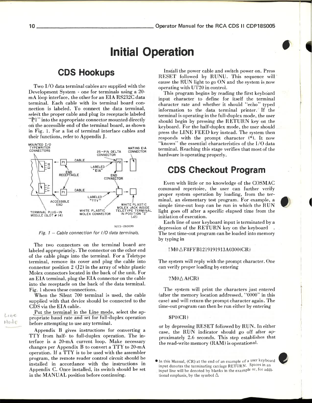
Fig. 1 - Cable connection
The
labeled
of
the
cable plugs
terminal,
connector position 2 (J2) in
Molex
an
EIA
into
the
Fig. 1 shows these connections.
When
supplied
CDS
via
Put
("
the
pr-;;pa
~
before
attempting
Appendix B gives instructions for converting a
TTY
from halfterface
changes
operation.
program,
installed in accordance with
Appendix
in the
MANUAL
System -
Each
cable
proper
1.
I/O
PLUG
(SLOT"
two connectors on
appropriately.
connectors
terminal,
receptacle on
the
with
the
te
is
per Appendix B to convert a
cable
the
appropriate
end
For
a list of
END
RECEPTACLE
-IN
14)
remove its cover
located
plug
Silent 700
that
EIA
cable.
terminal
baud
rate
to
to
a 20-mA
If a TTY
the
remote
C.
Once installed, its switch should
position before continuing.
cables
are
supplied with
one
for
terminals
the
other
for
an
EIA
RS232C
with its
To
connect the
and
of
the
terminal
to
Appendix
CAB
LE
CABLE
WHITE PLASTIC
MOLEX
The
into
the
the
the
device
in
the
and
set for full-duplex operation
use any
full-duplex operation.
current
is to
reader
terminal
data
plug
its receptacle labeled
connector
terminal
mounted
board,
interface cables
J.
25-PIN
DELTA
CONNECTOR
LABELED
"
EIA
"
END
CONNE
CTOR
LABELED
tl
TTy
ll
CONNECTOR
for
the
connector
terminal.
and
the
array
in
the
EIA
connector
back
of
terminal
should
Line
terminal.
loop.
be
used
control circuit should
TELETYPE
92CS-28210 RI
I/O
data terminals.
terminal
on
For a Teletype
plug
the
of white plastic
back
of
the
data
is used,
be
connected
mode,
Make
TTY
with
the
instructions
select
the assembler
using a 20-
board
terminal,
as shown
-0
-9
WHITE
MOLEX JACK INSIDE
IN POSITION "2"
board
the
other
cable into
the
unit.
on
the
terminal.
the
necessary
to 20-mA
Operation
RESET
the
data
con-
directly
and
MATING EIA
CONNECTOR
PLASTIC
TERMINAL
(J2)
are
end
For
cable
cable
to
the
the
ap-
The
in-
be
in
be
set
cause
operating
input
character
information
terminal
should begin by pressing the
keyboard.
press
responds with the
"knows"
terminal.
hardware
command
proper
minal,
simple time-out loop
light goes off
initiation of execution.
depression of the
The
by
The
c
an
(after the memory location
case)
time-out
or
case, the
proximately 2.6 seconds.
the
• In this Manual, (CR)
input
input
nal
tio
Install
This
the
followed
the
RUN
with
program
character
rate
is
operating
For
the
LINE
the
Reaching
is
operating
power cable
light
UT20
begins by
to defin e for itself
and
to
the
the
FEED
essential characteristics of
and
switch power on.
by R UNU.
to
go
in
control.
whether
data
in
the full-duplex mode,
half-duplex
key instead.
prompt
this stage verifies
properly.
This
ON
and
reading
it
should
terminal
RETURN
mode,
character
the
the
printer.
The
that
sequence will
system is.now
first keyboard
the
"echo"
key on
the
user should
system
(*).
the
most
CDS Checkout Program
Even
with
little
or
no
repertoire, the user
system
an
Each
line of user
test time-out
typing
!
MO
system will reply with
verify
?MOL'l
The
system will
and
$PO(CR)
by depressing
read-write
denotes
line will
emphasis,
operation
elementary
after
a specific elapsed time from
keyboard
RETURN
program
in
L'lF8FFB1219191913A0300(CR)
proper
will
program
loading by
A(CR)
print
return
can
RESET
RUN
indicator should
memory
at the e
the
terminating carriage
be
denoted
by
the symbol
knowledge of
by loading, from
test
program.
can
be
run
input
key
can
be
the
prompt
entering
the
characters
addressed,
the
prompt
then
be
run
followed
This
(RAM)
nd
by blanks in the
is
of an example
RETURN.
6.
the
COS
can
further
For
example, a •
in which
is
on
loaded
character
either by entering
by
go off after ap-
step
operational.
example
the
terminated
the
keyboard
into memory
character.
just
"0000"
again.
RUN.
establishes
of
a user
Spaces
or, for add, -
Press
terminal
typed
If the
the
user
the
then
It
now
I/ O
data
of the
MAC
verify
the
ter-
RUN
the
by
One
entered
in this
The
In
either
that
keyb
o ~rd
man
~
a
i
I
•
Page 12
••
Operating and Programming
Loading and
Outputting Programs
Programs
! M
command,
Monitor
~ection.
paper' tape via a
via the
Floppy
ill.
:the
{»18S805
supplied
fllB-duplex mode.
Following
and
magnetic cartridges:
Paper Tape Systems
To
may
commands
Ordinarily,
TI
terminal,
Disk
system.
RCA
COSMAC
Instruction
CDS
programs
are
load a
paper
be
enter
ed
manually
just
described.
are
covered in detail in
programs
TTY,
from
magnetic
or
from a floppy diskette via
The
latter is covered separately
Floppy
Manual
are designed to
the
methods
tape:
the
CDS _
This
will be loaded from
Disk
MPM-217.
used with
______
by
use of
and
tape
cassettes
System
work
paper
the
other
next
CDRCAin
tape
the
the
the
_
______
21
Type ! Maaaa
address of where the
(normally location 00001.
31
Turn
the
LINE
41
Initialize
followed by a
51
Next, type
address
read
hex bytes to
61
tape
added
The
automatically
the Section titled CDS
Development
is
from
Turn
the
is
punched,
to its
assembler
punch
Aids.
the
punch
mode.
the
RETURN
the
starting
memory,
be
punched.
punch
end.
reloadable
__________
6 where
OFF
CDS
?Maaaa
and
ON
some
and
data
and
with a
(CRI.
6count,
address of
count
and
press
more
editor
tape
Resident
11
aaaa
is
the hex
is to be reloaded
put
the
TTY
in
RESET,
is
nulls should
RUNU,
where the
data
the
number
CR.
After
programs
as
described in
Software
to be
of
the
be
1
paper-tape loading by pressing the
in
re-initialize the system
HESET,
the loaded
issue a
det
ning.
•
U Press
21
Make
installed switch is in the
31
is
41
the tape recorder.
51
another
61
If
preferred , typing
stead of
UT20
ected, stop
To
11
position
ON,
Pl.
RESET,
Press
the
RETURN
sure it is in
UT20
will
ready
to
accept
Position the tape in
When loading
*.
Start
the
program
CR
at
step 2.
RUN
U,
and
program.
monitors
'!
if a
punch reloadable tape:
With
the
format
and
the
tape
and
make a header
followed
return
commands.
is
can
In
after
CR
program
error
reload
TTY
in
the
by
RUN
U.
key
(C-R)
on the
TTY.
the
LINE
MANUAL
the symbol * indicating it
the
complete,
by typing$UO(CR).
be
this case, the user should
before
is detected.
the
in
punch,
Mode
and
the
position.
header
loading by pressing
being loaded
tape
the
of nulls (control-shift-
and
tum
UT20
will issue
suppressed
LINE
FEED
attempting
and
If
an
from the begin-
LOCAL
tum
the
during
key
to
start
will
error
mode,
punch
.
on
is
Magnetic Tape Systems
To
load a
1) Press
2)
3)
LOAD/FF
Make
PLAYBACK
41
another
$UO(CR).
Typing
the
printer
e
rror
has
reloaded.
To
11
RECORD
2)
address of where
(normally location 00001 .
3) Switch
mode
RUN
magnetic
RESET,
UT20
will
Mount
sure
When loading is completed,
* .
during
OFF.
been detected
record reload able tape:
With
the
Type
and
U,
and
return
the
cassette.
to
advance
the
mode.
Start
load
If
a ?
terminal in
mode,
!Maaaa
to
the
initialize
CR.
tape:
RUN
U,
then
the
symbol
Rewind
to
drive
is
in
the
program
can be
suppressed
is
typed
during
and
the
mount a blank
6 where
data
is to
LINE
the
and
CDS
CR.
*.
it
and
the
first record.
the
LINE
UT20
by typing
by
loading,
tape should
the
LOCAL
cartridge.
aaaa
is
be
PLAYBACK
with a
press
and
will issue
turning
an
be
and
the
hex
reloaded
RESET,
Page 13
12
_____________
4)
Type
the
starting
memory
to
be
recorded.
?Maaaa
address
and
count
6count,
of
the
is
the
where the
data
to be
number
____
address
read
of hex bytes
is
from
Operator Manual
5)
Tum
press
CR.
UT20
will issue
For'
another
supplied
"Deduce"
for
the RCA CDS II CDP18S005
the
Record
After
system
game,
Control
the
another
checkout
refer
data
*.
to
switch
has
been
program
Appendix
ON
output,
using
H.
,
and
the
Utility
The
CDP18S005
includes a
performs
terminal
generating
memory
program
detail
plus
In
user
of
his
U begins execution of
RUN
or a CR
installation. A
operation,
establishing
calculate
terminal.
wide
Monitor
commonly
interface,
reload
locations,
at
a given location.
the
?M
others
not yet discussed.
general,
has
two choices: pressing
program
U,
the
(carriage
an
the
the
Thus,
variations
program,
providing a means
able
and! M commands
after
the
at
location 0000, while pressing
user
next
return)
CR
LF,
need
timing
a single
in clock
Introduction
Monitor
Commands
COSMAC
required
tape,
and
system
UT20
presses
initiates
HALF
to
echo,
parameters
speed
Development
known
functions
allows
The
(at
key,
UT20
program
or
as
of
giving _ access
the
following
already
has
been
RUN
begins execution
8000). After pressing
either a LF
depending
FULL
DUPLEX.
uses
necessary
can
terminal
System
UT20,
of
running
reading
user
to
explains
mentioned,
RESET,
(line feed)
upon
DUPLEX
Besides
this
input
to
run
operate
speed.
UT20
which
the
and
to
all
start
in
the
RUN
his
to
the
with
to
the
Software
every 16
semicolons.
to
specify
implied,
entered,
bytes
than
used.
simply by
~ypedffse~uelnce
IS,
typed
example:
would
02F5.
paper
previously
bytes,
the
if
only
to
be
four
This
e ectlVe y, . t e
is
not
?M2F5(CR)
result
When
tape,
with
the
The
user
may
enter
beginning
necessary).
the
last
typed
out
digits
are
feature allows
continuing
OWoi2th4)theIfcorhrect
specified, one byte is
in the
the
user
he
described.
location (leading zeroes
If
more
four
should
entered,
the
the
typeout
wants
requests a memory
previous lines
are
be
only
correction of a
type
num
of
the
to
any
number
than
used.
in
hex.
the
and
,terminating
4-dbigit
er
one
punch
ending
of digits
four
digits
The
number
Again, if
last
four
mistake
vfalbues
(2300b24
0 ytes
assumed.
byte
at
location
a reloadable
type-out
in
are
are
of
more
are
the
to
For
as
..,
~
e
1
When
UT20
out
an
asterisk (*)
?M
Commands
To
interrogate
as
?M2F53(CR)
UT20
responds
memory
printed
begins
(4-digit) blocks.
beginning
out
as
with
the
is
ready
as a prompt
at
two
hex
address,
When
to
accept a command,
character.
memory,
by
location
digits
necessary,
type a command
printing
02F5:
each.
and
data
out
Each
is
new
the
contents
three
line of
grouped
lines
it
bytes
output
in
are
types
such
of
are
2-byte
begun
!M
Commands
In
general,
means
of a
!MI2F
This
each)
into
memory
again,
four
each
number
error
necessary
the
digits
two
hex
of digits,
message
to
data
is
command
command
starting
entered.
digits
re-enter
such
434F534D4143(CR)
enters
beginning
location is
Data
is
are
typed.
the
last
('?')
is
typed
the
last
entered
as
entered
digit is ignored,
out.
byte.
into
six
bytes
at
location
determined
into
If
the
user
It
is therefore only
(two hex digits
memory
memory,
012F. Once
by
the
last
after
types
an
odd
and
by
.,
.,
the
Page 14
•
•
Operating and Programming the CDS
The
! M
command
facilitate memory loading.
be extended from line to line
just
before
the
normal
LF
(carriage return-line feed) keys before beginning a
new line.)
: enters
Between successive hex pairs while
entered,
land
arrangement
readability), nulls (generated by
or
by a time-share system to give
return), etc.
string of
land a CR).
data
beginning address.
an
option provides the mechanism
tape previously
command.
puts discussed above.)
characters
to be inserted in
command.
contiguous memory
$U
execution.
For
example,
!M23
56789ABC,(CR) (LF)
DEFOI23456,(CR)
3047(CR)
11
successive bytes beginning
any
non-hex
semicolon, as will
permits
As
a second optional form of
input
data
can
The
utility
to follow
! M
The
on
command,
punched
(Recall
utility
following !
the
The
the next line,
The
but
the
semicolon
areas
Commands
The
$U
command
For
example,
$U6C(CR)
provides two options
First,
by
CR.
(In this case press
(LF)
character
be
discussed) is ignored.
arbitrary
be
terminated
program
but
line
must
with
the
f~r
out
as a result of
format
program
M,
tape
of multiline
ignores all non-hex
allowing
without
feature
to
be
loaded.
is used to
_________
a string of
typing in a
at
location 0023.
data
except the
LF's,
the
utility
the
carriage time to
data
by a semicolon
then
expects
preceded by a new
have
the
! M omitted.
reading
CR,
LF,
disturbing
allows non-
start
that
data
can
comma
the
CR-
is being
comma
This
spaces (for
program
entry,
more
format
in a
and
of
This
paper
the
?M
?M
out-
nulls
the
! M
program
__
$P
Commands
The
$P
~or
example:
$P6C(CR)
would also
with
P=X=O
floppy disk interfaces
a convenience for
I/O
commands
peri pherals.
If
no
starts from location 0000.
to
pushing
control panel.
digits' address rule.
For
a
"Two-Level
in the
$L
floppy disk.
causes
asking for the
file to be loaded.
program,
System
217.
command
after the
further
next
Section.
Commands
The
$L
$L
UT20
READ?
refer to the
II
If
a floppy disk system is
is
READ?
_____________
command
start
except,
address
the
RESET
This
I/O"
command
Typing
to type
unit
CDP18S805
accidentally activated, simply do a
is similar to the $U
program
the
normally associated with these
details of this
under
For
interrogation.
execution
in
this case,
may
be disabled.
user so
is specified,
command
and
that
his
program
The
function
then
RUN P buttons
also obeys
command,
Input/Output
is used in systems having a
track
number
a discussion of the disk loader
RCA
COSMAC
Instruction
not
UT20
command.
at
location 006C
the
temiinal
This
program
is
equivalent
the
Interfacing
of
the
Floppy
Manual
installed
will type
13
and
feature is
can use
execution
on
the
'last-4-
refer to
diskette
Disk
MPM-
and
this
CR
1
1
•
starts
P = X
interface
tive. Consequently, the user
I/O
further
floppy disk interface, see the material
Description
Section.
to "Two-Level
facing
specified, execution will
more
will
program
=0.
This
and
floppy disk interface (if installed) ac-
commands
discussion of
For
in the
If
only
than 4 address
be
used.
associated with these interfaces.
and
further
next
$U
execution
command
the
Signal
details on
110"
under
Section.
(CR) is
digits
at
location 006C with
will leave
program
terminal
Mnemonics
the
Input/Output
typed
start
are
should
interface
$U
command,
with
at
location 0000.
typed,
only the
the
on
in the
no
terminal
not
use
For
a
and
the
Module
next
refer
Inter-
address
If
last
and
?R
one of
'R'
address
R4.1 are altered,
registers
activated.
4
examining most
poses.
DRIVE
issue an
NOT
*,
waiting for
Commands
When
UT20
is activated (via
the
first things
registers of
the
8COO
for 32 bytes. Registers
are
preserved
This
feature provides a means of
CPU
ON
another
it
Qoes
CPU
in its
but
the
at
the
registers for debugging
command.
RESET,
is save 13-112 of
RAM
stack
states of the remaining
time
when
RO,
RUN
the
located
RI,
UT20
U),
16
at
and
was
pur-
Page 15
14
_________________
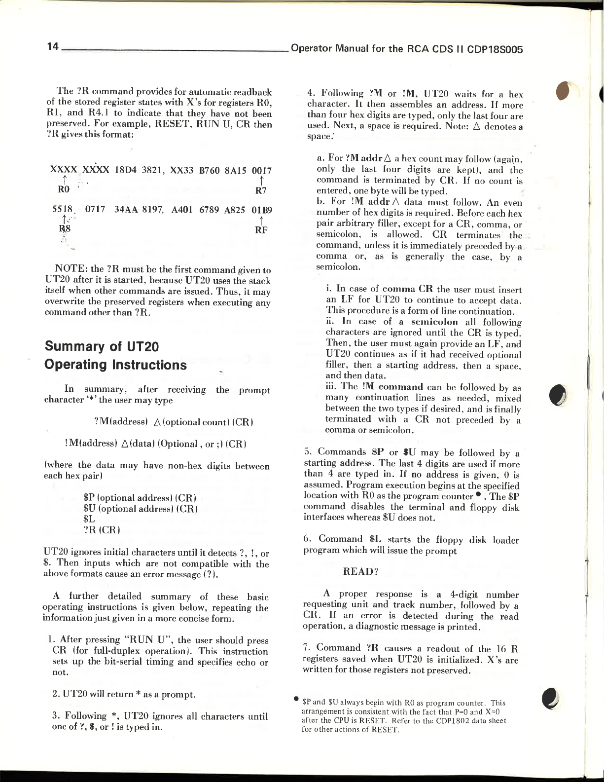
The
?R
command
of
the
stored register states with
RI,
and
R4.I
preserved.
?R
gives this format:
XXXX XXXX
t t
RO
5518
For
0717 34AA
provides for
to
indicate
example,
18D4 3821, XX33 B760 8A15 0017
RESET,
8197,
automatic
X's
for registers
that
they
have
RUN
U,
A401 6789 A825 01B9
t c':
1\8
NOTE:
UT20
itself
overwrite
command
after
when
the
?R
must
be
the
first
command
it
is
started,
other
commands
the
preserved registers when executing any
other
than
because
?R.
are
UT20
issued.
uses
Thus,
Summary of UT20
Operating Instructions
In
summary,
character
'*'
the
?M(addressl
!M(addressl
(where
the
data
each hex pair)
$P
(optional
$U (optional address)
$L
'?R(CR)
UT20
ignores initial
$,
Then
inputs which are
above formats cause
after
user
may
f.,(datal
may
address I (CRI
characters
an
receiving
the
type
f.,
(optional count) (CRI
(Optional,
have
non-hex digits between
or;)
(CRI
until
it
detects?,
not
compatible with
error
message (?
I.
readback
RO,
not
been
CR
then
R7
RF
given to
the
stack
it
may
prompt
(CR)
!,
t
or
the
0perator
Manual
4. Following
character.
than
four hex digits
used.
Next,
space:
a.
For
the
only
command
entered,
b.
For
number
pair
arbitrary
semicolon.
command,
comma
semicolon.
i.
In
an
LF
This
ii.
In
characters
Then,
UT20
filler,
and
then
iii.
The
many
between
terminated
comma
5.
Commands
starting
than
address.
4 are
assumed.
location with
command
interfaces whereas
6.
Command
program
which will issue the
for
the RCA CDS II CDP18S005
'~M
or
!M,
UT20
It
then
assembles
are
'!M
a space
addr
last
is
is
f.,
four digits
terminated
one byte will
!M
addr
f.,
of hex digits is
required.
a hex
data
an
typed, only the
Note:
count
may
are
by
CR.
be
typed.
must
required,
filler, except for a
is
unless
allowed.
it
is
CR
immediately preceded by a
or, as is generally
case of
for
comma
UT20
CR
to
continue
the
procedure is a form of line
case of a
are
the
user
continues as if it
then a starting
semicolon
ignored
must
again provide
until
had
address, then a space,
data.
!M
command
continuation
the
two types
with a
or
semicolon.
$P
The
typed
in.
Program
RO
as
disables
$U
$L
or
execution begins
the
the
starts
can
lines as needed, mixed
if
desired,
CR
not
$U
may
be
last 4 digits are used
If
no
address
program
counter· . The
terminal
does
not.
the
floppy disk loader
prompt
READ?
waits for a hex
address.
If
last
four
f.,
denotes a
more
are
follow (aga\n,
kept),
If
no
and
count
the
is
follow. An even
Before each hex
CR.
comma,
terminates
the
case, by a
user
must
to
accept
or
the
insert
data.
continuation.
all following
the
CR
is
typed.
an
LF,
and
received optional
be followed by as
and
is
finally
preceded
followed
is
at
the
by
by
if
more
given, 0
specified
is
$P
and
floppy disk
a
a
A
further
operating
instructions is given below,
information
1.
After pressing
CR
(for full-duplex
sets
up
not.
2.
UT20
3. Following
one of '!,
detailed
just
given in a more concise form.
"RUN
summary
U",
the
operation
the bit-serial
will
return
*,
$,
or
! is
* as a
UT20
typed
timing
and
prompt.
ignores all characters
in.
of these
basic
repeating
user should press
I,
This
instruction
specifies echo
the
or
until
A
proper
requesting
CR.
If
an
operation, a diagnostic message is
7.
Command
registers saved when
written
• $P
arrangement is consistent
after
for
for those registers
and
$U
always begin with
the CPU is RESET. Refer to the CDP1802 data sheet
other
actions
response is a 4-digit
unit
and
track
number,
error
is detected
?R causes a
UT20
not
RO
as program
with
the fact that
of
RESET.
during
printed.
readout
is initialized.
preserved.
number
followed
the
of the 16 R
X's
counter.
P=O
and
This
X=O
by
read
are
a
Page 16
•
•
•
Operating and Programming
H.
When
a
!M,
·!M
or
!'R
and
completed,
9. When
and
returns
data
is
entered
digitsl, all
last hex digit.
tnl
'e in
the
address
mand.
:corrected by
fectively, 0235. A
typing in any illegal
·-
'!M
the
example, a period.
For
or
between
user
error
UT20
types
UT20
detects
the
carriage.
data
will
Note
address
without
example, a mistaken
continuing.
input
should
bad
(by
typing
have
that
the
field allows
retyping
bad
command
character
hex
type any
If
data
Terminal Interfacing
ASCII Coding
The
CDS
is designed
terminal
current
interface.
the information
to
minals as a serial
originating
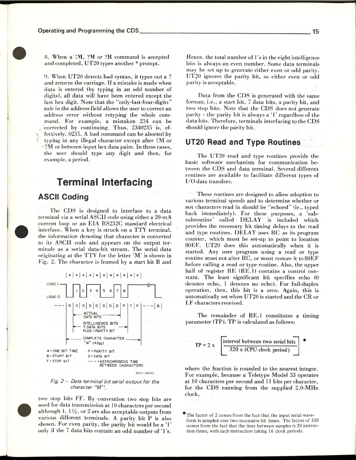
Fig. 2.
two stop bits
used for
although
various different
shown.
only
via a serial
loop
or
an
When
its
ASCII
LOGIC
.... = ONE
B = START
F =
STOP
Fig.
if
the 7 data
code
at
the
The
character
I
BFI
BIT TIME P = PARITY BIT
BIT
BIT
2 -
Data
character
FF.
data
transmission
1, I
liz,
For
even
ASCII
EIA
a key is
denoting
and
data-bit
TTY
DI
DI
ACTUAL
-
DATA
INTELLIGENCE BITS
DATA
7
PLUS I PARITY BIT
COMPLETE CHARACTER
"M"
D'
---
terminal
By convention two stop bits
or 2 are
terminals. A parity
parity,
bits
code
RS232C
struck
that
appears
stream.
for the letter
is
framed
DI
~I
DI
BITS
BITS
(4DI6)
DATA
BIT
=ASYNCHRONOUS TIME
BETWEEN CHARACTERS
bit
"M"
.
at
10
also acceptable
the
parity
contain
the
CDS
________________________
command
another * prompt.
syntax, it types
a
mistake
in
been
"only-Iast-four-digits"
the
Thus,
pairs.
digit
to
interface to a
using
on a
character
On
by a start
D~
serial
characters
an
odd
is accepted
is
made
an
odd
number
entered
can
except after
standard
output
bit
except
user to
correct
the
whole com-
234
2340235 is, ef-
be
aborted
In
these cases,
and
then,
either a 20-mA
electrical
TTY
terminal,
is
converted
the
output
The
serial
'M'
is shown in
bit
---I
FI
F
92CS
-28100
for the
per
outputs
bit P is
would
number
out
when
can
!M
Band
B 1
second
from
be a 'I'
of '1
a ?
of
the
an
be
by
or
for
data
ter-
data
are
also
'so
Hence,
bits
may be set
UT?O ignores the
rarity
format;
two
parity - the parity
data
should ignore
the total
is
always
is acceptable.
Data
i.e., a start
stop
bits. Therefore, terminals interfacing to the
up
from
bits.
number
an
to
the
Note
the
even
number.
generate
parity
CDS
bit, 7 data
that
bit
is always a
parity
bit.
of 1
's
in the eight intelligence
Some
either
even
bit, so
is
the
either
generated
bits, a parity bit,
CDS
does
'I'
UT20 Read and Type Routines
The
UT20
read
and
type
routines
basic software
tween
the
routines
110
data
These
various
not
characters
back
immediately
subroutine'
provides
'
and
type routines.
c
ounter,
80EF.
started.
routine
before calling a
half of register
stant.
denotes echo, 1
operation,
automatically
LF
parameter
where
For
at
for
clock,
-The
form is sampled over
comes from the fact
tion
must
The
characters
The
TP=2
the
example, because a
10
characters
the
factor
times, with each instruction taking 16 clock periods.
are available to facilitate different types of
transfers.
terminal
the
UT20
Any user
CDS
of
mechanism
CDS
and
data
routines
which
then,
remainder
(TPI.
x
fraction is
2 comes from the fact
are
speeds
read
in
I.
For
called
necessary
not
least significant
set when
received.
DELA
DELAY
must
does this
program
alter
read
or
RE
(RE.I)
denotes
this
of
TP
is calculated
.nterval
320 x
~
rounded
per
second
running
two
successive bit times. The factor
that
the time between samples
for
terminal.
designed
and
to
should
be set-up to
RC,
between two serial
be
these
Y is included which
bit
timing delays to
uses
automatically
using a read
or
must
type
routine.
contains
no
echol.
bit
is a zero. Again, this is
UT20
is
RE.l
(CPU
clock period)
Teletype
and
from
the
that
communication
Several different
to
allow adoption to
determine
"echoed"
purposes,
RC
point
restore it to
bit
specifies echo (0
started
constitutes a timing
as
follows:
to
the
Model
II
bits
supplied
the
data
terminals
or
odd
parity.
even or
with
the
not
generate
regardless of
provide
whether
(ie., typed
a 'sub-
the
as its
program
to location
when it is
or
80EF
Also,
the
upper
a control con-
For
full-duplex
and
the
CR
bit~
•
nearest
input
integer.
33 operates
per
character,
2.0-MHz
serial wave-
is
20 instruc-
of
15
odd
same
and
the
CDS
the
be-
or
read
type
or
320
Page 17
16
_________________
0perator
Manual
for
the
RCA CDS II CDP18S005
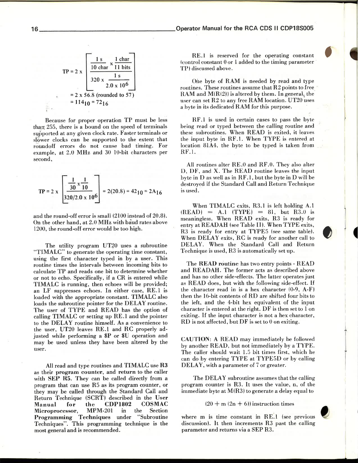
1 s 1 char
--
TP
=2
10
x
320 x
= 2 x 56.8 (rounded to
114
=
Because for
tha.o:
255,
there
s}:\pported
slower clocks
roundoff
example,
second,
TP
and
On
the
1200, the round-off
"TIMALC"
using the first
routine times
calculate
or
not
TIMALC
an
loaded
loads
The
calling
to
the
the user,
justed
may
user.
as
their
with
program
they
Return
Manual
Microprocessor,
Programming
Techniques".
most
at
any
can
errors
at
2.0
J 1 J
= 2 x = 2(20.8) = 4210 = 2A16
the
The
LF
the
user
be used unless
All
SEP
may
general
3o
320/2.0
~
round-off
other
hand,
utility
to
generate
character
the
TP
and
to echo. Specifically, if a
is
running,
suppresses echoes.
with
the
subroutine
of
TYPE
TIMALC
DELAY
UT20
while
performing a $P
read
and
program
R5.
that
can
be
called
Technique
for
This
and
=
10
proper
is a
bound
given clock
be
supported
do
not
MHz
x
lo
x 10
error
is small (2100
at
2.0
error
program
intervals
reads
then
appropriate
pointer
and
or
setting
routine
leaves
they
type
routines
counter,
They
can
use
R5
through
(SCRTI
the
MPM-201
Techniques
programming
is
recommended.
x---
char
11
bits
1 s
the
6
57)
TP
speed
Faster
to
the
bad
characters
2.0 x 10
72
16
operation
on
rate.
cause
and
30 lO-bit
6
instead
MHz
with
baud
would be too high.
UT20
the
typed
one
READ
himself. As a convenience
RE.l
have been altered
be
as
uses a
operating
between
bit
to
echoes will be provided;
In
constant.
for
up
RE.l
and
or
and
and
called directly
its
the
described
CDP1802
time
in
by
incoming bits to
determine
CR
is entered while
either
TIMALC
the
DELAY
has
and
RC
$U
TIMALC
return
program
Standard
in
under
technique
must
be
of
terminals
terminals
extent
timing.
of 20.81.
rates
above
subroutine
constant,
a user.
whether
case,
RE.l
routine.
the
option of
the
pointer
properly ad-
operation
by
use
to
the
caller
from
counter,
Call
in
the
COS
MAC
the
Section
"Subroutine
is
less
or
that
For
per
This
is
also
to
and
the
R3
or
and
User
the
RE.l
(control
'1'P
I discussed above.
One byte of
routines.
RAM
and
user
can
a
byte
in its
R
F.I
being
read
these subroutines.
the
input
location 81A4,
RF.l.
All rontines alter
D.
DF,
byte
in 0
destroyed if
is
used.
When
(READl
meaningless. When
at
entry
R3
is
ready
When
DELAY
D E LAY. When
Technique
The
READ
and
READAH.
and
has
as
READ
the
character
then
the
the left.
character
exiting.
RD
is
not
CAUTION: A READ
by
another
The
caller should
can
do by entering
DELAY,
a
The
program
immediate
where m is
discussion
parameter
is
reserved for
constant 0 or 1 added
RAM
is
needed
These
routines assume
M(R(211
set
R2
dedicated
is
or
byte in
and
as
the
TIMALC
=
READAH
is used,
no
other
does,
I6-bit
and
is entered
If
the
affected,
READ,
with a parameter
DELAY
counter
byte
(20 + m (2n +
I.
and
is
altered
to
any
free
RAM
used
in
certain
typed between
When
RF
.1. When
the
byte
RE.O
X.
The
READ
well
as
in
RF.l.
Standard
exits,
A.I
(TYPEI
READ
(see
Table
for
entry
at
exits,
RC
the
Standard
R3
is
routine
but
read
contents
the
input
at
time
It
then
returns
has two
The
former acts as described above
side-effects.
with
in is a hex
of
4-bit
at the right.
character
but
DF
may
but
not
wait
TYPE
subroutine
is
R3.
M(R31 to
constant
increments
via a
RAM
READ
to
and
Call
TYPE5
is
automatically
the
RD
hex
is
immediately
1.5
at
of 7
It
611
the
operating
to
the
timing
by
that
R2
by
them.
location.
for
this
purpose.
cases
to
the
calling routine
is exited,
TYPE
be
typed
RF.O.
routine
but
R3.1
leaves
the
byte
and
Return
is left holding
= 81,
exits,
R3
III.
When
(see same tablel. a
ready
for
Call
entry
The
latter
following side-effect.
character
are shifted four bits to
equivalent
DF
is
is
not
a hex
set
to
0 on exiting.
immediately
bit
times
TYPE5D
or
greater.
assumes
uses
the
value,
generate
instruction
in RE:I (see previous
SEP
R3
R3.
a delay
past
constant
parameter
read
and
points
to
In
general~
UT20
pass the byte
it
leaves
is
entered
is
taken
from
They
also
alter
the
input
in
D will be
Technique
but
R3.0
is
ready
TYPE
another
and
set
points -
operates
then
first, which he
or
that
times
exits,
call
Return
up.
READ
(0-9, A-FI
of
the
input
set to 1 on
character,
be followed
by a TYPE.
by calling
the calling
n,
of
equal
the
calling
type
free
the
uses
and
at
A.I
is
for
to
just
If
the
to
~
1
Page 18
•
Operating and Programming the
The
TYPE
points.
to fetch the
TYPE5
TYPE6
TYPE5D
before going to
to
process to completion before typing.
eritry which results in
form as two hex digits.
a,
Three
types from M(R51
types from M(R61
is
let"
an
ASCII
hex digit (0-9, A-Fl
routine
of
them
character
an
entry which provides a lo5-bit delay
TYPE5.
immediately preceding echoed
has
simply specify different places
from:
TYPE
and
The
RF.l
Each
CDS
five different
increments
and
purpose
being typed
4-bit half
and
. out.
Notice
facilitate
TYPE
TYPE5.
characters
restriction
TYPE5D
that
repeated
routines
In
order
following a
mentioned
first.
the
READ
calls on
are
designed for repeated calls
to
output
using
routines
READAH,
a string of variable
READ,
earlier.
an
immediate
it
is
given the
most
________________________
types from
R5,
increments
of this delay is
TYPE2
out
is
converted to
separately
are
designed to
while
logical to call
"punctuation"
entry
RF.l,
and
R6.
READ
is
an
in hex
typed
the
to
data
timing
byte (i.e.,
required initial delay
repeated
data
characters picked
calls on
This
procedure
rate.
Another routine,
output
character
character
encoded in
the
program
user via a
typed
includes a delay
called
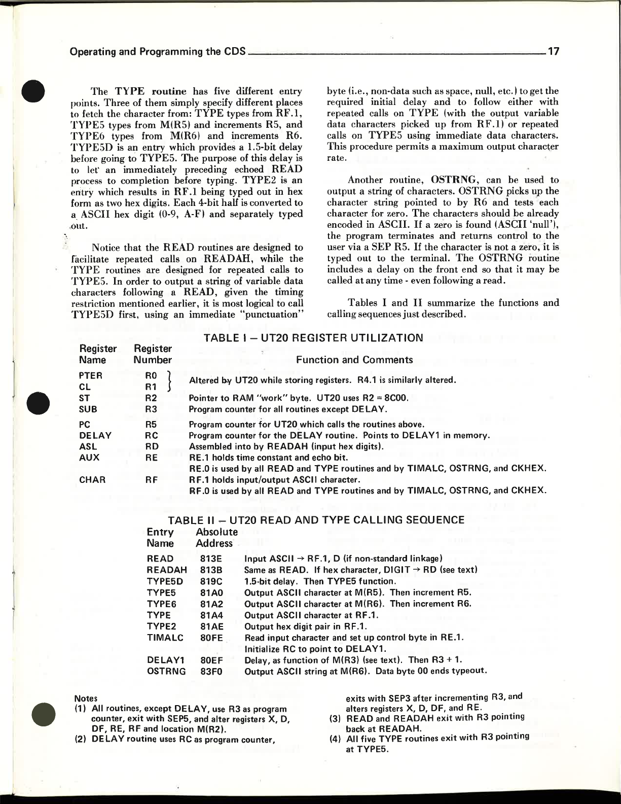
Tables I and
calling sequences
non-data
calls on
TYPE5
a string of characters.
string
for zero.
ASCII.
SEP
out
to
at
any
such as space, null, etc. I to
and
TYPE
up
using
immediate
permits a maximum
OSTRNG,
pointed
The
characters
If
a zero is found
terminates
R5.
the
on
time - even following a
just
and
If
the
character
terminal.
the
front
II
summarize
described.
to follow either with
(with
the
output
from
OSTRNG
to
by
returns
The
end
RF.Il
R6
or
data
characters.
output
can
be
picks
and
tests each
should
OSTRNG
so
the
(ASCII
control to
is
not
that
read.
functions
be
a zero,
repeated
character
it
17
get
the
variable
used
to
up
the
already
'null'l,
the
it
is
routine
may
be
and
•
Register
Name
PTER
CL
ST
SUB
PC
DELAY
ASL
AUX
CHAR
Register
Number
RO
R1
R2
R3
R5
RC
RD
RE
RF
J
Alt.ered
Pointer
Program
Program
Program
Assembled
RE.1 holds
RE,O
R F.1 holds
RF.O
TABLE
Entry
Absolute
Name Address
READ
READAH
TYPE5D
TYPE5 81AO
TYPES
TYPE
TYPE2
TIMALC
DELAY1
OSTRNG
813E
813B
819C
81A2
81A4
a1AE
80FE
80EF
83FO
TABLE 1-UT20 REGISTER
Function
b-y
UT20 while storing registers. R4.1
to
RAM
"work"
is
is
used
used
counter
counter
counter
for
for
for
into
by
time
constant
by
all READ
input/output
by
all READ
II - UT20 READ
Input
Same
1.5-bit delay. Then TYP
Output
Output
Output
Output
Read
Initialize RC
Delay,
Output
byte.
UT20
all
routines
UT20
the
DELAY
READAH
ASCII ~
as
READ.
ASCII
ASCII
ASCII
hex digit pair in R F .1.
input
as
function
ASCII string
except
which calls
routine.
(input
and
echo
bit.
and
TYPE routines and
ASCII
character.
and
TYPE routines and
AND
TYPE
RF.1,
0 (if non-standard linkage)
If
hex
character
character
character
character
to
point
of
and set
to
M(R3) (see
at
hex
character,
M(RS). Data
UTILIZATION
and
Comments
is
similarly
uses R2 =
DE
the
8COO.
LA
Y.
routines above.
Points
to
digits).
by
by
CALLING
DIGIT ~ RD (see
E5
function.
at
M(R5). Then
at
M(RS). Then
at
RF .1.
up
control
DELAY1.
text).
byte
altered.
DELAY1 in
TIMALC,
TIMALC,
OSTRNG,
OSTRNG,
SEQUENCE
increment
increment
byte
in
RE.1.
Then R3 + 1.
00
ends
typeout
memory.
text)
R5.
RS.
.
and CKHEX.
and
CKHEX.
•
Notes
(1) All routines,
counter,
OF, RE, RF
(2) DELAY
exit
routine
except
and
DE LA
Y,
with
SEP5, and
location M(R2).
uses RC as program
use R3
alter
as
program
registers
counter,
X,D,
exits with
alters registers
(3) READ and READAH
back
(4) All five TYPE
at
TYPE5.
SEP3
at
READAH.
after
X,D,
routines
incrementing
OF,
and
RE.
exit
with R3 pointing
exit
with
R3, and
R3 pointing
Page 19
18
__________________
Operator Manual
for
the
RCA
CDS II CDP18S005
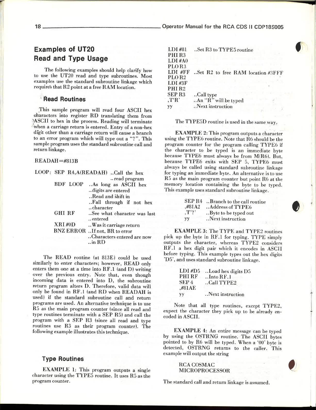
Examples of UT20
Read and Type Usage
The
following examples should help clarify how
to use the
examples use
require's
: Read Routines
.This sample
characters
~SCII
-<
when a carriage
digit
to
an
sample
return
READAH=#813B
LOOP:
The
similarly to
enters
over the previous entry.
incoming
return
only be found in
used) if the
programs
R5 as the main
type routines
program
routines use
following example illustrates this technique.
Type Routines
c
haracter
program
UT20
read
the
standard
that
R2
point
program
into register
to hex in the process.
return
other
than
a carriage
error
program
program
linkage.
SEP
BDF
GHI
XRI
BNZ
READ
enter
them
one
data
program
are
used. An alternative technique is to use
terminate
with a
EXAMPLE
using the
counter.
which will type
uses
the
R4,A(READAH)
LOOP
RF
HOD
ERROR
routine
characters;
at
a time into
is
entered
alters
RF.I
standard
program
SEP
R3
as their
1:
This
TYPES
and
type subroutines.
subroutine
at
a free
RAM
will
read
RD
translating
Reading
is entered.
return
standard
..
As
long as
.. digits are entered
..
Read
.. Fall
..
character
.. See
what
.. entered
..
Was
it
..
If
not,
..
Characters
.. in
RD
(at 813E) could be used
however,
RF.I
Note
into
D.
Therefore,
(and
RD
subroutine call
counter
with a
R3 (since
SEP
program
program
routine.
linkage which
location.
four
will
Entry
will cause a
out
subroutine call
.. Call the hex
read
..
ASCII
and
shift in
through
character
carriage
BR
to error
entered
(and
that,
D,
the subroutine
valid
when
(since all
RS)
all
read
counter).
outputs
It
uses RS as
Most
ASCII
them
of a non-hex
a
program
if
return
READ
even
READAH
and
and
hex
from
terminate
branch
"?".
This
and
hex
not
hex
was last
are
now
only
D)
writing
though
data
will
return
read
and
call
the
and
type
The
a single
the
is
LDI
PHIR3
LDI
PLOR3
LDI
PLOR2
LDI
PHIR2
SEPR3
,T'R'
yy
The
EXAMPLE
using the
program
character
the
because
because
always be called using
for typing
RS as the main
memory location
This
example uses
EXAMPLE
up
pick
outputs the
RF.I
before typing.
'DS',
and
Note
expect the
coded in
EXAMPLE
by using
pointed
detected,
example will
The
standard
.. Set R3 to
#81
#AO
#FF
#3F
TYPESD
TYPE6
counter for
TYPE6
TYPE6
an
SEP
,#8IA2 .. Address of
,
T'?'
yy .. Next instruction
the
a hex digit
uses
LDI
PHIRF
SEP4
,
#8IAE
yy
that
character
ASCII.
the
to
by R6 will
OSTRNG
RCACOSMAC
MICROPROCESSOR
R2
.. Set
.. Call type
.. An
"R"
..
Next
instruction
routine is used in the
2:
This
routine.
to
be
must
exits with
immediate
program
containing
standard
R4
..
Branch
.. Byte to be typed
3:
The
byte in
character,
#DS
output
call
RF.I
pair
This
example types
standard
..
Load
..
IntoRF.1
.. Call
..
Next
all type routines, except
4: An entire message
OSTRNG
the
and
TYPES
to free
will be
program
the
typed is
always be from
standard
byte. An alternative is to use
TYPE
which
subroutine
TYPE2
they
be
returns
string
return
routine
RAM
location
typed
same
outputs a chara
Note
that
R6
should be the
program
counter
subroutine
to the call routine
for typing.
whereas
hex digits DS
instruction
pick
routine.
typed.
calling
an
immediate byte
M(R6).
SEP
S,
TYPE6
subroutine linkage
but
point
the byte to be typed.
linkage .
TYPE6
out
and
TYPE2
TYPE
TYPE2
it
encodes in
out
the hex digits
linkage.
up
to be already en-
can
The
ASCII
When
a '00 ' byte
to the caller.
linkage
is
assumed.
TYPE6
R6
routines
considers
TYPE2,
be
#:~FFF
way,
cter
if
But,
must
at
the
simply
ASCII
typed
bytes
is
This
I
I
r
Page 20
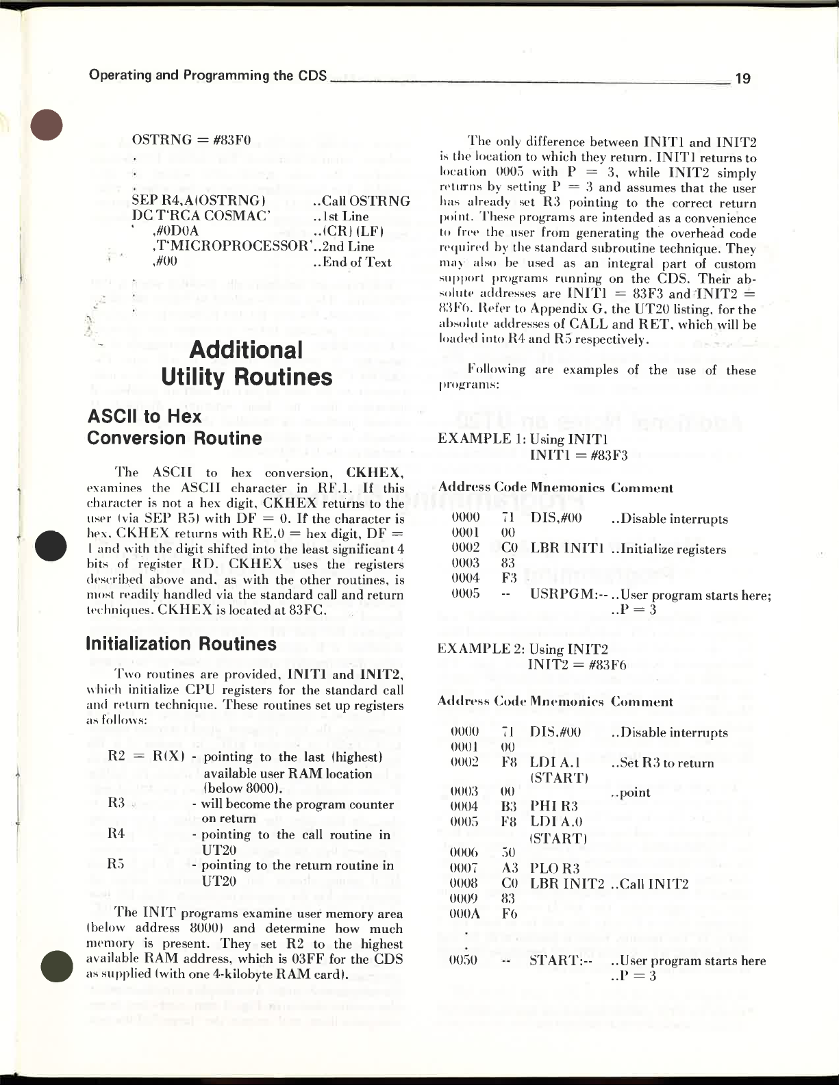
Operating and Programming
the
CDS
______
_
________________
19
•
•
.
,:'
"
OSTRNG
SEP
DC
,#ODOA
,T'MICROPROCESSOR'
,#00
= #83FO
R4,A(OSTRNG
T'RCA
COSMAC'
Additional
Utility Routines
ASCII to Hex
Conversion Routine
The
ASCII
examines the
chanl(;ter is
IIser Ivia
IIPx.
CKHEX
I
and
bits of
dt's('rihed above
most ft'adily
lI'Chniques.
not
SEP
with the
~egister
handled
CKHEX
to hex conversion,
ASCII
a hex digit,
R:)I with
returns
digit
character
OF = O.
with RE.O = hex digit,
shifted into
RD.
CKHEX
and.
as with
via the
is located
I .. Call
.. 1st Line
.. (CRI (LFI
..
2nd
..
End
in
RF.l.
CKHEX
the
the
standard
at
returns
If
the
least significant 4
uses the registers
other
call
83FC.
OSTRNG
Line
of
Text
CKHEX,
If
this
to
the
character
OF
routines, is
and
return
is
=
The
only difference between
is
the lo(;ation to which they
location 000:) with P
rptllTns by sf'tting P
has already set
point.
These
programs
to !'n't' the IIser from
n'<Jllin'd by the
llW)
also be used as
support
,;olllte addresses
B:W(I. Hefer to Appendix
absollltt' addresses of
loaded into R4
prol-(rams:
EXAMPLE
Address
0000
0001
0002
0003
0004
00U5
programs
Following
1:
Code
71
00
CO
83
F:~
=
R:1
pointing to the correct
generating
standard
running
are
INITl
CALL
and
R:) respectively.
are
examples
Using
INITl
INITl
Mnemonics
DIS,#OO
LBR
USRPGM:--
= #83F3
INITI
INITI
return.
=
:1,
while
:1
and
assumes
are
intended
the overhead code
subroutine
an
integral
on
the
=
83F3
G,
the
UT20
and
RET,
of
the
Comment
..
Disable
.. Initialize registers
.. User
program
.. P = 3
and
INIT2
INITI
as a convenience
technique.
CDS.
returns
INIT2
part
and
listing, for
use of these
interrupts
simply
that
the user
return
of custom
Their
-INIT2
which will
starts
They
ab-
~
the
be
here;
to
Initialization Routines
\\ hil'h initialize
and fPturn
as follows:
(below address 80001
nWlllory
available
as supplied (with one 4-kilobyte
•
Two
R2
R3
R4
R')
The
routines
technique.
=
R(X
INIT
is
present.
RAM
are
provided,
CPU
registers for the
These
routines set
I - POIntIng to
available user
(below 8000),
- will become
on
return
-
pointing
UT20
-
pointing
UT20
programs
address,
to the call routine
to
examine
and
They
set
which
INITI
the
last (highest)
RAM
the
program
the
return
user
determine
R2
to the highest
is
03FF
RAM
cardl.
and
INIT2,
standard
up
registers
location
counter
routine
memory
how
much
for the
call
in
in
area
CDS
EXAMPLE
Address
0000
0001
000:2
Code
oom
0004
000:)
OOO()
0007
OOOS
OOOfJ
OOOA
OOSU
2:
Using
INIT2 = #83F6
1\1fl('moni('s
71
])IS.#OO
00
FH
LDI
A.I
(STARTI
00
PHI
B:3
FS
LDI
(STARTI
.')0
A3
PLOR:1
CO
LBR
~n
Fe)
START:--
INIT2
R:3
A.O
INIT2
Comment
..
Disable
.. Set
R:3
..
point
.. Call
INIT2
.. User
..P
program
=3
interrupts
to
return
starts
here
Page 21
20
_________________
Operator Manual
for
the
RCA
CDS
II
CDP18S005
Routine to Restart UT20
A means
('ontrol back to
point routine.
WIH'n
pntered via this routine. UT20 will relStart
iSSIW
a
(;()L'r~O
LT2()
depends on the following conditions
('n
tr~
:
I)
2)
:\.
.
In order to assure the second condition,
program
GOUT20
having R3 as its
Additional Notes
LT20
is
provided to automatically transfpr
UT20 from a user program.
GOLT'20.
*'
prompt
at
location #lBF9 will cause this transfer.
HE.I = tNminal
Two-Ipvel 110 is enabled
must
be initiated via the $U command.
routine can
program
to the
is
providpd for thi s purpmw.
terminal.
timing constant
be
called only
counter.
A long
on
automatically enables group 1
Programming
Machine Language
Programming
With an
olH'ratio/l
rur.
Lh
I)I'
V lopment S stem
C'xamrle.
th
e lime-out
Manual.
langlta g )
IYI e
writt·r.
til· t
-IN
To
read a
the llser program should
nn UT20).
D3
instruction,
free
RAM
th
e utility routine will re
ec
uting the in
ex
nt
venie
re
we
c
hara
cter (with a 0
and
in D. The memory location pointed
regis
ters RE, RF, X,
in value (not
- A list
of
ab
sulute
understanding
of
tlw
P
and
e re
Hdf'1'
i
!i
rrerart~
hf'
'an
now
lind rs
le~1
pr
ogram
How
f'
r. a lmo 't an. hexad ·
t t program '
Th
mos t basi ' wa to commllnic
pewril r. lherf'for . will be covered next.
character
That
is. load
making
location. After
truct
ion
if
the prog
t begin with
key
UT20
IllCIl111ry
ram
I.
The
parity
and
pr
eserved over the call).
sYlllblllic locutiolls
addresses
of the structure and
the material rrovid d thll
d
to b ,ill using '
in
an
el m
tand
and
pr
S Ilt d a'rli r in thi s
wi
II
re
CJllir
from the
transfer
R3
sure
the
turn
D-
count
OF
is
!(iv
I/O
control to
with
HUE
that
R2
typed
character
by setling P to 5, i.e., by
(making it mo st con-
er of the calling routine
ASCII
bit) will b in both
en
will
and
in
Table II.
have
code for th e
their
which indudf's the terminal
t('ffan·s. when
An
entry
branch
upon
and
to
re-
win·d
enabled.
to "Two-Level
facing
Structure
Intt'fmpts
is
running.
SU
the
user
The
by
a program
UT20
1/0
devices.
tilt>
nlar
wa
y.
For
po
. ihly
mod
if
imallma
u e (
teletypewriter.
and
is
pointing to a
to
been changed
cllrrespolldill~
chine
If
the
110
al
READ-
execute a
is
read,
input
RF.)
by
R2
and
by
bv
u"T20 prohibits s
Intt·rrupt i
TEHRUPT
vpnience to the
intprrupts have not been externally disabled.
custom
t('rmpts
startt'd via the
Because the
counter, it is most convenient to
a
03
R3.0
another
formed. Because
,'
registers
initialize,
using these registers unless their values are saved
_
later restored by his
To
typewriter, the user program should transfer control
to
instruction, again
a free
P value should be 5
for the
(i.e., the byte after the
the character,
argument
M(R(2)), as well as registers
R3.0
preserved. For
should again refrain from using registers
functions the user can now code elementary te t ,
program to
Development System.
the
compares them,
and
floppy disk in-
it
is
started.
to tlw samp group-splpct signal are also
For
more information on this subject, refer
I/O"
in
the
next Section, titled
of
the
CDS.
arf' automatically disabled when UT20
They
are
command.
a
wwr
Because R I and R2
program before iIllerrtll t. are allowed .
tart-up
:-;
pt~nC!ing.
and
i
ss
ue an *.
WH'r
to prevent
hardware
at
start-up.
RUN
is
P switch.
tJ
under
re-t
nabled
via
In
:t 'ad. it will
installed
the
user
s('r-addpd TlO devices
Input/Output
Hardware
by either the $P or
must
be initialized
lh
e~e
c
Cll1l1nands if
lype
Thi
s f{'atllr(' i: a con-
start-up
that
program
problems
may cause in-
should be
Methods
READ
instruction. When
will contain a modified value, necessitating
initialization if a repeated
RC
and
it
is
cause a
TYPE5D
RAM
output
return altered. All
Given
routine shown in Fig. 3
character
at
location. As discussed above, the calling
character
READ
byte
the
a'bility to execute simple I/ O terminal
routine uses
READ
the
READ
RE
which
essential
location 819C, by means of a D3
and
the
further
and
that
program
to be
making
and,
reasons previously cited, the user
sure
for this case, the
should
03
instruction). After typing
will have
again
return
other
exercise the
As
a simple
outputs
R3
branch
returns
I/O
routine
..
RE,
uses the values in
UT20
the
user refrain from
typed
out
that
R2
be
an
immediate byte
advance
by a 05
RF,
X,
register values
examp
that
reads two bytes,
the
"larger"
as its program
to
READ
to the caller,
is
to
will normally
by
is
pointing to
ASCII
R5
execution.
D,
RC
COSMAC
le, consider
of
Intt'r-
be per-
the
past
OF,
and
the
an
IN-
If
by
and
I/O
code
the
and
are
RE.
two.
if
...
~
.
T
Page 22
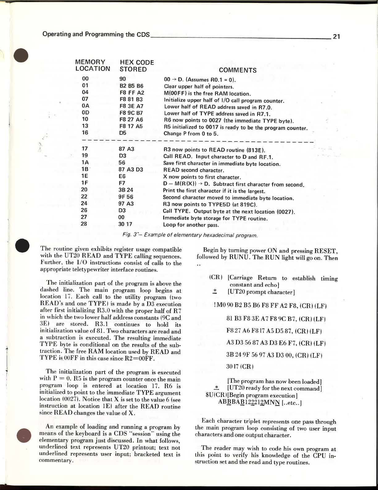
Operating and Programming the
CDS
_______________________
21
•
MEMORY
LOCATION
00
01
04
07
OA
OD
10
13
16
17
19
1A
18
1E E6
1F
20
22
24
26
27
28
HEX CODE
STORED
00
.....
D.
90
828586
F8
FF A2
F881
83
F8
3E A7
F8 9C
87
F8 27 A6 R6 now points
F8
17 A5
D5
87
A3
D3
56
87
A3 D3
F7
3824
9F
56
97 A3
D3
00
3017
Fig.
3--
Example
Clear upper half
M(OOFF)
Initialize upper half of I/O call program
Lower half
Lower half
R5
Change P
R3 now points
Call
Save first character
READ second character.
X now points
D - M(R(X))
Print
Second character moved
R3 now points
Call
Immediate
Loop for
(Assumes
is
the
of
of
initialized
from 0 to
READ.
the
first character
TYPE.
byte
another
of
elementary hexadecimal program .
COMMENTS
RO.1
= 0).
of
pointers.
free
RAM
location.
READ address saved
TYPE address saved in R7.1.
to
0027
(the immediate TYPE
to
0017
is
ready
5.
to
READ routine (813E).
Input
character
in
immediate
to
first character.
.....
D.
Subtract
if
it
to
immediate
to
TYPE5D (at
Output
byte
at
the
storage for TYPE routine.
pass.
in
to
be
the
to
D and RF.1.
byte
first character from second.
is
the
largest.
819C).
next
location (0027).
counter.
R7.0.
program
location.
byte
location.
byte).
counter.
•
•
The
routine given exhibits register usage compatible
with the
Further,
appropriate
dashed
location 17.
READ's
after first initializing
in which the two lower half address constants (9C
3E) are stored.
initialization value of 81.
a subtraction
TYPE
traction.
TYPE
with P =
program loop is entered
initialized to
location (0027). Notice
instruction
since
m a ns of th key boa
el "
und
underlined
commentary.
UT20
the 110 instructions consist of calls to
teletypewriter interface routines.
The
initialization
line.
The
Each
and
one
is
byte is conditional
The
free
is
OOFF
The
initialization
O.
R5
point
at
location
READ
An exampl of
mentary
erlined text
changes the value of X.
program just discussed.
represents
READ
in this case since
is
and
part
of
main
call to
TYPE)
R3.0
R3.1
Two
executed.
RAM
location used by
part
of
the
program
to
the
immediate
that X is
IE)
loading and
rd
i a
represents
user
TYPE
the
program
the
is
made
with
continues to hold its
The
on
the
at
after
CDS
UT20
input;
calling sequences.
program
utility program (two
the
characters
resulting immediate
the
R2=00FF.
program
counter
location 17.
set to the value 6 (see
the
running
"session"
is above
loop begins
by
a D3 execution
proper half of R 7
are
read
results of the sub-
READ
is executed
once
the
R6
TYPE
In
printout; text
bracketed
argument
READ
routine
a program by
using
what
follows,
text is
the
the
at
and
and
and
main
is
the
not
Begin by
followed by
(CR) [Carriage
$U(CR)[Begin
Each
the
main I rogram loop con isting
character
The
this point to verify his knowledge of the
struction set
turning
RUNU.
c
[UT20
*
!MO 90 B2
81
F8
A3
3B 24
3017 (CR)
[The
..!. [UT20
AB!!BA!!12~21!MN~
chara
and
reader may wish to code his own
and
power
ON
The.RUN
Return
onstant
B3
cter tripl et represe
and
echo)
prompt
B5
F8
27 A6 F817 A5
D3
5687
9F
program
ready
program
11
the
B6
3E
A7
A3
56 97
ntput
read
character)
F8
FF
F8
D3
A3
has
for
hara
and
the
execution)
type routines.
and
pressing
light will go on.
to
establish timing
A2
F8,
9C
B7,
D5
87,
(CR)(LF)
E6
F7,
D3
00, (CRI (LFI
now
been
next
command)
[ ..
etc
.. )
nts
one pass
of
cter.
(CR) (LF)
(CR) (LFI
(CR) (LF)
loaded)
two user
program
RESET,
Then
through
input
CPU
in-
at
Page 23
22
_________________
Operator Manual
for
the RCA CDS II CDP18S005
Programming Interface
to CSDP
Machine
program,
that
to
advam
available.
are
already
assembly
~re
"
available
system of
ief~rred
itself.
is
the
COSMAC
latter
non-trivial
reader
software
CSDP,
As
discussed in
RCA
202,
much
accomplished
Typically, a source file is
edited (if
reassembled,oo.,etc.
program,
isolated
reassembly of the source file.
code is ready for
hardware
further
concern here.
Already discussed
utility
keyboard
CSDP
compatible with
command)
to the
to write this file onto a
CDS
using this
the
automatic
compatible object file coming over
is
loaded into
There
paths.
already discussed. Second
Timesharing
which
simulation.
CDS
the
automatic,
language coding, even of a trivial
should convince
do
any serious
.age of
to as
The
Timesharing
set of
be
he
CDP1802
testing.
program
system is
CDS
First is
is
link (again via a
the
set
Veterans
aware
and
user
Microprocessor,
programs
programming,
familiar
support
should
of
the
during
and
(the
or
from
to
system. Clearly,
are
System link, via
implied in
And
in
of
simulation
either
RCA-developed
CSDP,
manual
with
systems.
skip
the
COSMAC
program
without
assembler
The
which
removed
loading
COSMAC
It
is this
to
load the
tape.
to
the
transmit
medium.
mechanism
the
CDS
three
the
the
third
direct-load
the
novice
programming,
of
software
the
programming
the
fundamental
facilities.
by
timesharing,
or
by
this
for
the
Manual
it
is
this
it is essential
the
facilities provided
If
the
this section.
Timesharing
Microprocessor,
developmenl
direct
constructed,
objects
simulator
time
by
and
Development
part
of
has
been the use of
One
ultimate
generate
required
this file over the telephone
it
tape
and
Of
concern
RAM
directly.
different
I/O
teletypewriter-CDS
is
the
an
use of
CSDP
is
the
modem)
process.
one
Support
programs
Development
former set of
for
MPM-202.
manual.
reader
Manual
CDS
to
the source code),
is used to
program
further
Eventually,
running
the
process
CDS
RAM
an object code file,
! M
format,
is
possible for
subsequently load
here, however, is
by
which the
the
data
I/O
appropriate
for assembly
Timesharing
which
programmer
should
support
necessity for
i.e.,
the
is
by
involvement.
editing
System) for
purpose of
telephone line
communication
teletypewriter-
is
take
aids
community
services
using a
hereafter
System
programs
CDP1802
For
the
To
do
any
that
the
by
these
not
using
for
the
MPM-
CSDP
assembled,
bugs
the
in
that
the
from
essential to
is
run
the
are
and
object
the
real
is of
'!
M'
the
the
and
(on
link
the
user
the
!M-
path,
modem,
and
System-
Some switching
Development
can
come either from
from
the
modem
A teletypewriter
external
set),
mechanize
modem-CDS
wired three-position switch.
position
CDS.
acts as
"TIMESHARING-LOAD"
established to allow
to
CSDP
previously assembled by
smission, the steps
load of the
object
necessary to properly initialize the utility program so
that
done
tivate
RESET,
keyboard
Initialization will be followed by a
prompt
will
$
is
be
RETURN,
mand
characters
UT20.
mand
TIMESHARING
initialization occurs, as discussed above.
terminal
LOAD
sequent
receives
object file transmission;
when it
DBG.
transmission,
commands
modem
and
the
the
In
the
normal
be
automatically loaded into
If
it
is
asslUned
control
CDS
Because
file on
it
is
ready
by temporarily switching
the
followed by
character
then
ignore all
detected.
done
at
to
CSDP,
in this
Thus,
to
is
and
characters are ignored
the
CSDP
1. $X
indicates
outputs
Assuming
will effect the transmission:
6.
End
name
mechanism
System serial
the
carrying
unit,
(e.g.,
an
an
added
various
paths.
terminal
"TTY-TIMESHARING"
program
CSDP
TTY
echo-timing control
It
is essential
a time
which
the
CSDP
switched
the
loading ! M
the
FiLe
RAM
of
TTY-CDS.
It
acts as
timesharing
data
that
required
RAM
follow.
will
command
for this
-CDS
indicating
subsequent
terminates
yet
command
final
is
mod
command
that
to the
terminal
that
the
following two alternative
Name
Location where
the
file
is implied by which
"Terminal"
keyboard/tape
data
generated
for instance, requires an
acoustic coupler
external "switchbox"
should
In
the
position, the link
from the
the
the
user
and
that
CSDP,
to effect
transmit
from
input.
path
RUNU,
that
inputs
that
this local initialization
before
the
after
the
string
"transmit
begun
e. At the
back
to
is
indicating
it is ready for a user
the
assembled
6.
Start
or
the
the
input
signal
reader
by
CSDP.
TTY-modem,
be
an appropriately
the
"TTY
I/O
device for the
position. it
terminal.
timesharing
CDS
memory.
has
been using the
an
object code file,
is
ready
an
automatic
an ! M-compatible
the
terminal, it is
This
initialization is
the
terminal to ac-
only,
completed. All sub-
and
followed by the
character
return
UT20
is
until a ! or
the
final carriage
"transmit" com-
occurrence of any
recognizable by
object file" com-
in
the
proper
point, UT20
Then,
TIMESHARING
by
UT20
the
beginning of
command
prompt
RAM
FiLe
device
file
is
Location
Name
which will
characters
or
or a'data
and
CDS"
In
the
system
for tran-
pressing
LF.
of the
ready.
'!
or
TTY-
the
until it
ready for
CSDP
6.
is the
to
is
It
Page 24

Operating
and
Programming the CDS
_______________________
23
•
•
fPceive
simulator
mally
just-completed
specified as
transmitted
tprminal.
will
continuation
loading
CDS
must
final
"relocatable"
$Y
RAM
apply to File
will
continuation
rpadable,
dress
for
memory
the
memory.
object-code
For
$X
TTY
result
the
RAM.
be
properly
CR.~
/':"
File
Name
Loc
$YTTY
result
in
since
value~.
"scatter
patches.
in
The
where
the
specified
generated
assembly.
TTY,
over
the
example,
#0
#lFF
the
transmission
form of
lowest
lRecall
initialized
!M
form
.
/':"
the
Name.
#20#150
transmission
form of
each
This
form
loading"
contents
These
the
object
telephone
(CRJ
the
part
that
Start
same
For
example,
(CR~
the
line
is
of
of
contents
as
the
result of a
If
File
code will
line to
of
the
! M object file,
(20016
is
subroutines
bytes~
the
utility
just
prior
more
compact
RAM
LOC
comments
of
the
-! M file
begins
with
particularly
semicolon-
CSDP's
are
nor-
Name
the
comma-
of
the
program
to
the
and
/':"
End
above
(more
an
ad-
useful
or
other
is
be
terminal.
;)
•.
The
code listed
program
the
listing,
earlier.
appropriate
automatic
The
generated
CSDP
CSDP
At
this point,
that
sequence
1.
Begin
typing
X
or
RETURN
2.
Switch
3.
Press
half
answer
4. Switch
the
position
5.
Press
minating
this
The
output
there
earlier ~ has
simulator's
again
returns
the
user
is,
input
of
UT20
load of
case, 3016
the
of steps
the
$ a
Y~,
the
RE
duplex~,
from
back
selector
the
transmit
TTY
but
without
yet.
terminal
SE
T, R UNU,
and
the
to
switch
at
this
final
the
is
point.
CSDP
bytes
received is
(the
same
now
memory.
follows
the
initialization,
object
as
#0 #30
receive
utility
TTY-MODEM
with
the
$X
or
file
follows:
command
(where"
typing
to
the
TTY
CR
program.
to
the
carriage
transmit
will
be
After
the
into
the * prompt
transmitted.
indicated
as
been loaded into
generating
DBG
instructions
$Y
command
to effect an
the
the
-CDS
or
LF
"CSDP
RETURN,
command.
that
prompt.
CDS
to
CSDP
a"
final
(for full
mode.
in Fig.
in
the
given
RAM.
is
either
carriage
mode.
as
Switch
LOAD"
hex
the
with
by
or
an
terFor
I
t
•
1£
the
CDS
has
been initialized properly,
befon'
loaded into
proeeed to
minal
faeilitips. i.e
S~
v('rsion of
SOl/ree
OO()
('omments in the listing
ddailed
CSDP
SAMPLE,
of this file with
the
transmission
RAM
run
in
TTY
program
the
the
program
tinwsharing
this
mand.
mpssage. By
or a RESET,
An
example
stem
session
the
program
program
I to
illustrate
rpader
hex code in Fig. 3.
is
entry
is
program.
it
prompts
TTY
automatically.
the
program
-CDS
..
$P
or
follows of a
using a Level-l
sample
is listed in
is
written
use
to
establish
entered
system,
made,
as
the
When
the
entering
(CR),
listing
begins,
mode,
$U
RUN P sequence.
program
to
of
should
from
a file
user
the
and
the
object
The
with
the
using
standard
by
means
CSDP-Development
assembly
given in Fig. 3.
Fig.
4.
For
begin
at
memory
the
ORG
statement.
be
sufficient
correspondence
Assume
the
named
calls for activation of
CSDP
terminal
the
CSDP
user calls for
diagnostics
that
keyboard
SAMPLE.
is
ready
with
file will
user
can
110
data
of
the
utility
language
this
example,
location
to
permit
with
this source
into
for a com-
the
command
an
assembly
printed
just
be
then
ter-
CDS
The
The
the
the
Once
the
DBG
$A
to
the
While
Development
terminal.
mand
$X
the
For
TTY
object
file is
System,
the
example
#0 #30 will
it
is also
being
given,
result
transmitted
printed
the
in
on
the
CSDP
!MOOOO
FFl)()B2B5B()FHFF A2FUSIB3FS3EA 7FS9CB7FU2SA6,
FH
WA5I?5H7 A3D356S7
FF301S
DBG
printed
On
command
• Refer to the Timesharing Manual for
COSMAC Microprocessor, MPM-202, for detailed CSDP
listing formaL Note
code
to
FFFFFFFFFFFF
on
the
terminal
the
other
hand,
$Y
TTY
user instructions and an explanation
displayed in the listing
the
contents
of
A3D3E6F73B2-~9F5697
during
for
the
#0 #30 will
that
for
forward
the simulated
does
the
same
example,
result
the
of
the
references, the
not
correspond
memory.
loading
in
RCA CDP1802
assembly
A3D3,
of
the
exactly
to
the
data
com-
RAM.
CSDP
Page 25
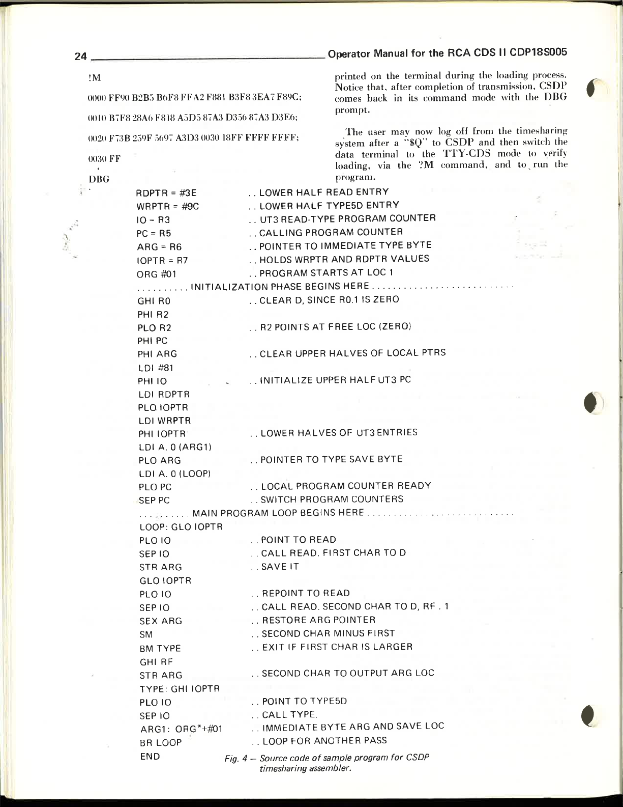
24
_________________
Operator Manual
for
the RCA CDS II CDP18S005
!M
printed
Notice
(JOOO
FF<)O
B2B:1
BM·'B
FF
A2
FBBl
B:WB
3EA7 FB9C;
oow
0020
00:30
B7FB2BM
F7:m
FF
2:19F
FBIB
:1697
A:105
A:m:3
B7A:3
0:3:16
0030 lBFF
B7A3
FFFF
03E();
FFFF;
DBG
RDPTR =
WRPTR = #9C
' .
.-
10
PC
ARG
10PTR
ORG
........
GHI
PHI R2
PLO
PHI
PHI
LDI
PHilO
LDI RDPTR
PLO 10PTR
LDI WRPTR
PHI 10PTR
LDI
PLO ARG
LDI
PLO
SEP
..........
LOOP:
PLO 10
SEPIO
STR
GLO
PLO 10
SEPIO
SEX
SM
BM
GHI
STR
TYPE: GHI 10PTR
PLO 10
SEPIO
ARG1 : ORG*+-#01
BR LOOP
END
#3E
= R3
= R5
= R6
=
R7
-#01
..
RO
R2
PC
ARG
#81
A. 0
(ARG1)
A. 0 (LOOP)
PC
PC
GLO
ARG
10PTR
ARG
TYPE
RF
ARG
INITIALIZATION
MAIN
10PTR
· . LOWER
· . LOWER
· .
UT3
· .
CALLING
POINTER
· .
· .
HOLDS
· _ PROGRAM
..
CLEAR
R2
· .
..
CLEAR
· .
INITIALIZE
· . LOWER
· .
POINTER
· .
LOCAL
..
SWITCH
PROGRAM LOOP BEGINS HERE
POINT
· .
· .
CALL
. .
SAVE
· .
REPOINT
..
CALL
· . RESTORE
· . SECOND
..
EXIT
· . SECOND
· . POINT
· .
CALL
IMMEDIATE
· .
· . LOOP FOR
Fig. 4 - Source code
timesharing assembler.
HALF
HALF
READ-TYPE
WRPTR
PHASE BEGINS HERE
0, SINCE
POINTS
UPPER
H.A.LVES
PROGRAM
PROGRAM
TO
READ
IT
READ.
CHAR
IF
FIRST
CHAR
TO
TYPE .
comes
prompt.
system
data
loading. via
program.
READ
TYPE5D
PROGRAM
PROGRAM
TO
IMMEDIATE
AND
STARTS
RO.1
AT
FREE LOC (ZERO)
HALVES
UPPER
OF
TO TYPE
READ
. FI RST
TO
READ
SECOND
ARG
POINTER
MINUS
CHAR
TO
TYPE5D
BYTE
ANOTHER
of
sample program
on
that.
back
The
user
after
terminal
ENTRY
ENTRY
COUNTER
TYPE
RDPTR
AT
LOC 1
...............
IS ZERO
OF
HALF
UT3
UT3
ENTRIES
SAVE
BYTE
COUNTER
COUNTERS
.......
CHAR
TO 0
CHAR
FIRST
IS
LARGER
OUTPUT
ARG
AND
PASS
the te
rminal
after
completion
in its
command
may
now log off from
a
"$Q"
to the
the
?M command.
COUNTER
BYTE
VALUES
LOCAL
ARG
for
PC
READY
...
TO
0,
LOC
SAVE
CSDP
PTRS
. . .
RF . 1
LOC
during
to
CSOP
TTY-CnS
. . . , .
......
the loading process.
of
transmi~si()n
mode
with
the
and
then
mode
and
.....
.
.......
.
CSOP
the
OBG
time~harin!-(
~witch
to vrrify
to .
run
- .
.
the
the
Page 26
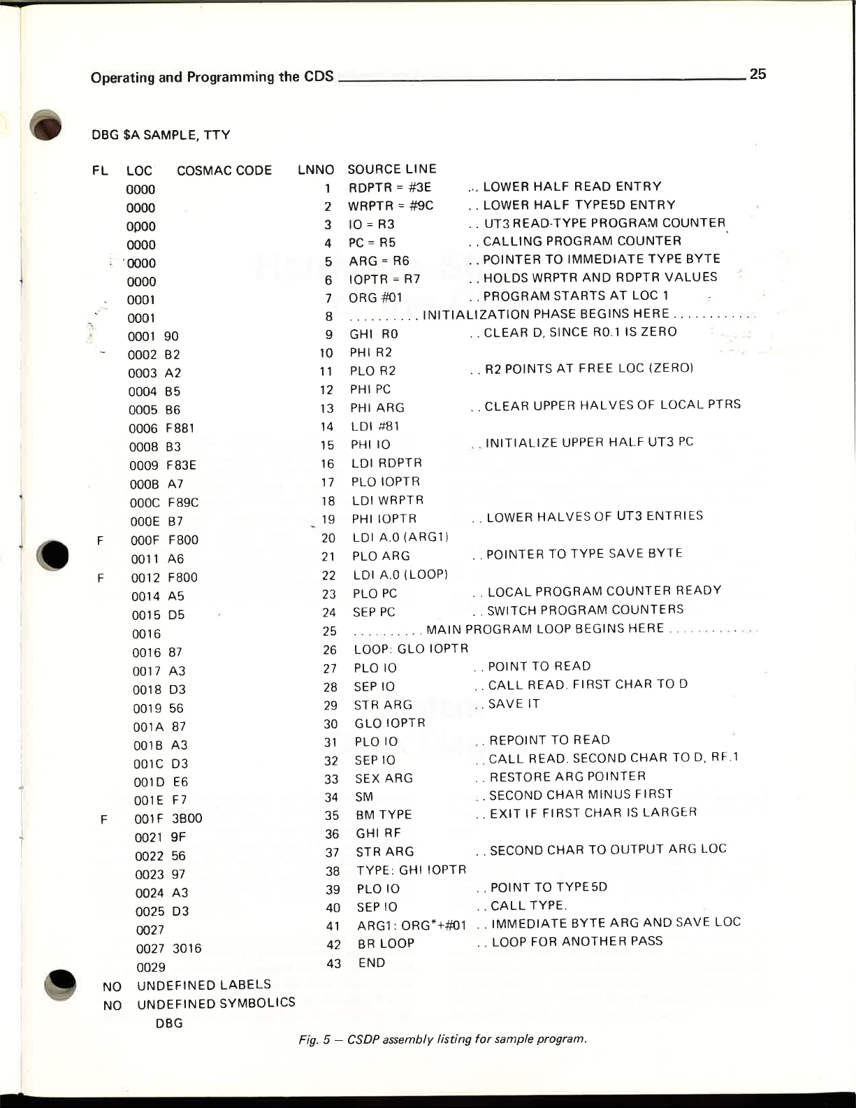
Operating and Programming the CDS
DBG
$A
SAMPLE,
TTY
25
I
..
I
I
I
1
FL
-.
F
F
F
NO
NO
LOC
0000
0000
OPOO
0000
'0000
0000
0001
0001
0001
0002 B2
0003
0004 B5
0005 B6
0006 F881
0008
0009 F83E
OOOB
OOOC
OOOE
OOOF
0011
0012 F800
0014
0015
0016
0016
0017
0018
0019 56
001A
001B
001C D3
001 D E6
001E
001F
0021 9F
0022 56
0023
0024
0025
0027
0027 3016
0029
UNDEFINED
UNDEFINED
COSMAC CODE
90
A2
B3
A7
F89C
B7
F800
A6
A5
05
87
A3
03
87
A3
F7
3BOO
97
A3
03
DBG
LABELS
SYMBOLICS
LNNO
Fig. 5 - CSDP assembly listing
SOURCE
RDPTR
WRPTR =
2
10
3
PC
4
ARG
5
10PTR
6
ORG #01
7
...
8
GHI
9
PHI
10
PLO R2
11
PHI
12
PHI ARG
13
LDI
14
PHilO
15
LDI
16
PLO 10PTR
17
LDI WRPTR
18
PHI 10PTR
19
LDI
20
PLO ARG
21
LDI
22
PLO
23
SEP
24
..........
25
LOOPGLOIOPTR
26
PLO
27
SEPIO
28
STR ARG
29
GLOIOPTR
30
PLO 10
31
SEPIO
32
SEX ARG
33
SM
34
8M
35
GHIRF
36
STR
37
TYPE: GHI 10PTR
38
PLOIO
39
SEPIO
40
ARG1:
41
BR
42
END
43
= R3
= R5
= R6
.....
RO
R2
PC
#Bl
RDPTR
A.O
A.O
PC
PC
10
TYPE
ARG
LOOP
LINE
= #3E
#9C
=
R7
..
INITIALIZATION
(ARG1)
(LOOP)
MAIN
ORG*+#Ol
HALF
READ
.'. LOWER
· . LOWER
· .
UT3
· .
CALLING
· . POINTER TO
· .
HOLDS
· . PROGRAM
· .
CLEAR
· . R2 POINTS
· .
CLEAR
· .
INITIALIZE
· . LOWER
· . POINTER TO TYPE
· .
LOCAL
· . SWITCH PROGRAM COUNTERS
PROGRAM LOOP BEGINS HERE
· . POINT TO
· .
CALL
.
SAVE
. REPOINT TO
· .
CALL
..
RESTORE ARG POINTER
· . SECOND
..
EXIT
· . SECOND CHAR TO
· . POINT TO
..
CALL
· .
IMMEDIATE
· . LOOP FOR
for
sample program.
HALF
READ·TYPE
PROGRAM COUNTER
IMMEDIATE
WRPTR
STARTS
PHASE BEGINS HERE
D.
SINCE RO.l IS ZERO
AT
UPPER
UPPER
HALVES
PROGRAM
READ
READ
IT
READ. SECOND
IF
TYPE.
FI
.
READ
CHAR
FIRST
TYPE5D
BYTE
ANOTHER
ENTRY
TYPE5D
AND
FREE LOC (ZERO)
HALVES
RST CHAR TO 0
MINUS
CHAR
ENTRY
PROGRAM
TYPE
RDPTR
AT
LOC 1
OF
HALF
UT3
OF
UT3
ENTRI
SAVE
BYTE
COUNTER
CHAR
FIRST
IS
LARGER
OUTPUT
ARG
AND
PASS
COUNTER
BYTE
VALUES
...
. .
.....
LOCAL
PTRS
PC
ES
READY
..
...
ARG LOC
... ... .
TO
D. RF.l
SAVE LOC
'
Page 27
26
___________
,
____
Operator Manual for the RCA CDS
II
CDP18S005
f
.....................................
....
I
i
I
.......
'
Page 28
•
_________________________________________________________________
27
•
Hardware
of
This
section of
"top
a
of
over-all system block
sufficient detail to explain
of the modules
and
order"
This
of each of
to provide sufficient detail (signal mnemonics, timing
down"
the
control
signals
overall
COSMAC
explanation
and
paths
are
diagram
the
modules.
the
manual
Development
to
indicate all of
in the system. -A few "second-
omitted
is followed by a block
is organized to a present
of the
hardware
System.
diagram
These
is given containing
the
basic functions of each
the
essential
at
this stage for simplicity.
diagrams
structure
First,
diagram
are
designed
the
an
data
Structure
CDS
information, etc.
individual module logic
D)
should be unnecessary.
nector pins to signals
detail
is
found in
AppendixA.
A
fundamental
structure
COSMAC
described in the
Pl802
of the
COSMAC
I so
that
the
prerequisite to
CDS
CPU
interface
User
Microprocessor,
diagrams
is
backplane
is a detailed familiarity with
Manual
further
The
omitted
and
user analysis of
(given in Appendix
assignment
at
this point.
wiring schedule
understanding
instruction set, as
for
the
RCA
MPM-201.
the
of con-
This
in
the
the
CD-
I
!
•
The
broad
System is indicated in Fig. 6.
terfaces with
and
with a memory system to its left.
and
indicators on
diagraml
CLOCK
eontains the system clock.
Most
of the signal
with signal mnemonics in parentheses.
I i:j I
is
used to denote a parallel
labeled with a
for example,
parallel signals A14, A13
organization of
an
I/O
system to its right in the
the
Control
communicate
and
CONTROL
paths
unique
A(l4:
121
the
The
Panel
with the system
Module,
in
the
diagram
set
index in
represents
and
the
A12.
range
the
CPU
(at the
of signals,
Note
System
Block
Development
module in-
diagram
The
switches
top
of
through
which also
are
labeled
The
notation
each
ito
j.
Thus,
bundle of
further
three
that
Diagram
where additional
from the letter
zero.
the
the
The
diagram
number
assigned.
Physically,
card
nest with 25 sockets for logic cards interconnected by
a power supply, a chassis which will
rack
or
mounted
emphasis
"0",
superscript after
denotes the plug-in connector position
in
the
CDS
the
Development
means
a cabinet,
control switches
and a hinged
is
a
"~"
each
next to
of a
printed
and
required
is
used
for the
module
which
System
circuit
mount
panel
indicators.
to distinguish it
name
the module is
consists of a
backplane,
on which
numeral
in
the
or
slot
via a
19"
are
Page 29
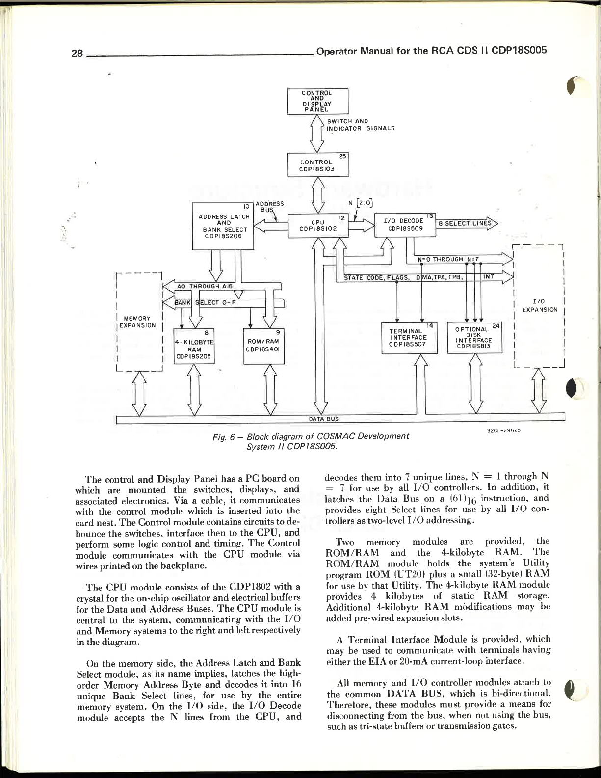
28
___________
•.
r ---- l
I
I
I MEMORY
I EXPANSION
I
I
I
L _
ADDRESS LATCH
AND
BANK
SELECT
CDPI8S206
~-:::-=
4-
KILOB'fT
RAM
CDPI8S205
~-;-;:-l
_ _ _
10
'---
ROMI
CDPI8S401
___
---,
RAM
Operator Manual
ST.l,TE C
ODE. FLA
TERM INAL
I
C DP
for
the
~
N~=~0
~~--
GS. D MA.TP
NTEP~ACE
185507
RCA
~T~H~R~0~U7
--
A.
TPB. IN
14
CDS
G~H
~N~=~7
----~1
~~~
OPTIONAL
DISK
INTERFACE
CDPI85813
II
CDP18S005
"'----1
-'r
l
EXPANSION I
24
IIO
__ J
I
I
I
1
I
I
I
I
I
I
The
control
which are
and
Display
mounted
Fig. 6 - Block diagram
Panel
System
has a PC
the switches, displays,
/I
board
CDP18S005.
on
and
associated electronics. Via a cable, it communicates
with
the
control
card
nest.
The
bounce
perfonn
the
some logic control
module communicates with the
wires
printed
The
CPU
crystal for the on-chip oscillator
for
the
Data
central to the system,
and
Memory
in the
diagram.
On
the
memory side,
Select module.
order
Memory
unique
Bank
memory system. On
module accepts
module
Control
which is inserted into
module contains circuits to de-
switches, interface
and
on the
backplane.
module consists
and
Address Buses.
communicating
systems to
as
Address
its
the
right
the
Address Latch
name
implies. latches the high-
Byte
Select lines, for use
the
110 side , the 110
the
N lines from the
then
of
and
to
the
CPU,
timing.
the
and
The
The
CPU
module via
CDP1802
electrical buffers
CPU
with the 110
and
left respectively
decodes
by
the entire
CPU,
the
and
Control
with a
module is
and
Bank
it
into 16
Decode
and
92CL
of
COSMAC Development
decodes them into 7
unique
= 7 for use by all 110 controllers.
latches th e
Data
Bus
on
lines. N = 1 through N
a (61116 instruction,
- 2
In
addition. it
provides eight Select lines for use hy all 1/0 controllers as two-level
Two
memory modules
ROM/RAM
ROM/RAM
program
for use by
ROM
that
provides 4 kilobytes of static
Additional 4-kilobyte
added
pre-wired expansion slots.
A
Terminal
may be used to
either the
All
EIA
memory
the common
Therefore, these modules
disconnecting from
such as tri-state buffers
110
addressing.
are
provided.
and
the
4-kilohyte
module holds
the
RAM.
system's Utility
(uT201 plus a small (32-bytel
Utility .
The
4-kilobyte
RAM
RAM
RAM
Interface
communicate
or
20-mA current-loop interface.
and
110 controller modules
DATA
BUS,
the
modifications may
Module
is provided, which
with
tenninals
which is hi-directional.
must
provide a means for
bus.
when
not
using the
or
transmission gates.
962
5
RAM
module
storage.
having
attach
and
the
The
be
to •
~
bus.
Page 30
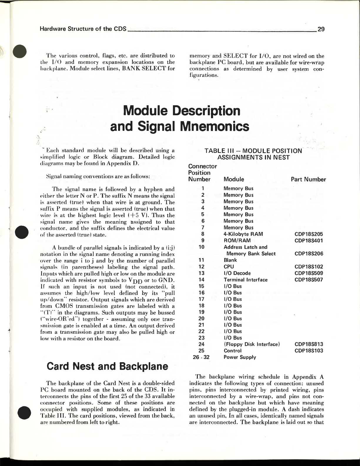
•
Hardware Structure
The
various
the
110
hackplane.
and
Module
control,
memory
of
the CDS
flags, etc.
expansion
select lines,
____________
are
distributed
locations
BANK
SELECT
on
to
the
for
_____
memory
backplane
connections as
figurations.
and
PC
SELECT
board,
but
determined
_ _
for
_______
110,
are
available
by
are
not
user
wired
on
for
wire-wrap
system con-
29
the
~
•.
and
-
Each
standard
~implified
diagrams
Signal
either
is
asserted (true I
suffix P
wire
signal
conductor,
of the asserted
notation in the signal
over
signals (in
Inputs
indicated with resistor symbols
If
such
assume!"!
upl
down"
from
"(1'1" in
("wire-OR
~mission
from a transmission
low with a resistor
logic
may
naming
The
signal
the letter N
means
is
at
the
name
A
btmdle
the
range
which
an
the
resistor.
CMOS
the
'ed "I
gate is
module
or
be
found
conventions
name
or
when
the
signal is
highest
gives
and
the
suffix defines the electrical
(truel
of
parallel
i to j
parentheses I labeling
are
pulled
input
is
highllow
Output
transmission
diagrams.
together -assuming
enabled
on
will
Block
P.
the
state.
diagram.
in
Appendix
are
is
followed
The
suffix N
that
asserted
logic level
meaning
signals
name
denoting a nmning
and
by
high
or
not
used
level defined by its
signals which
gates
Such
at a time.
gate
may
the
board.
Module
Signal
be
described
D.
as follows:
by a hyphen
means
wire
is
at
(true I when
(+5
assigned
is
indicated
the
number
the
Iowan
the
to
VDD
(not
are
labeled with a
outputs
also be pulled high
may
only one
An
output
using
Detailed logic
the signal
grOlmd.
VI.
Thus
to
by
of
parallel
signal
module
or
to
connectedl, it
are
derived
be
derived
Description
Mnemonics
a
and
The
that
the
that
value
a (i:jl
index
path.
are
GND.
"pull
bussed
tran-
or
TABLE
Connector
Position
Number
1
2
3
4
5
6
7
8
9
10
11
12
13
14
15
16
17
18
19
20
21
22
23
24
25
26 -
32
III -MODULE
POSITION
ASSIGNMENTS IN NEST
Module
Memory
Memory
Memory
Memory
Memory
Memory
Memory
4-Kilobyte
ROM/RAM
Address Latch
Memory Bank Select
Blank
CPU
I/O
Terminal Interface
I/O
I/O
I/O
I/O
I/O
I/O
I/O
I/O
I/O
(Floppy Disk Interface)
Control
Power Supply
Bus
Bus
Bus
Bus
Bus
Bus
Bus
RAM
and
Decode
Bus
Bus
Bus
Bus
Bus
Bus
Bus
Bus
Bus
Part Number
CDP18S205
CDP18S401
CDP18S206
CDP18S102
CDP18S509
CDP18S507
CDP18S813
CDP18S103
•
Card Nest and Backplane
The
backplane
PC
board
mounted
terconnects the pins of
connector
occupied with
Table
III.
The
are
numbered
of the
positions.
supplied
card
from
left
Card
Nest
is a double-sided
on
the
back
of the
CDS.
the
first 25 of
Some
of these positions
modules,
positions, viewed from
to
right.
the
33 available
as
indicated
the
It
in-
are
in
back,
The
backplane
indicates
pins, pins
interconnected
nected
defined by
an
are
the following
interconnected
on
the
the
lillused pin,
interconnected.
WIrIng schedule in Appendix A
types
of connection: lillused
by
by a wire-wrap,
backplane
plugged-in
In
all cases, identically
The
but
module. A dash
backplane
printed
which
and
is
have
laid
wiring, pins
pins
named
out
not
conmeaning
indicates
signals
so
that
Page 31

30
_________________
Operator Manual
for
the
RCA
CDS II CDP18S005
signal flow is
printed
connectors.
interconnections
backplane.
wiring for some
con,nections
One
•
d~cumentation
microprocessor
power supply voltage
high signal level.
CPU
plug-in
labeled
label
"VCC"
Another
a
higher
speed,
if
the power
(whose level
data
sheet labels
which
both
volts. the user
alternative
connecting logic
removed by
ground
Each
of Fig. 6
Block
show
pear
Diagram
the
when viewed
front. memory is
system
is
Some
and
inserting
horizontal,
wiring
connects
Note
If
the
and
wrap
notational
and
should
that
are
user
reason,
inconvenience between
i.e.,
identical pins on
almost
made
on
wishes
he can
his own.
the
data
be explained.
VDD
This
voltage is connected on
"V
board
CC"
is
on
not
to
the
the
CDP1802
used in
microprocessor pin (40)
power
supply
desired.
supply
may
positive
voltage level
In
the
CDS,
voltage labeled
be 5 volts
this
pin as
CPU
should
not
notations. A ground
ground
the
user
if
he
in his
system.
of
the
solid boxes in
corresponds
and
to
a supplied module.
the
backplane
modules generally left
from
the
on
the
right
on the left.
precaution
should
modules
(FROM
CONTROL
into
the
BOARD)
wherever possible
different
all of
the
printed
the
exposed side of
to
modify the
scratch
backplane
out
undesired
the
sheet for the
(+5
volts) is
microprocessor
CDS
may
to
this
pin
CDP1802
In
the
CDS,
the
standard
pin
data
sheet.
documentation.
be connected
achieve
is connected to
"CPUPWR"
or
higher).
"V
supply
be
to
has
the
The
0
0",
For a CDS
voltages are
confused
strap
chassis.
an
alternate
CDS
Block
CDP1802
by
is provided
It
may
Diagram
Both
wiring schedule
to
right
as
they
backplane
and
be
exercised in removing
CDS
side.
the
110 side of
nest.
From
The
the
signal
the
CDS
the
the
(16)
The
to
higher
for
at
these
be
safety
the
apthe
the
module
cards
are keyed so
improper
However, it
card
taken
card
contact
removal. A
or
A to
positions
is
removal. When removing a
to exert a lateral force.
lmnecessarily.
to be dislodged
short
B,
for example) can
develops after a
careful inspection of
visable before
el
ectronics.
Special care should
serted into
or
because the socket
and-down
motion
that
they
cannot
or
with
improper
possible for a key to
without
It
is
also possible for a connector
as a result
across
to
an
adjacent
then
card
removal
the
attributing
be
removed from
has
no key to limit
or
improper
and
connector
the
taken
the
card
be inserted in "
orientation.
be
pulled
card,
care should be
twisting
of
improper
contact
occur.
If
later reinsertion,
involved is ad-
problem
when
extender
to failed
cards
card
harmful
slot insertion.
out
by a
the
card
(1 to A
trouble
are in-
socket
up-
CPU Module CDP18S102
5
The
CPU
Development
IS
the
System.
memory, multiplexing
dress over a one-byte
manages
and
request,
flags.
encoded
instruction
a bidirectional one-byte
reacts to external signals -
DMA
It
transmits
CPU
state.
(I
= 6), it
output
two
When
timing
field of the instruction.
the
CDP1802
201, for details of
Fig. 7 shows
circuit module. All
backplane
2 MHz
COSMAC
the
the
connector
CPU
basic
named
for use by
heart
It
the
of the
controls
sixteen-bit memory
memory
address bus.
data
interrupt,
request,
and
pulses,
executing
transmits
Refer
to
the
the
User
Microprocessor,
operation.
logic contained on
signals
e
LK
the
OUT
are
system.
COSMAC
and
addresses
bus.
It
DMA
four
external.
or
syncs,
an
input/output
three-bit
Manual
brought
ad-
senses
input
and
"N"
for
MPM-
this
to
the
It
A
!
an
DB~:O]-P
Fig.
7 -
CPU
WAIT-
N
CLEAR-N
Q-P
L :
---
(2)
(8)
(~)
~
¢
.... -----
COP
~
o------o--PI-X
LK2
SC[I:O}P
N~:O]-P
CPUPWR
(PIN40)
tV
(PIN
16)
Module CDP18S102 block diagram.
1802
(~l
(2)
(8)
(4)
PI-Y.21
+v
IINT-N
MWR-N
lTPA-
TPB
- P
DMAIN-N
DMAOUT-N
P
EF [4:
0-N
92CM-
29611
Page 32

•
Hardware Structure of the CDS
The
internal
with a
internal
fered clock
developed
llser
clock
pr()p~iate
cit:cllits
lloilllected head-to-tail,
:When
·t'nabling
Because
transmit,
(disconnect) when
Lhe
operation
LIlt' inbound devices.
during
instruction
the
Lhe
2-MHz
may
oy
Thp
Data
MRD-N
opposite direction is
an 110
f)
Hel.Oster of
The
memory
backplane
oscillator on the
crystal.
clocks used
output
module
remove
driving pin 12 of this
clock signal.
as
the
outbound
is
the
Bus
is
shown.
is
inbound
they
in
progress,
operation
is
executed,
the
address
as A17:0)-P .
This
by
the
is provided for use
requiring
crystal,
buffered
The
true,
drivers require a low level to
are
MRD
The
CPU
by a set of tri-state
drivers on each line
and
controlled as to direction.
the
output
tri-state
in a high-impedance
is
true.
enabled
in
which case
reason for
is so
the
data
as
lines
oscillator provides
microprocessor. A buf-
a controlled clock.
then
well as in memory.
are
__________________________
CDP1802
provide
module
of gate B is
driver
When
the
that
byte
buffered
is utilized
the
by
any
user-
The
an
external
with
an
ap-
driver
are
high,
to
transmit.
state
MRD
is false,
unless
gate A turns
when
may be stored in
an
inbound
an
and
sent
110
on
path
input
to
Power
pin
l()
pin 40
are-connected
and
pin X respectively
link
LK2.
in
order
voltage on pin
for
maximum
It
is necessary
this reason, it is
LK2
resistor (approximately 1 kilohm) replace
additions will
from raising
The
resistor is to limit
drive into
Control Module CDP18S1 03
The
ween
See Fig. 8 . .
to
the
(V
CC)
powers
(VDD)
as
the
powers
to
To
operate
to gain speed,
voltage
shown in
prevent
+
VDD
Pin X lmder
Control
control/display
CDP1802
the
the
internal
backplane
and
with a
cut
X.
Consult
ratings.
that,
at
all times, V
recommended
Fig.
7,
and
possible
without
the
those circumstances.
Module
provides
panel
is
connected
chip
interface circuits
circuits.
connector
connected
higher
LK2
the
a voltage on
current
voltage on
and
provide
CDP1802
CC,;:;;;
that
that
a current-limiting
damage
that
the
and
the
31
to
two pins:
and
These
pins
pins Y
a diode replace
and
21
together
data
VDD'
LK1.
to
the
CPUPWR.
+ V
interface bet-
system logic.
Ii
DD
via
VDD
higher
sheet
For
These
device
may
•
The
incoming signals
N.INT-N,DMAIN-N,
nl'~ative
IlO
U
sl-'rs
transmission gates
more
manner.
signals,
eonnection
of these lines
than
one device
have
is
made,
JI
FROM
CONTROL
PANEL
SWITCHES
should
EFI-N,EF2-N,EF3-N,EF4-
and
DMAOUT-N,
pull-up resistors
the
inputs
provide tri-state drivers
to
pull
them
may
use
each
LOA~
SINGLE STEP
EXT WAIT-P
EXT
-~--'"
CLI!:.~-P
-t-~-t.
SCG-P
SCO-N
~_---<..r.1--=~::---1
so
are logically false.
to
ground
line in a wired-or
being
that
when
or
so
that
RNU-P
-r---,...J
The
control panel switch
the control
interfaced with
circuits
The W AIT-N
CDP
control modes:
OMAO-N
RUN-N
module
and
logic to control
1802 are controlled
DB
WAIT-
CLEAR-N
SCI-P
SCO-P
Q-P
92CM-29612
contacts
via
connector
appropriate
the
and
CLEAR-N
to
produce
RESET,
[7:0]-
A
&:O]-P-{>-
RUN,
P
-{>-
N
1-{>-
are
J1.
These
de-bounce
CPU
mode.
inputs to
one of
LOAD,
TO
DISPLAY
BOARD
JI
brought
or
or
PAUSE.
lines
pull-up
the
four
to
are
the
•
Fig. 8 - Control Module
COP
18S103
block
diagram.
Page 33

32
_________________
Operator Manual
for
the
RCA
CDS
II
CDP18S005
Depression of
W
AIT-N
and
LOAD mode, in which
memory using
Depression of
CLEAR-N
asserted
the·CPU into the
Depression of
.
WAIT-N
'\' lh
' R
-Addr ,
RUN
-p j . a s
and
mod.
Latch
memory address
Utility
of
one
program.
When
RUN
machine
the
U or
Successive depressions of a R
execution of
the
CLEAR-N
DMA-IN.
the
RESET
RUN P or
CLEAR-
In
rt
a,
and
8XXX
SINGLE
RUN
cycle,
stopping
the
program,
LOAD
to
be
data
RESET
and W AIT-N
mode.
RUN
fa
lse,
the a of
and
go via lh
Bank
el t Modul where
is forced
STEP
switch is set, depression
P results in
between
UN
one
switch causes
asserted, defining
may
be loaded into
switch results in ·
false which
U results in
putt
ing the
RUN
ba
kplanetothe
and
the
RUN
TPA
switch will cause
machine
time.
Inputs
modes are provided.
CLEAR-P
Each
through
CLEAR,
on
WAIT-N.
An
determine when 3
When
extinguishing
operator
RUNP.
made,
for external
are
available
manipulation
EXT
on
WAIT-P
the
backplane
of the control
is provided with a pull-down resistor
one
OR
gate
directly controls
e.g.,
a high
on
EXT
Idle
detector
Idle
is
detected,
can
terminate
Then
and
following the
circuit counts
or
more
the R UN
a single
WAIT-P
sequential
the
RUN-N
light on the panel.
the Idle
state
DMAOUT
S2
state, processing will re-
causes a low
SI
SI
states occur.
line will go
by depressing
request will
Sllme with the instruction following the Idle.
RUN
light will be
running
N.
again.
The
Data
CLEAR-N,
the display panel via
Bus
turned
and
SCO-N,
on when
Address Bus as well as
SCI-N
Jl.
Each
the
program
and
Q-P
of these lines
fered.
An interface
tachment
switches from the
connector
of the optional Microterminal. Control
Microterminal
paralleled with those from
J2
is provided for at-
are
the
Control
Panel.
electronically
both
puts
both
CPU
into
,l
he signal
starts
mode for
and
TPB.
cycle
at
and
EXT
connector.
and
WAIT
and
states to
high
The
The
starts
WAIT-
are
sent to
is
buf-
the
the
be
Address Latch and
Bank Select Module
CDP18S206
The
Address
and
decodes the high-order
address
for use by all memory modules. Fig. 9 is a
block diagram of this module. A(7:01 from the
module is latched into
The
outputs
the backphllle connector
The
decoder
BSfF:OI. which go to the
a
MBDS-N
Fig. 9 - Address Latch
These
field into sixteen blocks of 4-kilobytes each.
supplied 4-kilobyte
lowest-order bank-select signal. BSO-P,
located starting
module is wired to BS7-P locating its starting address
at
~WOO.
control panel switch, causes the decoder to see A15 as
true.
Thus.
will cause the
location of Utility software.
Memory
provided
inhibited. A pull-up resistor
conneetion
the
Bank
input
may be used to logically disconnect the memory
system when
Latch
and
Bank
Select
Module
byte
of the memory
an
eight-bit register by
of this register. AIl5:81, are provided on
and
to a one-of-lo decoder.
outputs
RNU - P -
-
----<_~
CDP18S206
signals
at
RNU,
a signal derived from
after a
starting
Bank
so
that
is
made
Select decoder
another
are
backplane
TPA
---,
block
break
up
RAM
address
RESET.
address to
De-Select
all
to this pin.
is
to
16
Bank
Select lines,
connector.
A[7
:0 J-P
92CS-29613
and
Bank Select Module
diagram.
the 65-kilobyte memory
module is wired to the
so
that
O()OO.
The
ROM/RAM
the
depression
fMBDS-NI
Bank
is
provided so
operates
be
substituted.
be
Select lines can
the
of
8000, which
is an
that
line is false.
normally.
RUN
RUN
stores
CPU
TPA
The
it
U
is
the
input
be
if
no
and
This
.
is
U
Page 34

•
Hardware Structure
Memory
backplane
Latch
locations. A(l2:81
backplane,
module
availanle
wire~
BS(F:Ol,
and
must
suit
the
:'Memory
? formation on
address lines A(7:01-P
from
the
and
Bank
Select
from
the
to
all
memory
at
the
backplane
by
the
user
are
available
be wired
user's system
Addressing
adding
of
the CDS
CPU
module
address
Address
if needed.
on
to
appropriate
organization.
and
additional
_____________
are
printed
module
lines
Latch
locations. A(l5:131
connector
The
the
to
and
to all
are
printed
and
Bank
backplane
memory
Refer
Expansion"
memory
on
the
Address
memory
on
Bank
and
may
Select lines,
connector
modules
to
Section
for in-
to
the
CDS.
the
the
Select
are
be
to
_____________
The
select lines
group
of devices I is assigned a
When
the
device sees its code on
responds to
select lines allows a device (or
and
six
output
excluded because
select function.
In
most
systems,
select code, by software
eight code.
the
select lines.
output
and
48
are
I/O
instructions.
instructions.
Then,
each
This
unique
used as follows.
The
they
are
dedicated
it
will be sufficient
convention,
device
technique
input
instructions.
Each
unique
Thus,
group I to
need
eight-bit code.
the
each code in
61
and
to
look
allows for 48
33
device (or
select lines, it
the
use six
to
to
a one-out-of-
at
input
69 codes
the
'group-
restrict
only one of
unique
are
the
•
--+
1/0 Decode Module
CDP18S509
The
purpose of
provide
and
Fig. 10 shows
module.
= 1
I/O
when
bits are provided
lines SELO-P
output
through
decoded
to
provide a two-level
The
three
through
operation,
An
output
instruction
N = 7. Because N = 0 is
the
port
through
port
may
the
input
the
110
N-bit
addresses for all
the
functional
N lines
zero
decode is
latches a byte
61
is executed.
to
the
backplane
SEL7-P.
be
read,
port.
Decode
I/O
addressing
block
are
decoded
using
DB
Module
I/O
diagram
into 7 lines, N
not
used.
from
the
The
eight
connector
The
contents of
input
instruction 69,
~:~-P
RESET
is
to
devices
capability.
of
this
not
a valid
Data
Bus
latched
as
select
the
Automatic
disabling
set, enables the
flip-flop is set
reset
by
software control (by
RNU
(ENABLE)
button
pin
level
start
backplane.
141
to
further
I/O"
Section.
will also
The
control flip-flop
9 of slot 13
1/0
a two-level 110
The
select lines SEL(7:01-P
and
additional
discussion of
under
o
m,......N
Il:
a...nal
::!:
......
ZO
means
two-level
chip
by
depressing
clear
to
is always
SELO-P is
disk
(slot
user
Input/Output
RESET
(DISABLE)
are
provided
I/O.
The
select
input
depressing
the
UT20).
the
ground.
enabled
program
241
interfaces.
I/O
this
the
RESET
Selection Register.
can
be
With
and
correctly.
prewired
controllers
subject, refer
Interfacing
for
enabling
control
Note
flip-flop,
of
the
I/O
RUNU
button,
that
locked
out
pin 9 grounded
reset.
RUN
are
available on
to
the
terminal
Others
as
desired.
to
can
and
when
ports.
The
button
the
"Two-Level
in
or
under
RESET
by
wiring
P will
be
wired
For
the
and
two-
the
(slot
next
a
i
I
~
MRD-N
TPB-
MRD-
TWO-
s~
P
8
N
Fig.
-----,
10 -I/O
diagram.
Decode Module CDP18S509 block
LEVEL
CONTROL
(PI-
TLIO-N
9)
ONE
OF
8
DECODE
7
N=
[7:~-P
92CM-29614
Page 35

34
_________________
Operator Manual
for
the
RCA
CDS II CDP18S005
ROM/RAM
Module
CDP18S401
The
primary
is
to
hold the system utility software. See Fig. 11.
this purpose,
provided.
byte
or
1024-byte
packages
programmed
Each
may
CDP1832
function of
two
socketted 24-pin positions
of
these
ROM
be
light-erasable
BSB-P
MRD-N
the
ROM/RAM
locations accepts either 512packages. Also, these
EPROM's
or
CDP1834
MEMORY ADDRESS
A
[9:q]
ROM's.
______
BI-
THREE-STATE
Module
ROM
or
mask-
~
--------
ROM
CHIP I
DIRECTIONAL
BU
FFER
For
are
MICROTERMI
ROM
4-Kilobyte RAM Module
CDP18S205
The
4-Kilobyte
12, provides the basic static
CDS.
One module
memory
memory
identical,
dresses
added
NMOS
~~--------
BSB-P
MRD-N
may
expansion
but
by a Bank
module/:s-l. TIre basic
chips.
NA
ROM
RAM
Module,
is
supplied
be
expanded
area
by
provided.
are assigned to
Select line
RAM
~--------__,
CHIP2.
U9
92CS-
29615
32.-
BYTE
diagrammed
RAM
with
adding
These
the
wired
RAM
storage in
the system,
modules in
modules
appropriate
to pin X of
devices
are
in Fig.
the
and
the
are
ad-
the
256 x 4
l'
Fig.
Pin
X of this
BS8-P from the Address
the utility
program
module
starts
location is wired
Latch
or
Bank
at
memory address 8000.
Also on this module is a 32-byte static
(CDPI824)
utility software.
When
ROM
selects either
minal
position,
Various
specific link configurations.
circuit
required
The
select 1024-byte
(standard
Microterminal
a 2708,
to provide a small
It
starts
the
Microterminal
is inserted
utility
the
into
the
standard
ROM.
Microterminal
combinations
and
the
tables of Appendix D to define
at
memory address
location U8. A toggle switch
When
of
work
option is installed, its
utility
the switch is
ROM
is enabled.
ROM
Refer
to
link configuration for a given combination.
PC
board
is provided with pre-printed links
ROM
utility)
ROM
CDP1832,
packages in U7
and
either
(U8); the
or
CDP1834
512
package
with
links.
11
-
ROM/RAM
diagram.
to
Select so
RAM
area
8COO.
or
the Microter-
in
packages
the
detailed logic
or
1024 in
types
the
pre-printed
signal
that
chip
for
the
require
and
may
the
up
the
to
U9
the
be
Module
COP
BANK
SEL-P
MWR-N
A~I:~-P
A
[7:0J-P
MRD-N
The
each of
bits
RAM
18S401
Fig.
block
12 - 4-Kilobyte
block diagram.
address
the
32
are decoded
chip-enabled
bus
RAM
and
32.-
PACKAGE
RAM MATRIX
DATA
BUS
[7:0J
92CS-
29616
RAM
Module COP18S205
An:O)-p
is buffered
and
wired
packages. High-order address
sent
to
the
appropriate
groups
inputs.
-P
to
of
Page 36

•
I
i
Hardware Structure
The
data-in
packages
DB(7:0),
are
buffered onto
through
direction is controlled
MRD-N,
Select is true.
and
Thus,
it presents a
min~mizing
loading effects.
of
and
data-out
tri-state
by
all buffers
when
high
impedance
the CDS
lines from the
the
gated
the
Memory
are
enabled
the
module
________________________
system
Data
buffers.
Read
signal,
when
is
not
selected,
to the
Data
Terminal Interface Module
CDP18S507
The
Terminal. Interface
~
ith
serial/parallel
Program,
terminal.
provide
The
conversion routines in the Utility
an
module,
two interfaces, logically identical
different, for two types
conventions.
current
for a Teletype
provides
others designed to
Two
cables supplied
The
n connector provides a 20-mA
loop interface
or
similar
an
EIA
interface for
the
mechanical-Compatibility
interface .
Module,
ASCII
interface to a bit-serial
diagrammed
in conjunction
in Fig. 13,
but
of
serial interface electrical
and a paper-tape
terminal.
reader
The
the n terminal,
EIA
RS232C specifications.
with
the systems provide
to
either a
TTY
electrically
control
J2
connector
or
an
RAM
Bus,
The
Bank
Bus,
has
or
EIA
The
serial
ASCII
are
formed by strobing
flip-flop
67
Bit
reader
under
output
instruction is used to generate
7 of
the
Data
control flip-flop
characters
control of
Bus
Data
the
is used to set
and
same strobe.
Data
program
EF4-N
This
signal
select
makes
outputs,
the
Pressing
flip-flop
The
output
EIA
PT
Contact
from the
via
are conditioned by a select signal,
and
- voltage low (approximately -5V)
RDR
terminal
External
may
select
RESET
resets
be wired to
or,
true
if
all
on
the
Flag
left
the
the
paper
quiescent levels
- voltage low (approximately
closure
on
the 20-mA loop incoming
line produces a low (true)
EIA
incoming
data
line produces a low -'true)
N.
output
Bus
UT20
bit
6 to reset
is
transmitted
4.
Both
the
I/O
open,
time.
control
tape
are
then
on
EF4-N.
.1-1 35
to
the
terminal
bit
0 into
aD-type
TYPE
routines. A
the
strobe.
the
paper-tape
it
via
to
the
Utility
the strobe
the
and
SEL-P.
Decode module-
a pull-up resistor
panel
sets the
data
control flip-flop.
as follows:
OV)
data
A low on
on
the
EF4-
•
DB
[7:
sJ-
P -
RESET-P
----
DBO-P-~
T P B - P
------
N =7 - P
---------i
MRD - P
--
SEL-P--+---~
EF4
- N -
----;
------
----
---l
--,------1
-------.
-------i
2
f--
--.j
----
----~D
TRANSMISSION
GATE
Fig_
O
f---
--1
0
R CLOCK
~
R
O
r---1-
CLOCK
C
13 - Terminal Interface Module CDP18S507
block
----
diagram.
--
>-----
VOLTAGE
CURRENT
-.
CONVERSION
LOGIC
CONVERSION
CURRENT
VOLTAGE
CONVERSION
ErA
LOGIC
CONVERSION
TO
TO
LEVEL
ErA
TO
TO
LEVEL
-.
PAPER-TAPE
PT
RDR-N
{
r
r
92
CM-
296
READER CONTROL
2G-mA
CURRENT
OUT
EIA
20-mA
CURRENT LOOP
IN
{
17
ErA
LOOP
OUT
IN
Page 37

36
_________________
Display Board
The
display
panel assembly.
display units, six single
switches whose
method
Communication
of connector
..
signals required.
\ this
board
. provided.
fest of
the
Fig. 14 depicts
digit
is
driven by a
take
4 bits from
if
required,
for the display.
presents the
The
memory address
address
address byte.
board
It
threaded
for
mounting
with
n
and
Power
by
wires soldered into plated holes
This
power is always
system is supplied from
the
LATCH-DECODER
the
address,
and
re-encodes
The
front
characters 0 through
leftmost two digits
at
TP
bus
continuously to
mounts
contains
the
on
the
hinged control-
six hexadecimal digit
LED
displays,
bushings provide
board
to
the
panel.
the
Control
Module,
and
by
six
the
way
a flat cable, provides all logic
and
logic on
ground
the
are
+5
volts even
another
board.
supplied to
if
voltage.
Each
display
the
chip which
or
data
bus,
them
into seven segments
panel
hexadecimal display
latches
them
F.
latch
the high-order
A.
The
next
two
present
prov~de
the low-order
the
Operator Manual
It
must
displayed whether
In
the
SO
being fetched.
mayor
may
for
be
remembered
state,
the
In
the
not
the RCA CDS
that
or
not
memory
address
is
S1 state,
be
significant,
II
CDP18S005
the
address is always
is being accessed.
the
location of
the
memory
depending
addres
on
instruction being executed.
The
rightmost two display digits show the
Data
Bus contents continuously when the control switch is
in
the
BUS
position. When
110
position, the control module is conditioned to
provide a latch pulse
The
and
and
and
six single
CLEAR
SCI
from
the
system
LED's
lines to the
the
CPU,
RUN
lighted when the specified condition is logically
Momentary
U,
RUN
select
SINGLE
LAST
110
switches
action switches provide
P,
and
LOAD
STEP
or
BUS
display.
are
sent directly to
the
switch is in the
at
TPB
of
any
110
operation.
display
state.
CPU,
the Q
the
the
output
These
state
of the
state codes
from the
six displays
RESET,
functions. Toggle switches
or
CONTINUOUS
The
contacts
the
Control
Module.
LAST
WAIT
CPU,
true.
RUN
mode
of these six
data
the
SCO
are
and
(
s
,
;
I
1
BLi
S LATCH
ENABLE-N
DATA
BUS
MEMORYADDRESS
u:oJ
CONTROL BOARD
TPA
-
---I
~;~
--------------~~------
------
FROM
---.--
--~
W A
CLE
~--~
IT
- N
---------------1~---,
AR
- N
---------------1~--
SCO-N
-
----I
SCI-N
-
Q-N
RUN-N
- - -
------------------------_t----t_----t_
----------~--------_,
ADDRESS
LEO'S
.....
+5V
4
BUS/LAST
,----<:r
...-----<Y
t---~y
92CL-29618
--I
I/O
0----
0---
0---
0---
0--
o--SS-NO
LAST
LO-NO
RES -NO
RNP-
RNP-NO
RNU-NC
RNU-NO
I/O
NC
SW- N
Fig. 14 - Display board
block
diagram.
Page 38

Hardware Structure
of
the
CDS
__________________________
37
•
•
Disk
Module
Slot 24 of the
Interface
the disk drive
buffers,
di~gram
~
,
-
The
drive unit,
with
bils are
emitter
significant
generated by
strobe.
Data
output
eight bits are
op
en-collector
Data
recei ved by
instruction.
Module.
and a 50-conductor
is given in
first
output
is
the
1/0
select register set to 01. Seven
sent
open-collector
bit
is
sent
port
loaded
or
status
an
Interface
Option
CDP18S813
CDS
is reserved for
This
module
unit
through
Fig.
port,
written
to
is
the
transmitted
transistors
to
the
drive
gated
output
to
the
by
information
in
put
port,
drive
three
flat
IS.
used for
by a 65
unit
through a grounded-
transistor
by
the
port
unit
a 64
output
through
.
from the drive
which is
service
the
optional
communicates
byte
cable.
commands
output
driver.
request
to provide a clock
through
instruction. All
~ounded-emitter,
read
Disk
with
110
ports,
Its
block
to
the
instruction
command
The
least
(SR)
a second
unit
by a 6E
is
Microterminal Option
CDP18S021
Provision has
Microterminal
Microterminal
display
ROM
photograph
unit,
contammg
To
install
1.
Turn
Extract
2.
3.
Install
US. (The
4. Re-insert the
Insert
5.
J2,
the
Control
polarity
connectors.
6. Set
its
up
position.
been
and
consists of a
its cable
is
given in
the
Microterminal:
power off.
the
the
center
the
Microterminal
20-pin
connector
module
by
matching
the
switch on
made
to
allow installation of
its
ROM
hand-held
and
mating
a utility
Fig.
16.
ROM/RAM
ROM
of three 24-pin sockets).
ROM/RAM
in slot 25. Carefully observe
module
in the
on
the
the index arrows on
the
ROM/RAM
into
the
connector,
program
empty
module
cable
outboard
the
CDS.
keyboard
from slot 9.
24-pin socket
into slot 9.
connector
The
and
UTS.
into
side of
proper
module
and
the
the
a
A
to
•
OUTPUT'65'
'64'
OUPUT
DATA
BUS
[7;~
INPUT
'6E'
SELO
-P
-P
CPUO
Dr [7:
296
19
STROBE
DATAl
0J
i~g~us
CONTROLLER
TO
DISK
DRIVE
CONTROLLER
OUTPUT
COMMANDS
OUT
-I
1----
+-toI
Fig. 15 - Disk Interface Module CDP18S813
PORT
PUT
PORT
DATA
INPUT
PORT
f-S'--R
DAT
block
____
A 7:1
DATA
[7:0]
diagram.
--1
1--
tV
......
---
92CM-
Page 39

38
________________
Operator Manual
To
return
switch on the
position. This switching may be done while power is
on.
but
if the
power should be
for
the RCA CDS
to
standard
ROM/RAM
Microterminal
turned
off first.
II
CDP18S005
utility operation, set the
module
is
to
be
to its down-
disconnected,
i
.
Fig. 16 - Photograph
I.
S.
Microterminal
At this point, the display
Microterminal will
refer to the
Microterminal,
Although
Microterminal with
operation considerations apply to
CDP18S021.
Turn
power
Press
Instruction
that
RESET,
of
RCA COSMAC Micro terminal
on.
then
or
the
CDS
be
operative.
Manual
MPM-212,
manual
the
refers to the use of the
Evaluation
RUN
U on either
front panel.
and
The
for
RCA
for
operational
Kit,
the
CDS.
keys on
user should
COSMAC
details.
the
same
the
the
Power Supply Module
The
Power
former, rectifers, voltage regulators, pass stages,
heat
sinks.
on a
printed
transformer
CDS
chassis in the space beside the plug-in logic
modules. occupying slot locations 26
Appendix
AC
input
100.
115.220,
input
is fused
or
115 ·volts.
changed
220.230,
are: +
memory
requirements
Total System with
4-kilobyte
and 3-kilobyte
+12 V
+5
-5
The
V
V
12 V at
major
Supply
The
circuitry
circuit
bracket.
D,
Fig. D
taps
230,
at
It
to 0.75 amperes when the
or 240 volts.
0.5 A,
current
boards.
are given below.
NMOS
PROM:
mA
100
1.5
60
typical
mA typical
mA
typical
Module
and
heat
board,
19
are
provided for nominal voltages of
and
1.25
is
recommended
The
RAM
which is
This
module
for its
circuit
240 volts
amperes
Three
output
+5 V at 6 A,
drain
in the
memory
+l2V
+5
-5
consists of a trans-
sinks
are
mounted
mounted
is
installed
through
diagram.
rms,
50/60
when
operated
that
CDS
voltages provided
and
CDS
board
Total System with
4-kilobyte
and 3-kiIobyte
100
V
800 mA typical
V
60
on the
in
32. See
Hz.
at
the fuse
is operated
-5 V at
is
due
current
SOS
RAM
PROM
rnA
typical
mA
typical
and
the
The
100
be
at
0.5 A.
to
:
f
I
1
A helpful note
register
instructions,
register are displayed on
the Bus displays provide
location as
M(R(N))
front panel switch
readout.
may
but
observe
addressed
is
displayed.
be
Follow the
by
For
RUN
Development
Table
IV
summarizes
each signal, the source
added
to
the
use of
Microterminal
that
when the contents of a
the
CDS
address displays,
the
contents
the
register.
register read-out, use
U for single stepping.
all of
the
and
destination modules
of the memory
In
other words,
CDS
signals.
the
CPU
Manual
the
For
are
The
remaining system
and
take
less
Note
that,
kilobytes of
may
have to he powered from
System
listed.
signal
devices.
The
that
may he derived from
components
than
50 rnA from
typically, the
NMOS
CDS
RAM.
Signals
term
'USER'
in a
are all
the
+ 5 V supply.
can
support
Any additional memory
an
external
column
or
sent to user-added
CMOS
up to
12
supply.
designates a
Page 40

Hardware
Structure
of
the
CDS
39
•
•
1
•
TABLE
Signal Name
A[7:0)-P
A[15:8)
ANY
BS[F:O)
CDO[7:0)
CLEAR-N
"
CLEAR
CPU[7:0)-N
CPU
DB[7:0)-P
DI[7:0)
DMAI-N
DMAO-N
EF[4:1)
EX
EX
INT-N
LOAD
MBDS-N
MRD-N
MWR-N
N[2:0)
N=[7:1)
Q-P
RESET-OP
RESET
RNU-P
RUN-N
RUN P
RUN U
SCO[1:0)-P
SEL[7:0)
SINGLE-STEP
SW
TPA-P
TPB-P
UA15-N
WAIT-N
-P
I/O-P
-P
-N
SW
PWR
-N
-N
CLK External clock
WAIT
SW
-P
-P
SW
SW
SW
-P
Description
Low-order
bits
High-order memory address
bits
OR'ed
Memory
Data bits
interface module
CPU
From Microterminal
Command
interface module
+V
DD
Bidirectional
Data bits
to
DMA
DMA
Flag
External wait
Interrupt
From
Memory bank deselect User Address Latch
Memory read signal
Memory write signal CPU
N-lines
Decoded N-lines I/O Decode
Single
Reset signal
From panel switch Panel Control
Signal
program
Signal indicating con-
tinuous
From panel
terminal terminal
From panel switch Panel
State
Two-level enabling signals I/O Decode
Single-step
Early pulse in CPU cycle CPU
Late pulse
OR'ed
and RNU
CPU
memory
output
bank
from
clear signal
bits
supply
from
disk interface module
IN
request User
OUT
request User, Control
inputs
request
panel switch Panel Control
from
bit
output
to
run utility
SO,S1
code
lines CPU
control
in
output
wait
signal
IV
- CDS SYSTEM SIGNALS
Source
address
from
N-lines
select
disk
from
disk
to
CPU Power
data
bus
disk drive Disk Drive
to
CPU
input
to
CPU CPU User
CPU CPU I/O Decode, Control
from CPU CPU Terminal, I/O
from
control
cycles
or
Micro- Panel/Micro-
input
CPU
cycle CPU
of
A15 Address Latch
CPU
Address Latch
CPU Control
Address Latch Memory
Disk interface Disk Drive
module
Control
Microterminal Control
Disk interface
module
Supply/
User
CPU Memory, I/O, Control,
I/O, Terminal,
Control
User
User
CPU
Control Memory, I/O
Control Address Latch, I/O Decode
Control
Panel
Control
Destination
Memory, Address Latch
Control
Memory
CPU, Disk
Disk Drive
CPU
Terminal
Disk interface module
CPU
CPU
CPU
CPU
CPU
Memory, I/O,
I/O Decode, Terminal
Memory
I/O, Terminal, Disk,
Control
Display
Control
Control
I/O, Terminal, Control
I/O, Terminal, Disk
Control
Memory, Address Latch,
I/O Decode, I/O,
Terminal
Memory, I/O Decode, I/O
Control,
User
CPU
Control,
Terminal, Disk
Control
Page 41

40
_________________
Operator Manual
for
the RCA CDS
II
CDP18S005
(
Memory
and
To
aid the
Development System to
Memory Organization
"
)
The
total directly addressable memory space (65,
536_bytesl may
hanks
dress, A(l5:01, can
A(l5:121 being a
the byte within a
further subdivided into four
each (in which case
a
selected blockl
(A(l1:91 defining the block
identifying the byte within the selected block).
a block of memory.
given plug-in slot, external wiring of
on the connector in
block
respondsl.
ranges for the
of 4096
bank
and
~~
BANK BLOCK
NUMBER NUMBER
A [ 15:
Fig. 17 -
Each
memory plug-in module comprises a
numbers
user
be
bytes
bank
bank,
A(9:01 is the
or
MEMORY ADDRESS BITS
12)
A [ II: 10]
'-----y--'
NUMBER
A
Memory
(the
Thus,
memory
in interfacing the
added
memory
COSMAC
hardware,
considered as being divided into
each.
The
16-bit memory ad-
be
divided into two
number
(see
A(ll:lOl
Fig.
blocks
is a block
address
and
A(ll:OI
1 n A
bank
of 1024 bytes
number
of a byte within the
into eight blocks of 512 bytes each
,9
8 7 6 5 4 3 2 I
4
HALF-
BLOCK
[11:9J
~------~
2
address
When a module
number
PAGES
A [9,
~-----'vr--
256
PAGES
9
bit
and
v
WITHIN
BLOCK
0]
BYTES = I
A
[7:0)
vr------~
WITHIN I
HALF-BLOCK
A [8:
0]
2CS
- 28 2
11
assignments.
is inserted in a
appropriate
that
position defines its
range
of addresses to which it
users
may
define
arbitrary
modules they use.
Addressing
Expansion
this section discusses memory
the
use of custom memory modules.
Each
number
that
range.
When this signal
or
ENABLED.
DISABLED
module
overriding
proper
In the Development System.
memory is
progra~
other
the
See Fig. W for a
bank
bits to provide sixteen
supplied 4-kilobyte
X by the lowest of these
DECIMAL
fields:
selecting
may
within
A(8:01
° ,
----J
PAGE
bank
pins
bank
and
address
16
be
'
or
module
addressing
RCA Modules
RCA
memory
of enable
it
will respond only over its assigned address
Every module
is
or
is
added
SELECT
enabling source.
enabl
begins
at
hand,
is designed to begin
!Select
module decode
ADDRESS
0-4095
4096
-32767
32768-33792
33793-3 4817
34818-35839
module includes a sufficient
inputs
When
which can
has a bank
high,
the
be
select
module is
it
is low, the module is
DESELECTED.
or
moved in
input
ed bv BS8-P, so
add~ess
the
address
must
be connected
the
supplied
that
~WOO.
The
RAM
at
CDS
memory
RAM
RAM
outputs.
4-
KILOBYTE
UNUSED
DISK LOADER
UNUSED
(in slot
UT20
map.
!';
the
upper
bank-select signals.
81
is
called BSO-P.
RAM
used to assure
input
at
ACTIV
ATED
Whenever a
space. this
the
space, on
location zero.
The
memory
four address
enabled
A-DDRESS
HEX
OOOO
- OFFF
1000-7FFF
8000-83FF
8400
- 871'F
8800-8BFF
and
pin X.
to
the
ROM
UT20
The
at
pin
I
I
j
I
t
I
i
The
COSMAC
is
supplied with a 4-kilobyte
Development
occupy the lowest memory
address
ROM
00001.
containing
The
the
CDS
Utility
address range is 8000 to
containing the disk loader
dresses 8400 to
RAM
of
32
bytes
Table
III
for a list of module position assignments.
87FF.
UT20
starting
at
System
RAM
address
is
also
Program
83FF.
program
CDPI8S005
module wired to
range (starting
equipped
UT20.
Another
occupies ad-
also uses a dedicated
address
8COO.
at
with a
UT20's
ROM
Refer to
35840-35871
35872-65535
Fig. 18 - CDS CDP18S005
REGISTER
UNUSED
STORAGE
92CS-296
memory
8COO-8CIF
8C2G-FFFF
20
map.
t
Page 42

•
Hardware Structure
For
this
Manual a page
bank
as 4096 bytes,
or
2048 bytes, as convenient.
module supplies signals which
memory
propriate
should
module.
mel11ory, no
done.
-be
)
operate
Reviewing the
fered address
latched in
module,
latched
order
pre-wired to all
for custom wiring, if
into 16
available for wiring to any module.
When
taken
system's power availability. Otherwise, additional
power supplies
may
in this Section.
module in
memory
be
connected to
If
the inserted module is a 4-kilobyte
NOTE:
contiguous
be found
correctly.
and
at
TPA,
address
Bank
memory
to
budget
Added
the
additional
bus
also wired to all
under
of
the CDS
is defined as 256 bytes, a
and a block
any
available
bank
select signal (BS(F:O)-P)
pin
X of
selection wiring has to
RAM
below
for
the
Editor
memory
lines from
Address Latch
the
latch
outputs
byte,
A(l5:8). Of these,
memory
Select lines, BS(F:O), which
power
may
slots;
required.
or
110 is
consumption
be
required.
"Power
_________________________
as either 512, 1024,
The
memory
can
be
any
address
and
addressing
the
and
memory
A(l5:13)
A(l5:12)
expanded,
Further
Supply
bank
used to locate a
bank.
inserted memory
8000
Assembler
scheme, buf-
CPU,
A(7:0)
Bank
slots. Once
become the high-
A(l2:8)
are
are
care
to
stay within
information
Module"
select
The
must
Select
available
decoded
must
earlier
Custom Memory Modules
RCA
will
memory
continue
modules designed specifically for use
to
offer new
RAM
and
ROM
ap-
be
to
.
are
are
are
be
the
with
the
COSMAC
mod
ules of their own design
COSMAC
observe its physical
physical constraints
is to reside in
be no
more
inch in thickness over-all if
occupied.
by
Memory
user to buffer the
the
length of cabling
must
can be
propriate
the
The
memory
follow each other in time. (For
memory
Interface
and
CDP1802
Thus,
generally
than
microseconds.
access
CDS
should
memory
Slower memories
slower clock,
via
If
a cable,
Bus slot.
data
buses
also have bidirectional 110 capability so
hung
three-state buffers
module.
COSMAC
cycles to be contiguous,
timing refer to
and
System
COSMAC
the
cycle times of
not
the
CDS
and
environment,
be
should
the
WAIT
Microprocessor. Users who try
and
construction with the
Development
the
CDS,
than
6.5
the
memory is to
then
the
This
address
IDB7-P
and
on
the
CPU
Timing"
Operations"
critical.
cycle time of approximately four
What
write times.
0.6 microsecond
take
may
or
using a
input
System should, of course,
and
electronic constraints.
are
fairly obvious.
the
cards
inches
deep
and
adjacent
be
external
cable connector
arrangement
bus
(A15-P to AO-P)
to DBO-P),
the drive
data
Microprocessor,
They
are
at
a clock frequency of 2.0
no longer
be
of
the
required.
bus.
must
architecture does
further
the
material
in
the section
in
the
User
added
memory
must,
important,
The
read
maximum,
than
incorporated
"hand-shaking"
CPU.
If
the
containing
no
more
slots need to
and
may
plug
may
require
depending
The
If
it does
be
incorporated on
not
i.e.,
to immediately
information on
on
"Memory
"Interfacing
Manual
MPM-201.)
modules
of course,
however, are
access
time
that
time
by supplying a
technique
41
The
memory
it
should
than
0.4
be
serviced
into a
the
and
on the
memory
that
not,
ap-
require
for
the
are
be
less
the
in
the
MHz,
and
the
to
write.
it
One of
COSMAC
the
fundamental
architecture is the richness of
110 interface. A significant
"resources"
different functions)
resources include
(many
IIO-oriented
are
available for use.
the
DMA
advantages
number
signals, with
and
Input/Output
Interfacing
of
the
the
CPU-
of interfacing
many
These
INTERRUPT
request
lines,
the
signals
110
data
techniques
imagination of
below,
lines, the four
three N
(CPU
STATE
bus.
are possible, limited only by
the
each
supported
EXTERNAL
output
A wide
designer. Only a few
lines,
the
and
by
TP's),
an
and,
variety
illustrative example.
FLAG
related control
of course,
of interfacing
are
input
the
the
discussed
Page 43

42
_________________
Operator Manual
for
the RCA CDS
II
CDP18S005
Module Enable Philosophy
A
fundamental
RCA-supplied
over-all
is
the
module
also
manual
enabled.
..
'section
:I
.
module
in some way from
discussed
CPU
destination
sources - only
this case,
assure
CPU
module includes
disabled,
in
110
Manual
Microprocessor,
of
three
lines
a one-level 110 system,
of devices, while
between
seven
possible when used in
signal to specify
module is used to
mand
command
put
"enable"
"pulled"
board,
The
the
The
an
data
to
so
will be
be
driven
switch, so
This
"Memory
broad
is to
by
input
the
that
only
input
EF4
system.
use of
data
transfers
for
110 instruction,
N lines of
can
be
that
input
devices
"strobe"
strobe from
on the
interfacing
modules
the
that
permanently
by
feature
function of disabling
temporarily
specific examples,
pin
of a
one
various
one
pin.
is
available for use
such
the
interpreted
device
the
to
I/O
is the inclusion of
input
signal. Generally, this signal
enabled
if its
a signal, possibly derived from a
that
Module
can
set
For
an
enables
MPM-201.
the
the
state
connector
enabled.
the
module
was discussed in
Addressing".
or
permanently
the
I/O
be considered
of wire-OR
of which is asserted
110
enable
source
is
and
and
generate
activate
bus
at a time
example,
enable
CDS
data
signal so
in the case of
discussed
RCA
the
information
and
in
anyone
the
N code selects one of a set
data
bus
memory.
up
to seven
conjunction
direction.
an
the
the
110 decoder causes it
or
to
latch
feature
the
CDPl802
During
of each of
at
(high)
by
a resistor on
pin
is
left alone,
This
can
be
the
an
IIO-oriented
decouple
system. As will
each
IIO-oriented
as
the
'ed
(bussed) signal
at
a time.
signals
by
in
on
the
of several ways.
carries information
individual
selected device.
data
are
is coupled
terminal
that
any
other
programmed-
detail
in
the
present on
eight
In
this case,
output
with
The
110
from it.
devices
the
the
least
one
the
input
can
selectively
previous
it
be
common
In
used
to
to
the
interface
when
it is
devices
the
User
COSMAC
execution
the
data
bus
In
up
to
are
MRD
decoder
110 com-
The
to
Two-Level 1/0
The
I/O
Decode
liNes, N = 1
110 slots
Combined
all
110 instruction codes.
defines
defines
In
output
struction.
available for
is used for two level 110
seven
Suppose a
Then a 61
(0000 0100) selects
6B
instruction would
input
modules
structions.
by
another
Thus,
total
unique
devices.
Select register
Select
provided by
Of course, software conventions
with
using
modules
selection convention chosen.
Care
through
to
with
the
69
the
61
addition,
port
The
Input/Output
instruction whose
instruction
are de-selected
The
61
not
of six
'N'
input
Should
numbers.
the
the
system
the
two-level 110
must
must
110 capability
Further
Supply
information
Module"
Module
N = 7 which
define a
the
input
output
the
that
latches
latched
custom
module
intended
Select lines
or
the
counting
lines times 8 Select lines provides 48
and
48
more
may
In
user.
hardware
be designed
be
taken
to
stay
earlier in this Section.
unique
MRD
signal, these signals define
For
instruction, while N = 1·
instruction.
110 Decode
the
outputs,
wiring
to
addressing
instructions
is
wired to
that
module. A
be
interpreted
for
and
RESET
the
61
unique
codes
be decoded
this case, a decoder
architecture.
addressing
and
when
within
may
be
in slot 13 provides seven
may
be wired to
N -value
example,
module
Data
I/O
are
data
that
ignore
remain
switch is activated.
and
output
be
to
wired
expanding
available
found
N=l·MRD
:contains
Bus
on a
SEL(7:0),
slots.
This
where
more
requir~d.
SEL2
and N =3.
transmitted
subsequent
as
an
module.
the
set until
69 instructions, a
decodes for 110
required,
provide
must
be
Also,
scheme, all 110
to
work
the
power limits.
under
the
address.
MRD
an
61
in-
are
feature
than
63
output
All
other
110 in-
changed
the
8-bit
up
to 255
must
be
consistent
when
with
the
system
"Power
=
or
or
I
.
,
....
,
It
should
system could be
in which, for
propriately
command
device
output
For
proach
first
enabling
device.
as
a user convenience.
section.
be
example,
AND'ed
strobe.
not
requiring
can
be
used
more
complex systems, a
is used.
and
The
CDS
noted
that a "sub-one
used,
for a sufficiently simple system,
one
bit
oJ
the
with a TP)
For
that
data
to
activate
This
approach
then
activating
has
two-level 110 capability
It
can
act
matter,
transfer
it.
is described in
if only one 110
is used,
two-level
consists of two steps;
the
level" 110
N code (ap-
directly
selected 110
the
110
built
the
as
Q
ap-
in
next
a
The
Terminal
Floppy
SELOcontrolled
used
the following discussion.
grounding
enables two-level
instruction is used
register.
selection register whenever
terminal
by
The
Disk
P.
This
by
user-added
CDS
UT20
and
Interface
Interface
UT20
module
selection signal is automatically
and
110 devices.
is
delivered
TLIO-N
floppy disk interfaces. A
(pin 9, slot 13).
I/O
selection
to
latch
automatically
module
are
already wired
should
not,
Refer
with a jumper
at
all times. A
data
into
writes a
it
is
started,
and
optional
to
in general, be
to Fig. 10 for
wire
This
jumper
61
the
selection
01
to
the
enabling
RESET
the
will
Page 44

•
I
i
,
T
Hardware Structure
force all zeroes into
to
read
back
the
terrupt-
in
Users who
110
will then work as follows. A
enter
control flip-flop is set.
RUN
to
t~rface.
'-by
: writes a 00 to the selection register.
flip-flop reset,
use like any
con trol the selection register.
Several
options of
summarized
With
A.
B.
handling subroutines.
are
should
the
execution of
remove
new selection
U key is pressed.
selection register,
The
flip-flop is reset by
other
operational
TLIO
below.
TLIO-N
RESET,
1.
Starts
2. Two-level
3.
Instructions
selection.
4.
Program
Selection Register=OO.
RESET,
UT20
starts
enabled.
$UCommand
1.
Program
2. Two-level
3.
Instructions
selection.
4.
Program
Selection
If
an
5.
will
report
$PCommand
1.
Program
2. Two-level
Instructions
3.
selection.
4.
Program
Selection Register=OO.
5.
If
an
will
attempt
of
the CDS
the
register.
contents
developing systems having one-level
the
the
$P
the
61
instruction
grounded
Grounded:
RUN P Sequence
execution
110
RUN U Sequence
and
starts
110
Register=
interrupt
it.
starts
110
interrupt
to
of the register for use by
jumper
data
so long as the two-level
This
UT20
enabling
command,
and
69
considerations exist for the two
atlocation
permanently
61
and
starts
runs
at
location specified.
permanently
61
and
starts
0 1.
is
pending
at
specified location.
permanently
61
and
starts
is
pending
report
__________________________
Instruction
on
TLIO.
61
instruction is used to
flip-flop is set when
immediately writes a
the
instructions
and
or
not.
69 reserved for two-level
with
P=X=O,
with selection group
69 reserved for two-level
with
69 reserved for two-level
with
it.
69
is
used
The
system
the
01
the
terminal
RESET
which additionally
With
the
are
cannot
These
P=X=O,
0000.
enabled.
enabled.
at
start-up,
enabled.
P=XO,
at
start
be
options
switch
control
free for
used to
IE=I,
IE=I,
UT20
IE=I,
up,
UT20
in-
or
are
01
With
TLIO-N
A.
RESET,
1.
Starts
2. Two-level
3. All
4.
Selection Register=OO.
B.
RESET,
UT20
enabled.
$UCommand
1.
Program
2. Two-level
3.
Instructions
level selection.
4.
(xxxxxIxx)
selection is to
5.
Selection
6.
If
will
$PCommand
1.
Program
2. Two-level
3. All
4.
Selection Register=OO.
5.
If
will
6.
Starting a program
use of the devices controlled
and
NOTE:
started
All
with
Open
(High)
RUN P Sequence
execution
110 instructions
Program
RUN U Sequence
starts
Instruction
Program
Register=01.
an
interrupt
report
it.
at
110 is
permanently
starts
and
runs
starts
at
110
enabled.
61
and
67
must
remain
starts with
is
starts
at
I/O
permanently
location 0000.
are
available to user.
with
P=X=O,
with selection group
location specified.
69
are
reserved for two-
with
data
be
avoided if two-level
enabled.
P=X=O,
pending
location specified.
at
110 instructions are available
Program
an
attempt
Disk
RCA-supplied
the
starts with
interrupt
to
report
Interface
$U
command
is
pending
it.
in
modules.
programs
P=X=O,
at
this
case precludes
in
all
by
Interfacing Signals and
Custom
User devices
signals available
decoder.
the
DMAIN-N,
These
on
Control
transmission gate which pulls
There
CPU,
namely,
DMAOUT-N
signals
the
are
CPU
board
electronics for these signals should use a
I/O
can
be
at
the
are seven signals
EFI-N,
pulled high
and
Modules
interfaced to
110
bus
and
which
EF2-N,
and
INTERRUPT-N.
with
22-kilohm resistors
are
brought
the
EF3-N, EF4-N,
signal lines low
disabled.
bit
start-up,
disabled.
to
user.
start-up,
the
Terminal
should
cases.
the
CDS
from the
are
sensed
to
the
110
43
IE=I,
01
pattern
IE=I,
UT20
IE=I,
UT20
the
be
with
I/O
by
bus.
Page 45

_____
44
when
activated
not
activated.
to
these lines.
There
are
eight
P,
which
may
is valid
OUT
executed,
of
of
used
at
TPB
N instruction (machine code
the
110
N=l-P
the
SELO-P
to
latch
through
the
o/ailing edge of
-
All signals in
+5
volts dc.
PMOS
compatible)
power
bus
signals as well
driving
0.4
volt). Open-collector devices
Other
may
be
or
Schottky
one
TTL
and
Thus,
output
be
connected
of
the
decoder
N=7-P.
through
data
TPB.
the
added
bipolar
TTL
as
load
appears
MOS
__
several devices
110
appearing
CDS
by
devices. All
the
worst-case (sinking 0.2 rnA
__________
as
an
data
lines, DBO-P
to
user
execution cycle.
sends
out
These
SEL7-P,
swing
devices
the
devices
CPU
if
on
between
user
(if voltage levels
such
signals
should
open
circuit
may
devices.
when
be wire-or'd
to
DB7-
Data
here
When
6N,
N=1-7)
decoded signals
signals (plus any
desired)
the
data
may
bus
at
GND
such
as
Co, N-or
as
TTL
or
low-
data
and
address
are
capable of
be
used
an
is
be
the
and
are
at
to
Operator Manual
drive
the
Data
letting
module
better
user-designed
CD4050
This
busses
module.
CDS
i-kilohm
This
destruction
module
refer
preassigned
Table
CDS
the
22-kilohm pull-up resistors on
generate
However, a
direct
practice
module
(non-inverting)
technique
and
possibly causing
Also,
encourages
series resistors in all lines -
practice will
of
not
perform
For
a list of all signal
to
Table
and
V lists
and
the
Table
is
maintaining a CMOS
components
IV.
for
the RCA
Bus,
EF,
the
logic"
interface is
to
buffer
through
or
is preferable
the
good design
prevent
as
expected.
names
Note
that
should
not
instructions
VI
the
reserved codes for
CDS
II
CDP18S005
DMA,
one"
or
voltage level.
not
recommended.
all signals
CD4049
Interrupt
to
and
(inverting)
CDP1856/57
to
loading
problems
the
on
interface
practice
accidental
should
and
many
be
used indiscriminately.
and
of inserting
at
least initially.
and
the
user-designed
their
meanings,
110
signals
flags used in
future
lines,
the
CPU
from a
buffers.
various
another
to
Gostly
use.
A
or
the
are
the
I
.,.
TABLE
V - PREASSIGNED I/O INSTRUCTIONS
Group"1 [00000001] - Two-level
Instruction
61
OUT1
OUT3
63
OUT4
64
OUT4
64
65
OUT5
OUT6
66
67
OUT7
OUT7
67
67
OUT7
69
INP1
6E
INP6
6C
INP4
EF4
EF3
EF1
TABLE
VI
Latch MR(X) into Two-level Selection Register
Output
Output
Output
Output
Line Printer Data
Terminal Interface Serial
Terminal Interface Paper Tape Reader Control Using
Disable Two-level I/O when DB2 = 1
Read Two-level Selection Register
Input
Input
Serial
Keyboard Active Signal
Use
- RESERVED
Segment Data
Digit Data
to
Disk Interface (Data Bits)
to
Disk Interface (Control Bits)
Data Bits
from Microterminal
Input
for
High-Speed Printer Interface
to
Out
from
from Terminal Interface
I/O
Action
to
Microterminal
Microterminal
Output
Disk Interface
from
Microterminal
INSTRUCTIONS
Group 2 [00000010] - Two-level
Instruction
61
OUT1 Latch MR(X) into Two-level Selection Register
62
OUT2 Load UART
63
OUT3
69
INP1 Read Selection Register
INP2 Read UART Receiver Hold Register
6A
6B
INP3
Load UART Control Register
Read UART
Action
Transmitter
Status
Register
Holding Register
I/O
Using
Option
I/O
AND
enabled.
DBO
AND
enabled.
FLAGS
DB[7:6]
i
FLAGS
Page 46

r
Hardware Structure
There
are typically 2 A
at
and 400 rnA
power supplies.
handle most user-supplied additional boards. With
series resistors in all interface lines, as recommended
above, power sequencing should
Timing
TERRupTs
I
1
the
CDPl802
201.
As
TERR
:I"o~t
.~.
UPT
of the
program
sensitive to
RESET
CLEAR-N
requests until they are required. User devices should
not
issue
explicitly permitted
initialization of
INTERRUPTS
To
complete this Section, the implementation of
DMA,
devices are discussed next. Reference should
to the cited portions of
CDPl802
+ 12 V reserve available from
diagrams for
are also shown in
explained there, any
will cause
IDLE
execution to
both
because it
should
DMA
Interrupt,
COSMAC
of
the
CDS
__________________________
at
+5
V, 400 rnA
This
reserve should be adequate to
not
be a concern.
DMA
requests
theUser
COSMAC
state (repetitive
DMA
be
or
CPU
and
and
Microprocessor,
DMA
request or
the
CPU
to
make
SI
start.
The
COSMAC
and
INTERRUPT
is
in
an
IDLE
used to disable these external
INTERRUPT
by
program
or
by
registers is necessary before
DMA's
can
be
basic serial
the
User
handled.
and
Manual
Microprocessor,
at
-5 V,
the
CDS
and
IN-
Manual
for
MPM-
IN-
a transition
's),
and
cause
CPU
is
after
state.
Thus,
requests until
logic, because
parallel
be
for
110
made
the
MPM-201.
DMA Input
Assuming only one 110 device needs the
input
port, the
arrangement
shown in Fig. 19 is
possible. Systems having more then one
channel
DMA-IN
facility to establish vectoring. Notice
will
can
flip-flop: it does
MRDmixed
(either 2
and
not
be
used in the system of Fig. 19, the SC 1-P
be
used directly for
or
DMA-OUT)
not
have to be
N line is also
DMA-INIDMA-OUT
more
DMA-IN's
must
the
output
gated
not
strictly necessary unless a
system
or
use the
that
if
port
and
with SCO-P.
is
being con-
interrupts
structed.
DMA Output
Assuming only one device is using
output
Again, note
use
SCI-P
applies here.
terminate
by
required
channel, the circuit of
that
multi-channel
the
Interrupt
and
IDLE.
facility.
MRD-N
The
Control Module uses
Isolation of a user-supplies signal
in the previous section also
Fig.
The
discussion concerning
means of a three-state device, diode,
on
this line.
DMA
the
20
can
systems
DMA-OUT
or
the
45
DMA
DMA
a mixed
Interrupt
signal
The
DMA-
be
used.
must
to
like is
I
..
SCI-
SCOop
MRO-N
~
INTERFACE
p
}----1
1--------+
Fig. 19 -
OBO-P
DMA
----1
R
TO
input
~
087
- P
example.
JL
CS2
CS
CL
I
BYTE
IN
COPl852
92CS -29621
SCI
SCOop
MRO-Nr----
cos
INTERFACE
OMAO-N
- P
TPB
f----..----."
C04066
Fig.
20
--+-
R
Q
OBO- P
- DMA
-~~
C
0
TO
output
...FL
CL
SL
REQUEST
+
VOO
(8)
OB7-
P
example.
92CS-
BYTE
OUT
29622
Page 47

46
_________________
Byte 1/0
A general
use in the
connection of the
lines
and
modple can be assigned
programmed
permanently
open)
or
Select input), if desired.
purpose
CDS
is shown
module's
SELECT
bits
110 instruction.
enabled
permanently
FROM
THROUGH
FROM
THROUGH
Byte 110
in
from
(by leaving
disabled (by
SELO-
SE17-P
NO-P
N7-P
Module
Fig.
21. By
enabling
the
to
The
P
TPB
-P
designed for
appropriate
signals to the
110 Decoder,
respond to
module could
the
Select
grounding
tvOO
'N'
the
any
be
input
the
Operator Manual
The
source of an asynchronous
deduced
as
from externally generated information, such
the
contents of
terrogated by
rial flag values,
dictated
by
programmable
operation
for
the
MPM-201.
for
the RCA CDS II CDP18S005
an
interrupt
an
110
READ
or
the
DMA
is
discussed in detail
CDP1802
activity.
INTERR
UPT
COSMAC
Before designing
110 circuit for installation in
CL
CLEAR
interrupt
status
instruction),
register (in-
anyexter-
address of register
The
CPU
contains a
EN
ABLE
in
the
(IE)
User
Microprocessor,
an
interrupt-generating
the
CDS,
the
must
be
RO
as
bit.
Its
Manual
reader
Interrupt
A straightforward
shown in
COSMAC
the
Microprocessor,
CLEAR
OBO-P
THROUGH
FROM
THROUGH N7 - P
TO
THROUGH
INTERRUPT-N
NO- P
EFI-N
OB7-
EF4-N
interrupt
User
Manual
-N
>----1-+--------
(8)
P
MRO-N
>-
-~-
OR
TRANSMISSION
GATE
Fig.
21 - General-purpose
for
implementation is
for
the
CDP1802
MPM-201.
t---
--
---~CSI
byte
the CDS CDP18S005.
should
Subroutine
Repertoire
Service"
of the
---+
CC'EA'R
CS2
I/O
module
refer to the
Section
in
the
User
Manual,
BYTE CLOCK
IN
IN
92CM-29623
material
Handling"
and
the
Programming
MPM-201.
on
"Interrupt
in
the
material
Techniques
Instruction
on
"Interrupt
and
Section
Systems which
conditions can
interrupts
(i.e.,
specific
CAABCA
complished
there
are
is a
patterns
....
with
be
synchronous
prior
),
then
require
handled
in
a variety of ways.
with
knowledge
such as ABAB
all
the
handling
software.
The
multiple
interrupt
respect to each
that
there will
....
or
can be ac-
interrupt
analysis
If
other
AAB-
pointer is merely re-initialized after each service to
address
necessary to
handle
the
next
service.
the
be
the
Fig. 22 shows a general
CDS
for multiple
a
would issue a specific
the
device requesting
address
the
CPU
on
the
and
Additional
interrupts.
data
bus
used
hardware
input
to vector to
possibility of simultaneous
purpose
instruction
the
interrupt
where
would
interrupts
The
it
can
be
interface
interrupt
(say '62')
would
be
examined
the
right
required
exist.
to
the
routine
and
put
its
by
routine.
if
the
Page 48

•
Hardware Structure
of
the
NO-P THRDUGH
CDS
~
INTERFACE
I NTERRU
SElO-P
__________________________
TRANSMISSION
GATE
PT-
N
N7-P
I--------i
MRD-N
I--
---{
TH~OUGH
SEl7-P
CS2
INTERRUPTING
DEVICE
ADDRESS
CDPI852
47
~
.
1
I
Fig.
22
- General-purpose
A good
bytes
71
program.
ready for
by
setting X =
sequence 70,
the initial values for X
Manual
programming
and
00 as
That
will disable
them.
At
P,
(X,PI
MPM-20l
technique
the
first two instructions in your
interrupts
that
then
where
for
time, they
performing
the
and
interrupt
can
the
byte
after 70 contains
P.
Refer
servicing
techniques.
Bit
Serial Interface - The Terminal
Interface Module
The
Terminal
custom
COSMAC
input!
Development
example of minimizing
use of software.
flexibility
that
software. A functional
131
has
already
data
serial
via
bit
by sampling
0 of the
instruction, specifically 67.
Terminal
to
character
STOP
EF4-N,
the bits,
character
the
can
The
show
bits.
data
also be
Interface
sample
what
is
framed by a
The
sensed
and
assembled into
is
transmitted
bus
latched
programmed
data.
Interface
output
interface supplied with
hardware
Further,
can
more readily be achieved by
diagram
been
discussed.
EF4.
data
bus
in conjunction with
Module
character
the
interface software
character
by
UT20
one
by
a D flip-flop.
Module
System.
It
complexity by
it illustrates
for this module (Fig.
The
It
transmits
The
detailed logic for
is
shown in Appendix
waveform in Fig. 23 helps
must
START
bit
and
waveform signal is tied
at
the midpoints of each of
the
ASCII
bit
at
a time with
The
to provide serial
CPU
is
to
put
the
until you are
be re-enabled
instruction
to the
User
program
is
the
only
the
is
another
the
the
increased
receives
serial
data
an
output
the
D.
do.
Each
one or two
to
character. A
bit
0 of
Q flip-flop
output
DBO-N THROUGH
circuit
demonstrated
sample a
cope with
character
while a
this
the
DB7-N
for
vectored interrupts.
The
character
Fig.
92CS-
flexibility
by
the ability of
string
tenninals
23
of different, even
~~
~~~~~~~~~~
JJ
0
-q,JW",U'I
.... ....
BIT
SERIAL
ASCII CHARACTER
- Sample character waveform.
rates. However,
program
manner
(i.e.,
is
timing either
by
counting instruction executions),
processor is completely dedicated
Interfacing Techniques
and Precautions
Use of External Clock
Procedure: Remove
board.
clock generator.
swing between
time
the
(single clock cycles)
cycles, for example, are possible.
Connect pin
equal
to
COSMAC
+5
or
CPU
Pl-12,
The
volts
less
is
or
29624
obtainable
and
the
adjust
with
software
program
its
timing
UT20
so as to
non-standard,
en"
"'O-O:::c
L {OPTIONAL
"C"{411
92CS-2BOB6
it
should be
the
crystal on the
slot 12
ON
SOME DEVICES.
input
or
to
that
(EX
CLK)
noted
output
task.
that
CPU
to
the
external clock signal should
and
GND
with
rise
and
fall
that
15 microseconds. Because
a static system, single-stepping
steps in
bursts
of 8 or 16 clock
is
to
in
Page 49

48
_________________
Operator Manual
for
the RCA CDS
II
CDP18S005
Clock frequencies higher
MHz
COS/MaS
VDD=5
because of the
lower
eventually fail to time the terminal serial characters
properly because of quantizing effects.
at
minal character rate.
"
External Flags
input
which a program
conditionally on its value have already been
discussed.
port was also described. Note
interface module in its slot,
other devices unless the
patch
transmission gate
ors",
Flag
illustrated in
module.
pulled
CPU
may
be employed in some cases.
interfaces supplied with the
volts) will not operate above
short
timing pulses. At frequencies
than
2.0
MHz,
which these effects occur is a function of
EF1
The
external flags offer a simple, yet powerful,
interface to
The
is disabled,
several devices
signal, when necessary.
It
should
up
to
VDD
module.
the
may
test
use of a flag as a bit-serial
by
forcing
outputs
may
the
logic of
be
recalled
through
than
the
standard
about 3 MHz
the utility program will
The
to
EF4
COSMAC
an
110
may.be connected as "wire-
share a specific
22-kilohm resistors
CPU.
external flag
that,
with the terminal
EF4
is
unavailable for
data
terminal-to-EF4
SEL-P
This
the
that
low. Because
arrangement is
terminal interface
all four
The
CDS
frequency
the
Means
and
branch
data
input
External
EF's
on
2.0
(at
ter-
by
are
the
Adding Remote Control
Along with the
the
CLEAR
out
to the backplane. These lines are labeled
CLEAR-P
respectively, from the Control Module.
CLEAR-P
but
only perform the
The
are also available on the
Module. Refer to Appendix D for pin numbers.
These connections normally go to the Microterminal,
but
can
and
(PI-Il)
line will
RESET,
also
be
DMA,
WAIT
not
RUN
used for other remote control inputs.
Interrupt,
lines of the
and
EXT
reset the entire CDS system,
appropriate
U,
and
J2
connector of the Control
and
CPU
WAIT-P
CPU
functions.
RUN
Flag lines,
are brought
The
P signal lines
EXT
(PI-12),
EXT
Development System
. Dynamic Characteristics
COSMAC
specifications are to
the
CDP1802 COSMAC
201,
and
in the
C MAC-based products
those
pe
'uication .
faccilitate funeti nal
tlpply v Itag ,
construction, and the consequent capacitive loading
it
make
supported by
a slower system
CPU
VDD,
the
COSMAC
timing
be
found in
Microprocessor,
data
sheet for the CDP1802.
should
Th
CDS
experiment.
of
+5
than
CPU
and
the
User
be designed to
interface i designed to
The
volts, tll modular
that
which
itself.
dynamic
Manual
MPM-
interface
can
for
#.
~
be
In
order for
role
in
a COSMAC-ba ed y t m it
the program
Further
flag
logic to sense
re ponse.
failure
u ed.
be
in programs
teo
tt there
In
or
error conditions, one
If
immediate a tion
used a a mean to vector interrupts.
an
external flag to
at
til time when action
whi·h
incorporate a peri dic
must
be
ome mean for the interface
that
the
flag stimulus has caused a
system where it
is
is
required the flags
playa
functional
must
be
te ·ted by
is
requir d.
nece, sary to detect
or
more flags may be
Adding 1/0 Devices
When additional 110
most
important
structions
assigned to specific
detailed in
to overlap them. 110 can also
memory field of
functions.
map, Fig. 18, to determine free memory locations.
to remember
and
group selection codes are already
Tables V and
the
In
that
case, be sure to refer to the memory
is
added
to the
that
certain
CDS
modules.
VI.
Care
CPU
for memory-mapped 110
These
must
be
CDS,
I/O
codes are
be
taken
added in the
may
it
is
in-
not
The
signals of shortest
TPA-P
late in a machine cycle to indicate
present on the bus (from a memory access) is valid.
The
a general purpose strobe
memory have been given earlier in this
Memory
and
TPB-P.
earlier timing pulse,
Memory timing requirements for user-added
Addressing
The
TPB
TP A may
is
required.
and
Expansion.
duration
in the
timing signals occur
that
also be used when
Manual
CDS
the
under
are
data
Troubleshooting
After the Development System
POWER
come
Depressing
dicator to
signals may be present on
DMA -IN,
switch turned on, the display lights should
on.
RESET
tum
off.
or
INTERRUPT
should cause
If
it does not, noise
any
lines.
is
plugged in and
the
or
extraneous
of the
DMA-OUT,
RUN
in- t'
Page 50

Hardware Structure
of
the CDS
__________________________
49
~
.
I
I
T
•
Depressing
dicator to light.
failure in the control module, no
burned-out indicator,
Another common problem is
caused
memory onto the
parti<;ular, if extra memory modules have been ad-
ded, check
Bank
Select signal.
~
.
RUN
U should cause the
If
it
does not,
or
a failed
by
enabling user-inserted
data
bus
that
they are wired to
the
problem may
CLOCK
CPU.
data
at
the
the
RUN
in-
be
signal, a
bus
contention
I/O
devices or
wrong time.
correct Memory
Hardware
NEST
19"
rack
mount,
32 card positions
Connectors with plastic guides. -
44
pins;
0.156"
O.
5"· connector spacing
PANEL
Hinged
at
5.25"
high,
10"
(7 occupied
pin spacing; wire-wrap pins
left;
knob
provided to latch panel.
by
deep.
power supply).
So
a
In
long as
CPUPWR)
TPA
and
Nor
WAIT-N
Pressing
UT20
asterisk.
commands, then locating
beyond the scope of this
troubleshooting of user-designed interfaces
to calibrate itself
CLOCK
are
present
TPB
should also be present unless
is asserted.
LF
or
CR
after
If
the
CDS
does
Specifications
POWER
Mounted
+5
-5 volts
+ 12 volts
Short
One fuse for AC, on front panel.
(no overvoltage protection)
SUPPLY
to slotted
connectors.
volts
at
6.0 amperes;
at
0.5 ampere;
at
0.5 ampere;
circuit
and
rear
5%
5%
thermal
and
dc
power
at
the
CPU
RUNU
and
type
not
respond to
the
source of trouble
Manual.
of nest, uses space of 7
regulation
regulation
5%
regulation
protection.
(VDD
module, then
CLEAR-
should cause
out a prompting
UT20
In
particular, the
is
an
art.
and
is
...
•
Seven switches
POWER
RESET
RUNP
RUNU
LOAD
SINGLE
BUS
Six Hex Digit Displays for
BUS/I/O
Six
LED
ON
STEP
or
LAST
Indicators:
RUN
or
CONTINUOUS
I/O
BYTE
DISPLAY
Q
SCO
SCI
WAIT
CLEAR
Line cord
- These connections have unusual sized
electric-powered wire-wrapping tool Model
lent, should be used. Cards inserted
and
socket
at
back
of cage .
CABLING
AC power cord (8 feet)
Power
Power
MEM
pins-
in
these connectors should have beveled edges
ADD
.015"
EW
7D or Model
and
and
Terminal
Cable from terminal module to
interface:
x .
041"
. For wiring, equipment such
G-lOO
with
control switches
bit
supply to Panel:
+5
volts for lamp, ground
to control module connector:
Flat
cable, 50-pin for interfacing display logic
module to (customer furnished)
Six-wire cable
terminated with
15 feet of six-wire cable to 25-pin Cinch plug.
WB2644M and sleeve P3032LN, or equiva-
to
(15
feet)
MOLEX
as
OK Machine (Bronx, N.Y.)
avoid deforming the contacts.
connectors for
terminal
TTY:
TTY
using
EIA
Page 51

,
,
50
_________________
Operator Manual for the RCA CDS
II
CDP18S005
Page 52

51
CDS
......
. :\
.
A resident software
the
RCA
COSMAC
or
loaded into one
performs some general function for
Utility
resident
resident
fixed portion of
temporarily
portion
fundamental
loading process.
ware
Resident
Editor.
lates a
hexadecimal code
COSMAC
that
change.
terminal.
troductory
Assembler
Program
software aid. A
when
of
the
In
this section of this
aids are described.
Assembler
The
program
Resident
helps
in
It
operates interactively
This
material
and
Development
of
UT20,
it
is
stored
the
addressable
resident
existing
purposes of
COS
MAC
ready
program
section will provide some useful in-
that
the
Editor
Development
aid
is a program
System, is stored in
the system's memories,
for example, is a
program
in
ROM,
memory
when
it
is
loaded into some
RAM
Manual,
These
and
Resident
in assembly language into
for
Editor
creation, correction,
applies specifically to
programs.
space. One of
UT20
aids
the
COSMAC
machine
is a
is
two
programming
with
Resident
which
runs
on
and
the
user.
The
permanently
is
permanently
occupying some
space.
to
facilitate this
resident soft-
are
the
Assembler trans-
operation.
the user
It
the
COSMAC
Resident
The
tool
and
at
the
is
the
Control"
resident software is supplied on a diskette to purchasers of the
PI8S805).
terminal
i.e.,
with a
Floppy
the
in this
magnetic cartridge versions.
used (with local files on
ditionally outfitted with a
feature (see Appendix C) to
program
While the resident
device (Teletype
line mode, with
cassettes) properly
media
a
terminals
for
Software
Aids
TI
Model
can
having
baud
Disk
resident software on
manual
to
control switches properly set.
are
the
appropriate
733
ASR
option is assumed. A
CDS
Floppy
With
this option,
be
used
that
will interface to the
a serial
start
ASCII
rate
of no, 300
Manaul
to
MPM-217 describes the use of
concerns only
and
stop
program
or
TI
terminal)
media
mounted
be
in
baud
(paper
the
20-mA
that
paper
the
full
rate.
Memory
with
"Remote
third
Disk
any
or
or
1200
system.
the
If
a
Teletype
tape),
Remote
permit
paper-tape
runs,
should
tapes
or
and
with
duplex
Device
version of the
option (CD-
standard
RS232 interface
The
paper
it
must
Reader
the
reader.
the
operate in
magnetic
the
As
mode
data
CDS
baud.
The
discussion
tape
and
terminal
be
Control
running
terminal
tape
manual
before,
and
ad-
the
the
set
is
i
!.
CDS
Both
the Assembler
process
file.
considered to be a sequence of records
consisting of a sequence of
storage
processes
Editor
paper-tape
Teletype
cartridge
"Silent
For
Three
an
purposes of this
medium.
it
versions of
are
(TTY)
version supplied for the
700"
1/0 Terminals
and
the
input
or
source file
The
program
in some way,
the
available for use with
version of
terminal
both
terminal.
or
and
Manual, a file
characters)
and
writes
Resident
programs
The
equivalent.
Editor
produce
reads
an
Assembler
the
second is a
Texas
In
programs
an
or
lines (each
stored
the
input
output
CDS.
for
use
magnetic
Instrument
this
output
may
be
in
some
file,
file.
and
One is a
with
manual,
Space
In
addition to
resident
required.
purposes.
buffer
read
be
writing to
to
formation
a
read-only programs, i.e.,
take
area
from
included
build
The
COSMAC
place
program,
This
For
the
data
in
Requirements
the
memory
RAM
work
space can
example, typically
into which one
the
source file. An
into which
output
the
during
file. Space
tables whose
input
file.
Resident
execution
"work"
or
output
data
is
contents
Assembler
any
occur
area
occupied by
space
be
used for
it
contains
more
input
buffer
accumulated
may
also
depend
and
memory
writes which
in
the
work
is
normally
an
lines
may
prior to
be
required
Editor
the
many
input
are
also
on in-
are
space.
Page 53

52
_________________
The
program
tape
or
RAM
by use of
previously described (the
program
by
the
standard
in
cortrol
the
user via the
prQmpt messages
commands
processing the
.;
·
71
.
itself resides
magnetic
standard
is loaded, control is
UT20
(running),
from the
input
on
tape
cassette),
UT20
"!M"
command
it
proceeds to
I/O
terminal,
on
the
printer,
keyboard,
file to generate
some
input
file (paper
and
is loaded into
loading techniques
command).
transferred
$U(CR)
communicate
outputting
and
an
Once
to it, again
. Once
its
reading
appropriately
output
file .
Informal
to
the
Operator Manual
In
subsequent
the
it
is
with
own
user
Assembler
and
the minimllm
(~AM)
til
program
PI'
iding some form of
fmlh
0000
the
CDS.
I'
late
and
I'
the
ar
defin e
i d igned to
d.
Both
thus
Introduction
COSMAC
for
the RCA CDS
operating
Editor
amount
d.
II
more RAM pace i available
pro'ram
cannot
be
II
CDP18S005
instructions for
program pae re
of ",'
ork spa
take advantage of
"better"
resident simultaneously
ervice (as explained
load
quirem
ce re
tarting at
ents
quir
it by
addre
the
ed
ss
in
"
Resident
Early
in this
Language
program
compatible hexadecimal load form is given by:
!MO F8FFBl219191913A030Q (CR)
This
program
chart:
HAS COUN
'--
This
flow
derstandable
ENTRY
time
An
machine-readable
intermediate between
flow
machine
essentially impossible to
language
text,
assembler
language version
form.
to
for one pass
assembly
chart,
can
Manual
Programming,"
was discussed.
was
generated
INITIALIZE A
WITH A VALUE
DECREMENT
DUMMY
(IF DESIRED)
SOME
---
chart,
which is easily
language hexadecimal string, which is
program,
be directly
is a
of course, is a
version of
EXIT
through
language
form of a
program
into
under
the
head
"Machine
a simple time-out
This
program
using
the
ENTRY
-¥
DOWN
COUNTER
-¥
THE
-¥
NOP
INSTRUCTIONS
TIME
TER
REACHED
'"
NO
YES
~
"
it
EXIT
the
is approximately n16 times
the
that
"read".
containing mostly English-like
"read"
which converts
its
equivalent
n
DOWN
COUNTER
TO
PROVIDE
DELAY
ZERO
program.
loop.
is designed to
program
of
an
English language
understood,
A proper assembly
and
machine
in
following flow
YET?
much
more
The
time from
whose
content
and
understood. An
the
assembly
test
UT20-
un-
the
permit
that
language
a
is
of a
Assembler
Flow Chart to Operation
Mnemonics
The
time-out
to illustrate orne of the esse
COSMAC
chart
and
hand.
"
A
next
of specific
LOAD D WITH
PUT D INTO
.-----~
ANY
ANY
PUT
BRANCH
L---______
THIS
text
Re
idenl
pr
ceeding
version of
COSMAC
COUNTER
DECREMENT
DUMMY
DUMMY
UPPER
HALF
BACK
IS
THE
EXI
EXECUTED
program
A embler s
the
AN
WHEN
REACHED
given above
ntial
tarting
toward
program,
instructions, is shown below:
ENTRY
lhe
expressed
can
be
properties of
from
the
hex form
in
~
IMMEDIATE
THE
UPPER
GENERAL REGISTER.
~
THE
~
TIME
DELAY
(IF DESIRED)
~
TIME
DELAY
(IF DESIRED)
J
OF
THE
J
TOl
IF D IS
HERE 1
T. (THE NE
THE
ARGUMENT
HALF
COUNTER
INSTRUCTION
INSTRUCTION
COUNTER
NOT
XT
INSTRUCTION
COUNTER
ZERO)
OF
SOME
INTO
YET ZE
HAS
n16
D
RO
used
the
flow
"by
terms
i
Page 54

•
i
CDS Resident Software Development Aids
The
use of
structions
LDI
,PHI
DEC
DUMMY
DUMMY
GHI COUNTER
BNZ-,
HERE
EXIT INSTR
where
LDI,
operation
MEDIATE,
HIGH,
Their
for
User
and
equivalent
BNZ)
Manual
Microprocessor,
beginning to resemble
short
hand
mnemonics for
and
appending
n
COUNTER
COUNTER . . REDUCE NUMBER OF PASSES
PHI,
mnemonics
PUT
BRANCH
hexadecimal
can
be
for
comments
..
n
IS
· .
..
· . REMAINING
· . JUST TO
· .
..
..
, . ZERO.
· . TIME EXPIRED.
APPROXIMATELY
NUMBER
OF
256
WASTE
SEE
REACHED
DEC,
MORE TIME
IF COUNT
LOOP
GHI,
LOOP
WASTE
standing
HIGH,
DECREMENT,
IF
NOT
codes (for example, 3A
found
in.Appendix E and
the
RCA
MPM-201.
an
gives:
PASSES
TIME
IF
NOT
GO
and
for
ZERO,
CDPI802
Each
assembly language
_____________________
the
THE
BELOW
HAS
YET
ON
BNZ
LOAD
respectively,
line is now
IM-
GET
in
COSMAC
statement.
The
last version illustrates
properties of
operation
mnemonics
an
assembly
and
the
two
fundamental
language -the
use of comments.
use of
assembler is designed to recognize operation
mnemonics, which
programmer,
adecimal code equivalents.
is designed
statements
program
.
double
Comments
they
when
version above, every
period (
are
permit
him
are
and
to
to
ignore
it
recognizes
.. ) and
invaluable
to
add
much
more descriptive
convert
them
In
addition,
comment
their
comment
extends to
to
the
the
programmer
documentation
into
their
an
assembler
text
fields in
existence.
begins with a
end
of
to a
program's
to
hex-
In
the
line.
because
statements.
Addressing
The
next
problem
addresses
last
instruction
are
assigned
- specifically,
depend
in memory while
this location i
example, becau e
larger
program
may
be
defined
considered is
the
in
the
loop. Clearly, addresses which
on
where
it
is
executing.
not
presently known absolutely (for
lh
routine's
may
change), a labelling procedure
to
replace the
that
branch
the
exact
address in
program
li
it
is
location within a
arrowed
of assigning
assumed
path
will reside
shown.
m-
are
the
An
the
the
the
that
53
Two
examples are given below:
Example
An
assembler
be
identified
"LABEL:"
may
be
LABEL").
any sequence of
Typically, he chooses a symbol which has some
logical
(e.g.,
meaning
LOOP,
During
statements,
dresses of all bytes it generates (starting from some
known
internal
it
encounters a LABELed
address
references to
appropriate
Example
An
assembler also normally
relative to the position
found.
The
address
number
Two
defined: using a
"*".
One form of
BEGIN:
LOOP:
GHI
EXIT
:
which
is
(Notice
specified. Only one is presently referenced).
I)
above).
made
The
LABEL:
permits
by
English-like
Then
by use of its label (e.g.,
programmer
up
to 6
DEC
COUNTER
BNZ
LABEL
locations within a
symbols
any
reference to a location
is free
characters
to
for each label.
within the context of his
DELAY,
the process of
the
assembler
address reference, such
location
counter
TESTI,
translating
keeps
SEARCH,
the
track
as
zero).
for this purpose. Whenever
statement,
of the instruction in a
that
label
may
then
symbol
be
replaced with
address bytes.
2)
BNZ*-m
permits
at
special symbol
of this
statement
which
"*,,
and m is a count
is
meant
the
of bytes from this point.
forms of
LDI
PHI
COUNT
DEC
DUMMY
DUMMY
BNZ
IDL
n
COUNT
COUNT
LOOP
symbolic
statement
the
program
· . n
· .
NUMBER
· . OF 256
· . JUST
· .
WASTE
· .
SEE
· . ZERO. LOOP
· . STOP AFTER
· .
HAS
addressing
label
or
using
now
becomes:
IS
APPROXIMATELY
LOOP
PASSES
REDUCE
. .
..
PASSES
TO
IF
COUNT
EXPIRED
WASTE
MORE
NUMBER
REMAINING
TIME
IF
TIME
HAS
almost a correct assembly language
that
three
statement
labels have
program
to
(e.g.,
"BNZ
select almost
program
etc.).
program's
of
the
ad-
It
uses
an
it
enters
table.
the
All
addressing
reference is
to refer to
have
the
TIME
NOT
the
of
the
been
symbol
THE
BELOW
OF
REACHED
DELAY
program.
been
Page 55

54
_________________
Operator Manual
for
the
RCA CDS II CDP18S005
Assembly Language
Equivalent
Next
to
be
discussed are the selection of
for
n,
the
selection of the
"DUMMY"
the
original version of
'the
immediate
statement
, selection provides
"
are
still
\ values
_ indicates
can
similarly explicitly identify
be
used
DEC
however,
register assignments. A
procedure
identifier (in
a general register)
a special
which
occurrences of
assembler. If, later,
a
change
automatically
value
#OA.
LDI
many
are
the
as
the
1,
etc.,
that
is
statement
has
instruction.
places
specified
presence of
counter
assuming
one
to
this
the form
COUNT
to
COUNT=10,
change
this
byte.
#FF
will
an
example
in a program
by
with
wished
continue
case
not
and
to
called
COUNT=l.
one
all references
COUNT
To
get
program
The
translate
the
programmer.
an
explicit
statements
R1
was
to
convenient
to
use
of a
memory
give
the
an
will
be
wished
register,
the
maximum
used a hex
assembly
properly.
of
the
fact
that
where explicit
hex
constant.
the
general register
such
chosen. Suppose,
defer
or
later
permissible
the
symbol
location
symbol a value
EQUATE
replaced
lo
reassign registers,
for
to
statement,
In
this case, all
with
example,
COUNT
the
value
and
the
delay,
FF
for
language
This
there
The
"#"
One
as
PHIl,
modify
as
an
but
with
1 by
the
would
to
hex
to
of
precede
values
derived
many
are
by
"DUMMY",
the
value
for
DUMMY
provided
be
=#91
by
replaced
struction) .
Finally,
values
provided
starting
to
value in its
called
assembly
started
BEGIN: LDI
LOOP:
an
language
with
PHI COUNT
DEC
,DUMMY
,DUMMY
GHICOUNT
BNZ
kinds
explicitly
the
stated
assembler.
for example, will
the
symbol.
is supplied, a
which
all occurrences of
by a hex
the
assembler
with
cause
the
assembler
internal
ORG
location
statement.
equivalent
is
then:
#FF
COUNT
LOOP
·
, .REGISTER FOR
· .ABOUT 65000
· .REDUCE #
· .REMAINING BY
·
· .WASTE MORE TIME.
·
· ,YET REACHED
· ,ZERO.
of
"constants",
and
some whose values
In
particular,
cause a substitution
Thus,
if
another
means
91
(which
is a GHI
begins assigning
zero. A special.
to
change
counter
The
.INITIALIZE
JUST
TO WASTE TIM
.SEE
IF
if
final form of
of
the
COUNTER
PASSES
PASSES
COUNT HAS
LOOP
IF NOT.
some whose
the
statement
statement
is again
DUMMY
1 in-
address
statement
the
present
required.
hex
program
.
I.
E.
are
will
It
one
(
of
is
is
To
generate a delay, one
struction
hex
GHI
or
any
program
originally given merely
1 instruction
other
three
time-wasting
by which this instruction
assembler. One
EQU A TE
will
be
explained
in
statement
later, a comma
particular
to
times.
can
give a
may
There
be expressed
uses
value
COSMAC
Assembler Operation
The
COSMAC
program
programs
runs
which provides for assembly of
without
directly
itself in a
programs
written
Language
code.
The
use of
write
programs
pressions.
The
sequence of
stand-alone
into executable (hexadecimal)
on
Resident
the
the
COSMAC
use
Assembler (CRA) is a
of
another
Development
manner.
in
COSMAC
an
assembler
permits
using convenient symbols
input
or
source
program
statements. A statement
use
the
NOP
in-
instruction.
repeated
are
several ways
another
to
a symbol.
may
form of
be
used
to
The
the
the
As
Resident
COSMAC
computer.
It
converts source
Level I Assembly
the
programmer
consists of a
CRA
System
machine
and
ex-
is normally
to
to
EXIT :
IDL
COUNT
DUMMY
END
·
.STOP
AFTER TIME
• .HAS EXPIRED
= 1
· .REGISTER I ASSIGNED
, .THE COUNTER
=
#91
, ,
NOP
IS
A REPEAT OF A
· , GHI 1 INSTRUCTION.
· .REQUIRED LAST STATE,
· . MENT IN EVERY PROGRAM.
Assembler
translated
sequence of hexadecimal digits (a single
instruction
This
assembled) in
executable
special control
called assembler
by
the
to
be
An
machine
understand.
user
by
or a data
code is
then
machine
fact
that
produced.
assembly
code
Each
comments
the
assembler into
field of user-defined constants).
placed in its
an
output
or
program.
commands
directives.
they do
not
language
counterpart)
statement
which
are
proper
object
file - which is
Some
to
the
assembler.
They
directly cause
program
(as
is easier
may
be
ignored
are distinguished
compared
to
annotated
by
an
position (i.e.,
statements
output
write
the
DELAY
AS
equivalent
machine
the
are
They
are
code
to
its 0
and
to
with
assembler
Page 56

1
I
CDS Resident Software Development Aids
but
carried
assembly language
contributes
corresponding
along for
to
machine
documentation
program
fewer trivial errors
code
is
easier
program.
purposes.
to
change
The Location Cou nter
Th~
basic function of
COSMAC
the
program.
byte location
'initial value of
mps
the
location
counter
location
directive s
later).
advance
filling
The
c
urrent
"*,, in
memory (the object code.
hexadecimal
For
and
produces
output
area
counter,
past
the
counter
tatements
These
statements
the
it.
source
location
an
expression (see
equivalent
this
cotmter
the
at
bytes
is also controlled by
location
programmer
counter
CRA
purpose,
as a pointer
location
output
and
code,
the
position specified
then
just
ORG
may be
counter
value
later
is
to
of
the
CRA
maintains
into
counter
it
places this code in
advances
inserted.
and
PAGE
used,
past
may
explicitly refer
by
use
diSCUSSIon).
fill a simulated
area
or
user's
this
area.
is zero. As
the
The
value of
the
(explained
for example,
an
area
of the
character
The Symbol Table
The
most
fundamental
an
assembler
process is its ability
symbol
alphanumeric
Each
programmer-defined
this
tabl
is often
contents
the
program.
value (for
defined in
Thus,
dress, it
an
value (e.g., a
while a symbol most often
110
to
aid
table. A symbol
characters
e where
an
at
may
device
it
is assigned a two-byte value
address
the
point
However,
example, a constant)
an
EQ U ATE
also
represent
number,
constant,
logical facility provided by
in
the
to
value
where
it
an
output
construct
is a sequence
beginning
symbol is given
equal
the
may
directive (explained later).
a specific
or
any
immediate
code
and
to
the
location
symbol is
also
be
a user-specified
if
represents
other
argument,
generating
reference a
of
one
with a letter
an
"defined"
the
symbol is
CPU
user-specified
_____________________
The
and
than
file)
with
source
a two-
The
CRA
by
location
CRA
without
to
to
entry
which
counter
a
the
the
to
the
six
..
in
in
Expression Evaluation
As
CRA
hexadecimal
direct
formation
or
Other
the
assigned
code values
the
assigned
symbols
be expecting
pression
where
hexadecimal
for expression
evaluat
value (if present),
(for
symbol
forming
necessary).
which
as discussed
-
syntax which
equivalent
in
device
code values are derived indirectly, using
current
to
output
to
are
At
various places in
is
1) expression constant
2)
*
3) *±expression constant
4) symbol
5)
symbol ± expression constant
an
expression
es
the
the
"*",
table
the
may
operators
Following is a
are
COSMAC Level I
an
ad-
register,
etc.).
Lines and Comments A
Assembly Language
processes source
code values.
the
source
numbers,
value
in
a specific symbol in
thus
produced
stream,
new symbol
defined).
to
encounter
defined
or
decimal
constants
expression by using
the
if it is present),
(if a
symbol
required
The
result
be
disposed of in
further
optional.
more
CRA
is designed
later. Spaces
Much
of explicit, user-specified in-
program
operation code mnemonics).
the
location
are
as previously
table
the
source
as
one
of
constant
value.
are
current
the
is
arithmetic
is
always a two-byte value
anyone
detailed definition of
statements,
of
(constants, register
counter
the
eith
entries
program,
an
expression.
the
following
contains
(The
described
the
location
symbol's
present),
adjacent
to
recognize.
it produces
this
code is
or
symbol
er assembled into
descnbed,
(when new
#2F
or 47
*
*+47 or *-
SAM
or J65MP
AREA9-
an
acceptable
later.)
explicit c
counter
value
and
operation
of several ways,
to
either
the
value
table.
CRA
An
forms:
#Fl
#2F
explicit
forms
CRA
onstant
value
in
by per-
the + or
55
the
The
or
will
ex-
the
(if
the
A
symbol
source
a value in
other
points (whenever
value is used by
code.
Thus,
symbol,
changes
A symbol is also called a label, a
tifier,
normally
program.
the
symbol table;
by
changing
the
programmer
in his object code file.
or
a symbolic
appears
At
one
the
the
assembler to derive
address
of these points,
i.e.,
symbol is referenced), this
the value assigned
can
or
pointer.
at
many
it
make
points in
it
is assigned
is defined.
or
produce
to
substantial
name,
an
the
At
all
a single
iden-
Each
distinguished
A
line
more
A NOTE:
acters (such as semicolon, colon, period, asterisk, parenthesis,
equals sign, number sign, apostrophe, etc.) refer to those which
do
not
acter within a
cance to CRA.
line
or
record in
by
an
ending
may
consist only of a
statements
All
appear within text c
optionally followed
discussion regarding special CRA
text constant
onst
has no special
the
source file is
carriage
ants (defined later). Any char-
return
comment
by a comment.
punctuati
punctuati
character.
or
of one
on char-
on signifi-
or
Page 57

56
_________________
A
comment
I:1ing
with
line.
Thus,
in a line causes
line.
Statements
by semicolons (with
terminated
spaces (blanks)
. symbolics
readability.
In
all the examples which follow, a
brackets
one
which
valid lines are
1)
..
2) STATEMENT! [;STATEMENT
is
any
two
periods.
the
occurrence of
CRA
within a line
by a semicolon).
maybe
and
mnemonics) in
CRA
will ignore
will
be
used to enclose
mayor
may
then:
COMMENT
STATEMENT
series
to
the
not
Sym bol Detin itions
(Statement
Labels
and
of
It
extends to
two
ignore
are
last
Within
characters
the
periods
the
remainder
normally
statement
each
begin-
end
of
at
any
point
of
separated
optionally
statement,
the
the
used freely (except within
order
to improve
them.
pair
of
square
an
optional
be included.
2
[;] [ ..
]
n
Equate
Statements)
entity -
Examples
;···;
COMMENT]
Operator Manual
Explicit Constants
programmer
constants to
of
hexadecimal equivalent of
inserted directly into
point
example, initial
arguments
allows the
constants
alphanumeric
are
summarized
Hexadecimal
with either of
for
the RCA CDS II CDP18S005
COUNTR=
COUNTR=
COUNTR=
7 is correct
#07 is correct
R7
is incorrect
DELAY = COUNTR
At
numerous
points
desires to directly
CRA.
Most
the
where it
appears
in the source
data
may
be
explicitly defined this way.)
programmer
in
binary,
forms.
the
hexadecimal, decimal,
The
below.
constants: A hex
the
following forms:
is also correct
in
the
often
an
output
values
source
(but
program,
~pecify
not
explicit
code
stream
program.
and
explicit
always)
constant
at
(For
immediate
CRA
ability to specify absolute
possible explicit constants
constant
is specified
the
the
is
the
and
Any
statement
symbol (called a
followed by a colon.
may
optionally begin with a
"statement
Under
label")
these conditions,
symbol is entered into the symbol
the
present
has
the
[SYMBOL:]
A symbol is also defined when
hand
form:
part
location
(For
of
an
example,
EQUATE
counter
value. A
STATEMENT
LOOP:
statement,
BODY
INC
it
form:
SYMBOL=EXPRESSION
(For
In
this case,
example,
the
READER=6)
expression is evaluated
resulting two-byte value is assigned
the symbol
expressions have
Thus,
the occurrence of
leading sequence of
table.
(Acceptable forms for symbols
already
been explained.)
a symbol definition is indicated
":"
or
"="
immediately after a
alphanumeric
statement.
When
a decimal
the
right
equating
or
side of
a symbol to a register
a hexadecimal
the
equation.
number
For
example:
immediately
table
and
statement
R4)
appears
which
to
the symbol in
characters
number,
should
assigned
thus
as the left-
has
and
and
to
CRA
in a
only
appear
the
the
the
by
on
Example
1)
#hh
...
hh
X'hh
2)
..
where each h is a hex digit
that
an
even
There
are
further
under
certain conditions.
Decimal
constants:
with either of
#3EOF
hh'
X'3EOF'
number
of
restrictions
A decimal
the
following forms:
(0
hex
on
to
F).
digits
hex
constant
Example
1)
dd
...
dd
F'dd
2)
...
where each d is a decimal
constant
is converted into hex,
bytes, depending
it.
Decimal
hex.
but
values greater
then
635
dd'
D'635'
on
truncated
the
digit
space
than
to
two
(0
producing
required
65535
bytes
removed).
Expression
be
either
the decimal
constants:
form of
constant.
the
hex
Because
An expression
constant
or
an
slates to two bytes, a hex expression
be
normally
restricted to two
or
four digits in length.
eRA
requires
be
specified.
constant
is specified
to 9).
Each
one
to represent
are
converted
(upper bytes
constant
the
first
expression
constant
lengths
such
or
two
to
may
form of
tran-
should "
Ii
Page 58

CDS Resident Software Development Aids
_____________________
57
Binary
the
where· each b is 0
specified.
byte', with leading
'{ext
·fOrm:
.,
where each c is
space.
equivalent (see Appendix
byte.
them
used within a text constant.
within a text
See
under
see how
constants: A binary
fonn:
B'bb
...
bb'
(For
Each
such
constants:
T'cc
...
(For example,
Each
Characters
(i.e.,
"Additional
"Examples
CR,
A text
cc'
any
character
that
ETX,
constant
Notes"
LF
is
example,
or
1.
constant
O's
assumed.
constant
T'THIS
printable
is converted
have
DC-3,
is
of
UT20
handled.
Up
F)
no
CR,
treated
below.
Address Constants
The
programmer
only explicit
constants whose values
by
the
the
of
constants
CRA,
forms:
1) A(expression)
2) A. 1 (expression) A.1(LOOP)
3) A.O(expression) A.O(*-X'10')
where the permissible forms for
already
constant
In
the
the second case, only
third
resulting oneinto
the
or
assembler. Because
assembler is to assign address values, such
are
nonnally
an
address
been
defined.
is derived by first evaluating
first case, the two-byte result is the constant.
case, only
or
code
output.
finds it useful
absolute constants,
are
called address constants.
constant
Example:
A(GEORGE + 2)
For
the
upper
the
lower byte.
two-byte value is assembled directly
constant
B'OllOl')
to
IS
and
graphic
LF,
Entering
Read
assigned
the
fundamental
has one of
all cases,
is specified in
eight
bits
is converted to one
is
specified using
TEXT')
character,
to
its
ASCII
is represented in one
associated with
etc) should
an
specially, however.
Refer
to
and
Type
to
but
also derived
or
"computed"
the
an
expression
the
the
byte
is
used; for
For
all cases,
may
be
the
including
code
not
be
apostrophe
Example
Usage"
specify
function
following
resulting
expression.
4
to
not
For
have
In
the
the
Operation Mnemonics
CRA
character
structions in
mn'emonics are listed in Appendix
determines
looks it
of the mnemonic. (Note
symbol table, which contains only programmerdefined symbols. )
mnemonic effectively defines
value to
uses special two-, three-,
mnemonics to
the
that
an operation is being specified; it
up
in a
table
be
inserted
COSMAC instruction set.
into
represent
to
detennine
that
Thus,
the
use of
object
the
E.
the
code equivalent
this
table
an
an
explicit hex
stream.
and
four-
various in-
These
When
CRA
is
not
operation
coc;le
'
the
Instructions and Operands
There
statements: instructions
struction
mnemonic.
etc.) this mnemonic is all
In
most
must
operand
programmer
struction)
four
Register
LDA,
scratchpad
statement
symbol.
significant hex digit of the symbol's value in
symbol table as
("SAVE
SAVE.)
I/O
INP
in such a
1 to 7,
symbol
hex digit of
within
are two types of
begins with
In
some cases (such as
cases, however,
be
followed
(i.e.,
depends
operand
operands:
etc.) include a hex digit identifying one of
may include either a single hex digit,
For
Examples:
DEC9
LDARF
PLOSAVE
=#OF"
device
require a device-identifying field.
statement
or
table
the
appropriate
Examples:
OUT
INPREADER
by
an
the
additional information which
needs
to
supply
on
forms follow.
Many
registers.
the
the
operands:
a symbol. Again, for the latter case, a
lookup occurs, using
the
symbol's value (checking also
4
The
last
register identifying field.
could have previously defined
may
range).
output
and
an
that
the
operand.
to
the
type of instruction.
instructions (e.g.,
operand
case,
The
instructions
be a single digit in
code-producing
data
lists. An
instruction operation
IDL,
needs
to
operation mnemonic
The
fully define
field in such a
CRA
uses
the
least significant
RET,
be
specified.
form of
OUT
The
LDX,
the
The
INC,
or
the
least
and
operand
the
range
that
in-
the
the
in-
the
the
it
a
is
Page 59

58
_________________
Operator Manual
for
the RCA CDS II CDP18S005
Branch
requires an operand speciJying th branch addre .
th mnemonic
g
nerated.
mn moni ' i
branch
operand
(orins for expression have already been defined.
en
. by
g
dre s is within the current 256-byte page by
examin
.:"
the ' cond byt
the
upper
lower
generates #C26789 -
Immediate
s ond byte a
field
stant
addres
CRA
assigned value.
Note: When
the
programmer'
a
one-byte
generate
entire constant into the
causing
address
i
a
A
two-byte operand
a
long
operation mnemonic, it expects
in
the
fOlm
o-{
a
short
branch
tling a two-byte
in
g the upper byte,
in
byte represents the page
byte
is the
addre
Examples:
If
A(LABEL)
BZLABEL
generates
and LBZ
in
uch a
(i.e., an
con
uses the l
Examples:
XRI
ADIINCREM
LDI
an
an
pcrands:
an
stat
tantl
X'FF'
A.O(*)
an
immediate
con tanto
error
error
during
LABEL
immediate
ab
or
ea
re ponsibility to
message,
Every
short
branch
branch.
of an expression.
addre
the
in truction.
is
#6789
#3289
Several in tl'llctions include a
ment
oint
a ymbol.
t significant
If
program execution.
Whenever
CRA
valuates the expression
s che
and
within
argument.
may be
or
explicit constant or
argument
it
is
longer.
but
will merely insert
output
branch
a one-byte operand i
i
uses the lower byte a
For
that
page.
anyone-byt
For
byte
j
make
stream, possibly
in
g
Derated
CRA
to
nextfind
The
acceptable
k
that
a long
number
The
operand
the
latter
of th • ymbol s
pecified it
sure
that
CRA
will
Data Lists
The
typical program normally includes memory
areas which ontain
d ·fine inItial
stateme
not
provided for
nt
"executable'
data
s (although th code generated
the
data
values. Statement whi
values are also code-pr dueing
is
J.
The
data
e purposes.
list
i a special statement
It
begin with either a
normally
truction
II
if
the
ee
an
In
thi ad-
branch,
and the
e con-
an
case
is
it is
not
the
ch
comma
for
of one
constant may
(hexadecimal, binary, decimal,
a
constant or a symbol.
sistent with the
data,
assigned value.
similar to
greater
(Note: Any statement may
data
example
eRA
SYMBOL=EXPRESSION)
discussed.
recognized
ORG
followed
directive
value of the expression.
Example:
PAGE
written
counter to
page;
incremented
END
"END",
should appear only once, as
source program.
followed by a
by
the
Thu
operation mnemonic listed in Appendix G,
recognizes the special mnemonics
"PAGE",
or
the
"Define
or
CRA
than
DC
,#ABCDEF,T'TEXT'
list without
special mnemonic
Constant")
more constants separated by commas.
substitutes the lower byte of the symbol's
an
immediate
one byte
Examples:
X'ABCD'
LDA
9,#3001.)
Directives
The
EQUATE
Three
by
CRA:
Statement:
by
an
by
setting the location counter equal to the
ORG
*+20
statement:
"PAGE",
that
of the beginning of the next 256-byte
i.e.,
the
upper
and
the lower byte is set equal
statement:
informs
DC3
EDITOR
, in addition
and
to signify
"END
"DC"
and
is
followed
be
an
absolute, explicit constant
or
For
the last case, to be con-
treatment
Thus,
the
DIRECTIVE
other directive statements are also
This
expression.
The
increases the value of the location
byte of
The
CRA
The
character.
to
'.
of symbols as immediate
a constant in a
operand,
is
entirely
,355
intervening semicolon.
statement
.. Reserve 2010 bytes of space
to terminate the assembly.
END
recognizing all the instruction
justifiab~e.
,B'On'
be
directly followed
has
CRA
PAGE
the
location counter is
END
an
directive, written
the
last
directive is normally
The
end
of file.
(which stands
by
text) or
but
now a length
(of
already been
is
written
executes this
directive, simply
statement in the
DC3
is
"DC",
Additional Notes
1)
As noted earlier, a space is
within a syntactic entity (symbol, mnemonic, con-
stant, etc.). A space
is
not
permitted
not
between a
a sequence
Each
an
address
dat~
list
by
For
the
form
"ORG"
to
zero.
It
produced
CRA
also
"ORG",
permitted
is
a
Page 60

CDS Resident Software Development Aids
______
_
______________
59
symbol
equals
constant
equivalent
required
distinguish
from
to
constant
apostrophe".
'
constant
characters,
should
constant.
the
with
with
example:
automatically
byte
byte
example,
may
an
instruction
conveniently followed by a
one-byte
permissible
mediately
tervening
0;
#52,
before it is defined
reference"). Only one restriction exists: A symbol
the
the
statement
curring
BR
where
byte
loop until flag 1 goes true.
being
defined
sign.
Note,
is
permitted.
code.
as a punctuation
an
operation
its following
find
at
least
one
2)
An
apostrophe
by
preceding
Thus,
as
,T'IT"S'
3) Special control
such
not
be
placed
Rather,
text
constant
the
intervening
a hex
4) Several
after
is
be considered
auto-increment
For
OUT 5 ,X'52'
to
5)
right-hand
expression)
6)
*+3,
past
constant
,T'LINEl',#ODOA,T'LINE_2'
COSMAC
advancing
processing it.
the
same
as
if
X=P
(under
immediate
because
followed
semicolon.
example,
output
the
port
In
general,
side of
must
CRA
uses
is processed
within
the
the value used for
branch
that.
Thus,
and
however,
It
is
There
as
is a case
mnemonic
operand
space.
may
the
string
carriage
within
they
should
into
two successive
control
(using its
If
the
current
or
if
N=P),
an
immediate
occurs). A
the
conditions specified) is
constant.
any
by a data
assuming
outputs
byte
the
and
continues.
any
symbol
in a program
an
EQUATE
have
been previously defined.
the
location
as
statement.
(hex 30) will
BNl
the
following colon
that
a space within a
translated
character.
(if
present),
be
included
it
with
IT's
characters
return,
the
be
defined
character
ASCII
instructions
the
pointer
the
pointer
program
then
statement
comma
This
statement
list -
P=O,
immediate
may
(termed a "forward
counter
the
value for
Thus,
the * is
* will
into its
where
(including
is
written
line feed, etc.)
quotes
text
to
to
the
operand
followed
omitting
the
sequence
statement
value before a
for
be
placed,
cause a program
ASCII
a space is
In
order
ORG)
CRA
expects
within a text
a
"dummy
as a text
(non-printing
of a
by
splitting
constants,
represented
code).
execute
an
operand
the
operand
counter
operand
(provided
for
such
by
sequence is
may
be
the
hex
constant,
be referenced
(i.e., in
any
"*,,
example,
the
location
not
or
text
to
text
For
by
(for
byte
an
most
the
im-
in-
SEX
on
oc-
for
one
Code Examples and Review
Fig. 24 is a
do
anything
examples of various acceptable
contains
corresponding
tains
the
generated
In
Fig
counter
column
location
column
the
object
next
reference purposes,
reproduced.
program
appear.
special
quickly review
cerning
Output
Appendices E
verify
value before
give
by
should
output
program.
column gives a source
refer
By
reading
attention
COSMAC
code values
the
hypothetical
meaningful,
a listing of the
output
symbol
by a typical
24,
the
the
the
line.
be
file
properly
The
to
the
and
values assigned
code
table
for
CRA
left-hand
the
line
output
ignored.
See
the
to
much
hex code
(Terminating
They
for
later
operating
and
Jinally
running
statement
source
F.
program
the
running
of
what
Level I Assembly
may
be
In
particular
to
program
but
rather
CRA
program
generated.
the
program.
assembly
column
subsequent
program
comments
the
was
processeq.
generated
semicolons in
are
instructions.)
the
examples
comments),
has
verified
symbols in
gives
present
in
the
designed
statements.
run.
loading of
line
source code is
in
detail (paying
been
by
reader
Error Messages
Whenever
rules,
however, some possible
be
syntax
R3
register 8 gets
first,
standard
code, line sequence
inserting a
line;
line.
"?"
error
noting
easily
possible
be
point.
single
detected
it
detected
rule
is now a
When
by
and
If
the
may
code
the
determine
It
should
that
interpreted
For
quote
CRA
generates
by
CR
violations.
symbol,
incremented.
there
is a syntactical
printing
listing
"?"
third,
by
error
be
omitted.
meaning
position of
the
be
an
error
by
example,
is missing
until
the
detects a violation of its
an
error
message.
program
A because
For
the value of which is 8, so
the
line in violation using its
format
number,
at
the
detection
printing
is
detected
In
most
in
the
listing
the
nature
emphasized,
at
one
CRA
in
T'TEXT
after
end
of
errors
they
example,
error,
(location
source line); second,
point
an
error
at
the
end
cases,
which
inserted
of
the
error.
however,
point
in
as
an
error
...
TEXT.
the
line.
which will
do
R3=8;
CRA
counter,
in
code
of
by
looking
follows
"?",
a source line
at
COMMENT,
It
(In
not
to
present
and
the
Fig. 25 con-
Both
were
the
location
The
next
at
that
this
to
format
the
The
number
the
where
Language.
referring
Fig.
There
not
indicates
the
on
the
the
that
a different
will
fact, if
source
one
said
should
syntax
result
INC
output
source
the
line,
up
and
user
not
for
they
can
con-
25.
are,
not
R3.
by
next
the
the
by
can
it is
may
be
the
to
It
to
in
it
a
Page 61

60
__
_
__
______
__
_
___
Operator Manual for the RCA CDS
II
CDP18S005
LOCATION
COUNTER
0000
0000
0000
0000
0000
0000
0000
0003
0003
0003
0003
0004
0005
0007
0009
OOOE
0013
0016
0017
0018
0019
001A
001A
001C
001E
001E
0020
0022
0032
0100
0102
0104
0104
0105
0105
0106
0108
010A
0100
010F
0110
0111
0000
OUTPUT
CODE
0078FO;
29
;
89;
3A03;
3016;
ABCD400100;
0354455854;
00120A
lA
2B
67
6F
F841
FC05;
3600;
3C22;
6710;
4205;
12;
78;
7078;
F801
F80105;
F805;
lA
OA
;
;
;
;
;
;
;
;
;
LINE
NUMBER
0001
0002
0003
0004
0005
0006
0007
0008
0009
0010
001
0012
0013
001
0015
0016
0017
0018
0019
0020
0021
0022
0023
0024
0025
0026
- 0027
0028
0029
0030
0031
0032
0033
0034
0035
0036
0037
0038
0039
0040
0041
0042
Fig.
SOURCE LINES
· . THIS PROGRAM
ANYTHING
· .
· . DESIGNED TO ACT
· .
SUMM~RY
· . ASSEMBLY LANGUAGE .
· . A LINE
ID L;
CRL F
TAL
PTR
1
4
24
L
OOP: DE
,X'ABCD',64,D'256'
DC
,A(' - 1 ),A .O{CRLF) . .
SAM1
READER
NUMBER
F = 2 . . BAD PRACTICE TO REDEFINE A HEX CHAR SINCE
INC F . . THIS
LABEL
RET: SAV; . .
RET; SAV; . .
LDI
LDI
LDI
INC CRLF
,CRLF . . LOWEST BYTE USED
END
-
eRA
listing
MAY
SAV;LDX . .
=
#OD
OA . . SYMBO L DEFIN
LY
= 9 . . SAME, USING DECI
= TAL
C T
GLO
BNZ
BR
SAMl
B'Oll',rTEXr
: INC A . .
DEC
OUT 7 . .
INP READER
= 7 . . ANOTHER FORWARD REFERENCE
rA'
LDI
ADI NUMBER . , SYMBOLIC
=
X'05'
B3
LOOP-#03
BNl
OR
G * + #10
PAGE
OUT 7,16 . . IF X
LOA
: ORG •
A.l
(LABEl)
A(LABEL)
LABEL
of
sample program.
IS
NOT DESIGNED TO DO
MEANINGFUL.
AS
OF THE COSMAC
CONSIST
LY
+ 1
ALLY
TALLY
LOOP
RB
* + 2
2,NUMBER . . IF P =
WILL
INCREMENT
RATHER ,
A REVIEW AND
ONLY
MUL
..
EXPR
. . SYMBOL DEFIN ED V
..
TALLY
..
EXPR CONTAINS SYMBOL
..
A FORWARD REFERENCE
..
SOME CONSTANTS
..
MORE CONSTANTS
SOME
REG
..
REG
EXPLICIT
..
DEVICE
.,
l·BYTE
..
EVEN NUMBER OF HEX DIGITS
.'
BR
ADDRESS
..
EXPR REFERS TO LOC COUNTER
..
ADVANCE
..
ADV LOC CTR TO
.,
AN
"RET"
"RET"
. , A
PROPER
. . ERROR.
..
LOWER BYTE USED
..
LOWEST HEX
..
REQUIRED LAST STATEMENT
IT
IS
LEVEL
OF
TI PLE STATEMENTS
NAMED
NAMED
=
EASILY
1
A COMMENT
ED VIA EQUATE
MA
ESS
ION CONTAIN
IA
IDENTIFIES
ADDRESS CONSTANTS
WITH HEX
WITH
DEVICE NUMBER
IDENTIFIER
IMMEDIATE
IMMEDIATE
LOC CTR 16 BYTES
P,
#10
IS
2,
SAME AS LDI
R2,
NOT RF.
-MOVEABLE
IS A LABEL
IS
AN INSTRUCTION
l-BYTE
NO
DIAGNOSTIC
A REGISTER
"R"
IS SYMBOL
CONSTANT
IS
EXPRESSION
NEXT
DATA
OUT
#05
HERE
IMMEDIATE
ONLY
DIGIT
USED
ONLY
ON LINE
L CONSTANT
S SYMBOL
LA BEL
ONLY
DIGIT
FORM
CONSTANT
PAGE
LABEL
GIVEN
ONLY
Fig.
25
-
Symbol
Hex
Value
ODOA
0009
OOOA
0003
0016
0007
0005
0002
0105
0105
0000
table
Symbol
CRLF
TALLY
PTR
LOOP
SAM1
READER
NUMBER
F
LABEL
RET
for
sample program
of
Fig. 24.
Page 62

C[)S Resident SQftware Development Aids
_______________
_
__
___
61
r.
~
I
comment
will go
is possible for
error
the
label
which
mnemonic".
if
CRA
assUmes
symbol.
an
,d does
.. ' An
}lagged.
happens
undetected.)
when
another
statement
SAM.
will
does
that
If
therefore
not
error
on
This
the
SAM
The' primary
return
This
not
the
find
one
response
containing a label
colon
and
all
subsequent
also
noted
as
"undefined.
Error
Code
01
02
04
05
06
07
08
09
10
11 PERIOD ERROR
12
to
end
in
a single
Further,
error
actually
INC
and
code
to
occurred.
3 is missing a colon
meaning
in
this
case is:
response is
detect
statement
expects a
either~
line
understandable
a colon
does
mnemonic
may
cause several lines
quote,
more
indicate
For
of
the
"unrecognized
or
an
equals
not
begin
the
important,
one
type
example,
after
error
because
sign,
with
or a comma
typically occurs when a line
is flagged because of a missing
references
to
that
label
"
TABLE
VII
- CRA ERROR CODES
UNRECOGNIZED MNEMONIC OR MISSING COMMA
body
The
a valid opera!ion
PREVIOUSLY DEFINED SYMBOL
An
entry
INVALID CHARACTER WITHIN BINARY CONSTANT
CRA
character
BINARY CONSTANT TOO LONG
The
EXPECTED HEX OR DECIMAL CONSTANT HERE
CRA
expects
find one. (Note: Under certain
occur
UNDEFINED SYMBOL
CRA
does
EXPECTED EXPRESSION HERE
CRA
find leading characters which were proper.
INVALID CHARACTER WITHIN HEX CONSTANT
CRA
invalid character. (This error code may be caused by an uneven
of
MISSING TRAILING QUOTE
Note
always
Either illegal use
a
comment.
LEADING CHARACTER ERROR
At
found.
of a statement
attempt
limit
hex digits.)
the
has been made
(and a value) into
is
in
the
process
other
is
eight bits.
is
in
the
process
to
see a hex
as
the
result
encounters
not
find
it
determined
is
in
the
process
that
the
error
detected
beginning
mnemonic
of
than
0/1
of
or
decimal
of
an undefined symbol.)
a symbol reference and wants
listed in
that
an expression was
of
marker
at
the
end
of
a single period
of a statement,
error
it
of
the
code
Whenever
an
questionable. However,
crements
continues
detecting
Detection
program.
syntax
its location
to
process
further
of
an
CRA
errors.
it
The
a
given in
is given
to
be
a
length
a
are
tinued
tinuation
Meaning
(other
than
or
DC, ORG, PAGE, END,
to
define a symbol which already has an
the
symbol table.
evaluating a binary
or
the
trailing single
evaluating an expression
constant
conditions,
the
symbol table.
evaluating a hex
IN
TEXT
"?"
will
not
of
a line.
or
a leading alphabetic
possible
Table
VII,
in
Table
listingCRA
creates
(typically 78
(CR)
(LF)
sequence.
on
the
next
mark
- a period.
AND
THEIR MEANINGS
EQUATE) must begin with either
constant
quote
at
this
this diagnostic may
to
follow
constant
CONSTANT
appear because this error
a missing period beginning
and
(which may be missing).
or a constant
point
to
use its value,
next
and has
or
error
exists,
as
counter
the
source
errors
error
which
does
continues
error
codes
and a summary
VIII.
If
in
a line
characters),
The
line
but
or a comma.
has
found
and
and does
and did
found
comma
not
but
not
number
was
not
in
and
the
that
an
is
best
its.
rest
is
a
not
the
output
it
can,
past
this
program,
it
flags similarly.
stop
assembly
attempt
their
meanings. are
of
error
process of
exceeds
the
of
line
the
the
is
preceded
(Cont'd)
code is
CRA
in-
code
and
possibly
of
to
find all
messages
generating
standard
broken
by
line is con-
by
a' con-
~
Page 63

62
_________________
Operator Manual
for
the RCA
CDS
II
CDP18S005
1
.
TABLE
VII
- Cont'd
14
15 INVALID
16
OVFL
BRANCH
A
branch
that
of
The LDN
a hex
00
DEVICE NUMBER
In
an
OUT
had a value greater
SYMBOL TABLE SPACE EXHAUSTED
The
amount
The
user
branching relative
up
into
error
condition
Notes
(1) While CRA makes every
when
it
for
the
location
from
that
conceivable
occur
erroneously
The
(2)
semicolon separating mUltiple
as a checking device. When CRA has processed an error-free
and
is
reinitialized
is
merely ignored. Thus,
be
used
between
to
contain
for
readability,
OUT
OF
PAGE
address was evaluated
the
location
REGISTER
RO
operation
or
must
parts,
processes
which it
that
errors. Clearly, however,
counter
NUMBER
is
an illegal
code,
OUT
INP
instruction,
than
of
RAM allocated
remove labels
to
existing labels.
or
more RAM
halts CRA. A
effort
statements
counter
the
two
but
would
BRANCH
or
will
to
look
statements
also
for
to
operation.
the
OF
7.
which
have a value
have
not
at
the
it
is
verification purposes.
and
the
upper
byte
did
not
(see
Note
1).
It
would
otherwise assemble
code
for
an idle
RANGE
the
explicit
to
the
symbol
by,
for
example,
The
can
be
added
restart
of
to
increment
contain
at
for
an error-free program. As a result,
OUT
OF
be generated when
statements
next
one,
not
really
mandatory
on
a line, if
it
is
instruction.
or
symbolic
table
has been used
using *'s
program can also be
to
the
CDS. (Note: This
the
assembler
the
location
errors,
any
given
PAGE
error
in a line is used mainly
the
intervening semicolon
the
first
a necessary
it
is,
of
point
diagnostic
it
should be.
that
the
is
"known"
practice
is
device
more
counter
agree
with
into
number
up.
often
or
broken
required, i.e.,
course, possible
which
either
statement
semicolon
not
properly
is
different
it
will
not
only
$U).
is
TABLE
Error
Code
01
02
04
05
06
07
08
09
10
11
12
14
15
16
OVFL
VIII -SUMMARY
OF CRA ERROR MESSAGES
Meaning
UNRECOGNIZED
PREVIOUSLY
INVALID
BINARY CONSTANT
EXPECTED HEX OR DECIMAL CONSTANT
UNDEFINED
EXPECTED EXPRESSION
INVALID
MISSING
PERIOD
LEADING CHARACTER
BRANCH
INVALID
DEVICE NUMBER
SYMBOL TABLE SPACE EXHAUSTED
CHARACTER
CHARACTER
TRAILING
ERROR
OUT
REGISTER
MNEMONIC OR MISSING COMMA
DEFINED
SYMBOL
OF
SYMBOL
WITHIN BINARY CONSTANT
TOO
LONG
HERE
WITHIN HEX CONSTANT
QUOTE
PAGE
NUMBER
OUT
ERROR
OF
RANGE
IN
TEXT
CONSTANT
HERE
Page 64

CDS
Resident Software Development Aids _ _ _
__
_____
_
____
______
63
"\
. r
eRA Operating Instructions
Summary of
Before a
CRA
for
source file which
ally .one of several ways.
magnetic
,:-,.
is given, it should
or
eRA
summary
CRA
paper
1. Load CRA into
a. For
b. For Teletype terminal in LINE mode:
2. Mount
should be
3. Mount
4. Type
5. CRA begins by typing
type
6. After CRA
first pass, generating a symbol table and possibly some error diagnostics.
terminal
If
CRA will repeat
7. Type
automatically.
8. Insert this step only
the
source
9. After CRA has completed
the
the
controls
the
followed
following the steps given
memory. Control
Operating Steps
of
the
detailed operating steps
be
pointed
processes
First,
it
tape
from
TABLE
Press RESET, then RUNU, then
Mount CRA program cassette.
Rewind cassette.
Press LOAD/F F
Press CONT/START
Press RESET,
Mount paper tape
Place READER CONTROL switch (previously installed)
Press START !In
After completion, set READER CONTROL switch back
control) position.
CRA
input
output
$U
P for
Teletype terminal
L.
object code paper tape. First,
tape
user must initialize
object tape
PLAYBACK cassette.) Respond
IX
TI
terminal in LINE mode:
is
now loaded into memory.
source.
in
REMOTE position.
object
(CR)
to
"punch"
prompt
is
used, source
Listing will ensue.
and respond
is
on
the terminal so
by
a CR. UT20 will assume control and deliver
out
that
may
be
derived in
may
be
written on
the
keyboard
- SUMMARY OF
RAM
using
the
following steps.
to
advance
then
RUNU,
in
the
If
paper tape,
tape.
transfer control
?, asking user
if
a Teletype terminal,
message
tape
is
used, source tape must be repositioned. After completion,
prompt
to
effect Teletype terminal third pass. This pass will punch
the
already rewound and
is
transferred
to
start
reader.
tape
reader.
If
paper
(?
F,
will
message.
If
TI
to
new CRA
the
assembly, and
object
that
in 1 (a)
to
then
the
or 1 (b),
by
operating
it
may
time-sharing system.
the
terminal
in the
already exist (saved)
In
LOCAL
in
a remote system;
this
automatically written on a local
communications link, for example.
preferably, it
the
COSMAC
discussed next.
source
by
steps listed in
CRA
CR
to
initialize UT20.
the
first file.
reading file.
CR
to
initialize UT20.
turn
reader
tape,
do
to
CRA.
to
identify
or
H,
L,
U
=),
be automatically rewound after completion.
terminal
turn
tape
is
the
paper punch ON. Then reposition
prompt
for reading. (For the
the
user need only change
just-RECORDED cassette now becomes
to
the
new CRA
the
the
appropriate $U(CR) command.
tape
OPERATING
on.
READER CONTROL switch
not
turn
type
any
other
type
F.
used, an object tape will be written
message by typing H .
if
the
object tape
object tape can be loaded into
may
be
generated by use of
Resident
In
any
Editor
event,
program,
it
exists as a prerequisite
Table
IX.
STEPS
in
MANUAL position.
to
REMOTE (program
punch
ON
yet.
terminal in use.
character
CRA will then execute its
TI
prompt
by typing U
the
* prompt.
if
TI
is
to
be run,
terminal,
the
In
response,
terminal.
If
TI
By
mode. Second,
case
tape
which will
is assumed
to
the
the
e.g.,
it
can
through a
Third,
that
such
operating
a
be
and
the
be
a
Page 65

64
_________________
Operator Manual
for
the RCA
CDS"
CDP18S005
RAM Considerations
The
eRA
program occupies approximately 2.5
kilobytes of memory.
compatible
for use with
eRA
I).ilobyte of
for
the
references.
..
:used for
':
length and contains the symbol (one
: ch
ara
-two-byte value.
length, each symbol entry is 4 to 9 bytes in length.
eRA
been provided,
decrementin g down,
cessive
RAM
from there down to location 0000. Therefore,
added
kilobytes supplied.
In
approximately 80 symbol table entries depending, of
course,
work space
statements in
Rather,
defined within it.
eRA
reads
assembly.
constructed in
Syntactic errors are flagged. On
object code is generated using
just
Addition program errors may
second
YMBOL
paper
the
TI
requires
symbol table which
the
cter) a special delimiter control byte,
makes use of additional
write/read
byte is found and asswnes
RAM
1 kilobyte of work space,
on
it
is a
the complete source file twice to complete
derived
pa . For
an additional work space of
RAM
Most
of
symbol table .
Becau
must
the average symbol length.
is
not a function of
the
is
a function of the
two-pa
During
RAM
and
error normally occurs here.
It
is supplied on UT20-
tape
for
TTY
use
and
on cassette
terminal.
at
for 110 buflers and, particularly,
it
constructs
the
available
e a symbol i 1 to 6 bytes
by
starting
and
operations.
be
contiguous
source program being assembled.
ss
assembler.
the
fir t pass, the symbol table
and
an
assembly listing
example
RAM
work space is
Eac
h entry
RAM
testing for
It
printed on the terminal.
the
has
a variable
byte per
space
at
location 8000,
stops when the first
that
to
.there
the
number
That
the
symbol table values
be
flagged on
the
UNDEFINED
if
RAM
by suc-
RAM
the
original 4
is
room for
The
required
number
of symbols
is normaUy it
second pass,
is
printed.
Output Options
When
object tape is generated automatically during the
second pas .
information printed on the
from
In
tbis case, aft
listing contains all the information discussed earlier
(i.e.,
and
sequence
the
output
information in a format compatible for subseque
loading via UT20.
"1M'
the
TI
terminal is used,
This
terminal includes means by which
printer
that
which is written on
er
the
output
message followed by a sequence
code values
number
tape contains only
The
the
output
second pass, while the printed
and
associated addresses
and
associated source lines),
output
output
tape file begins with a
the
output
may be different
tape
cassette.
code
and
addre s
olline
least 1
and
and
in
it
has
exists
any
of
an
is
the
or
nt
which
have the UT20 semicolon loading format (where each
line begins with
hex digits to
semicolon) .
If
the 110 terminal is a teletypewriter, on the other
hand,
then
information punched on
printed on the printer.
on
at
the
beginning of a second pass,
would be written on the
resulting tape could
desired because
input
a
However, this procedure
The
most of
the time to
particularly
prohibitive.
terminal
two kinds of "second passes" one of which omits
printing of
associated sequence numbers.
procedure to generate a
make a
source file to generate
the same information as would be written on a
magnetic tape cassette during the second pass.
for
a listing) may be elected (option L) with the '
off, waiting for the third pass to generate
tape (option H). Second, particularly for short
programs, the
pass - in which case the
than
Third,
exists as
elect
pass, with the
!M
output
the
third
Thus,
several paper-tape, second-pass options exist
the
user. First,
necessary,
particularly if
the
an
address followed by a sequence of
be
loaded there, terminating with a
when
the
paper
tape
punch
the
tape
is
the
Thus,
if
the
punch were
the
output
be
used for subsequent loading
UT20
ignores any information
line after
tape is
information on
read
at
10 characters
To
handle
is
used,
the
pass (of
punch
the
result of a previous
object-code-only option (H) on the second
punch
the
semicolon has occurred.
has
much
longer
it
it
(during subsequent loading),
this problem ,:\,hen a Teletype
eRA
includes the ability to
source program lines
paper
the
type
an
output
the
normal second pass (generating
may be activated for this listing
output
but a third
turned
pass will not be required.
an
adequate listing already
ON.
paper
several disadvantages.
than
it has to he, with
extraneous.
per
second, is normally
Thus
tape object file
just
described)
tape
which contains
tape
run,
Prompt Messages
eRA
begins
which appears as
?F,H,L,U=
asking the user to type one of
define
what
110 media involved -
paper tapes - are properly mounted. Typing F selects
the
first pass (symbol table construction). Typing L
selects
Typing H selects the Hex-only listing pass (the
normal third pass when
causes
the
eRA
any
pass with a
eRA
will do next.
input
and
Listing pass (the normal second pass).
paper
to
return
control to
prompt
the
letters shown to
It
is
assumed
output
tape
is used). Typing U
UT20
is
activated,
same
as
that
turned
entire listing
tape.
The
on
As
a result,
make
the
and
their
the
normal
is
overthe
punch
the
output
will
be
longer
the user may
message
that
magnetic
(presumably
if
an
to
all
or
Page 66

CDS Resident Software Development Aids
_____________________
65
after the completion of
the
program
just
an
assembly, in order
assembled).
UT20
Informal
COSMAC
,After
the
user
has
written his
language
;lhe
·
~hand-written
form.
operation in
transcribed to become lines on a source
Although
which the
mode,
Resident
source tape.
provides assurance
format
later modification, if necessary,
on formats are given in
which follows in
Once a source file
Assembly
diagnostics will
corrections
rules. Typically,
are
have to be removed in one
same symbol
purposes.
misspelled
comma, colon,
of possible trivial
To
conform
used. Typically, modifications
involve insertion
replacement of a small string of characters
substitute string.
an
corrected source file as
re-assembled.
appear
run.
may
because its associated
mnemonic
)
Edit-Reassemble pass
program
At this point, a first
program
immediately faces the
This
an
110
it
is
Editor
for
later
run
to
"trivial"
An operation mnemonic
or
correct
the
input
to
which were
For
example,
not
have
may
is
developed to which
and
wants
source file into a machine-readable
conversion involves a keyboard-to-tape
which
"off-line"
much
The
but
may
the
program
the
lines on
terminal
more likely
will
be
used
reason
that
the created files are in proper
reading
the
next
has
made,
the
.a
or
At
been
have
it
be
returned
source file to conform to
the
changes
necessary.
have been erroneously used for two
punctuation
single
errors
is
errors
to the
and
deletion of single characters
The
erroneous source file is used as
Editor
an
this
point
not
apparent
an
erroneous instruction
flagged on
statement
also been in
may
run
can
process
is
the
section of
quote
and
COSMAC
to assemble
problem
the
can
operated
that
at
this
is
that
by
the
by
description of
been created
is
very likely'
by
required
For
example, spaces
or
more expressions.
character
omitted.
clearly large.
to
alter the source file
CRA
at
and
the
output.
other trivial errors
to
be
necessary. Finally, a
CRA
take
place.
to
receives control
Introduction
assembly
and
run
of converting
coding sheet
be executed, in
in the
point
use of
Assembler
the
this
CRA
may
rules,
this
user generates a
The
CRA
the
label
error.
does
LOCAL
the
COSMAC
to create
the
Editor
and
Editor.
Manual.
new file is
first assembly
Details
the
Editor
and
a first
that
asking for
CRA's
at
this
have been
such
The
number
the
Editor
point merely
on
the
operand
or
operation
Thus, a new
not
object.
load
and
prints
then
re-initialize
running.
Resident
The
probability of a
it,
the
are
tape.
the
for
error
point
may
The
as
to
or
by
then
may
first
depends
the
programmer.
are
found (via some
source file
modifications are
may
be
branch
with one
program.
code
different point in
of in-line instructions
replaced with calls
is
program
improve its
or
SPACE's,
use of
reassembly may again
"trivial"
bug-free
. in Fig. 26.
time spent
larger
a
is
~
a
to a given location
or
to
be added.
statement
Such modifications
than
I
"TRIVIAL"
USING
CYEs~ERROR
Fig.
on
insert some code
logically, in
the
variety. And so on.
program
26
an
"*"
the
to
prompt
the
object
as usual.
tape
Editor
logical
its length
must
necessary
or
more instructions currently
Often, it may be necessary
The
"readability"
for example).
Editor.
It
is
"conversing"
that
ERRORS
and
Assuming one
"debugging"
again be modified. Often such
no
longer trivial.
to
find all instructions which
the
program.
may
to
one common subroutine which
user
may
anyone
formats (by inserting
to
After they are completed, a
turn
typically involves
thus
quite likely
with the
spent
with
~
SOURCE
USING
l i !
(RE) ASSEMBLE
RUN
error
the
previous experience of
or
more
and
precede some of
or
move some code to a
Several duplicated sets
have
to be removed
decide
of several ways, or to
by
modifying its comments
the
source file also involve
up
new errors of
Thus
the
that
Editor
the
Assembler.
FILE
EDITOR
IAGNOSTICS?
1
"T~,~
~
-
Flow
PROGRAM
chart
WORKS
for
"bug-free"
92CS -28198
The
user
for loading
in
the
program
logical errors
procedure),
For
example, it
not
to
delete some
to
"clean
up"
TAB's
generation of a
the
chart
the
amount
will be
IX
LOGICAL
F
USING
EDITOR
program,
may
and
the
them
in
the
and
the
or
the
shown
of
much
ERRORS
Page 67

66
_________________
Operator Manual
for
the RCA CDS
II
CDP18S005
A source
sequence of
Resident
character
memory
character.
the
Editor
of
the
program.
specific location
be inserted
characters
".
:Editor
program
characters.
Editor
sequence in memory,
byte
representing
The
user
to
manipulate
For
and
there.
to
be
to search for the occurrence of specific
may
reads
the
is
then
example, the
specify a
He
deleted
or
be
viewed as a long
When
source file, it places this
with
one source
free
to
the
memory
user
character
may
also identify certain
altered.
COSMAC
The
COSMAC
program
of local
tape
are
also be any
CRE
System itself in a stand-alone m.anner.
computational
which facilitates creation
COSMAC
or
on
magnetic
COSMAC
other
runs
directly
CRE Operating
Considerations
Resident
file. These files are stored on
tape
source programs. However, they
kind
on
the
facilities are
Editor
in cassettes. Typically,
of conventional document.
COSMAC
required.
the
COSMAC
the
code
type
commands
representation
may
identify a
sequence
He
may
(CRE)
and
modification
Development
No
'
character
modifications (corrections)
available
in
each
program
to
representation of
changes (frequently the user begins
with a
he asks
taining
is
ask
to
the
Resident
is a
paper
they
may
external
Input and Output Files
the
causing
tape
reading portions of
commands
finally writing the results
Typically, the
file. After
retained
may
backup),
sequences, after which
Mter
hand-written
the
then
used as
commands
he
the
Editor
new version of
are given
is satisfied
the
list of
to write (create) a new file con-
the
in
put
Editor
Nonnally,
buffer
(which will
An existing (input) file
be
a user creates a file
from
the
110
CRE
to write this information onto
contain
it
into
to
alter
the
output
an
and
the old version is discarded (although
temporarily saved for
file is a new version of
editing
further
may
be
made.
later).
that
the
file
contains
the
changes to
the
program.
file for a reassembly.
using
terminal
the
may
the
contents of the buffer,
session,
keyboard
created
file).
be
modified (edited) by
buffer,
onto
the
future
(Details of
new memory
all
the
an
editing session
be
This
CRE
an
then
using
the
output
new version is
reference
memory
desired
made),
new file
by filling
and
then
output
CRE
and
file.
the
input
or
it
Memory Space Requirements
The
CRE
program
kilobytes of
on
paper
RAM
infonnation
transferring
See
Table
eRA
CRE
space for its own
the available
called a
the
buffer.
of the available
Approximately 1400 bytes
purpose
Development
system,
area.
does.
memory
tape
of the
COSMAC
previously given
control
IX
Operating
requires
RAM
buffer.
CRE
in
the
System.
CRE
It
tests for
and
Summary
Instructions.
about
internal
Virtually all
is designed to
4 kilobytes of
will automatically
additional
occupies approximately
space. Like
in a cassette for loading into
Development
to
CRA
of
100 bytes of the
purposes.
space is used as
RAM
space for its
If
more
CRA,
it
System. All
regarding
applies equally to
CRA
CRE
take
are
RAM
RAM
RAM
loading
Operating
RAM
The
remainder
an
editing
operations involve
advantage of all
buffer
available for this
supplied with
is
present
add
it
to
the same way
is supplied
CRE.
Steps in
work
area.
in
its
buffer
CRA
2.5
the
the
and
of
area
the
the
Thus
CRE
has
means
to
buffer, means
the buffer in
buffer contents
when
an
output
file by
to
examine
many
onto
input
file does not exist,
loading
ways,
an
the
buffer
and
output
Record Formats
In
order
to
understand
which
CRE
is
designed to execute,
important
is
nonnally
the buffer.
A file is a sequence of records
consists of a sequence of
line is restricted
Thus,
the
represented by
tape
that
the user
recorded
a line in a file is normally
110
terminal
an
or
in
memory. Typically, every
to
8-bit
understand
on
the
characters.
78
or
printer.
code
read
an
modify
and
means
file. Alternatively,
from
the various
110
media
or
fewer
characters
printable
Each
or
byte,
input
file into
the
contents of
to
write
the
user creates
the
keyboard.
commands
it
is fundamentally
how information
(tapes)
lines.
The
character
and
Each
length
of
data.
as a line
character
either on
the
the
an
in
line
of
on
is
the
in a
a
t
,"
.
Page 68

CDS Resident Software Development Aids
_____________________
67
line is a
blank).
a
control
on the
marked
depression of
key.
character
control
bell, ' etc.) cause
control function.
ignored by the
a space
(with certain restrictions
does, it
completely reflect
treats
within a line
characters. However, certain control
special
The
Each
RETURN
printable character
Every
non-printing
character.
keyboard
key (e.g.,
The
printer
in
characters
on
the
A line in a file
is
quite possible
most
meaning
proper
line is
the
one
printer
printed
control
in
the
format
(CR),
either
CTRL
reacts
the
the
to
terminated
LINE
(including space
character
A control code
by hitting
RETURN,
button
to
of several possible ways. Some
(such as carriage
printer
Other
CRE.
control codes either
or
may
line.
may
contain control
to
that
true
contents
characters
same
manner
for
tape
FEED
ESC,
while hitting
the receipt of a control
to execute a specific
cause
be
discussed later).
its
printed
which
as
files is shown in
with a
(LF) pair, followed
code represents
may
be
generated
an
appropriately
etc.)
or
another
return,
the
of the line.
line feed,
equivalent of
characters
record will
it
encounters
it
treats
printing
characters
Fig.
CARRIAGE
or
by
are
If
not
CRE
have
27.
by a field of six nulls.
00) is ignored by
after each
time delay for the
line 'When
that
"
dummy
character
(generated
lt
acts as
if the file is stored on
preceded
of nulls.
positioning of
it
Tape
buffer as they
and
RUBOUT
tape
buffer,
indicator
variable length.) A new line is
the
shown in Fig. 28.
CR,
LF,
the
tape contents
the last line
" line
DC.
on
the
an
END
by
a leader of nulls
The
the
records
appear
NULL's
input)
next
ignored.
character,
While
it
specifically uses the
of
the
character
The
NULL
the
system. A set of nulls
pair
merely to provide a sufficient
printer
on
containing
DC3
keyboard
null
tape
read
end
carriage to settle to the new
are
the
tape
should
is a special control
by
OF
FILE
indicator.
paper
and
leader permits
in
the
reader.
by
CRE
on
the
tape,
(Incidentally,
hex code
CRE
operates
of
a line. (Recall
in
the
buffer.
character
being
be followed by a
only
the
hitting
tape,
followed
are deposited into
but
7F,
is also ignored on
on
CR
assumed
The
(hex code
printed.
single
character
CTRL
Note
also
it
is normally
by
arbitrary
with all
the
DEL
the
data
character
that
a line
to
start
buffer
format
appears
a trailer
Note
data
and
that
initial
LF's
in
as
has
with
S).
the
or
its
an
a
is
L-
__
1----1.
,..-.I,
PAPER
TAPE
ONLY
--1
L..U_~_H_~O_RA_7g_T
II
,---I
DATA_CHARAC_TERS
1---
1. ------,----I---r
_~_
~I
_A_'__.L__L
FIRST LINE
LINE I LINE 2 LINE m . L
·1
--,--
CR
__
__'__
____
t----r-------l·
SECOND LINE
(FOLLOWED
LF
+ 6
Fig.
27
~I
----l.1
Fig.
28
-
BY
NULLS)
-
...J_J{
Tape
I I DC3
1 1-
1.
LAST LINE
(FOLLOWED
LF
file format.
--r-----+
+ 6 NULLS)
ji I lEG
~1.
~
J
L-J
Memory
buffer
format.
-I-·
---.----!-I
END
BY
OF
"DUMMY"
PRE
~
CR I LF
FILE
LINE
~
ENT
ONLY
IN
THE
IF LINE m
LINE
I
Ntl~LS
92CM-282
INPUT
I
'--
__
---'
11-------1'
---i-I
PAPER TAPE
ONLY
15
IS
THE
FILE
Page 69

68
_________________
When
CRE
is depositing
buffer,
(any
character
memory
However,
Further,
character
characters
. line.
input
then,
"
in
terminal,
NULL
discussed.
more
ceed
example,
prepared
LOCAL
buffer
each
catenation
following provisions for
the
(l)
as
exceeds 78
message will also
(2)
from the
broken
as are necessary - each
CR,
(3) A line which is too long
truncated
the
the
ASCII
printing
- with exceptions as
and
CRE
when
goes
is echoed
Thus,
with a single carriage
the
LF
the buffer.
Whenever
it
field to
It
is
conceivable
lines
on
the
78
the
off line
mode. Alternatively,
may
CR
deleted in
length
restriction:
Whenever
the
result
code
character,
is also
specifically
the
into
the
user
character
CRE
transmits a CR
automatically
maintain
the
input
data
character
input
with
have
resulted
of its
CRE
of a user
characters, a "LINE
be
IF
CRE
encounters
up,
LF,
6-NULL
buffer.
buffer
using
to 78
to
as
field.
characters,
"echoed"
RETURN
memory
back
terminates
should
that
tape
adjacent
is
outputting
printed.
the
many
Buffer Pointer
The
total
RAM
space available for
generally partially filled.
initialized,
the
buffer (from
the buffer
contracts.
extent
of
eRE
the
buffer
expands.
CRE
the
buffer
maintains
is
the
keyboard
When
continually keeps
within the
a virtual
keyboard
equivalent
and
almost
noted
back
ignores
key is
and a CR,LF
to
the
printer
a line of
RETURN.
not
appear
appends
the
due
to a user
file
or
in the buffer
length
may
have
the
terminal
data
in deleted
the
buffer
lines.)
handling
TYPE
output
empty.
command,
too long a line while writing
tape,
78-data-character records
terminated
on
with a CR
When
When
or
from the
data
is deleted,
work
pointer
data
into its
of each
tape
lines which exceed
a line to
track
space.
struck
key
any
control
below) goes into
to
the
printer.
the
LF
key.
hit,
the
CR
pair
to
start
a new
keyboard
Normally,
at
any
point
character
to
it
restriction.
been erroneously
operated
alterations
CR's
causes
CRE
TOO
the line will
by
the
CRE
data
of
to
the
LF,
format
error,
. (Note
an
input
appended,
the
which iden-
just
one
may
in
in
that
the
con-
has
the
printer
if
the
LONG"
appended
file is
buffer
is first
is
added
input
tape)
the
buffer
the
present
For
line
of
the
six
or
ex-
the
the
the
be
in
to
Operator Manual
tifies some
buffer.
commonly called a
are
executed relative to this pointer.
'
CRE
the
of
be
aware
pointer. Because
user's responsiblity
is. Often, its location is verified by asking
type information in the buffer
position. Alternatively,
the pointer
beginning
the buffer)
origin.
pointer
the two buffer characters.
the
character
pointer
from
exists either
to
the
has
If
the
character
remains
pointer
mediately to
corresponding
the left of the pointer.
otherwise
,
characters
insertion,
the
the
pointer
the
towards
is
buffer.
past
reaches
operation
example,
the
pointer m characters
operation will
incremented by only
for
the RCA CDS II CDP18S005
point
between
This
pointer
operations exist specifically
pointer.
at
all
to a known
or
end
and
In
illustrative examples,
is indicated
ABCDE
has
"cursor".
It
is essential" therefore,
times
the
pointer is
to
keep
of a line,
then
move
with
the
of
the
track
the
reference
or
an
For
two
characters
same
funCtion as
Most
CRE
Further,
to
alter
the
that
current
user
the
it
relative to this
arrow
example, in
location of
not
visible, it ' is
of where the pointer
at
the
current
may
' first initialize
point
beginning
the
location of
below
and
in
the
what
operations
several
location
the
user
the
the
CRE
to
pointer
(e.g.,
the
or
end
known
the
between
t
before
is C.
Unless otherwise noted, whenever text is deleted
the
buffer, the
immediately
left of the
contracted
field deleted is
immediately to
the
same.
then becomes
When
text is inserted, the
noted,
at
the
inserted text.
remains
The
execution of
present
the
CRE
insures
the
present limits of the buffer.
the
beginning
stops - leaving
if
the
end
of
the
the
pointer is B
character
to
the
pointer.
by
the
statement
the
pointer
pointer
end
pointer is positioned n characters from
buffer
stop
After '
the
numb
er of
to
the
right
the
The
character
the
character
right
of
can
text
is inserted between the two
position of the pointer. After
is positioned immediately
Thus,
the c
the
same.
many
CRE
position
or
towards
that
the
pointer
or
the
the
pointer
and
the
to
the
right,
after
the
n.
and
that
after
sequence to
right
the
deletion,
chara
of
left of the
to
the
deleted field. A
be
made
buffer
haracter
operations
and
the
beginning of
end
of the buffer,
user
with m >n,
buffer pointer has
be
deleted
or
immediately (i
the
cters deleted.
the
pointer,
pointer
the
right of
that
was im-
for deletion to
expands. Unless
to the right of
starts
proceeds
cannot
at
asks to move
If
that
be
the
point.
then
pointer
buffer
after
either
moved
the
the
the
the
the
the
For
the
the
been
is
of
at
Page 70

CDS Resident Software Development Aids
_____
_
________________
69
CRE Command Operation
Command Strings
When
control is first
prompt
110
P (for
other
explained
whether
·because
~
'
tape
~anually
tillie.
will
and
character.
CRE
le
discussion on
always indicates
user
the previous one).
one
order.
(ended) by a special
Commands
length
a text field. A
minated
or
control
neither
keyboard).
full
keyboard
CDS
"echoes"
from the
-
receives
echoed
a visual indication of
a typical
printer
is
given,
asking
terminal
"punch
character
punch
After the
print
then
will precede this +
ader
command
After receiving
or
ALT
The
duplex
and
in use.
" )
if a
further
or
not
it
has
no
on
and
turn
the
110
the
initial message.
COSMAC
follow
If
the
of 60
NULL's
Punch
from
more
commands
Most
commands
which include
must
include this
CRE
by
the occurrence of two successive
MODE
character
ESC
or
110
terminals
mode,
to
the
CDS
the
printer.
back
to
keyboard.
an
ESC
back
to
command
as
if a Teletype
the
direct
terminal
TEXT
this
110
that
the
characters
whose
ALT
in which
the
or
the
COMMANDl$COMMAND2$
transferred
the
user to identify the
In
response,
terminal
TI
terminal
later,
punch
CRE
output
off.
on
CRE
the
+ ,
termination
command
is distinct
printer
ALT
printer
the
string normally
tape is
means
It
must
on
and
has
EDITOR
with its
device is a
prompt
the
output
Procedure.f
is
ready
keyboard
the
user types a sequence
which
may
be optionally delimited
text
character
or
ASCII
MODE
discussed here, operate in
the
Normally, a
what
However,
MODE
followed
ESC
key depression.
to
the
user types either
is used,
is used.
must
to
of
turning
rely
on
off
at
been
identified,
VERSION
"+"
Teletype
by
tape.
The
to receive a new
(having executed
CRE
will execute
control
arguments
to
define
string
is
its
equivalent (the
code
is
is labeled
data
path
from
that
program
it
has
whenever
character,
by
appears
...
COMMANDn$$
CRE,
be aware of
be
user
a hex
between
just
a
"?"
kind
of
or
any
As
will
be
punched
the
paper
the
user
to
appropriate
CRE
XX
prompt
terminal
punching
(See
later
+
prompt
of
in
character.
of variable
the
end
of
always ter-
ESCape
IB,
if
on
the
the
from
the
the
merely
received
CRE
it
is
a $ - giving
Thus,
on
the
where in
but
$ will
must
E5Ckey.
the
not
be
most
cases
final
pair
appear,
terminated
~he
separating
is
mandatory.
of course.) A
by
two
ESC's
are
(If
ESC
is
command
depressions
optional
not
hit,
of
the
string
the
Command Formats
The
heart
of
the
command
mnemonic
etc.).
preceded by a decimal
indicating
Further,
by a
present pointer position)
buffer
assumed).
value 1.
a
CRE
(l)
(2)
followed
arguments
sequence of
such
character
arbitrary
statement
(such as
In
many
the
in some cases this
minus
rather
If
Given
an
interpretations
Character
n
characters
cluding control characters). Negative n
identifies
otherwise
Line
Operations:
characters
including
pointer is in
will constitute only
Negative n identifies all
the pointer
CR.
If
last
line (in
characters
those
the pointer.
the
portion of
pointer.
In
certain cases a
by one
(whenever
arguments
(echoed as $).
text
such as
"T"
for
TYPE,
cases, this letter
number
number
sign (-) indicating a direction (from
than
no
arbitrary
noted,
the
characters
arguplent
of
characters
number
toward
toward
number
for n are
Operations:
to
the n characters
to
the
the
the
up
to
pointer
this
Thus,
the
must
"text".
the
is
present,
pointer
the
right
n=O
results in
Positive n identifies all
right of
nth
CR
middle of a line,
the
but
not
is
in
set
of lines) will consist of only
in
the
n=O
present
command
or
two variable-length text
the
user
to
insert
be
terminated
In
subsequent
will
be
is a single letter
"I"
for
INSERT,
may
be
optionally
(later denoted
or
lines involved.
may
be
preceded
the
beginning
end
(as is normally
CRE
assumes
location,
normally
Positive n identifies
of
the
encountered.
remainder
characters
including the
the
middle of a line,
present
specifically indicates
line
mnemonic letter is
needs
or
denoted
the
possible
as follows:
the
pointer (in-
to
its left . Unless
no
operation.
pointer
to
up
If
the
first
of
that
to
the left of
-n+
line to the left of
to
the
left of
to specify some
search for). All
by
the
discussion,
by
a symbolic
by
of
to
n)
the
the
the
the
and
the
line
line.
1st
the
the
ESC
an
Page 71

70
_________________
Punch Procedure
Assuming
paper
tape
unit),
deactivate the
infopnation
control of
W.henever
'the message
CRE
(i.e.,
needs
being
the
CRE
the
output
the
terminal
a mechanism to activate
tape
punch
output.
punch,
wants
to
file is to be
device is a Teletype
to properly
Because
it
output
CRE
must
rely on the user.
to
the
punched
bracket
has
punch,
no
direct
it
types
on
and
the
Operator Manual
If
CRE
execution of a
typed
the double
message
BAD
COMMAND??"xxxx
where xxx .. xx reproduces
string which
for
finds
command
ESC),
has
not
the
an
been
RCA
CDS
II
CDP18S005
invalid
string (i.e., after the user
it
returns
executed.
that
command
to
the
..
xx$"
part
of the
while in
user
the
command
has
error
START
and
then
_
or
RUBOUT
should first
strike
completion,
which will indicate
tivated.
punch
continue.
Note,
the initiation of
automatically
output
idles,
DEL.
The
OFF
paper
PUNCH,
awaiting
key (whose hex code is 7F).
manually
CRE
it
will again idle awaiting
user
and
in
particular,
punches
tape.
TYPE
the
turn
will proceed to
that
the
should
then
strike
that
an
editing session when
the
initial
Correcting Command
Typing Errors
A typing
corrected
"erase"
CRE
receives a
it erases
the
command
terminal
suppose
(each of the letters is a valid
followed
see
ABC$DEED$C
error
by
use of
previous
the
last
string.
the
character
the
user
by
four
in a
the
RUBOUT
characters
RUBOUT
character
Further,
types
the
rubouts.
command
within a
just
command
On
II~II
DEL
user's
hitting of
the
punch
punch
punch
first manually
DEL.
this
process occurs
~O-nullieader
(DEL)
already typed.
command
from its stored version of
it
echoes
erased.
string
command
the
terminal, he
ON
another
has
been
CRE
string
character
Each
back
For
ABC$DE
mnemonic)
the
DEL
The
user
and
then
data.
On
DEL
deac-
turn
the
will
then
at
CRE
on
the
may
be
to
time
string,
to
the
example,
would
Interrupting CRE Execution
The
user
may
at
any
time
stop
CRE
depressing
keyboard.
long typeout. On
execution
to
the
prompt.
commands,
any
erroneous noise
entered
After a
or
reinitialize
resuming further editing.
and
holding the
This
key is used, for example, to stop a
receipt
at
whatever
command
To
assure
the
DEL
as a result of
BREAK,
the
of the
point
input
mode
the
clean
key
should
characters
the
break
the user
buffer
BREAK
BREAK,
was
reached
by
issuing
entry
be
depressed to erase
that
may
.
should
pointer
normally verify
position before
of succeeding
Filled Work Space Warning
If
CRE
determines
threatens
stop echoing
and
-causing the
warning.
it
with
execution,
where, again, xx
processed
to use
keyboard
will echo
110
The
the
RUB
If
CRE
it
will
MEMORY
part
instead
user should
OUT
runs
of
up
the
data
out
return
FULL
...
xx
the
that a command
remaining
input
characters
the
the
BELL
terminal
key.
of space
the
"xxx
is a reproduction
command
to ring its bell as a
respond
error
message
...
xx$"
string.
work
to
control
by erasing
during
execution
key on
CRE
stops
and
returns
another
have
been
string
space,
it
the
printer
character
part
command
of the
by
the
will
of
un-
where the last four
characters
command
double
mand
AB would
string register.
Clearly,
ESC
string, is
any
character,
struck.
characters
then
such
erasures
were those erased.
remain
which terminates
in
must
CRE's
occur before
the
The
stored
the
com-
This
section contains a
commands
command
acceptable
execution.
CRE
which
is described
format
Examples
Commands
CRE
are
summary
is designed to recognize.
with
and
an
also given.
of
the
individual
a specification of its
explanation of
Each
its
Page 72

CDS
Resident Software Development Aids
____________________
71
Single Commands
Pointer Control Commands
BEGINNING
Execution:
the buffer.
END OF
Format:
Eiecution:
·,buffer.
CIIARACTERSTEP
Format:
Execution: Step pointer right (or
characters.
LINE
Format:
Execution: Step
Reading the Input Tape
Pointer
BUFFER
Z
Pointer
nC
STEP
nL
repositioned to
repositioned to
pointer
down (or
up)
the
beginning of
the
end of
left)-
by
n lines
by
the
n
Execution: n characters right tor left) adjacent
printer
KILL
Format:
Execution: n lines
pointer
are deleted.
nK
are
deleted.
right
(or left) adjacent to
Text Insertion and Data Manipulation
INSERT
Format:
Execution:
pointer position.
SAVE
Format:
Execution: Copy n lines adjacent
special SAVE area
pointer position is
the SAVE area
SAVE
and
area
Itext$
Typed
nX
if
there is insufficient room in
it does
if
n=O
not
(zero).
text
is inserted to left of present
The
text
may
external
not
changed. Previous contents of
are
overwritten.
save any lines.
contain
CRE
multiple lines.
to
the pointer into a
to
the
CRE
the
clears the SAVE
buffer.
types
CAN'T
SA VE area
to
the
the
The
APPEND
Format: A
Execution: Lines are
tinuing from the
the buffer.
following occurs:
(1)
End
been read).
(2)
3/4
filled.
(3)
50 lines have been transferred.
The
first
multiple appends
lines into
Note:
execution of this
The
of file
of the remaining available space has been
pointer is repositioned
appended
the
buffer.
The
keyboard
read
last
line)
operation continues until one of
character
line.
In
may
be
BREAK
command
Deletion Commands
DELETE
from
the
input
file (con-
and
appended
detected (i.e., last line
to
the
large memory systems,
used
to
key is ignored
only.
to
the
beginning
bring
additional
end
of
during
of
the
has
the
GET
Format:
Execution:
present contents of
argument.
useful in sequence as a copying mechanism - to
MOVE
work space to its SA
buffer
they
next SAVE
characters have been
the
area
mand.
the same SAVE
clear
order to
step is accomplished
there is room for,
G
Equivalent
Note: SAVE
text.
CRE
dynamically allocates
or
editing area. Once lines have been SAVE'd,
remain
buffer will be proportionally reduced.
is
the
If
in the SA VE area indefinitely until
command
not
automatically cleared
Several
an
GET
area.
SAVE area when it
make
that
attempt
to
the
SA
VE
SAVE'
commands
It
area
by
typing
is
made
CRE
will type
an
INSERT,
VE
area
and
GET
area,
stack
overwrites them.
d,
the
may
is
good practice, therefore, to
is
available
OX
to save more lines
but
as
an
are especially
the
available
area,
area
available for
by a GET
be
issued against
no longer needed in
to
the buffer. This
(zero-X).
using
the
implicit text
RAM
and
the
the
If
many
The
SA
VE
com-
than
II,
,)
Format:
• A positive (unsigned) n indicates
a negative n indicates left or
nD
up
the
direction
for all commands,
of
right or down;
and
CAN'T
will
not
SAVE
transfer
any
lines to
the
SA
VE
area.
Page 73

72
_________________
Operator Manual
for
the RCA CDS II CDP18S005
FIND
Fonnat:
Execution: A search for
sequence
position toward the
when a
the
:ends positioned immediately after the
string.
is
71
SUBSTITUTE
.
-
Fonnat:
Execution: Operates as
search
match,
sequence - with
serted text.
from
Ftext$
match
buffer
In
printed,
S search
text
the substitute
the
'text'
occurs from the current pointer
end
is first encountered
is
reached.
the
latter
case, a
and
the
pointer position
text $ substitute
as
the
search argument). However, on a
the
The
substitute
oommand.
the
specified
of the buffer.
In
the first case,
"CAN'T
text
FIND
text
pointer positioned after
does above (using
replaces the matching
text
must
Output Commands
TYPE
F.onnat:
Execution:
pointer.
nT
Type
the n lines adjacent to
The
pointer position remains unchanged.
character
It
stops either
or
when the
the
matching
FIND"
is
unchanged.
$
not be omitted
the
end
of
pointer
message
the
in-
current
NULLS
Fonnat:
Execution:
punched. Otherwise, this
pointer is
Summary
N
If
a teletypewriter
not
changed.
of
CRE Commands
is
used, 60 nulls are
command
is ignored.
The
and Control Characters
A summary listing of
together with the meaning of each one is given in
Table
characters is given in
messages are summarized in
X. A
summary
the
foregoing commands
of the special
Table
XI.
Table
The
XII.
CRE
CRE
control
error
Composite Commands and Nesting
CRE
also
pennits
commands. A composite
string (one
brackets
preceded
of times
executed.
or
more commands) enclosed within angle
«
...
>
by
a decimal
that
the
the
user
command
).
A
command
number
string within
to specify composite
is
a command
string may
indicating the
the
brackets should
number
be
be
PUNCH
Fonnat:
Execution:
are written to
printer.
The
WRITE
Fonnat:
Execution: n
beginning of
printed
buffer.
beginning of
END
Fonnat:
Execution:
tape
remaining on
output
teletypewriter is used,
out.
with buffer cleared
the beginning of
nP
The
n lines adjacent to
the
output
The
pointer
lines are
and also
CRE
not
deleted from the buffer.
and
DELETE
nW
is
treated
the
buffer
on the printer,
The
pointer
the
remaining buffer.
E
The
entire buffer is written to
printed
the
input
tape
and
printed
then reinitializes for a new editing session
and
the
work space.
the
current pointer
tape
and
printed
position remains unchanged.
as positive.
are
written to the
and
ends
on
tape
on the printer. Finally,
the
60 null trailer is
with the pointer positioned
The
also deleted from
up
positioned
the
printer.
are then copied to
on
n lines
output
at
the
output
Any lines
punched
the
at
the
tape,
the
the
the
if
at
One composite
Thus,
CRE
permits
example,
B5<3C4<DI
causes replacement of the
characters in the first 5 lines in the buffer by spaces.
The
pointer ends positioned
sixth line.
With nested commands,
of
the
order
in which
the
number
The
following example should indicate the general
algorithm. Other examples will be given later.
Consider the command string
where the lower case letters
where each CSi' represents
a
string. Fig.
execution of this
properly pairing
Notice, for example,
of times equal to
of times individual operations will occur.
29
command
the
"nesting"
$>
commands
indicates
command
the
angle brackets in the string. V
that
the
product
may
include another.
of commands.
L>$$
4th
through the
at
the
beginning of
the
user
will
be
represent
an
elementary command
CRE's
CS2 is executed a
string.
of
a,
flow
It
c, d,
For
7th
the
must be aware
executed
numbers
chart
is
derived
and
for
number
e.
and
and
the
by
I.i.
.
~
Page 74

CDS
Resident Software Development Aids
_______________
__
_
__
_ 73
Ct
S search
TABLE
Format
B
Z
nC
nL
A
nO
nK
Itext$
nX
G
Ftext$ FIND
text
$ substitute
nT
nP
nW
E END
N
Move pointer
Move pointer
Step
Step
APPEND lines
Reposition
DE LETE n characters
KI
INSERT
Save n lines after (or before)
Clears
GET
position
match.
text
$ FIND search
for it.
TYPE n lines
Output
WRITE (and delete
(Pointer ends
greater
input
If
X - CRE
COMMAND
SUMMARY
Meaning
to
BEGINNING
to
END
of
pointer right (or left) by n CHARACTERS.
pointer
L L n lines after (or before)
the
paper
down
(or up) by n LINES.
to
end
of
pointer
text
the
SAVE area if n =
last SAVEd lines
the
first
toward
If
not,
n lines
the
editing session. Equivalent
than
tape
to
tape,
to
at
present
occurrence
end
type
text
and
after
(or
after
from
up
at
beginning
the
number
output
punch
beginning
after
of
CAN'T
SUBSTITUTE substitute
before)
(or before) pointer. (Buffer and
tape.
60
of
buffer.
buffer
·.
buffer
from
of
APPENDed area.
(or before) pointer.
pointer.
pointer
buffer.
of
NULLs
position. (Position
pointer.
O.
and
INSERT
of
text,
searching
If
found,
FIND.
pointer.
buffer)
the
of
remaining buffer.)
buffer
lines, followed by a
If
paper
on
output
tape,
input
(Pointer position unchanged.)
them.
position
(No change in pOinter location.)
first n buffer lines
to
an nW, with n equal
terminate
tape.
from
tape.
present
pointer
text
pointer
pointer
after
pointer
on
copy
with
NULL trailer.
after
it.)
the
remain unchanged.)
the
output
to
of
type.
or
remaining
TABLE
(1) ESCAPE
(2) LINE FEED Ignored on
(3) CARRIAGE RETURN Line
(4) NULL Ignored
(5) RUBOUT
(6) DC3 End-of-file character. Inserted
(7) HORIZ TAB Echoed as 1
(8) BREAK Pressing BREAK will
Note:
Within a
inserted spaces
readability
XI
- SUMMARY OF SPECIAL CRE CONTROL CHARACTERS
or
ALT. MODE Echoed
or
DELETE Punch
command
of
or
CR's.
the
command
string,
Spacesor
Optional
Required
Two required
Inserted
Stored
Set
Erases previous
Ignored
of a created file
input
Converted
Can begin a
Next,
but
not
string, if desired.
as
$.
command
after a TEXT
at
the
input.
after
CR
on
terminator
in
on
of
six inserted after LF
ON/OFF
on
file.
press RUBOUT
within a text
CR's may be used
character.
buffer.
input.
signal
character
tape
input.
or
to
8 spaces when
to 1 to
command
field, CRE ignores any
separator.
field.
end
of a command
output.
on
to
CRE from user.
in a command
read
in
from
8 spaces
on
implying a previous INSERT.
terminate
or
DELETE
to
improve
tape
by
user
an
existing
typed.
tape
a long
to
the
string.
output
string.
at
output.
operation.
get
.
end
a
prompt~.
Page 75

74
_________________
Operator Manual
for
the RCA CDS II CDP18S005
LINE TOO LONG
BAD COMMAND??
<BELL>
MEMORY
CAN'T
CAN'T
,
,
stack
amount
ITERATION
To
execute a
in
of
of nesting
loops within loops,
depends
bracket-pairs
out
of stack
error
message:
ITERATION
part
stack
in
on
space
FULL
SAVE
FIND
nested
of
space
the
command,
the
in
the
TABLE
Message
"XXX
...
"XXX ...
STACK
command,
the
available work space.
required
X$"
FAULT
CRE
depends
i.e., on the
as
in Fig. 29, which in
depth
during
STACK
of
command
execution,
FAULT.
bracket-pairs-within-
string.
ENTER
XII
X$"
maintains
on
number
If
it
will issue
- CRE
ERROR
MESSAGES
Meaning
A line
that
CRE
is
attempting
78
characters.
found
CRE has
XXX
...
Filled
work
CRE ran
XXX
...
There
is
not
The specified
the
pointer's
CRE ran
string. May indicate improperly paired
a
The
the
depth
of
an invalid
X
is
that
space warning.
out
of
work
X
is
the
unprocessed
enough
character
previous position and
out
of
stack space during
This
brackets
properly.
missing.
command
part
of
the
space during an
room
in
sequence was
error
message is
in
the
In
particular,
turn
Note
that
CRE
runs
the
string
sequent
treated
quite
possible
mand
with the
characters
as
part
string could also
paired-brackets"
STACK
FAULT.
to
TYPE has
string
part
the
SAVE area.
command
if
the
required
until
of
the
that
a missing
error
in a
command
not
executed.
execution.
of
the
command
not
found
the
end
execution
brackets
most
it occurs if a
user fails
ESC
an
presumed
result
message,
more
than
string.
string.
between
of
the
buffer.
of a command
in
the
string.
likely
to
string
are
to
terminate
character,
ESC
does occur will be
text
string.
ESC
in a nested com-
in
the
ITERATION
occur if
not
the
paired
bracket
a
text
all sub-
Thus,
it is
"improperly-
is
Fig.
29
L--
-
Execution
____
_ N"'o'<.
TIMES
?
YES
EXIT
92CS-2B199
of
nested composite command.
Horizontal Tabs
CRE
assumes
after every eight
user types a
part
of a
HORIZ
TEXT
into its buffer,
sufficient
tab
input
each
number
stop.
file are
HORIZ
HORIZ
the required
length in
cannot
character
the
process.
appear
can be used to
character
field,
but
of spaces
loaded
TAB
number
on
an
implicit
TAB
CRE
it will echo
TAB
into
the
buffer
of spaces, extending the line
Thus,
the
produce
a source file.
Note: As a special case,
beginning with a
INSERT
command
HORIZ
had
preceded
Additional Note
Normally,
field (i.e., the
Further,
command
the
INSERT
command
1$) results in
it is normally illegal
with a
numeric
horizontal
positions in a line.
character
will
to
characters
character
HORIZ
output
insert
back
reach
buffer
(CTRL
this
to
the
the
next implied
read
as is.
is converted
TAB
tape.
straight
CRE
interprets a
TAB
character
it.
of a non-existent
no
to
precede
argument.
an
However,
tab
stop
If
the
and
I)
as
character
printer
from
On
a
the
output,
into
characters
The
TAB
columns in
text
as if
an
text
operation. U
INSERT
the
".)
I
..
Page 76

CDS Resident Software Development Aids
______________________
75
specific
causes the insertion of a single character whose
ASCII
character
command
decimal value is n (modulo 128).
For
example, 101$ will cause insertion of a
(hex
OA).
nl$
(combining the two) is legal.
It
LF
Using eRE
.
In
this section, information is given
d'evelopment
through
In-addition, some useful
to illustrate
and
use of the
CRE's
manipulation
COSMAC
data
Resident
common
manipulation
of a COSMAC file
sequences are given
facilities.
Loading and Operating CRE
The
1.
2.
Mount
following
Load the
a.
For a TI
b.
steps
are
program
1)
Press
CR
2)
Mount
rewind it.
Press
3)
first file.
Press
4)
the file.
For a Teletype
mode.
l)
Press
CR -geta
2)
Mount
3)
Place
in
the
4)
Press
input
as follows:
terminal
RESET,
- get a
*.
CRE
LOAD I
CONT
RESET,
*.
CRE
the
READER
Manual
START
file (if any) in
required to use
in the
LINE
then
program
FF
to advance to
1ST
ART
terminal
then
tape
in
reader.
position.
on the
tape
reader.
on
the
Editor
RUN
RUN
Control switch
CRE:
mode.
cassette
to
start
in
the
reader.
(CRE).
U,
then
and
the
reading
LINE
U,
then
File Development and Manipulation
Creatin~
A file is created by a
following steps:
(1) File buffer from
(2)
A single I
string of
inserted with a single I
minat
INSERT
+ I line 1
line 2
lin
$$
because each
mands
filled.
an
n W
number
command,
the
output
SERT's.
The
insertion of a te
the
single
the usual
discussed earlier.
If
command
a File
INSERT's.
WRITE
abritrary
ed by pressing
e n
may
These
(WRITE)
of lines in
last line inserted
RETURN
the
buffer to
command
length.
will
thus
appear
..
.. text.
·
·
·
..
·
·
..ESCAPE
CR
is echoed as
be sequenced until
sequences
command
the buffer
file
and
rminating
character
output
will
tape
add
the trailer of
repeated
keyboard
output
may
command.
the
on
Insert
.Additionallines
.Additionallines
.Additionallines
Additionallin
.Last
line of text
.End
of insert; double
are
the
buffer.
is
cle
is
ready
DC3
(CRTL
to assure
is a paper
file .
take
as
an
Thus,
RETURN
should
many
the
printer
command
es
CR.
the
then normally followed by
or
BnP.
By
ared
after
for a new set of
be
dummy
and
proper
NULL's.
sequence of
with sequence of
argument
lines may
Each
line is ter-
key. A typical
as
and
LF.
Such com-
buffer
with n > the
use of
the
WRITE
followed by the
line consisting of
S), followed by
tape
format, as
tape,
the
a text
be
1st line of
is
nearly
the
W
to
IN-
a final N
3.
Mount a blank
paper
tape, do
4.
Type
5.
identify the type
for a
Tel
TI
terminal.
6.
CRE
that
it
is
$U(CR)
CRE
etype
will
ready to
not
begins
turn
to
by
terminal
terminal
then
accept
cassette for the
punch
ON
yet.
start
CRE.
typing
or
give
commands.
"?"
in use.
In
response, type P
any
other
the + prompt
output
asking user to
character
file.
If
for a
indicating
Adding
copying
copying the portion after the insert.
involves one
WRITE's,
section of the
point.
also be considered as
DC3
to
a File
A section is
the
Note
terminating line.
added
portion before the insert,
or
up
to
the
input
that
appending
to
more
APPEND's
APPEND
file which
an
insertion
an
existing file by first
which
contains
to
the
just
and
The
first copy
followed by
reads
the insertion
end
of a file
before the last
finally
in the
may
Page 77

76
_________________
Operator Manual
for
the
RCA
CDS
II
CDP18S005
Assuming the
within
text material.
must
sequence of
ticularly if the
small. Alternatively, one could SA
. large), delet
" ilb all r cords preceding the addition written to
output
may now b
~
point.
input
copy the
dummy
the
buffer, several variations exist for
first
be
following th
WRIT
(n
WRITE will
END
fiI by beginning wilh a cop y equenc
pointer
n~
WRITE's.
sequence.
alternative of removing, after
Operation then is as in the
case, the final
end of the file.
' the dllta r
uIficien
PPE
BE
Lly
tap.
Now
file,
the
command.
remaining
In
ummary,
D's
po ilion d
(n
'uUi ' ientiy largel. Now one operale in th
AT
, mode with
Finally a
When
appending
termination
insert
For
any
moved to
INSERT's
amount
pointer
th
m with
maining
largel.
Additiona
made.
if
.followed b
The
Finally,
attach
there
is
GET
may
This
input
ne in
properly
GET
line via a Z-lK
DC3
line
point
is arbitrarily located
of these variations,
the
insert point.
is
made
at
of
the
inserted material is
(with
an
nX,
an
nK
command,
in
the
buffer with
bufrer then b come empty
l I
ERT'
a G T followed
th
material after the insert
more
unread
be
followed directly
command
tape.
erts
WRITE').
INSERT'
or
to
the
CREATE
mn
will automatically
mat
rial into
one may execute
GnW
end
of a file, one
the
last
t laler b insert d to the
the
that
point,
VE
n sufficiently
and
material on
(a
Th
· followed by
will complete the
APPEND,
command
mode.
adding
pointer
Then,
par-
all lines
and
then
an
n W
the
WRITE'
by
the
by
an
an
existing
erie. of
n witb the
nXnK
has
the
the
tring.
For
this
Moving a Section
Assume
sufficiently small.
a
Of
the file, the following sequence
(II
Copy
(21
SAVE
DELETE
(3)
Continue copying
insertion
(4)
GET
(5)
Copy the
a
If
the
movement is
one
must
first find
DELETE
Then,
effect
WRITE
also
that
the buffer.
can occur.
overlap two
SAVE until
Second, the
substantial portion of
must
which might be called
condition exists, the user
familiar with
and
use this special
it,
the sequence
the
insertion.
Note
again
from
the
material
Several complications of this simple procedure
First,
APPEND's.
the
material
first be copied on to a
that
If
input
the
it
point.
and
WRITE
remaining
and
that
an
arbitrary
second
CRE
in
a File
the
file section to be moved is
the
movement
file
up
the
section
in
the
buffer .
the
the
part
toward
the
then
of
the
so
temporary
the beginning of
section to
reinitialize
steps
the P
command
point
thus
written is
material
In
APPEND
to be
the
input
an
that
he will be able to
moved
"insertion
is toward
may
be used:
section to
to
input
SAVE'd
of the
3,
this case, one does
third
should
file.
be
be
moved.
file
section.
input
be
saved,c SAVE it,
the
4,
and
5 above will
may
in the buffer.
not
deleted from
to
be
moved
has
been executed.
may
consist of a
file so large
temporary
file".
be
the
end
moved.
Then
up
to
the
file.
the
file,
input
file.
be
used to
Note
may
not
that
it
tape
If
this
sufficiently
create
f
Deleting a Section
To
delete a section in a file, first copy
deletion point, as previously discussed. Lines to
omitted may
(by
nK,
lines to
APPEND's
Note
from the present pointer position.
implicitly deleted by moving the pointer
issuing an
remainder
mand
buffer.
then
be
with
pointer
be
deleted exist on the
are
required.
that
the
nP
command
of the buffer
string
BnK
in
a File
up
to
explicitly d leled from the
properly po ilioned).
input
nP
command
has
(n sufficiently large) will erase
causes a
Thus,
(n
positive). After
been
written,
fil
e,
text
past
buffer
IT
further
further
WRITE
may
it
the
the
be
be
and
the
com-
the
Modifying a Section
By now
with
the
END,
The
contents of a file
an
errorl.
first read
Normally, a copy of
necessary,
buffer
CRE
modification. After
terminated
command
the
commands
INSERT,
most
common
To
make
that
up
to
the
section to
commands
with
as
appropriate.
reader
section of
should
APPEND,
SAVE,
at
a given
such a modification, the user
the
the
APPEND
be
modified.
are
the
change
an
END
in
a File
be
reasonably familiar
PUNCH,
GET,
and
NULL's.
use
of
CRE
point
(typically, to correct
the
file into
initial portion of the file
which brings into
Now,
available to effect the
is
made,
command
WRITE,
is
to modify
the
buffer.
the
remaining
the
process
or a WRITE
the
must
is
the
is
Page 78

CDS
Resident Software Development Aids
_____________________
77
Some Command Examples
Below
are
several examples of useful
sequences to
data
manipulation facilities.
command
explanation of
slashe,d
these examples.
(1
),Assume
a'
Hne
in the buffer:
~LT
0TT
.0K Erases the portion of
K
~LK
F
or
each of the following
assumed
BnK
.0K Erases the
BnT
(2)
Assuming
beginning of a line in
further
string is given
(~)
to distinguish
the
Types
beginning.
Also types
pointer
pointer.
Erases
the
pointer.
Erases
that
n is sufficiently large.
Erases
Prints
acquaint
what
it will do.
pointer
the
entire line leaving
the
unchanged.
the portion of
the
entire
the
entire buffer.
entire
the
entire
the
pointer is positioned
the
the
reader
In
each example a
and
followed by a
For
clarity all zeros
them
from
the
is arbitrarily positioned within
the
entire line,
the
the
line.
command
SAVE
buffer.
buffer,
but
line to the left of
line to the
sequences, it
area.
command
with
CRE's
letter 0 in
pointer
leaves
right
at
short
are
at
its
the
the
of
is
the
large, inserts a field of spaces in all lines,
characters
(4) One can also scan the entire
or
SUBSTITUTE
sufficiently large
The
buffer
example:
Bn<
will replace
Bn
< Ftext$-
will delete
of
the
Bn
<
will
Bn<Ftext$,f1LK>
will delete all lines containing text.
Bn<F;$ICR$>
will
many
in
a semicolon. (Note:
ending
containing
Bn<S
will replace
by
a horizontal
Bn
<A5"5,f1K>
from the beginning of each line.
command
numeric
command
is found with a
will
argument
terminate
CAN'T
Sfieldl$field2$>
all
occurrences
mD>
all
occurrences
text
field.
Ftext$~
print
break
lines as there
T >
all lines containing text.
all lines containing semicolons into as
are
in
a semicolon will be followed by a
zero characters) .
$TAB$L>
the
first space in every line in the buffer
tab
control
of fieldl
of
semicolons -
In
this case,
character.
buffer
by similarly using a
(called n below).
when
the
FIND
by
text,
if
m=the
each
any
at
a point m
with a
FIND
end
of
the
message.
For
field2.
length
tenninating
line originally
"line"
nXnKZ-mLG
will move the
the buffer
(3)
The
and
command
next
n lines to m lines from the
erase
them
from
their
Bn<mCI
$L
>,
end
of
original position.
for n sufficiently
will
perfonn
(first) section type it,
This
command
that
can't
particularly
the assembler.
the following n times:
string can
be
held all
useful in typing
and
delete it from
be
used to type a long file
at
once
the
append
in
the
listing
in the next
the
buffer.
output
buffer.
It
is
file
on
Page 79

,
78
___
- - -
_______________
--
--
0perator Manu
---------
al for the RCA CDS
II
CDP18S005
Page 80

--------
----
----
------
--
--------
Appendix A -
------
____________________
79
CDS
Pin
No.
Location (1-9)
A
B SPARE
C
D
E
F
H
J
K
l
M
N
P
R
S
T
U
V
W
x
Y
Z GND
5
7
8
9
10
11
12
13
14
15
16
17
18
19
20 +12 V
21
22
Memory
DBO-P
DB1-P
DB2-P
DB3-P
DB4-P
DB5-P
DB6-P
DB7-P
AO-P
A1-P
A2-P
A3-P
A4-P
A5-P
A6-P
A7-P
MWR-N
BSN-P
VDD
1
TPA-P
TPB-P
2
3 SPARE BSC-P
4
MRD-N
A12-P
6
A11-P
A10-P
A9-P
A8-P
-5V
WAIT
EX
ClK
OUT
RESET-OP
VDD
VDD
GND
II
CDP18S005 Backplane Wiring Schedule
Address
Latch and
Bank
Select (10) (12)
BSE-P
BS9-P
RNU-P
BS8-P
BS7-P
BS6-P
BS5-P
BS4-P
BS3-P
BSD-P
BSF-P
A15-P
A14-P
_A12-P
BSO-P
[1]
MBDS-N
VDD
GND GND
TPA-P
UA15-N
BSB-P
BSA-P
A12-P
A11-P
A10-P
A9-P
A8-P
AO-P
A1-P
A2-P
A3-P
A4-P
A5-P
A6-P
A7-P
[2]
BS2-P
BS1-P
VDD
GND
CPU
I/O
I/O
Decode
[3)
(13)
TPA-P
TPB-P
DBO-P
DB1-P
DB2-P
DB3-P
DB4-P
DB5-P
DB6-P
DB7-P
AO-P
A1-P
A2-P
A3-P
A4-P
A5-P
A6':""P
A7-P
MWR-N
CPU
PWR
VDD
DMAI-N
DMAO-N
ANY
I/O-P
INT-N
MRD-N
Q-P
SCO-P
SC1-P
ClEAR-N
WAIT-N
EX
ClK
ClK
OUT
NO-P
N1-P
N2-P
EF1-N
EF2-N
EF3-N
EF4-N
VDD
GND GND GND GND 22
TPA-P
TPB-P
DBO-P
DB1-P
DB2-P
DB3-P
DB4-P
DB5-P
DB6-P
DB7-P
SElO-P
SEL1-P
SEl2-P
SEl3-P
SEl4-P
SEl5-P
SEl6-P
SEl7-P
N=7-P
N=6-P
VDD
GND GND
N=1-P
N=2-P
N=3-P
N=4-P
MRD-N MRD-N
N=5-P
TLlO-N
RESET-OP
NO-P
N1-P
N2-P
+12 V +12 V
VDD
24)
(14-
TPA-P
TPB-P
DBO-P
DB1-P
DB2-P
DB3-P
DB4-P
DB5-P
DB6-P
DB7-P
N=4-P}
N=5-P
N=6-P
N=7-P
EF4-N
V
DD
DMAI-N
DMAO-N
INT-N
Q-P
SCO-P
SC1-P
-5
V
RESET-OP RESET-OP 13
EF1-N
EF2-N
EF3-N
VDD
Control
(25)
TPA-P
TPB-P
DBO-P
DB1-P
DB2-P
DB3-P
DB4-P
DB5-P
DB6-P
DB7-P
AO-P
A1-P
A2-P
[4]
A3-P
A4-P
A5-P
A6-P
A7-P
[5]
RUN-N
VDD
GND
DMAO-N
ANY
RNU-P
MRD-N
Q-P
SCO-P 7
SC1-P
ClEAR-N
WAIT-N
EX
ClR-P
EX
WAIT-P
NO-P
N1-P
N2-P
EF3-N
+12 V
VDD
I/O-P
Pin
No
A
B
C
D
E
F
H
J
K
l
M
N
P
R
S
T
U
V
W
X
Y
Z
10
11
12
14
15
16
17
18
19
20
21
.
1
2
3
4
5
6
8
9
Page 81

80
_________________
Notes
[1]
BSN-P:
[2]
Location 8
[3]
Locations 19 and 20: all pins open except
[4]
Location 24
[5]
Location 14
Wire-Wrap Connections
i' RAM SELECT
ROM SELECT
TERM. SELECT
•..
..
DISK SELECT
.:\
.1,
LEVEL
2-
\.
I/O
I/O
DECODE
No
printed wires. Wire-wrap
only.
only
(Disk interface).
only
(Terminal interface).
BSO-P
BS8-P
SELO-P
SELO-P
TLJO-N
PlNU-P
10-W
10-E
13-M
13-M
tJ~!I
13-7
to
to
to
to
to
to
to
user's choice,
8-X
9-X
14-M
24-M
13-22
24-4
VDD
and GND.
(Jllmper)
Operator Manual
BSO
through
BSF.
for
the RCA CDS
II
CDP18S005
Page 82

_________________________________________________________________
Appendix B -
81
Instructions for Converting a Model
from
For
a Teletype
operation, the following modifications
convert
I.
it
to full-duplex operation.
Locate
the
E·ig. Bl.
2.
Move the brown / yellow
pins 3 or 4 to pin 5.
-For Teletype terminals, connected for 60-mA
operation, the following modifications can be
for 20-mA operation.
1. Move the violet wire from pin 8 to pin 9.
terminal
black terminal strip in
MODE
SWITCH
Half-to-Full-Duplex Operation and
60-mA
connected for half-duplex
can
the
and
white/blue wires from
KEYBOARD
to
be made to
back. See
made
IE]
CURRENTLIMITING
RESISTOR
~=======:
c::::=::J
PRINTER
TERMINAL STRIP
92CS-28
104
33
Teletype Terminal
20-mA Operation
2.
Move
the
blue wire connected to
resistor (a flat green resistor with four
the
right of the keyboard) from
1450-ohm
Fig. B2 gives
between the
nections for the Teletype
mode. Note particularly the isolation of the two
Teletype (TTY)
is
the
logic signals
RS232C type
tab.
CDS
current
detailed interface circuitry between
and
data
from
the
the
detailed interface circuitry
logic signals
terminal
loops. Also shown in Fig. B-2
the
pin connections for an
terminal.
SEND
RECEIVE
WHT
BLU
I BRNI
YEL
VIO
LET
the
current source
tabs
750-ohm
and
the
in
the
TERMINAL
STRIP
92CS-28
10 5
located to
tab
to the
pin con-
full-duplex
the
CDS
EIA
EF4-N
SELO-P
Fig, 81 - Location
data terminal showing connections
CD4049
N-7-P
MRD-N
DBO-P
OUTPUT
DECODE
AND
LATCH
Fig.
82
- Detail
of
and connections to terminal strip
for
+12
V~
CA324
r---
--~
----
L-----+-0-5
10
.--
"'V'w'V--o
+1
2V
>-
______
-5
V
of
CPU-Terminal Interface
________
+12V~)±..-...<
for
Model
33
Teletype
20-mA full-duplex operation .
R4
470
~--~
470n
kn
4.
3kn
.,,£0
R9
560 n J2-6,7,
(See
>t-------,
a J'-Zf'8) b
_
KEY
JI-4
R5
V
+ 5 V
J
2~
}
J2:1,~
PRINTER
_
~
>=-----<
J2-3
Appendix DJ_
8
TERMINAL
DATA
CLEAR
~R.f.}'1
BOA
RD
FROM
EIA
TERMINAL
TO
TTY
DATA
TO
EI A
SET READY
TOSEND
DATA
CARRI
92CM-29393RI
ER
DETECT
Page 83

82
____
___
___________
Operator Manual
for
the RCA CDS II CDP18S005
Appendix C -
Adding Teletype Remote Reader Control
A simple
Model
read~r
CQSMAC
modifications
ditional
,an
electronic
c'
'indicated
:I
the
wiring
wlrmg
33
Teletype
to
be
operated
(program-derived)
are
components
relay
by
the
connects
bold
., _ points on the front
white
PUNCH
READER
READER
CONTROL
SWITCH
TERMINAL
INTERFACE
plastic
Molex
TAPE
TAPE
CDS
MODULE
-
8
'"'
4
().
70
3 0
2 0
IOU
-
change
terminal
under
indicated
must
be
and
a switch.
line in
the
added
mode
switch and in the array of
connectors
TRIP
MAGNET
PRINTER
KEYBOARD
WHITE PLASTIC
MOLEX PLUG
I N POSITION 4
(ADDED WIRING
~6
}
TO
TTY
5 KEYBOARD ~
e
}
-u
TO
.07
TTY
PRINTER
~
WHITE PLASTIC
MOLEX JACK
INSIDE TTY
IN
POSITION 2
(J2)
inside
permits
control
the
the
of
signal.
in
Fig.
Cl.
appropriately
Wiring
the
to
diagram.
switch
located
TO
(J4)
MODE
15
in
SWITCH
•
SHOWN
"DC"
SIDE
conventional
paper-tape
an
external
The
Two
ad-
mounted:
be
added
is
Note
that
and
relay
to
the
back
of
OF
ARRAY
-
PLASTIC
CONNECTORS
TTY
YELLOW WI
NOT MODI
EXIS TING BROWN WIRE
AS
B OLD LINES)
r
--
I
,...,
I - .
,;
I
~
I
:
~
1+
___
L _
ADDED
WHITE
MOLEX
COMPONENT
LAYOUT
RE
FIED
-----
__
--.J
OPTO RELAY
the
unit
under
wire
must
be
The
Terminal
necessary to
the
paper-tape
1
IliAC"
I SIDE
I
I
I
I
switch
turn
position,
by
tape
must
for
in
the
the
reader
the
means
of
reader.
also
be
the
remote
BROWN
WIRE
--,
-
BREAK
THIS
PATH
ADDED
i I I LABELED
READER
CONTROL: I OPEN: "REMOTE"
SWITCH L
J CLOSED:"MANUAL"
the
cover.
broken
Interface
and
reconnected
Note
module
permit a COSMAC
reader.
remote
reader
the
Note
activated
program
CONNECT
WIRING INSTEAD
With
or
open
on
and
can
original
particularly
(in
control
TO
the
position, a program
off.
In
be
controlled
reader
the
start
to
ADDEO
MODE
(FRONT VIEW)
92CL-28203RI
also
contains
program
added
the
manllal
control
that
this
position) in
operate
SWITCH
that
one
as
shown.
reader-
only
switch
latter
properly.
NOT MODIFIED
brown
the
logic
to
control
control
may
or
closed
manually,
on
the
switch
order
WIRES
Fig.
C1
- Teletypewriter modifications required to permit remote
reader control.
Page 84

_______________________________________________________________
Appendix D -
Module Logic and Circuit Diagrams and Layout Diagrams
83
..
MODULE
CPU Module CDP18S102
Logic and circuit diagram
Layout
Control Module
Logic and circuit diagram
Layout diagram
Address Latch and Bank Select Module CDP18S206
Logic and circuit diagram
Layout
I/O
Logic and circuit diagram
Layout diagram
ROM/RAM Module CDPl8S401
Logic and circuit diagram
Layout
4-Kilobyte RAM Module
Logic and circuit diagram
Layout
Terminal Interface Module
Logic and circuit diagram
Layout diagram
Display Board
Logic and circuit diagram
Layout diagram
Disk Interface Module
Logic and circuit diagram
Layout
Power
Circuit diagram
diagram
CDPl8Sl03
diagram
Decode Module CDP18S509
diagram
CDPl8S205
diagram
CDPl8S507
CDPl8S813
diagram
Supply
Fig. No.
Dl
Page No.
D2
D3 85
D4
D5
D6
D7
D8
D9
DIO
Dll
D12
DI3
Dl4
DIS
D16
DI7
DI8
D19
84
84
85
86
86
87
87
88
89
90
90
91
91
92
92
93
93
94
Page 85

84
______________________________
__
Operator Manual
for
the
RCA
COS
II
COP18S005
OMAI
DMAO
I NT-N
EFI-N
EF2-N
EF3-N
EF
4-N
DB7-P
DB6
-P
DB
5- P
DB
'I-
OB3
Oe2~
OBI-P
DBO-P
-P
-N
-N
P
22
22
22
22
RI
R3
R6
R4
kD
kn
kn
kn
+v
R2
22 kD
R7
22
kn
RO
22kfl
+~
15
II
12
13
CDPI856
1
'1
+ V~5
II
12
13
CDPI856
14
MRD-N
I 2
I~
~UO
"
U2
3
(PI-I2)
(PI-10) WAIT-
12
13
1O
i
U4
10
U3
1\
(PI-9)
(PI-6)
(PI-8)
(PI-7) SCO
(PI-5) MRD- N
6 9 8
5 7 9
2'1
1,3
6, 9
57
2,
4
1 3
-
c~
l
'''-"
PF
22
I
=
EX CLK
CLEAR-N
Q- P
SCI-
-P
N
P
2
3
4
5
6
7 34
10
II
12
13
1
'1
15
16
17
18
19
r
I
2.00
CDPI802
+V
N2-P
NI-P
NO-P
22
R8
Mn
YI
MHz
l
C3
22PF
1
40
CPU PW/l
FL
38
DMAI
37
DMAO-N (PI
36
35
33
32
31
30
UI
29
28
27 7
26
25
24
23
22
21
INT-N (PI-4)
MW
TPA-
TPB-P (PI -
6,5
CD4011
-N
R- N (P
EFI-N
EF2-N
EF3-N
EF4-N
(PH)
P (P
U2
(PI -
X)
-2)
I-W)
I-A)
81
(PI-I7)
(PI-IS)
(PI-I9)
(PI-20)
4
CPUPWR
15~F
I
2
7
9
+V
'-1:
9
2
I
+V
C4
CDPI856
15
CDPIS56
LK2 I
+
I
U6
5
U5
1O
1O
OUT
eLK
~
.!J
"
;~
+
CI
I
I5~"F
A7
=
-P
A6-P
A5-P
A4-P
A3
-P
A2-P
AI
- P
AO-P
14
13
12
\I
\I
12
13
14
9ZCL-Z9391
(PI-I
PI
-X
PI
PI-Z,22
•
(PI-V)
(PI-U)
(PI- T)
(PI- S)
(PI - R)
(PI-P)
(PI - N)
(PI -
3)
-Y,21
M)
Fig.
01 -CPU
Parts List
C1,
C2,
R1
through
R8
= 22 megohms, ± 5%,
U1
= CDP1802CD
= CD4011
U2
C4
C3
for
= 15
/J.F, ± 20%,20
= 22
pF,
R7
BE
Fig.
01
(COP18S102)
volts
± 20%, 20 volts
= 22 kilohms, ±
1/4
U3, U4, U5, U6 = CDP1856D
Y1
= crystal, 2.00 MHz
5%,1/4
watt
module COP18S1021ogic and
watt
circuit
diagram.
Fig.
02 -CPU
module COP18S102
layout
diagram.
92CS-2
9404
Page 86

1
Appendix D - Module Logic and
IJI-321
RUNUSW-
(JI-34)
(J2-ll:~:p
IJI-
281
IJI-201
IJ2-31
IJI-II)
\JJ~~~\
+v
NC
RUN
u SW- NO
~:::~
_
R1JNPSW
- /IO
~LRSW_~ON
L SW
-/I
---"'!
R
2Un
.'
IP-1I1
EXT
CLEAR- P
(PI-9)
CLEAR-/!
Fig,
03 -Control
circuit
Parts List
C1
= 15
pF,
CA1
= 1N914
J1
= connector, 34 pin
J2
= connector, 20 pin
A1
through
U1, U10
U2
U3, U11, U12
U4, U5, U6
U7
U8, U18 = CD4013BE
U9
U13
U14
U15
U16
U17 = CD4075BE
= CD4001BE
= CD4093BE
= CD4081
= CD4071BE
= CD4076BE
= CD4023BE
= CD4025BE
= CD4011
module
diagram,
for
Fig.
D3
± 20%, 20 volts
A8
= 22 kilohm, ±
= CD4069BE
= CD4050BE
BE
BE
COP
(CDP18S103)
Layout
-/"V
Diagrams
?2kn
18S103 logic and
5%,1/4
Fig,
watt
04
- Control module
layout
______________________________
Rl
.--
__
,.-_-.!!.H2£-:.!:P
~--"'!!L
RS
22kn
LAST
'IDLE-II
COP
diagram_
RO
+v
22
kll
.:!N:;:'-;P
(PI-lSI
(PHS)
CD40S9
~
IPI-8)~SCI-N
=c:.-!:.P
(PI_~)(PI-AI
lIO
(J1-I31
SW-NO
~TPA
IPI-A1
~(JI-I51
~
~
(PI-7)
SCOop 5
(PI-e'~1JI-7)
6
(JI-21
03
(PI-&I~(JI-91
HEN-
II
(JI-51
RUN-II
IPI-
XI
IJI
-301
TO MICROTERM
o
8B8B
• • . .
BBBQ'B
18S103
-
N
(PI-J)
De5-p
(J2-ISI
(PI-I()oa&-p
(J2-ISI
PI-L)
097-P
I
IJ2-201
I PI-M I
",AO",---,-P_-"'ll
IPI-NI
.::.A!...'
-!...P_---=l1
(PI_PI
.:lII::'Z
-':"P_
(PI_RI
.::.A~",-",P
(PI_SI .::A,,-4
--,P_
IPt-UI
A6-P
(PI-V)
.::A7!..-,:"P
(PI- IOI
WAIT
I-I9 EF3-N
P
PI-5
MRD-N
+v
---
....
,------'>-----.
INAL
R5Q
QR7
-"'!1
_
....!.j
-"'l
_ -"'!1
-N
.,-.p--- - .
C11+
151'F
20V
r
TO
CONTROL
DISPLAY
GB
QR6
• .
GB
92CS-29403
IJI-
PANEL
BOARD
85
SI
(JI-IO)
IJI-121
IJI-IS)
IJI-I41
(JI-SI
(JI-261
(JI-
(JI-221
IJI-17I
(J1-I91
IJI-211
(JI-291
(JI-311
(JI-
IJI-271
(
JI-25
DISP
IJI1J2- 5 1
IJ2-91
IJ2-151
PI-2I, Y
.
PI-22
241
231
II
5 V
)
, Z
Page 87

86
_________________
MBDS-
PI-X
RNU-P
PI-D
A7-P
PH8
A6-P
PH7
A5-P
PI-16
A4-P
PI-15
PI-14
PI-13
PI-12
PI-II
PI-I
PI - 21
PI - Y
PI-22
PI-
A3-P
A2-P
AI-P
AO-P
TPA-
Z
.
:\
.
~
----
N
P
~
+v
+v
2~
3
:::;;
a:
...J
5
<>
7 8
9
16
U2
18
CDPI852
20
22
ClK
II
CSI
l'
RI
N
en
<>
+v
OJ..
--
--
Operator Manual
for
the
B_
RCA
CDS II CDP18S005
UAI5-N
PI-2
~
13
CE
19
AI5- P
AI4-P
AI3-P
AI2
- P
BSF-P
BSE-P
BSO
- P
BSC-P
BSB-P
8SA-P
BS9-P
BS8-P
PIPI-R
PI-S
PI-6
PI-N
PI-A
PI-M
PI-3
PI-4
PI-5
PI-C
PI-E
P
4
6
10
15
17
19
21
F'
II
-P PI- 7
A
AIO
-P PI- 8
A9-P
. PI-9
A8- P PI- 1O
PI-W BSO
PI-20
BSI- P
PI-19
BS2-P
PI-l
BS3-P
PI-K
BS4-P
PI-J BS5PI-H
BS6-P
PI-F
BS7-P
-P
-T
21
31
13
N2
II
CE
ClKA
ClKB
10
9
~
I
~~
~
14
NO
NI
U4
j51T
12
4
P
21 31
NO
ClKA
ClKB
4 5 6 7
1
NI
14
UI
12
N2
)'1'°
Fig.
Parts List
C1
= 15
R1
= 22
U1, U4 = CDP1853D
U2
= CDP1852D
U3 = CD4001
for
Fig. D5 (CDP18S206)
/1F,
20%, ±
kilohm, ± 5%,1/4
BE
05
- Address latch and bank select module COP 18S206 logic and
circuit diagram.
20
volts
watt
~
92CM-
29387
.
8
1J
RI
Fig.
06
- Address latch
select module
layout diagram.
9ZCS-29402
and
bank
COP18S206
ti)
Page 88

Appendix D - Module Logic and
Layout
Diagrams
___________________
87
),-\
.:
i
(~
Fig. D7 -
Parts List
ANU-P
(PI-n
4001
3
U2
4011
3 6
(PI-9)
TlIO-N
+V
AI
22
1/4W
liZ
:0'11
I 2
U(;
kll
I 2
~
NO-P
'PI-I4)
NI-P
(P
I-I!!1
N2-P
(P
t-IS)
+V
TPA-P
(PI-A)
TPB-P
(PI-B)
MAD-N
(PI-5)
DB7
(PI-l)
DB6-P
(PI-K)
c B
5-P
(PI-J)
OB4-P
(PI-H)
OD3
(PI-F)
DBl-P
(PI-
.E]
DBI-?
OJ
(PI-
DBO-P
(PI-C)
+V
RESET·OP
(PI-13)
cB7-P
DB6-P
DB5-P
DB4-P
DB3-P
DB2-P
DBI-P
DBO-P
I/O
decode module CDP1BS509/ogic and
circuit
diagram.
for
2
3
14
III
I
15
7.
6
~
U5
CDPI853 4 7
3
2 B
I
0
GND-8
VDD-16
9
10
II
12
~
.
1
13
11,,1
22
CS2CSI
elK
U4
CLEAR
11
4
U3
21
19
17
15
1O
B
VDD-24
GND-
16
12
=
-P
20
18
16
-P
9
CDPI852
7
5 6
3 4
2 M
e
6
4
2
15
13
II
9
Fig. D7 (CDP18S509)
--.13
~
Q023
Q023
II
UI
400J.,
U6
AESET-OP
12
13
4 5
~
22
13
CS2
'-~
CSI
----'-
~
ClK
14
ClR
21
+V
TPB-P
DB2-P
II
q
.
II U 2
4011
12
20
18
16
9
7
U7
CDPI852
19
17
15
10
e [6 14
U6
4001
I
15
13
~
~
MAD-N
6
~
r
--,
-~.
U2
4011
10
pj
- y
PI-21
PI- Z
P
I-22
[J "0
o 0
e
9
~-l-P
N-S-P
N
N-4-P
N'3-P
N=
N'I
SEl7-P
SEL6
SEl5
SEL4-P
SEL3-P
SE
SELI-P,
SELO-P,
+
lCI
I
92CL-29390
'5-P
2-P
L2-P
- P
-P
-P
TlIO-N
(PI-W)
(PI-X)
(PI-S)
(PI-4)
(PI-3)
(PI-2)
(PL-
(PI-V)
(PI-U)
(PI-T)
(PI-S)
(PI-R)
(PI-P)
PI-N)
PI
-M)
+V
GND
DBO-P
DBI-P
DB2-P
DB3-P
DB4-P
cBS
DBS-P
DB7-P
I)
-P
C1
= 15 pF, ± 20%, 20 volts
R1
= 22 kilohms, ±
U1
= CD4023BE
= CD4011
U2
BE
5%,1/4
watt
U3 = resistor module, 15 kilohms
U4,
U7
= CDP1852D
= CDP1853D
U5
= CD4001
U6
BE
Fig.
DB
-I/O
decode module
CDP1BS5091ayout
diagram.
·8 B
--c::::J--
0.0
N
'"
RI
.·
8
92CS -29401
Page 89

88
__________
____
__________________
(pI-I0)A8
-P
( P
1_
X)
.:S:,:5",8-...:P
__
='1
CD
40
1\."
9
UZ:x>'O,,----,
__
Operator Manual for the RCA CDS
II
CDP18S005
-
7\
IPI
(PI
•.
'
.
IPI-9)
(PI-IOI
IPI
(p
l-U)
(PI
(PI
IPHl
IP" P
IP
I'N
IPI·t.!
IP
HII
(PI - 201
-2I,YI
-22
,
- V)
-T
- SI
Z)
BUS
O-P
BUS
I-P
BUS
2-P
-0--'+--1
SUS
3-P
~A:::.9
..:
-p----------
A8'P
A7
-P
AS'P
45
-P
)
M ' P.
I:;
:~
I
P
AI
I
-
)AO.P
5 4
10
7 6
U1
CDPI
Bl
22kO
ROMI-" 2 ,
~
s-;,
ROM2'N
22Ul
SUSO
·p
BUS
I' P
BUS2- P
8US3-P
BUS.·P
BUSS·P
BUS6-?
SUS
7
-P
20
.
f3
"2
+V
2
704
ROM CHIP I
II
9
10
2/C
13
I
+
!
+
P
~2~F
;~F
20V
20V
+I
(PI_9
),,49=..-..:.P
_
(pl-7)
~A
I""-
~P
~_
U5
>-+
LK
-
3
-~
I
-e__.---------L~-4-"""?(-
A-
,
3 Z I
~22
DPI834
/2
108
14"
16
17
~
~2~
+5V
C3
'5~F
20
V
__
1-
____
........
'_-----+=!
>+-+
__
...:0",8:.:0
DSI-
OB2- P
........
__
"'0
0
"'3"'·P'-
'--_
.
S---
B
18
V
1
",
C
.. '0
~
-5
~
+12V
~r
-I-
......
,-
':..."
(PI.C
P
(PI-D)
(PI-EI
(PI
-FI
8 S
8-P
MRO-N
6 5
4 3 2 I
U8
ROTERM,NAL
14
II
13
'"'I
I
'!:-:J...
---------
A,
8
=
12322
~-5
V
~
+1 2
~
V
20
ROM
15
1617
Q----
BU
S
5-P
BU
S 6-P'
-p'-f-
BUS
7-P
k
7 6 5 4 3 2
CDPI83 2/COPI8 3 4
..
-
---V~----
U6
--l
L
-
K5---'
U9
2
10
4/21
08
ROM CHIP
2
0'
11
13
IS
I.
D'-----RA
R3
2U
Il
P''------RD
8
>+-,-
__
>+..,..
_ _
;>---t-..,.. _ _
9 2CL
A \ B
=
1
~22
f.k
-5
~
+1
r--.
16
17
+V
MI
.P:-cc-::-
ROM2-N
LK2
-",OB",
4
:..;-.:..P
DBS-P
--'0'-'0:.::6'-'-
••
~D",0,-7
'-,-P (P
-2
9)88
I~
V
2
V
M SEL-N
-N
(PI
(PI-JI
(PI_
1-
4 l
32 -
1
413
,211
-
HI
KI
LI
2 I
U4
COPl8 24
BYTE
10
RAM
B
92C
?
71"
171615
6
l-
293
RAt.!
B9
MWR- N
"RO
SEL
,
'N
· N
(PI· WI
.)
Fig.
09
- ROM/
RAM
module
COP
18S401 logic and
circuit
diagram.
Page 90

Appendix
0 - Module Logic and
Layout
Diagrams -
__________________
89
Parts List
C1, C2,
R
S1 = SPOT
U1
U2
U3
.U4
U5, U6
U7, U9
U8
Note:
C3
1,
R2,
= CD4023BE
= CD4069BE
= CD4012BE
= CDP1824D
= CDP1856D
= 2708
= Socket
S1
UP
S1
DOWN
for
Fig.
09
(CDP18S401)
= 15
IlF,
± 20%, 20 volts
R3
= 22 kilohms, ±
for
Microterminal ROM
enables
Microterminal ROM in U8.
enables UT20 ROM's in U7
5%,
1/4
watt
and
U9.
r.,
L...J
~r-
~
-=-
D
Fig.
010 -ROM/RAM
layout
I
U5
~
us
~
~o~o
I
~;
·:dl
-
o
UIS"
mr-
"~T
'~}0
».1
.
92CS-
29400
module
diagram.
COP
18S40 1
U7
512
1 k
•
1 k
1 k
•
1 k
•
512
ROM
2704
2708
CDP1832
CDP1834
• The low-order
contiguous
and
the
overlay
• The low-order
are not
addresses
Link
Connections:
ROM
U8
512 512
512
1 k
512
1 k
512
U9
1 k
1 k
512
512
1 k
U7
LK3
B
A
Aor
A
U8
with
the
second
512
the
first
512
512-byte
contiguous
and
do
LK4
B
A
B
A or B
A
addresses
U9
addresses
addresses
(wrap).
with
not
wrap
LK1
short
open
open
open
open
short
U8
are
addresses
the
U9
.
LINKS
U9
LK5
B
A
Aor
A
not
LK2
A
B
B
A
A
B
B
Page 91

90
__________________
Operator
Manual
for
the
RCA CDS
II
CDP18S005
,
;;
'i'
V004
+5V
'l--
....
..
I.
Cl
~
Ii:
6A
15
tt
tr:l:20
I
0::
'1--
\'i
II
6A
12
1'F
l5
'4
20
V
R5
22
kfi
-+~~+-4
.L
a.
IL-
~
9
IIA
10
CZJ:
O.I/LF
C3i+r:
±80
C4
-20
C5
50V
R6 R7
22
kfi
22
%
%
kfi
-~
I PI-
PI-22,Z
,
2I,
R8
22 kJl
Y
VOO
II
~ ;
.
,"
1 f
::i~~:~="-----=,\~-
,-
":\
\~:=~iA~t!
.
(P
I-B) AlO-P
'
~---'--"':'
'1J
12
L-_4-
----OJ..:!4
2
E~:~~-4-+--
L-+H4--,1~3
CO
~--'~
;J%~
14
N2
CS
CLA CL6
~15
=
I.,
1
CLA CLB
W,.,
~
NI 5 U7C,E
~
1'12
COPIB53
,:
10
L
____
'--
I 5
6
2
U5/!.
7
PI8
~~12
:
II
6
to
9
7
v+
O 4 U5C,E-
6
:I-
USA
~
!!l-
10
J,
~
12
10
_-JL--1_~194a~-~--L
___
-4~RW
---
U4B,O
--17
U~B,O
--
U2B,O
--
__
UIB,O -
t~~ t.~
2,:11
';"
20
15
16
4
m 5
~~::~==
U5
B,D-1--
U6B,O
-1--
U8C,E-t--
~U4C.E
,...--
r-
U2C,E
UIC,E
,... U6C,E
U~C,E
--
--
-i--
-1--
-i-
-i-1
1--
32'PACKAGE
7
L-"'10:-:a.:::Cr.:12:-::a.c:=:1
~
~
~
t:
t(
t::
G 4 2 6
~
2 I ,
~~~-
RAM
MATRIX
4;-::B::::,Cr.;16"'8::::,CL.
10
C;;1U:=12
21
~-~
:-::1U:=1
~6~--~
7
~
~
~
9 B.C
90E
IIOE
130 E
Iil'D E
4
-::0"",EIr:::~~-::-!.
o,E
~~-~+4~~
Parts List
C1
= 15
/1F,
C2, C3, C4,
R1
through
U1
A,
U2A
U1
B through U8B
U1
C through
U1
D through USD
U1
E through USE
U3A
= CD4069BE
U5A,
U6A
U9A
USA,
VOO'-
-~~VY---I--~
Fig.
011 -4-kilobyte
for
Fig, D11 (CDP18S205)
± 20%, 20 volts
C5 = 0.1
RS
= CDP1856D
USC
= CDP1S53D
= CD4050BE
/1F,
+80%,
= 22 kilohms, ±
= CDP1S22
-20%,
5%,1/4
RAM
50 volts
watt
module
COP
18S205 logic and
5 Z
15
10
circuit
~
[r]~~
m
Gu
[-w~
R~
I 2 3 4 5 6 7 8
6y
E E E E E E E E
~
6
U2A
C
OPle56
u
12
u
w
[rJ
u w
..
'"
'"
"-
u
II
'l-
.,
o_
"'
f
~
diagram.
m
~:
w
13
14
.
"
~
92CL-29386
~
'i1
J
::mmmrnrnrnrnrn~:
~Q
Gl8G1888Gl8
~Q
~~~~
1
B B B B B B B B
°0
mu m
• • • • • • • •
u
12
AA
m
3
OOu [iJu
A
~~liJLUQ~
u
5
0u 0
mu rn
OOu
illu OOu OOu
56
AA
Q~
u
8
2~
0
o$~~
a.
~8
89
C
AA
I
~UDDD'bD
Fig.
012 -4-kilobyte
COP
18S205
RAM
layout
DODOD22
module
92CS-29399
diagram.
Page 92

Appendix 0 - Module Logic and
Layout
Diagrams
________________
+12 V
__
91
(PI-
13 ) RESET -
(PI-
C)
DBO
(PI_
~)
SEL-P
(PI-B) TPB-P
(PI-W)
N' 7-P
(PI-L)
DB7-
(~I-K)
DB6 - P
(
PI-
X)
::.EF:..4:.-...::
- P
~
N
~
OP
_____
+V
RI
22 kll
------=i
R UI
~
rI2
=-----
II 4 013
CLK
II
4 R
UI
3 4013
CLK
6
Q I
5
D
5
9
13
CR
IN914
----_+;__=__j
x>=-
....... ---
(PI-21,Y)VDD
R3
22
kn
+12 V
I
-5
+12 V
(PI-20)
(PI-
22,Z)
~
-----
+5
V
~--~~--~4~.
--
----
-l:t-"'~.::....;.-.....,,;.:.....;-
V
8
V
,>"14"--
V
-
+12 V
-5
+12 V
-5
----
--
----
- !
~
+..1.
C4
15
I'F I 15
20
V
1
R4
470
n
.,....
---;--
C3
033
I'F
50
V
R8
3~k~n
+
R2
r----'V\II.r---
I 910 n
5V
______
R9
560
n
~
-----
i,.....---
---
t-----
C2
I'F
1
20
V
.....
----
R5
470
n
-5V
-------
_
-
CI
15
I'F
20 V J2
-=.--'---- J
JI-7}
TO
JI-
3
J2-
3
J2-6
DATA
SET
READY
J2-7
.
CLEAR
TO
J2
-8
DATA
CARRIER
DETECT
JI-2
PTRDR"
JI-9
JI-IO
+12V
I 10
1:
5 '
J
I-S}
FROM
TTY
JI-4
J2-2
F~~M
TTY
SEND
TO
EIA
Fig.
D13
Parts List
Cl,
C3 = 33
C2,
C4
pF,
for
= 15
± 20%,
Fig.
pF,
CR1, CR2, CR3, CR4
Jl,
J2 =
connector
Rl,
R3 '" 22 kilohms; ±
R2 = 910
R4, R5 =
R6,
R8
R9 = 560
Ul
U2
U3
U4
U5
ohms, ± 5%,
470
ohms, ± 5%,
R7 = 10
kilohms, ±
= 4.3 kilohms, ± 5%,
ohms,
± 5%,
= CD4013BE
= CD4066AE
= CD4049BE
= CD4073BE
= CA324E
-5
V
- Terminal interface module CDP18S501logic and
013
(CDP18S507)
± 20%, 20 vofts
50
volts
=a
lN914
5%,1/4
1/4
5%,1/4
1/4
1/4
watt
1/4
watt
watt
watt
watt
watt
IN914 CR4
'"
'"
circuit
U3
U4 5
92CL-
diagram.
·5
29397RI
UI
UZ
R3
-=-
-=-
R7
-=-
RS
92CS-
·s 0
·s
29398
r-,
I I
L.J
o
Fig.
D14
- Terminal interface module
CDP18S501layout
diagram.
Page 93

MA-P
DISP
DI
8US-P
DISP
..
SP
92
TPA-N
__
o
I
2
3
4
7
o
I J I
2 J
3
4 JI-
5
6
7
JI-22
JI- 17
JI-I9
JI-
JI-
Z9
JI-
31
JI-33
JI
-23
JI-15
JI-
8
-I
I·1
JI·16
14
JI
· 6
JI-Z6
JI·Z.
_
______________
21
__
2
3 U
ll
40
O
2
I
I
16
3
[rrT]514
10985423
I
I
12
9368
U5
jj
Operator Manual
I 7
UI
3
I
1:r
I
6
2
U2
9368
l:r~
1098~'23
U6
-r:r
16
7
111
r
14
rJI:T9J'4
10985423
Iz
7 6 2 I 7
I
U3
9368
U7
l!
HEX
1t1
IJ
10985
HP-508
7~sh
7-
DI
OECO
9368
I:
1:
U6
SEG
SPLAY
2 -7740
J,.I
for
the RCA CDS II CDP18S005
+
5V
6
4
15
1~
2
RES-N
NO
CR3
CR
CR2
CRI
CR5
C
O
4
R6
DISP
WAIT - N
JI-27
DISP
CLEAR-N
JI-2.5
DI
SP SCO-N JI-2
CER
0
9
1'5
14
423
DISP SCI.N
JI-7
DI
SP Q
-N
JI-9
RUN-
N JI-30
"",,,=:.......
~~:..!....
___
_ _
J
::.;.
I....::-3 LO-
---.:J:::.I:..cc-11
.,
LAST
I/O
SW-N
~
3
S3
'-
2
LAST~
r:rJ
S4
[TJ
55
~
~
.
CRI
T0
0
CR2
lO
~~
~
CR3
~
T
O~
CR4
~
T
O~~'
CR5
~
TO
~
CR6~
TO~
.
U9
I
.".
[0
51
to
S2
o
~
U5
~
~::::]'
o
.
.
S5
~3-----..;.J
2.
I
"A-'.!R.::cUN,,--,-P ___
S2
5-
___
2
Il>
A..c:R
.::.UN"--"U ___
UI
O
+5V ______
Fig.
D15
- Display board logic and
Parts List
C1
= 15
pF,
for
± 20%,
Fig.
015
20
CR1, CR2, CR3, CR4, CR5, CR6
J1
= connector,
S1, S2, S5, S6
= SPOT
S3, S4
34
pin
= momentary action
U1, U2, U3, U4, U12, U13
U5, U6, U7,
U11 = C04050
UB,
U9, U10 = 7-segment display
BE
S4
3
2.
o SING
~p
= 15 p. F
volts
= light-emitting diodes
= decoder driver
LE
20
V
circuit
I'--~2B
.::;JIc..-
=-,,20
_
~JI.:.-""_32
J,,,I_- ,,-,
34
STEP JI - IB
-r_.....:;JI:....;
.'
92C L - Z
diagram.
RN
P-N
RNP _ NO
RNU-NC
RNU
_ NO
SS _ NO
DISP
5 V
93
9 6
C
m
56
3
1
b II
S3
92CS·?9405
Fig.
D16
- Display board
layout
•
diagram.
Page 94

(PI-22.Z)
ct
Appendix D - Module Logic and
T
PB
VOO
Vss
51
N-5-P
:0.
080-P
Dlli-I>
092-P
083-1'
084-P
085
DB6-P
087- P
N- 4 - P
MRD
SR-P
N-
I
SEl-P
-P
- P
- N
S-P
+I
ci
I
I51'F
20
V
VOO
>~k
k{l
12
~II
'3 4081
8
~O
(;
sl
S
Voo
:;oJ".
4081
UI3
40Blj
'----'
4
JI
(PI-B)
(PI-21.Y)
(PI-R)
(PI-CI
(PI-D)
(PI-E)
(PI-F)
(PI-H)
(PI-JI
(PI-KI
(PI-Li
(PI-PI
(PI-
(PI-9)
(PI-51
(PI - W
22
20
IB or4 COPI852
.--rZ
r-r!§
~
13
'-'.!
22
20
18
23
r---!I
j-!!I
..........!S>
Layout
Diagrams
VOO
2~2q
II!
Voo
II
3
5
3
5
7
16
9
13
21
4001
19
6
17
13
eLK
DID
OIl
012
0I3
OI5
DIG
017
CS2
V00
SR
000
002
003
004
005
DOS
007
CS2
500
49
2ll
CLR
000
001
UII
002
COMMAND
003
004
005
006
007
Cs1
I
12
2
24
M
UI2
DATA
OUT
SAME
AS
ABOVE
12
II
Vss
2~12
M
ClK
ClR
OIO
OI2
UIO
clfr';~~2
DI3
014
015
OI6
017
CSI
24
II
;0
r -, ()
I I
l>
L.J
SR
OII
14
23
21
4
19
6
17
8
15
10
Vss
14
23
21
4
19
6
17
8
15
10
Vss
II
14
22
12
3
20
4069
2
5
406~
18
7
4
16
9
64
Voo
___________________
7 U7
~
16
Voo
I
UB
'Y-
2
U8
;,
US
U813
4
!;
U8
6
US
7
1.18
8 U8 9
16
VOO
1
~
4Ucl~1
O-.-
8 U7
r
I U9
2 U9
3
U9
4
U9
5 U9
6
U9
U9 10
7
8
U99
1--
-l-
""i
- 5
'6
~I
4069
v,;E;h
40~
~II
40~
69
40~
Fig.
017
I--
~
73
12
1I
- Disk interface module COP18S813 logic and
circuit
~-
:-
U7 .
I
2
2
13
~
4
~I
10
43
40~
8
5
4069
c
LK
I
IS
J
15
14
12
II
10
16
I~
14
13
12
II
I-+-Q
W
'io
'3
diagram.
~2
I
lK2
L
K3~
16
Veo
I
I
r---~
UI~~I
l
~2
rl===~~
15 I
~
I
U5~
~2!
~I
12
~7
I
1-
__
rf-
I IS
c
II
--ll
U2~~
~~
I
I~-:l
Gr\
I I
U2, 8
l
~9
I
r~:
~,
:~21
~14
U3
:~7
lK~~~
92CL-29395
LEAR
C
CPUO - N
I
CPUI- N
i
CPU2
CPU3-N
CPU4-N
14
I
CPU5-N
]
---1
CPU6 - N
1
CPU7- N
ClEAR
C
1
7
C002-N
1
t~
l
C
C004-N
C005-N
1
6 I
C006
1
10 I
CD07 - N
ClEAR-N
OlO-N
~
OOO-N
COOI
003-N
CLOCK
Oll-N
012-1'1
013-N
or4-N
DI5-N
DI6-N
OI7-N
-N
-N
- N
- N
- N
93
(JI-I
(JI-301
(JI-311
(JI-
(JI-331
(JI-
(JI-
(
JI-
(JI-
(JI-211
(JI-
(JI-391
(JI-40)
(JI-411
(JI-
(JI-431
(JI-
(JI-
(JI(JI-4)
(PI-IO)
(JI-9
(JI-IOI
(JI-III
(JI-121
(J1-I3
(JI-14
(JI-15)
(JI-IS)
JI-17-20
(
JI-23
I
32 I
341
351
3S1
37)
501
421
441
451
46)
)
I
I
-26
)
DUDD~
- - -
~
~
-
~~S
GGEJ
. . .
~n
•
92CS-2940S
22
yRI
Fig.
Parts List for Fig. D17
C1
= 15
J.1F,
± 20%, 20 volts
J1
= connector,
R1
= 22 kilohms, ±
U1, U2, U3, U5 = CA3083
U6
U4,
=
U7 = resistor module, 3.3 kilohms
U9
U8,
= resistor module, 2.2 kilohms
U10, U11, U12
= CD4081BE
U13
Note:
Cable connector should
aligned
018
- Disk interface module COP18S813
layout
diagram.
with
50
CD406~BE
= CDP1852D
arrow on J1.
pin
5%,1/4
be
watt
Page 95

94
__
_ _
__
_ _ _
_____
_ _ _ Operator Manual
for
the RCA COS
II
COP18S005
b(lN)
CI
+
2S00
+
R4
11
2W
>-
;. I Kn
~
2S v
C4
1
112W
RIO
RII
1.3
RS
50.n
kn
f4F
cs
+
7S00
f4F
15
V
(3)
6 V
REF
5
Nt
C!j
IA
1
-..
1
C~
IA
r"IIII
NEUT
-,
5
I
I
I
. '
1
00
V
--:
I
10
I
I
I
liS V
220
230
--+
V
---
V
~
I
I
,
,
I
I
I
6
7
1
1
~hA
;\A
....
~3A
....
~3A
...
~I
A
...
+
C3
-'\
24
I
I
9
I
UI
LM320T-5
IICGND)
2NM92
03
II
1
12
U3
CA723CE
GND
7
-sv
.0
2NSI02
~
10
COMP
13
C7
::1000 pF
100
2(O
01
02
R6
IOOIl
1/4
P---
3
1 4
kn
W
UT)
~
0.1 n
5W
lo~n
1/
R7
200n
114
360n
1/4
RI2
I k.n
1/4W
I
240V
'-----J
I
8
TI
<:8
...
1A
Fig.
019
C8
+
3600
3SV
- Power
f4F
supply
II
Nl "
U2
198658-1
circuit
+12V
1
3CGND)
diagram.
uoun
R2
R3
Rs
4 W
W
R9
(2)
W
RI
SIO n
1/2
RI3
100 n
1/2
~
RI4
1.2
1
/2
+
W
+
W
+
kn
W
9
2CL-29394
C2
500
16V
+5V
C6
500
16
+12V
C9
330
25 V
E4
+s
O.
.
S SA
EI
f4F
V
E2
GND
O.SA
E3
f4F
f4F
SA
V
Parts List
C1
= 2500 /IF, 25 volts
C2,
C3, C4,
C7
= 1000 pF, 100 volts
C8
= 3600 /IF,
C9
= 330 pF, 25 volts
CR1, CR2, CR7, CR8 =
CR3, CR4, CR5, CR6 =
01,02
03
= 2N5492
R1
= 510 ohms, ±
R2, R3 =
R4
= 24 ohms, ±
R5
= 150 ohms, ±5%,
R6,
R7
= 220 ohms, ±
R9
= 360 ohms, ±
for
Fig.
C6
= 500 /IF, 16 volts
C5
= 7500
35
= 2N6102
0.1
ohm, ± 10%, 5 watts
5%,
R8
=100 ohms, ±
019
pF,
15 volts
volts
5%,1/2
2 watts
1/2
5%,1/4
5%,
1/4
5%,
1/2
A14F,
A15F,
watt
watt
R10 = variable, 0-1000 ohms
R11
= 1300 ohms, ± 1%,
R12 = 1000 ohms, ±
R13 = 100 ohms, ±
R14 = 1200 ohms, ±
U1 = LM320T
U2 = 198658,
·5.0
-1
5%,1/4
5%,
1/2
5%,1/2
1/4
U3 = CA723CE
T1
= Deltona
#766
-K29B,
50/60
watt
watt
watt
watt
watt
watt
1 A
3 A
watt
Hz,
input
- 100
to
240 volts
t
Page 96

__________
______________________________________
____
__________
Appendix E -
Instruction Summary for RCA CDP1802 COSMAC Microprocessor
The
COSMAC
tabulations
refer
to
the
In
all registers
significant
tarting
s
with
bit
below.
4-bit
(LSB)
o.
instruction
summary
Hexadecimal
binary
bits
codes.
are
numbered
to the most significant
is given in
notation
from
is used
the
bit
(MSB)
the
to
least
R(W).O:
R(W).l:
Operation
Lower-order
Higher-order
Notation
M(R(N)) ~ D;R(N)+
byte of
byte of
1
R(W)
R(W)
__
_ 95
R(W):
Register
designated
X;-orP
_ Register Operations
INCREMENT
DECREMENT
INCREMENT REG X
GET LOW
PUT LOW
GET HIGH
PUT HIGH
Memory Reference
LOAD
LOAD
LOAD
LOAD
LOAD
STORE
STORE
DECREMENT
by
W,
where
W=N
INSTRUCTION SUMMARY
INSTRUCTION
REG
N
REG
N
REG
N
REG
N
REG
N
REG
N
INSTRUCTION MNEMONIC CODE
VIA
N LDN
ADVANCE
VIA
X
VIA X AND
IMMEDIATE
VIA
N STR
VIA X AND
ADVANCE
or
This
R(N)
by
Class
of
Operation
MNEMONIC CODE
INC
DEC
IRX
GLO
PLO AN
GHI
PHI
LDA
LDX
LDXA
LDI Fa
STXD 73
notation
is loaded into
OP
1N
2N
60
aN
9N
BN
OP
ON
4N
FO
72
5N
means: The me
D,
+1
R(N)
R(N)
-1
R(X)
+1
R(N).~D
D-+R(N).O
R(N).l-+D
D-+R(N).l
M(R(N»-+D; FOR N NOT 0
M(R(N»-+D;R(N)
M(R(X»-+D
M(R(X»-+D;
M(R(P»-+D;
D-+M(R(N»)
D-+M(R(X»;
mory
and
R(N)
OPERATION
OPERATION
R(X)
R(P)
R(X)
byte
is
incremented
+1
+1
+ 1
-1
pointed
to
by
by
l.
Logic Operations++
INSTRUCTION
OR
OR
IMMEDIATE
EXCLUSIVE
EXCLUSIVE
AND
AND
IMMEDIATE
SHIFT RIGHT
SHIFT RIGHT WITH
CARRY
RING SHIFT RIGHT RSHR
LEFT
CARRY
INSTRUCTION
. EACH
ARITHMETIC
THE
ONLY
.NOTE:
..
NOTE:
SHIFT
SHIFT LEFT WITH
RING SHIFT LEFT
THIS
MNEMONIC
THE
ARE
OR
OR
IMMEDIATE
IS
ASSOCIATED
MNEMONIC
OPERATIONS
INSTRUCTIONS
MNEMONIC
OR
ORI
XOR F3
XRI
AND
ANI
SHR
SHRC
SHL
SHLC
RSHL
WITH
IS
INDIVIDUALLY
AND
THE
THAT
CAN
1
1
MORE
THAN
SHIFT
INSTRUCTIONS
ALTER
OP
CODE
F1
F9
FB
F2
FA
F6
76+
FE
7E+
ONE
LISTED .
THE
DF.
OPERATION
M(R(X))
M(R(P»
M(R(X» XOR
M(R(P»
M(R(X)) AND
M(R(P»
SHIFT D RIGHT,
~MSB(D)
SHIFT D RIGHT,
DF~MSB(D)
SHIFT D LEFT, MSB(D)-4-DF,
~LSB(D)
SHIFT D LEFT, MSB(D)-4-DF,
DF-+LSB(D)
OR
OR
XOR
AND
D~D
D~D;
R(P)
D~D
D~D;
R(P)
D~D
D~D;
R(P)
LSB(D)~DF,
LSB(D)~DF,
+1
+1
+1
Page 97

96
_________________
Operator Manual
for
the RCA CDS
II
CDP18S005
.:\
.
Arithmetic
.-
Operationst+
INSTRUCTION
ADD ADD
ADD
IMMEDIATE
ADD
WITH
ADD
WITH
IMMEDIATE
SUBTRACT
SUBTRACT 0 IMMEDIATE
SUBTRACT
BORROW
SUBTRACT
BORROW,
SUBTRACT
SUBTRACT
IMMEDIATE
SUBTRACT
BORROW
SUBTRACT
BORROW,
Branch Instructions - Short Branch
INSTRUCTION
SHORT BRANCH
NO SHORT BRANCH
(SEE
SKP)
SHORT BRANCH IF
SHORT BRANCH IF
NOTa
o
SHORT BRANCH IF
SHORT BRANCH IF
OR
ZERO
SHORT BRANCH IF EOUAL
OR
GREATER
SHORT
SHORT BRANCH IF MINUS
SHORT BRANCH IF
SHORT BRANCH IF 0=1 BO
SHORT B RANCH IF
SHORT BRANCH IF
SHORT BRANCH IF
SHORT BRANCH IF EF2-·1 B2 35
SHORT BRANCH IF EF2=O
SHORT BRANCH IF EF3 =1 B3
SHORT BRANCH IF EF3=O
SHORT BRANCH IF EF4=1
SHORT BRANCH IF EF4=O
BRANCH
MNEMONIC
ADI
CARRY
CARRY
0
0 WITH
0 WITH SDBI
IMMEDIATE
MEMORY
MEMORY
MEMORY
MEMORY
IMMEDIATE
WITH 5MB
WITH
0=0
OF
= 1
POS
IF DF =O
LESS
0=0
EF1
1
EF
1
0
ADC
ADCI
SO
SOl FD
SOB
SM
SMI FF
5MBI
MNEMONIC
BR
NBR
BZ
BNZ 3A
aDF
BPZ
BGE
BNF
BM
BL
BNO
B1
BN1
BN2
BN3
B4
BN4
l
1
OP
CODE
F4
FC
74
7C
F5
75
70
F7
77
7F
OP
CODE OPERATION
30
38·
32
33·
3B·
31
39
34
3C
3D
36
3E
37
3F
M(R(X))
M(R(P)
M(R(X))
M(R(P)
R(P)
M(R(X))-O~DF,
M(R(P))-D~DF,
M(R(X))-D-(NOT
M(R(P))-D-(NOT
R(P)
D-M(R(X))~DF,
O-M(R(P))~OF,
R(P)
O-M(R(X))-(NOT
O-M(R(P))-(NOT
R(P)
M(R
R(P)
IF
IF 0 NOT 0, M(R(P)) ··R(P).O
IF
IF OF=
IF
IF
IF
IF
IF
IF EF2=O, M(R(P)) ·R(P).O
IF EF3 =
IF EF3=0. M(R(P))-.R(P).O
IF EF4=1. M(R(P))
IF
OPERATION
+D~DF,
+O~OF,
+0
+OF~DF,
+0
+OF~DF,
+1
+1
+1
+1
(P))
..... R (P).O
+1
0=0,
M(R(P))-·R(P).O
ELSE R(P)
ELSE R(P)
DF=l,
ELSE R(P)
ELSE R(P)
0=1,
ELSE R(P)
0=0,
ELSE R(P)
EF11,
ELSE RIP)
EF1
ELSE R(P)
EF2~'1,
ELSE R(P)
ELSE R(P)
ELSE R(P)
ELSE R(P)
ELSE R(P)
EF4=O.
ELSE R(P)
+1
+1
M(R(P))
+1
O,
M(R(P))
+1
M(R(P))-·R(P).O
+1
M(R(P))-·R(P).O
+1
M(R(P)) -R(P),O
11
0, M(R(P)) -H(P),O
11
M(R(P)) -R(P).O
+1
+1
1,
M(R(P)) ·R(P).O
+1
+1
+1
M(R(P))-R(P)
+1
0
0;
0
0;
0
0;
.....
R(P) .O
....
R(P) .O
....
R(P)
+1
0
0
R(P)
+1
DF)~DF;
OF)-->OF,
DF)-->DF, 0
DF)~DF,
R(P).O
0
D;
0
.O
Page 98

Appendix
E - COSMAC Instruction Summary
Branch Instructions - Long Branch
__________________________________
97
:I
.
..
INSTRUCTION MNEMONIC
LONG BRANCH LBR
NO LONG BRANCH NLBR
(SEE
LSKP)
LONG BRANCH IF
D=O
LBZ
LONG BRANCH IF D NOT 0 LBNZ
IF
IF
DF=1
DF=O
0=1
0=0
LBDF
LBNF
LBO
LBNO
LONG BRANCH'
LONG BRANCH IF
LONG BRANCH
LONG
BRANCH.lF
OP
CODE
CO
C8·
C2
CA
C3
CB
C1
C9
OPERATION
M(R(P))~R(P).1
M(R(P)
+1)~R(P).0
R(P) +2
IF
D=O,
M(R(P))~R(P).1
M(R(P)
+1)~R(P).0
ELSE R(P) +2
IF D NOT 0,
M(R(P))~
R(P).1
M(R(P)
+1)~
R(P).O
R(P)
ELSE
IF DF=1,
+2
M(R(P))~R(P).1
M(R(P)
+1)~
R(P).O
ELSE
R(P)
IF DF=O,
+2
M(R(P))~R(P).1
M(R(P)
+1)~
R(P).O
ELSE
R(P)
IF
IF
0=1,
ELSE
0=0,
+2
M(R(P))~R(P).1
M(R(P)
R(P)
M(R(P))~R(P).1
M(R(P)
+1)~R(P).0
+2
+1)~
R(P).O
ELSE R(P) +2
Skip Instructions
SHORT SKIP
LONG SKIP LSKP
LONG SKIP IF
LONG SKIP IF D NOT 0
LONG SKIP IF DF=1
LONG SKIP IF
LONG SKIP IF 0=1 LSO
LONG SKIP IF
LONG SKIP IF IE=1 LSIE
.NOTE:
••
NOTE:
THIS
INSTRUCTION IS ASSOCIATED WITH MORE
MNEMONIC. EACH
THE
ARITHMETIC
ARE THE
INSTRUCTION MNEMONIC
SKP
(SEE
NBR)
(SEE
NLBR)
D=O
LSZ
LSNZ
LSDF
ONLY
INSTRUCTIONS
DF=O
0=0
MNEMONIC
OPERATIONS
IS
INDIVIDUALLY
AND
THAT
THE
CAN
LSNF
LSNO
SHIFT
ALTER
OP
CODE
38·
C8·
CE
C6
CF
C7
CD
C5
CC
THAN
ONE
LISTED .
INSTRUCTIONS
THE
DF.
OPERATION
R(P)
+1
R(P) +2
D=O,
R(P)
IF
+2
ELSE CONTINUE
IF D NOT 0,
R(P)
ELSE CONTINUE
IF DF=1, R(P) +2
ELSE CONTINUE
IF
DF=O,
R(P) +2
ELSE CONTINUE
0=1,
IF
R(P) +2
ELSE CONTINUE
0=0,
IF
R(P) +2
ELSE CONTINUE
IF
IE=1,
R(P)
+2
ELSE CONTINUE
+2
Page 99

98
_________________
Control Instructions
Operator Manual
for
the
RCA CDS
II
CDP18S005
..
Input-Output
INSTRUCTION
IDLE
NO OPERATION
SET P
SET
X
SET 0
RESET 0
SAVE
PUSH
x.p
TO STACK
RETURN
DISABLE
Byte
Transfer
INSTRUCTION
OUTPUT 1 OUT 1
-
OUTPUT 2
OUTPUT 3
MNEMONIC CODE
10L 00
NOP
SEP
SEX
SE~
REO
SAV
MARK
RET
DIS
MNEMONIC
OUT
OUT 3
OUTPUT 4 OUT 4
OUTPUT 5
OUTPUT 6
OUTPUT 7
INPUT 1
INPUT 2
INPUT 3
INPUT 4
INPUT 5
INPUT 6
INPUT 7
\
OUT 5 65
OUT 6 66
OUT 7
INP 1
INP 2
INP 3
INP 4
INP 5
INP 6
INP 7
OP
OPERATION
WAIT FOR OMA
OR
INTERRUPT; M(R(O))-+BUS
C4
ON
EN
7B
7A
78
79
70
CONTINUE
N-+P
N-+X
l-+Q
()-+O
T~M(R(X))
(X.P)~T;
THEN P-+X;
(X.P)-+M(R(2))
R(2)-1
M(R(X))-+(X.P); R(X)
:
+1
l-+IE
71
M(R(X))
()-+I
E
....
(X.P); R(X)
+1
OP
CODE
61
M(R(X))
OPERATION
BUS; R(X) +1;
N LINES = 1
2
62
M(R(X))~BUS;
R(X) +1;
N LINES = 2
....
63
64
M(R(X))
N
M(R(X))
BUS; R(X) +1;
LINES·
-BUS; R(X)
3
11;
N LINES c 4
M(R(X))
....
BUS; R(X) +1;
NLlNES=5
M(
R
(X))-~BUS;
R (X) + 1;
N LINES = 6
....
67
M(R(X))
BUS; R(X) +1;
NLlNES=7
69
BUS
....
M(R(X));
BUS~O;
N LINES = 1
6A
BUS
....
M(R(X));
BUS
....
O;
N LINES = 2
6B
BUS-+M
(R
(X)); BUS
....
O;
N LINES = 3
6C
BUS
....
M(R(X));
BUS
....
O;
N LINES = 4
60
BUS-+M(R(X)); BUS
....
O;
N LINES = 5
6E
BUS-+M(R(X)); BUS
....
O;
N LINES = 6
6F
BUS
....
M(R(X));
BUS-O;
N LINES = 7
.NOTE: THIS
MNEMONIC. EACH
"NOTE: THE
ARE
INSTRUCTION
ARITHMETIC
THE
ONLY
INSTRUCTIONS
IS ASSOCIATED
MNEMONIC
OPERATIONS
WITH
IS
INDIVIDUALLY
AND
THE
THAT
CAN
MORE
THAN
SHIFT
INSTRUCTIONS
ALTER
ONE
LISTED.
THE
DF.
Page 100

___________________________________________________________________
Appendix F -
ASCII - Hex Table
99
(t
:\
.
MOST
0 1
"
0
1
2
3
.....
l!)
0
x
LJJ
1:
.....
z
«
u
-
~
z
l!)
CJ')
.....
CJ')
«
LJJ
~
4
5
6
7
8
9
A
B
C
NUL DLE
SOH
STX
ETX DC3
EOT
ENQ
ACK SYN
BEL
BS
HT
LF
VT
FF
SIGNIFICANT
DCI
DC2
DCft
NAK
ETB
CAN
EM
SUB
ESC
FS
2
5P
"
#
$
%
& 6
,-
(
)
~
+
,
HEX
3
0
I A
2 B
3
ft
5
7
8
9
;
<
DIGIT
4 5 6
@
C
D
E U e u
F V
G W g w
H X
I
J
K
L
P
Q
R
S
T
Y
Z
\
"'-
a
h
C 5
d
f
h
1
j z
k
1
7
P
q
r
t
v
x
Y
{
D
E
F
NOTES:
(1)
Parity bit
(2) Characters
are non·printing.
(3)
Model
33 Teletypewriter prints codes
7
as
if
they were column 4 and 5 codes.
CR
SO RS
S I
in
most significant
in
columns 0 and 1
GS
US
hex
digit not included.
(as
well
as
SP
in
columns 6 and
/
and
=
>
?
DEL)
M
N
0 +-
m
t
n
0
}
'\,
DEL
 Loading...