

15
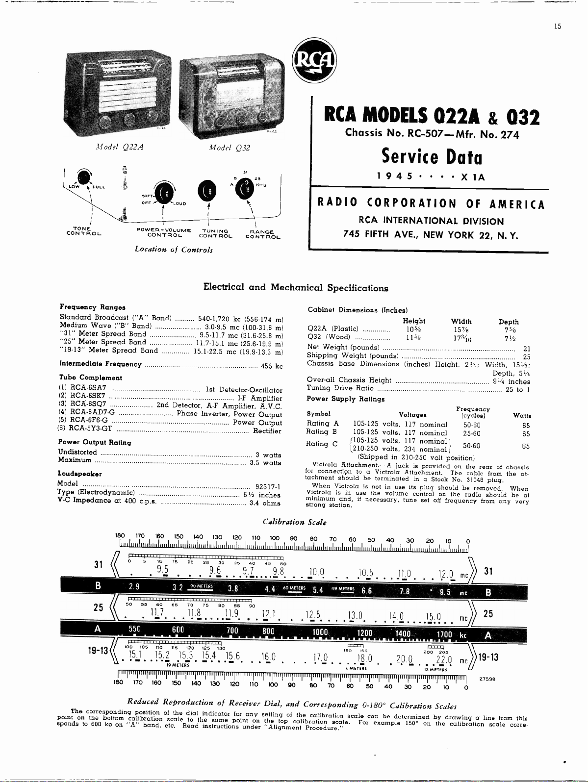
Model Q22A
LOW
TONE
CONTROL
SOFT
OFF
POWER -VOLUME
CONTROL
Location of Controls
Frequency Ranges
Standard Broadcast ("A" Band)
Medium Wave ("B" Band)
"31" Meter Spread Band
"25" Meter Spread Band
"19-13" Meter Spread Band
Intermediate Frequency
Tube Complement
(1) RCA-6SA7
(2) RCA-6SK7
(3) RCA-6SQ7
(4) ACA-6AD7-G
(5) RCA -6F6 -G
(6) RCA-5Y3-GT
Power Output Rating
Undistorted
Maximum
Loudspeaker
Model
Type (Electrodynamic)
V -C Impedance at 400 c.p.s.
Model Q32
31
61
25
A
19-13
LOUD
TUNING
CONTROL
RANGE
CONTROL
Electrical and Mechanical Specifications
540-1,720 kc (556-174 m)
3.0-9.5 mc (100-31.6 m)
9.5-11.7 mc (31.6-25.6 m)
11.7-15.1 mc (25.6-19.9 m)
15.1-22.5 mc (19.9-13.3 m)
455 kc
1st Detector -Oscillator
2nd Detector, A -F Amplifier, A.V.C.
Phase Inverter, Power Output
I -F Amplifier
Power Output
Rectifier
3 watts
3.5 watts
92517-1
61/2 inches
3.4 ohms
RCA MODELS 022A
& 032
Chassis No. RC -507 -Mfr. No. 274
Service Data
1 9 4 5
RADIO CORPORATION OF
RCA INTERNATIONAL DIVISION
745 FIFTH AVE., NEW YORK 22, N. Y.
Cabinet Dimensions (Inches)
Q22A (Plastic)
Q32 (Wood)
Net Weight (pounds)
Shipping Weight (pounds)
Chassis Base Dimensions (inches) Height,
Over-all Chassis Height
Tuning Drive Ratio
Power Supply Ratings
Symbol
Rating A
Rating B
Rating C
Victrola Attachment.- -A jack is provided on the
for connecti9n to a Victrola Attachment.
tachment should be terminated in a Stock No. 3104E1 plug.
When Victrola is not in use its plug should be removed. When
Victrola is
minimum and, if necessary, tune set off frequency from
strong station.
105-125 volts, 117 nominal
105-125 volts, 117 nominal
[105-125 volts, 117 nominal)
1210-250 volts, 234 nominal
(Shipped in 210-250 volt position)
in use the volume control on the radio should be at
Height
105/e
115e
Voltages
X
Width
151/2
17"i (1
Frequency
The cable from the
AMERICA
Depth
75S
71,1
23'4;
Width,
Depth, 51/4
91/4 inches
(cycles) Watts
50-60
25-60
50-60
rear of chassis
any very
151/2;
25 to
21
25
1
65
65
65
at-
180
170
160
150
140
130
120
31
25
A
11
0
5
10
15
9.5
=11
B
2.9
50
55
550
11111111111, 1,11 u.,,,111117
105
15.1
En
180
170
11.7
15.2
160
.41,1
60
110
3.2
65
600
115
19 METERS
150
17411
20
25
9.6
90 METERS
1111 ill 11111111
70
75
11.8
120
125
15.3
15.4
M
140
130
30
35
mi.
3.8
1...1
BO
85
11.9
_
700
130
15.6
m
120
Reduced Reproduction of Receiver Dial, and
The corresponding position of the dial indicator for
point on the bottom calibration scale to the same point
sponds to 600 kc on "A" band, etc.
Read instructions under "Alignment Procedure."
Calibration Scale
110
100
90
80
70
60
50
40
30
20
10
40
45
On
-
4,4
12.1
800
16.0
I=
100
50
9.8
60 METERS
90
10.0
5.4
09 METERS
12.5
eM=
1000
17.0
80
150
mi
16 METERS
70
13.0
FD=171
60
10.5
6.6
1200
155
18.0
11.0
7.8
14.0
1400
20.0
m.
50
40
30
'
15.0
12=1100
200
22.0
13 METERS
20
12.0
9.5
1100
205
10
9.7
90
110
Corresponding 0-180° Calibration Scales
any setting of the calibration scale can be determined by drawing
on the top calibration scale.
For example 150° on the calibration scale
0
31
me
mc
B
)
25
kc
19-13
mc
27598
0
a line from this
corre-
16
Q22A & Q32
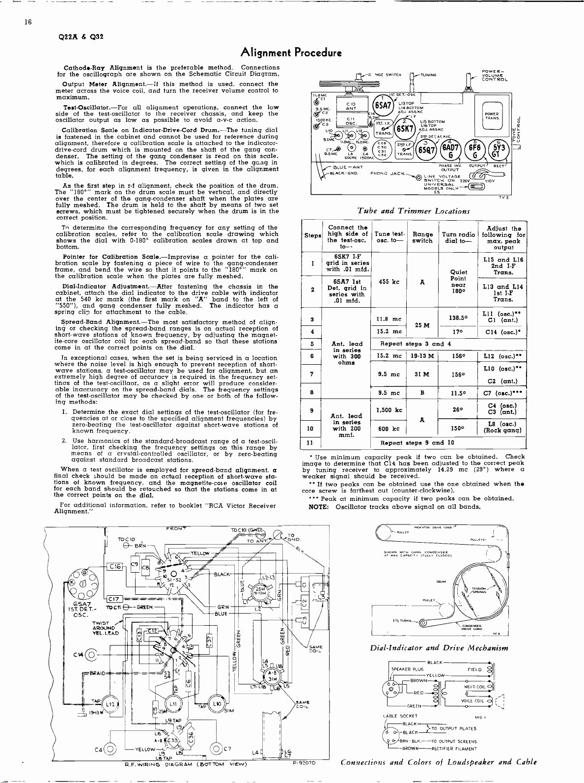
Cathode -Ray Alignment is the preferable method.
for the oscillograph are shown on the Schematic Circuit Diagram.
Output Meter Alignment.-If this method is used, connect the
meter across the voice coil, and turn the receiver volume control to
maximum.
Test-Oscillator.-For.
side of the test -oscillator to the receiver chassis, and keep the
oscillator output as low as possible to avoid a -v -c action.
Calibration Scale on Indicator -Drive -Cord Drum.-The tuning dial
is fastened in the cabinet and cannot be used for reference during
alignment, therefore a calibration scale is attached to the indicator -
drive -cord drum which is mounted on the shaft of the gang con-
denser.
which is calibrated in degrees. The correct setting of the gong in
degrees, for each alignment frequency, is given in the alignment
table.
The "1800" mark on the drum scale must be vertical, and directly
over the center of the gang -condenser shaft when the plates are
fully meshed.
calibration scales, refer to the calibration scale drawing which
shows the dial with 0-180° calibration scales drawn at top and
bottom.
bration scale by fastening a piece of wire to the gang -condenser
frame, and bend the wire so that it points to the "180°" mark on
the calibration scale when the plates are fully meshed.
cabinet, attach the dial indicator to the drive cable with indicator
at the 540 kc mark (the
"550"), and gang condenser fully meshed.
spring cliff for attachment to the cable.
ing or checking the spread -band ranges is on actual reception of
short-wave stations of known frequency, by adjusting the magnet-
ite -core oscillator coil for each spread -band so that these stations
come in at the correct points on the dial.
where the noise level is high enough to prevent reception of short-
wave stations, a test -oscillator may be used for alignment, but an
extremely high degree of accuracy is required in the frequency set-
tinas of the test-oscillaor, as a slight error will produce consider-
of the test -oscillator may be checked by one or both of the follow-
ing methods:
final check should be made on actual reception of short-wave sta-
tions of known frequency, and the magnetite -core oscillator
for each band should be retouched so that the stations come in at
the correct points on the dial.
Alignment."
The setting of the gang condenser is read on this scale,
As the first step in r -f alignment, check the position of the drum.
screws, which must be tightened securely when the drum is in the
correct position.
Tn determine the corresponding frequency for any setting of the
Pointer for Calibration Scale.-Improvise a pointer for the cali-
Dial -Indicator Adjustment.-After fastening the
Spread -Band Alignment.-The most satisfactory method of align-
In exceptional cases, when the set is being serviced in a location
1.
Determine the exact dial settings of the test -oscillator (for fre-
quencies at or close to the specified alignment frequencies) by
zero -beating the test -oscillator against short-wave stations of
known frequency.
2.
Use harmonics of the standard -broadcast range of a test -oscil-
lator,
first checking the frequency settings on this range by
means of a crustal -controlled
against standard broadcast stations.
When a test oscillator is employed for spread -band alignment, a
For additional information, refer to booklet "RCA Victor Receiver
all alignment operations, connect the low
The drum is held to the shaft by means of two set
first mark on "A" band to the left of
spread -band dials. The frequency settings
oscillator,
The indicator has a
Alignment Procedure
Connections
chassis in the
or by zero -beating
coil
a -c. NGE SWITCH
0.8
9 . ScivlaC
1500 SC
C3
LIO
9'SMC 11.8
3.5MC L8 C4
coons sop,
BL2'ALCUSE-G-NON. PHON 0 JACK
No
1.15 BOTTOM
LIE TOP
ADJ. 455 BC
EP SET, AE AVC.
PHASE
LINE VOLTAGE
SW ITCH ON
UN
MODEL. ONLY
OuTPVT
POWER -
CONTROL
POWER
TRANS.
OUTPUT
2204 1104
RECT.
Tv 2
Tube and Trimmer Locations
Connect the
high side of
Steps
the test-osc.
to--
6SK7 I -F
I
grid in series
with .01 mfd.
6SA7 1st
2
Det. grid in
series with
.01 mfd.
3
4
Ant. lead
5 Repeat steps 3 and 4
in series
6
with 300
ohms -
7
8
9
Ant. lead
in series
with 200
10
11 Repeat steps 9 and 10
image to determine that CI4 has been adjusted to the correct peak
by tuning receiver
weaker signal should be received.
core screw is farthest out (counter -clockwise).
mmf.
Use minimum capacity peak if two can be obtained.
** H two peaks can be obtained use the one obtained when the
Tune test-
osc. to-
455 kc
11.8 mc
15.2 mc
15.2 mc
9.5 mc
9.5 mc
Range
switch
A
25 M
19-13 M
31 M
B
1,500 kc
600 kc
A
to approximately
Turn radio
dial to-
Quiet
Point
near
1800
138.50
170
1560
1560
11.50 C7 (osc.)
260
-
1500
14.29 mc (29°) where a
*** Peak at minimum capacity if two peaks can be obtained.
Oscillator tracks above signal on all bands.
NOTE:
Adjust the
following
max. peak
output
1.15 and 1.16
2nd I -F
Trans.
1.13 and L14
1st I -F
Trans.
L11 (osc.)CI
(ant.)
C14 (osc.)
1.12 (osc.)
LIO (osc.)
C2 (ant.)
C4 (osc.)
C3 (ant.)
LB (osc.)
(Rock gang)
Check
for
6SA7
1ST. 06 T.-
CGC,
C141
r=BRAIDx =
TO C110
Twl5T
AROUND
YEL. LEAD
TAP
L12
173-751.1 -r-'
C4 2)
TOCIO
G- tmis
-7-
CI7
GREEN
11.1444:
-YELLOW
R.F. WIRING DIAGRAM
FRONT
tz,L:Amr,
-71
cL-p51
52
2
=
a
L9 L
Le TAP
r"7
( BOTTOM
LACK
GRN
BLUE
To CIO (GND)
IM
c
7
v7 )
TO ANT.
L2 LB
L4 E E;
D.
U
rr
z
SAME
COIL
CAME
COIL
L
P-92070 Connections and Colors of Loudspeaker and Cable
Dial -Indicator and Drive Mechanism
SPEAKER PLUG
LAKE SOCKET
0- -BLACK
BLACK
YELLOW
GREEN
BLACK
}TO OUTPUT PLATES
BRN-BLK.---TO OUTPUT SCREENS
BROWN -RECTIFIER FILAMENT
M5I

6AD7G
PH INVER.
& OUTPUT
230V.
C
NC
30V,
OUTPUT
n2v6Fe_G
R16
0
470,000
VOLTAGES SHOULD
WITH RATED SUPPLY.
HOLD WITHIN ±2.0%
e-0RN,RED-
TI
oR voL-rownys-r.
* MEASURED WITH
CHANALY5T
TOTAL
7003, TOTAL
BRN. -
BRN.
RECT SEATER S Y.
60N .
C2g
9.511G.
11.9i1
-RED
0-v .R
25, .7-
BLUE
SEATER 0.3V.
EBLUE_
-RED
CONNECTIONS
117V. POWER TRANS.
Ad-
Remove feelers
R12.
65Q7
2t9-DET-A.F-A.V.C.
2ND I. F TRANS
I.F
65K7
1.r TRANS
455 KC
1sT.
330,000
455 KC
r
90V
56
F'
-- `"
56'
C20
100
CIA
01
F UU
RI
c25
030
C),0
11
.C21
D
A
IS LI
C 24
C 38
470,000
.005
_
220
ioo
E
RE C 34 -r
22,000
RS
22.4E3
.05
R9
IS
500,000
TONE CONTRT
R 6
500,000
VOL. CONTR.
IC
.01
C 28
MEG.
IRViA°
PHONO.
%319
JAc K
TAP AT 125,000
R-7
12poo
/
4
15,000
A
C 32
05 c ILLOG RA PH CONNECTIONS
.035
C22 -
}B
KC)} A
05oosC)
VERTICAL." 0" TO CHASSIS.
VERTIcAl2 HI° TO THIS POINT,
-7V. (GOO
-
-BV. (9 MC)
-5V. (3 MC)
BAND)
(19-13
- 7V. (31 BAND)
-6V. (25 BAND)
- 5V.
292 V.
LIT
FIELD
RECT.
5Y3-GT
GRNrRED TR .
Ti
RED
LIZ
LII
100
63MA
300V 1060
GRI4.7 BED
I9 -13M
ac,
E+ 1 C30
+
Ct,279D.-:
BEN
4. 525a.
go TOTAL
RED-BLICI
12EOTAL
it i
BRN
5eE4
0 V
2203.
BLU.
I
-Es-EEDI
ONLY
SO ON Tv .
220v mOCD_S
sG
0-13
T -9319I
DIAL LAMPS
MAZDA *44
ELI) TO HEATERS
Loudspeaker. --
-
grga6,_
with repeated applications of acetone.
suspension
Keep acetone from flowing to other parts of the loud-
(Caution:
Keep the outer edge of the suspension soaked, and lift the cone,
To center the loudspeaker voice coil, first remove the dust cover.
Then loosen the center suspension by thoroughly soaking the outer
edge of this
Insert 3 feelers, equally spaced, between the voice coil and the
speaker.)
near the voice coil, up and down until the suspension is pulled
when cement has hardened completely.
away from the cone housing.
pole piece, arid allow the center suspension to re -cement itself.
ditional cement should be applied if necessary.
65N7
15T DE T- OSC.
TUBE SOCKETS
BOTTOM VIEW OF
A
G
232V.
MEG
C 3S
05
L az
S 33poo II
C17
SG
- An
isC87
CONNECTED
2- bo
CI -ANT
Li
=
35(1
CB
A
2-10
PR
C8
47
C9
GB
Le
I
(R53ua)
12
1 1 -C4930
RANGE SWITCH
VIEWED FROM FRONT
AND SHOWN IN 'A'BAND
(MAX. COUNTER C LOC K-
WISR ) POSITION.
C33-151
9
NOTE:
COIL RESISTANCE
VALUES LESS THAN
ONE OHM ARE NOT
SHOWN.
C4
2-12
(FRONT)
TERMINALS ON S3
TO CORRESPONDING
3 SA.
2-12
CIA
68
C13
C11
All oscillatbr coil leads must be kept apart from each other and
other leads and parts.
Blue plate lead of 2nd I -F transformer should be dressed under
All leads between antenna coils and switch must be as short as
possible and kept away from oscillator coil, leads and switches.
Precautionary Lead Dress. -
2.
1.
other leads and against chassis.
3.
NOTE.-On some sets C23 may be .0015 mf., C25 may be .0025 mf.
4siic)1

18
Q22A & Q32
Service Hint:
If minimum volume
reduced by dressing the yellow lead from hot
side of volume control (R6) away from the grid
coupling capacitor (C23).
Replacement Parts
STOCK
No.
Bracket-Drive cord pulley bracket complete with one (1) 30685
35640
35639
35622
37976
35642
12714
33014
34654
35646
36012
45465
70582
35644
39622
39632
70586
35645
39628
39636
70667
70687
70601 Capacitor-Tubular,
70624 Capacitor-Tubular, .003 mfd.,
70627 Capacitor-Tubular,
70648
70610 Capacitor-Tubular,
70631 Capacitor-Tubular,
70614
70615
70636 Capacitor-Tubular,
35631
35632
35623
35624
35625
35626
35619
35629
35620
32634
34662
12006
35788
31259
35627
35638
35641
35630
34761
30735
pulley
Bracket-Drive cord pulley bracket complete with three (3)
pulleys
Bracket-Flywheel support bracket
Bracket-Tone control support bracket 30652
Calibrator-Drive drum calibrator
Capacitor-Air trimmer (2-12 mmf.) (C4, C7, C14)
Capacitor-Electrolytic, consisting of three
10 mfd., 450 volts, and one (1) section of 20 mfd., 25 volts
(C29, C30, C3I, C32)
Capacitor-Mica trimmer, triple, 2.5-10 mmf, (C1, C2, C3)
Capacitor-Ceramic, 6 mmf. (C36)
Capacitor-Ceramic, 15 mmf. (C37)
Capacitor-Ceramic,
Capacitor-Ceramic, 47 mmf. (C8)
Capacitor-Ceramic, 47 mmf. (C12)
Capacitor-Mica, 56 mmf. (CI7)
Capacitor-Mica, 56 mmf. (C20, C21)
Capacitor-Mica, 68 mmf, (C9)
Capacitor-Ceramic, 68 mmf, (C13)
Capacitor-Mica, 100 mmf. (C15, C18, C34)
Capacitor-Mica, 220 mmf. (C16, C38)
Capacitor-Mica, 560 mmf. (C5)
Capacitor-Mica, 3000 mmf. (C6)
Capacitor-Tubular, .005 mfd., 1000 volts (C26, C27)
Capacitor-Tubular, .035
Capacitor-Tubular, .05
Coil-Antenna coil,
L2, L3)
Coil-Antenna coil, "A," "B" and 31 meter bands (L4, L5,
L6, L7, L18)
Coil-Oscillator coil, "A" and "B" bands (L8, L9)
Coil-Oscillator coil,
Coil-Oscillator coil, 25 meter band (L11)
Coil-Oscillator coil, 31 meter band (L10)
Condenser-Variable tuning condenser (C10, C11)
Control-Tone control (R9)
Control-Volume control and power switch (116, S6)
Cord-Drive cord (approx, 28 inches overall length)
Cord-Indicator cord (approx. 53 inches overall length)
Core-Adjustable core and stud assemblies for
formers
Core-Adjustable core and stud for "A" and "B" band os-
cillator coil
Core-Adjustable core and stud for 19-13 meter, 25 meter
and 31 meter oscillator coil
Drum-Drive drum less calibrator
Flywheel-Tuning knob shaft flywheel
Plug -4 contact female plug for speaker cable
5040
Pulley-Drive cord pulley
Pulley-Idler pulley located between the range switch and
tuning knob shafts
Resistor -10 ohms, 1/4 watt (R18)
Resistor -560 ohms, 1 watt (R15)
DESCRIPTION
CHASSIS ASSEMBLIES
RC -507
sections of
(3)
15 mmf. (C33) 31418
.002 mfd., 200
.005 mfd., 600
.01 mfd., 200
.01 mfd., 600 volts
mfd.,
mfd., 200 volts (C19)
.05 mfd., 600 volts
19-13 meter and 25 meter bands (LI,
volts (C23)
600 volts (C25) (T1)
volts (C24)
volts (C39)
200 volts (C22) STAMPED 92517-1J
(C28)
(C35)
19-13 meter band (L12)
I -F trans-
is too high, it
STOCK
No.
30436
35595
30492
30180
30493
14983
30648
30649
30992
14350
35633
35637
31364
14278
31251 Socket-Tube socket
12007
31261
35621
32827 Switch-Voltage switch (S5)
35636
35628
32852
35588
33726
2917 Washer-"C" washer for tuning knob shaft
70578 Cone-Cone and voice coil assembly
5118 Plug -4 -prong male plug for speaker
70583
70584 Transformer-Output transformer (T2)
35649
70579
35654 Dial-Glass dial scale
36658 Extension-Tone control shaft extension for Q32
35647 Frame-Dial frame complete less indicator
70581
X1611
70580 Indicator-Station selector indicator
35652 Knob-Range indicator knob
35651
35650
34489
11891 Lamp-Dial lamp (Mazda No. 44)
14270 Spring-Retaining spring for tone control, volume control,
4982 Spring-Retaining spring for range indicator knob
may be
DESCRIPTION
Resistor -12,000 ohms, 1/4 watt (I17)
Resistor -15,000 ohms, 3 watt (114)
Resistor -22,000 ohms, 1/4 watt (115)
Resistor -33,000 ohms, 1/4 watt (I12)
Resistor -120,000 ohms, 1/4 watt (1113)
Resistor-I50,000 ohms, 1/y watt (1114)
Resistor -330,000 ohms, I/4 watt (R12)
Resistor -470,000 ohms, 1/2 watt (R11, R16)
Resistor -1 megohm, 1/4 watt (R1)
Resistor -2.2 megohms, 1/4 watt (R3)
Resistor -10 megohms, 1/4 watt (R10)
Screw-:8-32 square head set screw for drive drum
Shaft-Range switch indicator knob shaft
Shaft-Tuning knob shaft
Socket-Lamp socket
Socket-Phono input socket
Spring-Drive cord
Spring-Retaining spring
stud assemblies
Spring-Retaining spring for oscillator coils' core and stud
assemblies
Switch-Range switch (SI, S2, S3, S4)
Transformer-First I -F transformer (L13, L14, C15, C18)
Transformer-Second I -F transformer (L15, LI6, C20, C21)
Transformer --Power transformer, 105-125 volts, 50/60 cycle
or 105-125/210-250 volts, 50/60 cycle (T1)
Transformer-Power transformer, 105-125 volts, 25/60 cycle
or indicator
cord spring.
I -F transformers' core and
for
Washer-"C" washer for idler pulley
SPEAKER ASSEMBLY
Speaker -61/2 -inch E.M. speaker complete with cone and
voice coil less plug and output transformer
Note: If
Back-Cabinet back for Q22A
Back-Cabinet back for Q32
Decal-Trade mark decal
Grille-Grille cloth for Q22A
Grille-Grille cloth for Q32
Knob-Range switch knob
Knob-Tone control knob
Knob-Tuning or volume control knob
stamping on speaker in instrument does not
agree with above speaker number, order replace -
ment parts by referring to model number of
strument, number stamped on speaker and full de scription of part required.
MISCELLANEOUS ASSEMBLIES
range switch and tuning knobs
in -
APPLY TO YOUR RCA DISTRIBUTOR FOR PRICES OF REPLACEMENT PARTS
Addition to Parts List under Mis-
cellaneous Assemblies:
for
Stock
Model Q32.
71083-Back-Cabinet
No.
back
 Loading...