


ffiRAFTjFEN
2-1/4 x 3-1/4 RB Series 8
Service & Parts Manual

2 1/4 x 3 1/4 RB SERHS 8 GRAFLEX
with REVOLVING BACK
TABLE OF CONTENTS
SERVICE INSTRUCTIONS SECTION
Front Door
TOp DOor
Front Plate
Body Parts
Bellows
Ground Glass
Ektalite Field Lens
Hood
Idler Frame
Mirror Frame
Release
Focal Plane Shutter
Disassembly
Clean and Lubricate
Reassemble, Adjust, Time
Revolving Back
Attaching Back
Slide Lock or Retaining Strip
Velvet - Revolving Frame
Wood Spacer Strips
Revolving Ring
Revolving Latch Back
Parts Catalog
Front Door
Top Door
Front Plate
Body Parts
Bellows
Ground Glass
Ektalite Field Lens
Hood
Idler Frame
Mirror Frame
Release
Focal Plane Shutter
Revolving Back
Stock Screws
Lubricants
Cement

-(..
2E X 3± R® a. Sel`ies 8 GRAFLEX
EE2QiE2Pg± !p±p_Ppp± , Front Plate
£p_ecial P±eQa_a_t±ons _f_Q±r=:
1. Front Door
i Panel
h Spring
iL covering
2. Top Door.
fu Replacement
h Handle
fu Brace
i Catch
fu Cover`ing
3. Front Plate
ji± Removal
h Adjustment
i Pinion Replacement
1. EiQp__t Door___(#_7_?=Z2±
fl lhe fl.ont door. (#777) is secured by three #0 x i" oval head wood scl`ews (#15280-4).
:§s:::i::::£§e::::w:::::ode:;a::::::g:i:::=:::k:§§::£::o::£:§C:i:;i.U=:±:S5b:°::c::::ry°r
h The panel spring (#8) is replaced by I.emoving hinge rod (#30172-P20). Position the
::Wt£:r:::±¥:?h ;£:Sc::Lt:;r±::±€:;s±'g:t:u:tp::e:::u:Ea¥o°£=f:ft::ep:::f ::p:::;: tension
Section 20A
Page 1
fi The cover.ing (#64-6) is secured to the
metal-panel.by cement and four rivets (#7329).
Use hot animal. glue or 3hi-EC-860 cement for
the lea.t`her covering.
i-inr-i
jL Io remove the top dool`, it will be neces-
sary to disconnect the I`ight and left brace
from the body--then, either. remove the hinge
rod (#30172-P21) or peel the leather from the
back and I'emove the hinge scI`ews.
Ihe serial number is stamped on the inside front edge of the top door. If this part
\f)
/I cut off excess
::p::€L:::i , t::eo::S::=e:e:h::Se:et:°£±:i::s::a::: :::p:¥:e:sa£:lie:s±8kErrfu :::u::I_
rect camera registration.
fat ¥£'gd::d`f|::33ingafe3:a::p::::gt:::ep:::::nif:::::in:ietE:v::p (.a:g59;5 ::in:g3?,., d2::ll
meter escutcheon pin, cut to length allowing a.bout i/16" above the washel' for I.iveting.
fu The top door 3::i:p::±g±trf€:€3{#Z§#.±3£:43r::ea:::¥b::: g::E :::e:of¥v:%:E:: E::t:t
to the ot]tside.
mnst inove freely.. .
a.. n.e::%.:5±d.:%:_%:.cg:.:_c.:.i:::s ::rL:¥:u3£et3;+i:€t±::I_t£::_%_:p£.gr t:.:_n_:.=.:g£33; , b_2€y.w±£±es; I f
necessa.ry to slide the anchol` plate back or forward respectively.
ti. The citeh..jl``t; (#12) will.requir.e that the leather be lifted along the front edge
for riveting. .File the.rivets flush on top before I.e-cementing leather..
• Re-form the. top.door .catch (#10), so tiat. the tension willbe against the body.
Pull to put tension
Bend off set and
J
On Spring
fr Th.e top door.covering .(#2275).intist be skived (sanded thin) at the edge.for easy and
Smooth cem.enting.
Ihe.:.ieath;r fl}a} be score.a witfi a .hot iron 1/8" wide on a line 5/8" from the edge.
Ihen score 1/16" .wide. on a line 1./4-" fr.om the adge.
Re.as;emble handle .and lugs--see paragl`a.ph fi
•,

Section 20A
Page 2
;.- a + .-.., ;
A,r.
L
J55TLr±3l=
•.J±2JiL-_-€]
j~rfeEL--=itH
r3EEEGLttH
fR!ffDIVo%fy:rr2:pav^
9055
.'giv
15183-8
1- I 5 9 6
FRONT PLATE COMPLETE NQ.15659

2± x 3i R. 8. Series 8 GRAFLEX
POP DOOR, FR0hTT
Section `20A
Page 3
l`f.: . .
\.3.
10
1|_P2
150814
15082-4.
15085-10
15180-3
15280-4.
15281-4-
15282-4
228
717 FRONT DOOR A5SE},BH
CAICH - TOP DOOR
Stl.ap - Top catch
Screw-hinge to body (i" #1 FT] S
Scl`ew - top door bl`ace to body
Scl'ew - Front plate to body
Screw - Top door strap to body
Screw - Front door to body
Screw - Top door catch to body
Screw - Focusing I`od bear.ing to
Hinge - Body section of top door
6 Door -front
8 Spring -fl.ant door
346 g::8:i;gf= °=:o:€°:oof
7329 Rivet - covering to front door.
30172-P20 Rod - front door hinge
2409 DOOR ASSEItBLY - TOP
12
13
17
288
3-P2 Rivet - catch plate to top door
114.20 BEARING T FOCUSING ROD
12696 COV£RING -FRONI
13659 .tmi ONI pinTL cohipLE.TL
Catch plate (Use I'ivet. #16599)
Lug - carrying handle
Washer - handle lug
Rivet - brace to top door
Cctvering -top door (}V;orocco Leather)
Brace assembly -top door, I.ight
Brace assembly -top door, left
Handle -camel`a Carry±nE.o65 diam. )
Rivet - handle lug
(use screw
(use screw
'' #2 FnTt I,17)
3" #5 FH S8)
(I.!ol'occo Leather.)
(Use screin/ #1528-4)
(hbrocco Leather)
_RT. L17)
L17)
QT¥. Unit cost
1.15
List
i.10
5.01
4. . 03
4.04
2.02
3.C|
2.03
3.01
i.30
i.90
15133-8 Screw - beal`ing plate (i" #3 RH L8)
!i:;6 ::::::a::::k:s::::i;n
114.22 Bearing plate - focusing rod
12700 Bolster block
12723 Focusing rod complete
13663 Catch Pin -door
30172-P2l R.od - top door hinge
11428 . Knob - focusing
12722 Focusing rod - complete with pinion
30663-PI Pin - focusing knob
Order by part number. and complete name. State quantity.
•. Prices are .subject to c.hange without notice.

Section 20A
Page 4
3. Front Plate (#13659).
#||Zg8?:n:E: f::a::::tr3Ea5:iri:gwi#lii85? ?gen::::!.:;:n::
(#||428) , the focusing rod bearing (#1142°) 9rE:: :::8:;P378* g .±±:tc£::Eaw.:38 ±::.:+sthe
front bellows frame sol.ew must be removed.
from the camera bottom to free the bc)lstel. block, and remove
(#13659)
2± x 3i R. 8. Series 8 GRAFLEJ£ .
Front Door., _TQp_ ___D__oQ__I=`„ FI`ont Plate
I.emove the focusing knob
th.e front plate..complete.
±seisi;s[#;g;55:o::dp:::e --
;;±=~;+ri/d;"{#ii536}`iovL[L.;_
move play. Check.tension
of yoke tension springs (#74.02).
Adequate tension Th-ill prever.t
f::g±ao: ±::gt::i::1:rE ::=¥.re_
quire incl`eased eff ol.t and
dissatisfied operation at
normal bellows extension.
fu Pinion replacement (#12722).
See paragraphs fu --there is no
short cut.

.---- f .
2± x 3i R. 8. Series 8 GRAFux
Body Parts
ipg.cial pre£Lautions for:
i. Bellows
2. Ground Glass and Ektalite Field Lens
3. Hood
4. Idler. Frame
5. Mirrol' Frame
6. Release
i Bello-ws (#7752).
i Remove thef font panel. Remove four #2-56 x i" oval head screws (10482-4.). At the
bottom of the rear. bellc>ws fl`ame, I'emove two #2 x i" I'ound head screws (#15182-4.). At the
top partition plate, loosen the three round head scl`ews and slide the bellows down and out.
h Inspect the front and I.ear bellows frame for flatness. Straighten if necessary.
fr Replace the back fl.ame by sliding t.he top beneath the partition plate. Reassemble
:E:n::t:::p::::Tl;::in:::np::#::: :?ed:::i::::ni E:::eo:c:i::;e.As;:::::in::: :::Sf:::t
fl.ame and position the threaded flange, so that the lens diaphragm index will be near the
top right.
2. Eoun££Llas±££=een As s±E±±1z__I (.£±3Q±Z_)___=a.pd_...T.F±_eld...LLe_P.a _.G±3±£.8±E3 ).
a. Assemble the serrations of the Ektalite field lens (#3188l-P3) to the ground surface
3f the ground glass (#13017) and bind the two opposed 3-1/16" long edges together with
papel' tape (#11504).
(i) Position the-asserr,bly with tape to the outside edges and the polished side of the
ground glass to the top.
(2) Bend the frame ears inward enough to hold the assembly. Do not attempt to bend
the ears down--it will crack the glass.
Section 208 .
Page 1
h Form the mounting tabs outwal`d to increase the sliding friction when focusing. Re-
assem`ole two #1 x i/4-" long round head sol.ews (#15181-4) at the back, and two special
machine screws (#118) at the front:
g. F.ocus as follows:
(i) Set lens wide open. Set camera f.ilm plane pal.allel and about 6 feet from a 4 foot
square target. Use pie charts ol. similar, or old calendar sheets having large and
small figures.
(2) Using a GRfiFLLX focusing panel, focus on film plane. Ijower mirror and adjust top
ground glass--check each corner and center.
(3) Check infinity focus using pro6edure of step (2). Tighten scl'ews when general
focus is satisfactol'y.
3. H=Q_Q€__±±_.a.sfnE,±I£J.#1271_€±.
If the. hood sags inwal.d and does not open fully at the top, an adjustment can be made by
lowering hood catch (#50). Plug old sol.ew holes and I.elocate.
•4 !..___I_.£±e_I..___E±ape._4.s=SLepb_ly. =£.#242£±. `.
The i.dler frame ass:mbly. is secured by fo.ur #2 x i/2" flat head wood screws (#150-2-8)--
two on eac.h side. '
• fie.in-eve-th`e b-a-c-k-; .-...-.
Mark .side index.of case and frame to assure co.rrect realignment.
•Lift fran.e .arid swi.ng .out at the top to avoid damage to the lower curved metal shieJ.dn
•... The lower idlel' should .turn free--lubricate.very lightly with graphite grease.
The. top idler. s.hould be staked to prevent .tul`ning and produce a quieter shutter.
Form metal shield, so. that it will not bind against the .tension roller and curtairl.
Replace squal`ely, and. be Sure .each aorner is pl`essed down tightly. If fl.ame is not square
or one side is h.igh,.. the cu.rtain ini.ght ride off to one side.

Section 208
Page 2
3,'= .
:--::=::-::::::-I:=__::---i:--::::::I--::
10645:
!N:.E2F2T68\, `t52--.- Z.-8.i
•.-Ni'i,,6±H3T€!
0-
: 7 7 5_2J
!~
ti §1- a 2 =_41
Jar§J
126:
-r3_.OJ_50;
(
`Li2.I
-`-. Ll.27-'8
-
'.
-i--:::--*-i:iiir---rfe_:i----:_--_--:ir_-:::-iif-:::-:---_-:
EffiHH EEi E=
.-
!l_!.T`.a_T±!
t
•iL52iir-:4J
.15ae+aj,
• '2i_2!
L2-±i!
2± x 3E R. 8. Series a GRAFIEX
BODY PARTS
Qty.
Section 208
Page 3
Unit Cost
List .
50
10482-4
122
126
150-2-8
15082-4.
151824
15182~4.
15281-4
232
24.8
Catch - hood
Screw - lens flange to front plate
Foot, Camera -forward
Pin - Name .plate to body
Screw
Screw
Screw
Screw
Screvi
Plate
plate
Block
Covering - CaJnera body
- Inside angle block
- tripod nut to c ase
- rear bellows frame to body
~ inside pal`tition plate
- bottom plate to body
-mirl.or frame, bottom
- bottom, rear
- lef t inside angle
Covering - back strip
Covering - front strip
IDLER FRAME ASSERE3LY
:;8:±=€ ::::i :t:::::o:t::Ei:: :i::¥d (3;8#L#FF£838j
220 Ijight shield - curve.d fol` tension I'oller
77rf2
10645
11434.
12158
12696
12718
16004-
30150
222
290
291
Top strip - inside idler fl`ame
Idler - bottom
Idler - top
Bellows asserubly
Plate - inside partition
Block - I`ight inside angle
Flange - lens .
Covering - fl.ont panel
Hood assembly
Tripod nut - bottom
Name and speed indicator plate
(Use screw #15281-4)
(±" #2-56 0H L17)
518
(Use screw #1528
(Use sol.ew #150-
(Mol`occo leathel`
(Morocco leather
(Morocco leather.
(Use scl`ew #150-2-8
(Use screw #15182-4)
(Use screw #150-2-8)
(Mor`occo leather)
(Use screw #15082-4)
Order by part numbel'.and complete name. State quantity.
•.PI.ices al`e subject to change withotlt notice.

Section 208
Page 4
-
15o .80-51,
24o7i tar"
•f-a:ir
245'
-TAPE ;
No.11504
©
- !1 lT6`5 i
ta-
15.2 81 -`4,
i-35TB o =3
L~
'T
•10 0 -2-4
i 2 2 § -6 0
L==
©£
.2285 2
ck.I
•1' 52 81 -4
a 255:
G-ROUND CLASS ASSEMBLY N5.13017'
®
•.I 0,6 4 5 .
a-- ,L5J±2_-4J
!2?i&9-
:"BRDR FRA"E.COMPLETE No.22803
.`',",,-"T,,,,,,fl!j,,,':,iapl,ap,,,,,,,,,,,
.€_2_9 5
[I,l!,ill,;,;
2289

2+- x 3f R. 8. Series 8 GRAFIIEjt
GROUND GRASS, ELI.iAsh, hREOR FRch4E
Section 208
Page 5
-If..-.
13ol7 Gi{uuND GLesD scELjn' A3sLIiBLr
2g36 g:=: : g::::: :::::nscreen
11504. Tape -scl`een edge
3188l-P3 Field Lens - Ektalite
14.278 REhASL IEvjiR - iflRROR FRch{E
:::Z8 i;:::8:I::::::::::::Se lever plate
228o3 hilREOR Ffich:a c ompLETh`
i:i ::;::-;:lF::::;:::i!:t::;::e
§§§§ i;i::::::::1::::i:=:I:::::::::Et i:::::::I:::::;side)
24.07 Lever - mirrol' set
24.2C Hirror frame assembly (Ordel` covet.ing #2287 a #2288)
loo-2-4 Screw - mirl.or frame to rod
205 hiirl'or frame
263 Rod -mirror frame
34.
96
118
15080-3
15180-3
15181-4
i5nel-4
i2431
1064-5
1116 5
22852
Spring - mirror fl`ame lif ting
Plate - mirl`or frame beal.ing
Screw -.ground glass scl`een assembly to body
Screw - mirror frame beal`ing 'plate to body (3/16
Screw - inside frame to body
Screw ~ ground glass scl`een assembly
ScI.ew - mirror frame plate to bod}r
Scl`ew - inside par.tition plate to body
Scl`ew - release level` to body
Screw - bushing container tc` body
Plate -mil`ror fl`ame, bottom
Inside fl.ace
Bushing container -for. rod and spring.
I & I s.lide assembly
Plate - inside par.tition
Light break for I'elease
Light bl'eak - mirror f fame I.6d
(Use screirs #113 i #15181-4) i
(Order 2 of #11504-)
(Use screw #15281-4)
(Use screw #15080-3)
e screw #15181-4-
e screw #15080-3
e screw #15281-4
(Use scl`ew #15182-4)
(Mohair)
7)
'=.ty' Unit cost
List
i
i.50
.50
i.00
.01
Qrdel. by part. number and complete name. State quantity.
. Prices are .subject to change without notice.

Section 208
Page 6
2+ x 3± R. 8. Sel'ies 8 GRAFI.FX
Body Parts
i_ ___ng±r_rQr ____F_ra_fpe (#?2_8_Q3±.
a. Mirl.or (#229
5i#5!5|::;::::ment
h Frame.spring
fr Frame complete (#22803) replacement
fu Hil`ror (#2295) replacement. ..
(i) |t will be convenient to I.emove the hook::gn8L9::Erg:i:;.::r=:; (£i±85a::8:::h 2
and 3. Set focal plane ctirtain open.
clip.-Remove two mirl'or Clip screws from 6ther .clip; I`.emov§ this clip, and then
remove the mirror.
(2).Patch the mirror frame covering, if torn when .re.moving. a cem.ented mirror..
(3) Insert the new mirror with first-surface up.. Replace mirror frame clip; tighten
screws. Reassemble ground glass and refocus--see paragraph.2 .e+ a.fol`enentioned;
i Frame spring (#34) I`eplacement.
Apply spring tension by ttil.ning mirror. frame spring container.. (#262) c.lockwise.
Enough tension should be applied to lift the nirrc>r, but it must not be tog much aha
cause camel.a movement.
c. Frame cc>mplete (#22803) replacement.
Disassembly.
(i) Remove hood and ground glass. Remove mirror set lever (#2407) th.at is secured
by a taper. pin (#120).
t#34.j. From frame and I:::o¥:in:::I:£r.::a#;_;gr±nE„c:£::±£::dt¥:f:*saE£L88:±:E,.
(2) Ihe back covering (#2286) of trie mil'ror frame is cemented to the light shi6ld
(#220) of the idler frame asseITlbly. Remove carefully--do not teal'.
Reas{:Tb5¥;an old cement from the ap|`on of the mirror frame. back covering. Reassemble
.
{;ggg325:ds#::3 , {#jz5:w:n£#:S£=:;4: :n¥:=::: {;E6±3Terc:#::%7tAeL:g::nb::t¥ EC.88o
cement or rubber cement.
(4) Replace gI'ound glass and focus--see pal`agraph 2 i
£Lje±?Tas±I£3££±J±E±42ZEl .
fr the release lever is. secured witfj f our #0 x ±" oval h.ead
screws (#15281-4). Check the mohaiI' light break (#11165)--
dust or replace.if matted. Ihe mirl.or I.elease arm must be
positioned in relation to the mirror. as sketched.
•Since the mirl'or depression may be changed when the re-
lease lever is replaced, it is necessal`y to che.ck focus--
see pal.agraph 2 gL

2± x 3± R. 8. Series 8 GRAELEX
Focal Plane Shutter
Section 20C
Page 1
SDecial Precautions for:
i. Disassembly
jit Shutter setting plate
h Tension setting plate
2. Clean and Lubricate
3. Reassemble, Adjust, Time
jL Curtain and Rollers
i. Disassemfty.
jL Shutter setting plate (#12724.) is secured by f our #3 x
NOTE: Screw in forward top plate hole is cut off to.3/
Remove the mil'ror lever assembly
The illustration does not show the outside f.ace--see
" oval head screws (#15283-8).
„ long.
g
the parts layout on. Page 2.
h Tension setting plate (#14-231) is secured by four #3 x i" oval head screws (#15283-8).
Io replace the tension pawl spring (#14227), it may be necessaLI.y to remove the riveted
tension winding knob (#14228). In this case, supply new knob.
*he :::£¥:sr:I:±V3£EE8=896 :3£e§:%:ton 2°D. the Curtain assembly-(#242i) -i-s cemented to
roughe.n brass tube for adhesive tooth.Use C°az'Se Sam.qpaper I.O.I.9F.oy?. olq 9.?Ipent apd
The axis of the roller must be cemented squarely to the longitudinal dimension of the
cul`taino Failul'e to do this will cause the curtain to roll to one side and bind against
the camera body. Remove rollers from the camera to be assured of the best alignment when
I ec eme nti n g .
0 0
TT---
The gear roller assembly (#24-18) must be removed after the idler assembly has been re-
moved. Mal'k side index of case and frame to assure col'rect I.ealignment. Lift fl`ame and
swing out at the. top to avoid damage to the curved metal shield.
The tensic>n rolle.r assembly (#14251) must be.removed through the bottom of the camel`a.
Remove the bottom plate (#24-8) that is secured by eight #0 x i" ova.i head scl`ews (#152814]
2. Cleaning and Lubric.ation. .
i Clean all metal p.arts by. immel`sing in cleaning solvent. Wash thor-oughly to remove all
d.i|`t and foreign matter. All par.ts should b e dry before I.eassembly.
h Lubl.icate as follows:
I±§E _I_Q C _a ±± Q_LB_
EScapement Spring . .Lubricate area tha.t. opel`ates with master gear #107 Lubriplate
Lubr i c ati on
s:::=ngs I:E=:::::p:::i::gbga:=ng:a:€. each end. %::EE±:: ::: a::::: #3
Springs Dip. springs for rust prevention and ligbt Singer Sewing Machine
CAUTI0H: I,ubricate .moderately. Do not allc>w. any lubrication to contact the rubber. of the
lubricati.on. Oil
shutter curtain.

Section 20C
Page 2
1-g155,,
Hit ffi
„*3-a
a_06
I 3- 0 I 3
163---pZ
; LEVER :
iNo. 2 4 0 7
--,
1L±231
2± x 3± R. a. Series a GRAFLEX
FOCAL PLANE SRTTTER
Section 20C
Page 3
i.`.-
24.18 GEAR R0I.LEE AS5EREI;Y
24.21 CURTAIN ASSREI,Y
12724. SHUTTER PIAIE com>IEIE
j!i;i i§:#€:::i¥i::::::i:i:::Sse lever
30663-P2 Pin - winding key a focuging kdob
14.231 TENsloN PLATE COMPLETE
:::2g :;:::; :e;::::::i;:I::se pawl
14.251 rEh'si oi¢ ROLhiR Assrfu.BI,I
260 Spring -tension. roller
15081-3
15BO-4
15283-8
152j33-8
153
221
267
24.07
2431
6551
17077
Screw' - gear. roller light shield
Screw - gear roller light shield
Screw - tensioh plate to body
Screw - shutter plate to body
Nut -tension plate roller bushjng
Light shield - gear roller
Bearing - cul.tain I`ol.Ier
Lever -.nil.For set ,
I a I slide assembly
.rack - oul`tain guard to body
Gual`d - curtain
(3/16" #1 FH S8)
(a" #0 RH S8)
(±„ #3 0H L17)
(i„ #3 011 L17)
(Use scl`ew #15081-3 & #15180-4.)
Qty. Unit cost
List
2.50
4.25
7.50
.05
.07
.05
4.25
.10
.10
.45
3,00
.45
Order. by.pal.t number and complete .none. State quantity.
Prices. .al`e spbject to change v,Tithout notice.
Section 20C
Page 4
2± x 3± R. 8. Series 8 GRAFLEX .
Focal Plane Shutter
i+___Reass_epple,__fld.iust+I__E±_PL§.
fu The axis of the roller must be cemented squarely to
curtain. Failul.e to do this will cause the curtain to.
the camera body. Remove rc>llers from .the camera to .b.e
I.ecementing.
the. lop.gitud.inal di-.men.sion of the
roll to one side .and:bind against
assul.ed .of th.e best..alignment when
Lubricate curtain roller beari.ngs and replac; assembly. . .
h Replace the idler assembly--form shield s.o :that it does..not .bind .against t.ensi.on
roller. . Align the assembly square with the camera body..
g+ Lubricate the shutter plate--see paragr`'iph 2 h Position the stop .pi.ns as shoyn...in .
paragraph 1 a„ indicator gear mst be centel`ed. on ''0''. , .
i Align the open slit of the ctntain so that its top strut is .over the top idler.. .
Positic>n the shutter plate.
j2± Position the tension plate set at "1''. Wind the tension knc)b a .flew times. Operate
the shutter to remove curtain slack. Check interference at-the.idler shield.
...
i Setting tension: Hold slotted tension shaft with screwdl`iver thr.ough hole in tension
B::::ionR::::=:nt;::::na::°#:¥du::i:6:+i ::±:i ::n::o:e:::£eg;rex:::v:i?Li:f€ ;±a::"and
turn knob to ''l't; lower. plate and assemble screws.
jL Setting curtain: Ihe top stl.ut of open aperture must not drop below the top idler.
f{aise or lower one tooth of the gear. roller; or, finer adjustment nay `De made by adding
or I'emoving cur.tain material at the gear roller to change the diameter. Check curtain
struts at all apel.tunes--watch for bounce at bottom. Corl`ect bounce by checking latch of
shutter plate escapement and master gear s top pinsi or, it may be necessary to lower the
strut by changing gear I.oller mesh.
a
Cement curtain additiona.I by dropping past '`0" to latch. Draw a pencil line down the
center of the roller. Ihis line will show inside, apply.3m-EC-880 adhesive above this
line. Repeat at the bottom.
-~,
2¥ x 3± R. a. Series a GRAFIEX
Biv_p lvi n g _ _P_e=j2¥
Section 20D
Page 1
Special PI.ecautions for:
Attaching Back to Camera
(
Sliding Lock or Retainer Stl`ip
Velvet
Wood Spacer Strip
Revolving Back Ring
Revolving Back Ijatch
li___ ___Attach±_pg___Back to Camera.
Ihe revolving back (#24.25) is attached to the
Camera body with eight #1 x ±`' flat head wood
scl`ews from the back and three #1 x i" oval
head wood sol.ews from the side.
LS|i di ng _I Qcl€ . _ i.{._#? 7J.. _ Q_I_ _ Re ta±±±±ngj±±±_i.p i_#2Z±J .
i The sliding lock (#27) is secured to wood
S8:::: {#;EB£¥£3:9) by two round head wood
h The retaining strip (#273) is secured by
four rfl x z'. oval head wood screws (#15281-4-)
to wood spacel` stl'ip (#2269).
L]I±±.Iret I._ =Fej[Q_lvinj3 F=g±p_e _ (.#?=Z5£2.
fr Heir.ove the wood spacer strips (#2269). See pal`agraph beloiF.
h Remove old velvet and cement. Use 3H-EC-880 for. the new velvet.
CAUTION: Do not saturate the velvet i^rith the adhesive .... it willdestl'ey the plush
texture. II.in loose threads around the opening.
4+ _ ngoo_d___=SpLa_Qe_r St_I_ip (#2?6_2)=.
%re::e.t#£;gB£:a;e:n3tf:8mL:h:e%::=dbfrto#o t#= £u5;±g: :£g: £¥aEwfo€± =c±,:w:vE±L38%£.¥;::..
I'evolve the frame as illustpated for access to the back scl.ews.
h If the wo.od spacer is r eplaced, it will be necessary to perfol.ate new holes for the
scl`ews. Reassemble the back screws fit.st.
i____a_ev.ol_¥±ngEapk..Ring_I_rf2_E§J.
i The I'evolvi.ng back ring (#258) is secured by eight special flat machine scl'ews. Re-
move wood spacer strips and velvet from revolving fl'ame for access to screw heads.
• h Lubricate the bearing surface vel.y lightly with #107 I.ubriplate -or Parawax.
•.,
fu .Reassemble rin.g screws .... tighten to equal tension. Check I`evolving operation. See
paragraphs 3 and 4 above for velvet and spacer strip replacement.
£tuLevc>1viQLg__Ea__c_*___Latiqut.
¥e :::.e::¥°±¥±:Eeb:::n±:::hf::::in::¥e.::i;L{#:gz}?ed On Page 2 of this section. All pal.ts
h The latch lev:r .(#256) should be flat and have the inside stirface lubricated.very
lightly with rfl07.Lubl.iplate or Parawax. If.necessary, file latch s.top _to fit _I.ing notch.
fr Noti.ce required ri.vets mentioned in pal.ts listing when ol`dering I.eplacements.

Section 20D
Page 2
~,
. _ . _ ,--..- ;
?H3-
®
•....
;L:2i!
¥.[l_50-a--i3]
•!£-E'6-9;
:FTBAfaLEAs~s_EinBL7NQ-fo66Oj
i i.,ji-zTffl¥:
;±i3l`:. t
..a.
.i_5ZLj2t4
~,,.a~r.+:...:..,.`.;..`,...._.<`..-.!E£~CK`.C.gee,.E±E.IE.¥.?..24?i.5.I.-i_:.::...._~,..w....`.::.i....:i.,.`
*
+
__---.----.--.--'.-

2¥ x 3± R. 8. Series a GRAFIEX
REV0IjvING BACK
Section 20D
Page 3
24.2 5
REVo|,i.riNG BACK CoMPRETE
27 Lock -sliding
119 Screw - ring to I`evolving frame
(Order attaching screws)
(Use scl'ew #15182-4)
:g:::i ::::; : ::::e::.;:: :: I:;::;:::p::::: (:#: a ::7;8)
±5:BL_4 §::e¥ =L:::a±::Ego:::::i:: Wood
258 Ring -I.evolving back
273 Strip -plate holder retaining
304 FI`ame assembly -mounting
:87 #::::I--i::::ai:v::ung er
178 Plunger -release
256 Level` -latch
257 Spring -latch lever
30363-P6 Rivet - latch lever spring
2258 Velvet -revolving frame
2269 Strip -wood spacel`, I`evolving fl`ame (Use scl`ews #15081-3 &
10660 Frajne assembly -revolving
259 FI.ame -I`evolving
2399 Felt.-revolving frame
Attaching screws - revolving back to body
15081-4.
15281-4
Scl`ew - revolving back to body
Screw.-I`evolving I?ack to body
strip (i" #1 OH L17)
(Use screw #15281-4)
#15281-4)
(±„ #1 FH L17)
(±„ #1 OH L17)
Qty. Unit cost
i 9.85
Z
I.ist
i
i
i
30
Ofdel' by. part nun'ber.and complete name. State quantity.
`.Prices are .S.tibject to change.without notice.

!,
i
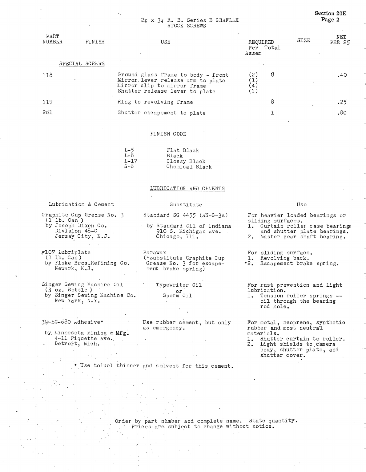
• Section 20E
Page 1
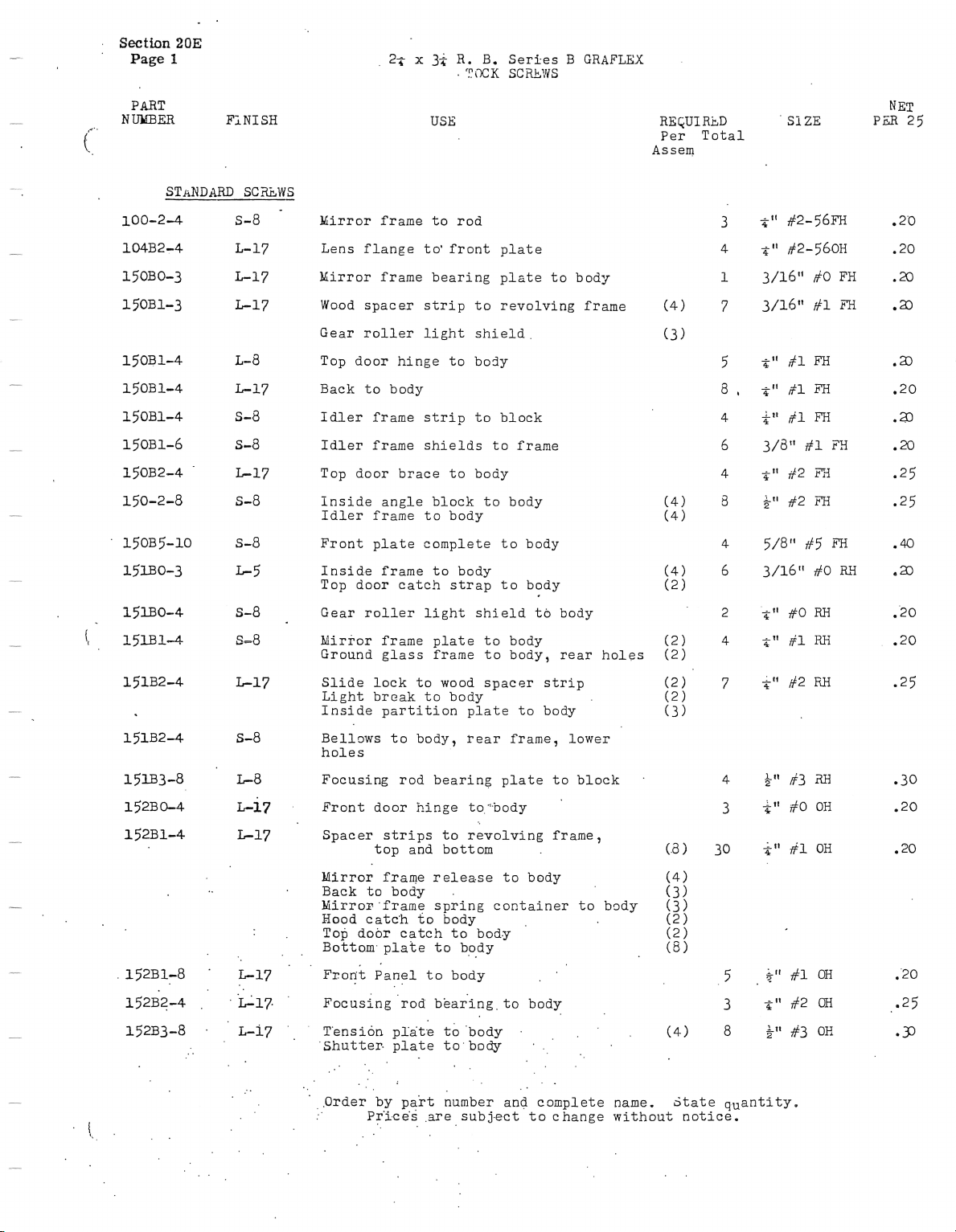
2Tf x 3± R. 8. Seri-es 8 GRAFLEX
. r.T\TX=K SCRLtws
PARI
NURERE
STANDARD SC^ELWS
FiNISH
loo-24 S-8
10482-4.
15080-3
15081-3
15081-4. I-8
15081-4 L17
15081-4. S-8
15081-6 S-8
15082-4 L17
150-2-8 S-8
• 15085-1o s-8
151BO-3 L5
15DO-4 S-8
{t 15lB ltd s-8
USE
Hirl-or frame to rod
Lens flange to` front plate
Mil`ror fl.ame bearing plate to body
Wo.od spacer strip to revolving fl`ame
Geal` roller light shield.
Top door hinge to body
Back to body
Idler frame strip to block
Idlel' fl`ame shields to frame
Top door brace to body
Inside angle block to body
Idler frame to body
Front plate complete to body
Inside frame to body
Pop door catch strap to body
Gear I.oller light shield t6 body
mirior frame plate to body
Ground glass frame to body, rear holes
RBQUIRLD
Per. Total
Assem
' SIZE
¥„ #2-56FT
a" #2-56OH
1 3/16„ #O FH
7 3/16" #1 rH
5 €„ #|FH
8 . i " #1 t"
4. ±„ rfl FH
6 3/8„ #| FH
±„ #2 Fi
i„ #2 FH
4- 5/8" #5 rH
(4) 6 3/16" #O R+i
(2)
2 ir" #O RE
4- ±„ #1 RE
NEI
Pm25
.2'0
.20
.20
.2D
15182-4. L17
151824
151B3-8
152Bon4
15281-4-
. L52BL_8 I.]7
1528.2-4 . .L17.
15283-8 I-i7
•(
Slide lock to wood spacer strip
Light bl'eak to body
Inside partition plate to body
Bellows to body, rear fl`ame, lowel`
holes
Focusing rod bearing plate to block
Front door :h.inge to<.body
Spacer strips to I`evolving frame,
top and bottom
Llirror fraH}e relea.se to body
Back to body
nil.ror..frame spring cop.tainer to body
Hood ca.tc.h to body
Pop door catch to bod.y
Bottom. plate to body
`®
Fron.t Panel to body
Fc>cusing rod. b.ear.ing. to body
I.ensi6n pl.a.t.e t6 .body .
Shutter. plate to.body
.Order by p.art number anQ complete name. State quantity.
Pr.i.ces .are subs-ect to change without notice.
7 iM rf2 RE
4- £0 #3 RE
3 ±„ #00H
±„ #1 OH
2± x 3+ R. 8. Series 8 GRAFLH
STCCK SCREWS
Section 20E
Page 2
PART
IiunebR
SPECIAL SCELWS
118
Lubl'ication ck Cement
GI'aphite Cup Grease lv-o. 3
(i |b. Can )
by u-oseph Jixon Co.
FI N I SH
Division 45-C
Je.rse-y City, It`.J.
®
USE
Ground glass fra.me to body -front
hill-I'or. lever release arm to plate
A:irl`or clip to mirror frame
Shuttel' release lever to plate
Ring to revolving fl.ame
S.hutter escapement to plate
FINISH CODE
L-5
L-8
L-17
S-3
Flat Black
Black
Glossy Black
Chemical Black
LtJBRICATI ciELAI{D CE!,iENTS
Substitute
Standal'd SG 4-455 (AN-G-3A)
. by Standard Oil of indiana
910 S. I:iGhigan j+ve. .
Chicago, 11.i.
RE QUI RD SIZE
Per Total
Assem
Use
For heavier loaded bearings or
sliding surfaces.
i. Curtain I`oller case bearings
and shut,ter. plate bearings.
2. hiaster gear shaft bearing.
NET
PER 25
ff{!7L5-:b::E])at'e
by Fiske Bros.j{efinir.g Co.
h.e'`vark, I\..J.
Singer Sewing h.:ac]Ljir;e Oil
(3 oz® Bottle )
by Singer Sewing hiac!i.ine Co.
Itlew tlol'k, I\'.Y.
3E`-LC-580 Adhesive*
by. hiinnesc>ta kining a Mfg.
4-11 Piquette Ave..
•. Detroi.t., haich.
I Use toluol t+fiiinnel. and solvent for this cement.
Parawax
(*Dubstitute GI`aphite Cup
Grease No. 3 for escape-
merfe brake spl.ing)
TypeTuriter Oil
Or
Sperm Oil
For sliding surface.
i. Revolving back.
*2. Escapement brake spring.
For I'ust prevention and light
ltlbl`i c ati on ,
i. Tension roller springs --
oil through the bearing
rod hole.
Use rubber cement, but only
as emergency.
For metal, neopl`ene, synthetic
I'ubber and most neutra'l
materials.
1. Shutter curtain to roller.
2. Light shields to camera
body, shutter. plate, and
shutter cover.
OI'der by pal`t ntimb;I and complete name. State qtiantity.
• Prices.are subject to change without notice.

-.
i. _ _I
-__:
e=
i-.'
-__+
.---.
I_ - - -I
T=_-
:__ _ L
`,-.
'`

GRAFI.EX, IHc.
Main Offices and Factories:
Rochester 8, N® Y„ U. So A®
Eastern Service Offices:
50 Roe.kefeller Plaza, Suite 922
New York 20, N.Y.
western mvi8ion:
3045 Wil8hire Blvdo
•Lo8 AngeleB 5, Calif
 Loading...