

RBI FB series, FW series, FUTERA II FB series, FUTERA II FW series Installation & Operation Manual
FTII-IOM-5
FUTERA II SERIES FINNED COPPER
GAS BOILERS (MODEL FB) &
WATER HEATERS (MODEL FW)
INSTALLATION & OPERATION MANUAL
DESIGNED AND TESTED ACCORDING TO A.S.M.E. BOILER AND PRESSURE
VESSEL CODE, SECTION IV FOR A MAXIMUM ALLOWABLE WORKING PRESSURE
OF 160 PSI,
WARNING: If the information in this manual is not followed exactly, a fire
or explosion may result causing property damage, personal injury or loss of life.
Do not store or use gasoline or other flammable vapors and liquids in the vicinity of
this or any other appliance.
WHAT TO DO IF YOU SMELL GAS:
• Do not try to light any appliance.
• Do not touch any electrical switch. Do not use any phone in your building.
• Immediately call your gas supplier from a neighbor’s phone. Follow the gas
supplier’s instructions.
• If you cannot reach your gas supplier, call the fire department.
Installation and service must be performed by a qualified installer, service agency or
the gas supplier.
WARNING: Failure to properly vent this unit can cause excessive amounts of carbon
monoxide resulting in severe personal injury or death!
1103 kPa
, WATER.
INSTALLER, THESE INSTRUCTIONS TO BE AFFIXED ADJACENT TO THE BOILER / WATER HEATER.
CONSUMER, RETAIN THESE INSTRUCTIONS FOR FUTURE REFERENCE PURPOSES.
260 North Elm Street 1300 Midway Boulevard
Westfield, MA 01085
Phone: (413) 568-9571 Phone: (905) 670-5888
Fax: (413) 568-9613 Fax: (905) 670-5782
Mississauga, Ontario L5T 2G8 Canada
www.rbiwaterheaters.com

FUTERA II INSTALLATION AND OPERATION INSTRUCTIONS
AVERTISSMENT. Assurez-vous de bien suivre les instructions données dans cette notice pour
réduire au minimum le risque d’incendie ou d’explosion ou pour éviter tout dommoge matériel,
toute blessure ou la mort
Ne pas entreposer ni utiliser d’essence ou ni d’autres vapeurs ou liquides inflammables à
proximité de cet appareil ou de tout autre appareil.
QUE FAIRE SI VOUS SENTEZ UNE ODEUR DE GAZ:
• Ne pas tenter d’allumer d’appareil.
• Ne touchez à aucun interrupteur; ne pas vous servir des téléphones se trouvant dans le
bâtiment.
• Appelez immédiatement votre fournisseur de gas depuis un voisin. Suivez les intructions du
fournisseur.
• Si vous ne purvez rejoindre le fournisseur, appelez le service des incendies.
L’installation et l’entretien doivent être assurés par un installateur ou un service d’entretien
qualifié ou par le fournisseur de gaz.
CONTENTS
Before Your Start ................................................. page 2
Ratings & Capacities ...........................................page 3
Boiler/Water Heater Location ..............................page 3
Combustion Air & Ventilation............................... page 3
General Venting Guidelines .................................page 5
Outdoor Venting .................................................. page 13
Common Vent Systems .......................................page 14
General Piping Requirements .............................page 14
Heating System Piping ........................................ page 16
Domestic Water Supply Piping ............................ page 20
Gas Supply Piping............................................... page 24
Electrical Wiring .................................................. page 25
General Operation............................................... page 25
Operating Instructions .........................................page 25
Checking & Adjustments .....................................page 27
Control Description ............................................. page 29
Diagnostics.......................................................... page 30
Maintenance........................................................ page 31
Trouble-Shooting ................................................. page 33
Repair Parts ........................................................ page 34
Start Up Sheet .................................................... page 41
BEFORE YOU START
This manual covers the application, installation, operation
and maintenance of a Futera II Series finned copper
heating boiler/water heater/pool heater.
To obtain the safe, dependable, efficient operation and long
life for which this heating boiler/water heater was designed,
these instructions must be read, understood and followed.
The Futera II Series finned copper heating boiler/water
heaters have been design certified by CSA for use with
natural and propane gas under the latest revision of ANSIZ21.10.3/CSA 4.3, Gas Water Heaters, ANSI-Z21.13/CSA
4.9, Gas-Fired Low Pressure Steam and Hot Water Boilers
and CAN1-3.1, Industrial and Commercial Gas Fired
Packaged Boilers. Each unit has been constructed and
hydrostatically tested for a maximum working pressure of
160 psi,
A.S.M.E. Boiler and Pressure Vessel Code.
All aspects of the boiler/water heater installation must
conform to the requirements of the authority having jurisdiction, or, in the absence of such requirements, to the
National Fuel Gas Code, ANSI Z223.1/NFPA 54-latest
revision. Where required by the authority having jurisdiction,
the installation must conform to the Standard for Controls
and Safety Devices for Automatically Fired Boilers, ANSI/
ASME CSD-1.
In Canada, the installation must be in accordance with the
requirements of CSA B149.1 or .2, Installation Code for
Gas Burning Appliances and Equipment.
If installed in the Commonwealth of Massachusetts, you
MUST FOLLOW the additional instructions contained in
RBI’s instruction sheet MACODE-1. If you do not have a
copy, call your RBI distributor or contact the RBI Customer
Service Department.
The owner should maintain a record of all service work
performed with the date and a description of the work done.
Include the name of the service organization for future
reference.
Direct all questions to your RBI distributor or contact the
RBI Customer Service Department at: 260 North Elm
Street, Westfield, MA 01085 for US or 1300 Midway
Boulevard, Mississauga ONT L5T 2G8 for Canada. Always
include the model and serial numbers from the rating plate
of the boiler/water heater in question.
1103 kPa
in accordance with Section IV of the
2

FUTERA II INSTALLATION AND OPERATION INSTRUCTIONS
RATINGS & CAPACITIES
Before undertaking the installation of the Futera II Series
boiler/water heater check the rating plate to ensure that the
unit has been sized properly for the job. The “Net I=B=R
Ratings” specify the equivalent amount of direct cast iron
radiation that the unit can supply under normal conditions.
Also ensure that the unit has been set up for the type of
gas available at the installation site. Other important
considerations are the availability of an adequate electrical
supply, fresh air for combustion and a suitable chimney or
vent system.
BOILER/WATER HEATER LOCATION
1. This boiler/water heater is suitable for indoor and
outdoor installations. Locate the boiler/water heater in
an area that provides good access to the unit. Servicing
may require the removal of jacket panels. Allow the
minimum clearances between adjacent construction
and the boiler/water heater as listed in Table 1.
NOTE: Service clearances are not mandatory, but are
recommended to ensure ease of service should it be
required.
Table 1
Clearance to Service
Combustibles Clearance
in
To p 24
Back 14
Left Side 6
Right Side 6
Front 8
2. An optimum site will be level, central to the piping
system, close to a chimney or outside wall and have
adequate fresh air for combustion. Ensure that the
boiler/water heater is level from front to back and from
side to side. Use metal shims to level the boiler/water
heater. Electrical and electronic components must also
be protected from exposure to water during operation
and maintenance. DO NOT install this boiler/water
heater in a location that would subject any of the gas
ignition components to direct contact with water or
excessive moisture during operation or servicing.
3. Ensure that the floor is structurally sound and will
support the weight of the boiler/water heater.
NOTE: The Futera II may be installed directly on
combustible flooring, but never on carpeting.
4. Locate the boiler/water heater in an area that will
prevent water damage to adjacent construction should
a leak occur or during routine maintenance. If such a
location doesn’t exist, a suitable drain pan that’s
adequately drained must be installed under the unit.
5. DO NOT place this boiler/water heater in a location that
would restrict the introduction of combustion air into
the unit or subject it to a negative pressure, see
“GENERAL VENTING GUIDELINES”.
mm
610
356
153
153
203
in
30
24
12
12
30
mm
762
610
306
306
762
6. NEVER place this boiler/water heater in a location that
would subject it to temperatures at or near freezing.
See the “Freeze Protection” section on page 15.
CAUTION: Units installed outdoors MUST be protected
from ice and snow accumulation or the unit will be
damaged voiding the warranty!
WARNING: Never store combustible materials,
gasoline or any product containing flammable
vapors or liquids in the vicinity of the boiler/water
heater. Failure to comply with this warning can
result in an explosion or fire causing extensive
property damage, severe personal injury or death!
COMBUSTION AIR & VENTILATION
WARNING: This boiler/water heater must be
supplied with combustion air in accordance with
Section 5.3, Air for Combustion & Ventilation, of the
latest revision of the National Fuel Gas Code, ANSI
Z223.1/NFPA 54 and all applicable local building
codes. Canadian installations must comply with
CAN/ CGA B149.1 or .2 Installation Code for Gas
Burning Appliances and Equipment, or applicable
provisions of the local building codes. Failure to
provide adequate combustion air for this boiler/
water heater can result in excessive levels of
carbon monoxide which can result in severe
personal injury or death!
To operate properly and safely this boiler/water heater
requires a continuous supply of air for combustion. NEVER
store objects on or around the boiler/water heater!
CAUTION: Combustion air contaminated with
fluorocarbons or other halogenated compounds such
as cleaning solvents and refrigerants will result in the
formation of acids in the combustion chamber. These
acids will cause premature failure of the boiler/water
heater voiding the warranty!
CAUTION: If the boiler/water heater is operated while
the building is under construction it MUST be
protected from wood, concrete, sheet rock and other
types of dust. Failure to properly protect the unit from
construction dust will damage the unit voiding the
warranty!
Buildings will require the installation of a fresh air duct or
other means of providing make-up air if the intake air option
isn’t used. Any building utilizing other gas burning
appliances, a fireplace, wood stove or any type of exhaust
fan must be checked for adequate combustion air when all
of these devices are in operation at one time. Sizing of an
outside air duct must be done to meet the requirements
of all such devices.
3

FUTERA II INSTALLATION AND OPERATION INSTRUCTIONS
WARNING: Never operate the Futera II in an
environment subjected to a negative pressure
unless it is Direct Vented. Failure to comply with
this warning can result in excessive levels of
carbon monoxide causing severe personal injury
or death!
All Air From Inside The Building
If the Futera II is to be located in a confined space, the
minimum clearances listed in Table 1 must be maintained
between it and any combustible construction. When
installed in a confined space without the intake air
option, Figures 7, 8 and 9, two permanent openings
communicating with an additional room(s) are required. The
combined volume of these spaces must have sufficient
volume to meet the criteria for an unconfined space. The
total air requirements of all gas utilization equipment,
fireplaces, wood stoves or any type of exhaust fan must
be considered when making this determination. Each
opening must have a minimum free area of 1 in
hr,
2200 mm2/kW
gas utilization equipment in the confined area. Each
opening must be no less than 100 in
based on the total input rating of ALL
2
,
64,516 mm
The upper opening must be within 12 in,
76 mm
not less than 3 in,
from, the top of the enclosure.
The bottom opening must be within 12 in,
not less than 3 in,
76 mm
from, the bottom of the
enclosure.
All Air From Outside The Building
When installed in a confined space without utilizing the
intake air option two permanent openings communicating
directly with, or by ducts to, the outdoors or spaces that
freely communicate with the outdoors must be present. The
upper opening must be within 12 in,
76 mm
less than 3 in,
from, the top of the enclosure. The
bottom opening must be within 12 in,
less than 3 in,
76 mm
from, the bottom of the enclosure.
305 mm
305 mm
Where directly communicating with the outdoors
or communicating with the outdoors through vertical
ducts, each opening shall have a minimum free area of
2
/4000 Btu/hr,
1 in
550 mm2/kW
of the total input rating
of all of the equipment in the enclosure.
Where communicating with the outdoors through horizontal
ducts, each opening shall have a minimum free area of
2
/2000 Btu/hr,
1 in
1100 mm2/kW
of the total input rating
of all of the equipment in the enclosure.
When ducts are used, they must have the same crosssectional area as the free area of the opening to which they
connect.
When calculating the free area necessary to meet the
make-up air requirements of the enclosure, consideration
must be given to the blockage effects of louvers, grills and
screens. Screens must have a minimum mesh size of
1/4 in,
6.4 mm
. If the free area through a louver or grill is
not known, ducts should be sized per Table 2.
2
/1000 Btu/
305 mm
305 mm
of, but not
of, but not
2
in size.
of, but
of, but
Table 2 – Make-up Air Louver Sizing
Required Cross Sectional Area
in
6.4 mm
2
cm
806
1206
1613
2019
2419
2819
3135
Input 1/4 in
(MBH) Wire Screen Metal Louvers Wooden Louvers
500 125
750 187
1000 250
1250 313
1500 375
1750 437
1950 486
75% Free Area 25% Free Area
2
in
167
250
333
416
500
583
649
2
cm
1077
1613
2148
2684
3226
3761
4187
2
in
500
750
1000
1250
1500
1750
1950
2
2
cm
3226
4839
6452
8065
9677
11,290
12,580
Canadian installations must comply with CSA B149.1 when
air supply
for
power draft-assisted
air supply
less than 1 in
is provided by natural air flow from the outdoors
natural draft
opening(s) having a cross-sectional area of not
, partial fan-assisted, fan-assisted, or
burners
2
per 7,000 Btuh
, there shall be a permanent
(310 mm2 per kW)
up to
and including 1 million Btuh, plus 1 in2 per 14,000 Btuh
(155 mm2 per kW)
in excess of 1 million Btuh.
Intake Air Option – General Guidelines
This configuration provides combustion air directly to the
boiler/water heater’s air intake using a dedicated pipe when
using the direct vent option. The RBI air intake adapter
must be fitted to the blower inlet. Combustion air can be
drawn in horizontally through the same outside wall which
terminates the exhaust gases or vertically through the roof,
see Figures 2, 3, 4, 5 & 6.
WARNING: Common intake air systems may be
used provided the common duct is sized properly
and an intake combustion air damper is installed
in the intake air pipe of each heater. Improper
installation can result in excessive levels of carbon
monoxide which can cause severe personal injury
or death!
All joints in metal intake air systems must be secured using
corrosion resistant fasteners and sealed using a suitable
Silicone caulk. If PVC or CPVC is used, the joints must be
cleaned with a suitable solvent and connected using a
solvent based PVC cement. The combustion air system
MUST be supported by the building structure not the
boiler/water heater.
CAUTION: A combustion air damper interlocked with
the unit should be installed in the intake air pipe when
the infiltration of subfreezing air could occur, otherwise
the unit could freeze up voiding the warranty!
Intake Air Option – Vertical Guidelines
The maximum equivalent length for the vertical intake air
pipe is 60 ft,
18.3 m
terminal are equal to 10 linear ft,
. Each 90˚ elbow and the intake air
3.1 m
of pipe.
An approved, nonrestrictive intake air terminal must be
used. The intake air terminal must terminate as shown in
Figure 5. The penetration point in the roof must be properly
flashed and sealed.
4

FUTERA II INSTALLATION AND OPERATION INSTRUCTIONS
Intake Air Option – Horizontal Guidelines
The maximum equivalent length for the horizontal
combustion air pipe on installations that used the Direct
18.3 m
Vent option is 60 ft,
for the horizontal combustion air pipe on installations that
use the Horizontal Power Vent option is 100 ft,
90° elbow and the combustion air terminal are equal to 10
3.1 m
linear ft,
they must be supported at 3 ft,
hangers. The certified combustion air terminal from RBI must
be used and installed as shown in Figures 3 and 4.
of pipe. If horizontal runs exceed 5 ft,
. The maximum equivalent length
30.5 m
. Each
1.5 m
0.9 m
intervals with overhead
GENERAL VENTING GUIDELINES
WARNING: The vent installation must be in
accordance with Part 7, Venting of Equipment, of
the National Fuel Gas Code, ANSI Z223.1/NFPA 54latest revision or applicable provisions of the local
building codes. Canadian installations must
comply with CAN/CGA B149.1 or .2 Installation
Code. Improper venting can result in excessive
levels of carbon monoxide which can result in
severe personal injury or death!
All vent systems must be fully supported by the building
structure and not by the boiler/water heater. Appropriate
thimbles and fire-stops must be used where required.
WARNING: Common vent systems must be
properly engineered and sized to provide a
negative draft of 0.01 to 0.08 in,
at the flue outlet. Common positive pressure vent
systems are not to be used. Improper installation
can result in excessive levels of carbon monoxide,
which can cause severe personal injury or death!
NOTE: A single acting
installed directly to the boiler/water heater flue outlet, if
required. This does not apply to outdoor units or direct
vent positive pressure units.
NOTE: Some venting applications may require the stop
to be removed for smooth operation. The barometric
damper should be located after the flue collector, refer
to Figures 2, 7A and 8 for proper location. Be sure that
the damper is mounted horizontally (never vertically).
Carefully follow the instructions provided with the
barometric damper.
In Canada, B149 (7.25 Draft Regulators) states the
damper shall be of double-acting type.
WARNING: To avoid spillage into the room of
dangerous flue gas containing carbon monoxide,
the opening in damper must never face against the
flow of flue gas.
barometric damper
0.25 to 2.0 mm
W.C.
must be
VENT SYSTEM OPTIONS
The Futera II may be vented the following ways:
1) Direct Vent, Positive Pressure, Category III uses a
vent system certified to UL 1738 for installations in
the United States, ULS636 for installations in Canada.
Combustion air is piped from the outdoors to the
blower inlet.
2) Side Wall Vent, Positive Pressure, Category III uses
a vent system certified to UL 1738 for installations in
the United States, ULS636 for installations in Canada.
Combustion air is obtained from the space in which
the unit is installed.
3) Horizontal Vent, Negative Pressure, Category I for
horizontal vent runs equivalent to more than 60 ft,
18.3 m
dedicated wall mounted power venter must be used.
The vent system can be single wall galvanized steel or
type B vent pipe. Combustion air is obtained from the
space in which the unit is installed or from the outdoors.
A barometric damper must be installed when the
horzontal run is longer than 60 equivalent feet (90
degree elbow = 10 equivalent feet). If this is the case, a
power venter must also be used.
If horizontal run is less than 60 equivalent feet, do not
use a barometric damper. Follow applicable instructions
under the “DIRECT VENT, POSITIVE PRESSURE”
section, page 6.
4) Vertical/Chimney Vent, Negative Pressure,
Category I uses an approved metal chimney system
or masonry chimney. Combustion air is obtained from
the space in which the unit is installed. A barometric
damper must be installed near the flue outlet when
venting vertically.
(90 degree elbow = 10 equivalent feet). A
5) Outdoor Installation uses the outdoor option kit.
Barometric damper is not required.
NOTE: All venting, combustion air material supplied by
installer.
5

FUTERA II INSTALLATION AND OPERATION INSTRUCTIONS
DIRECT VENT,
POSITIVE PRESSURE, CATEGORY III
In this configuration the boiler/water heater blower is used
to push the flue products to the outdoors while drawing
combustion air from the outdoors. The equivalent length
of the vent system
Intake Air Option instructions under the “COMBUSTION
AIR & VENTILATION” section must be followed! The vent
system must be sized per Figure 2, Outlet Sizes.
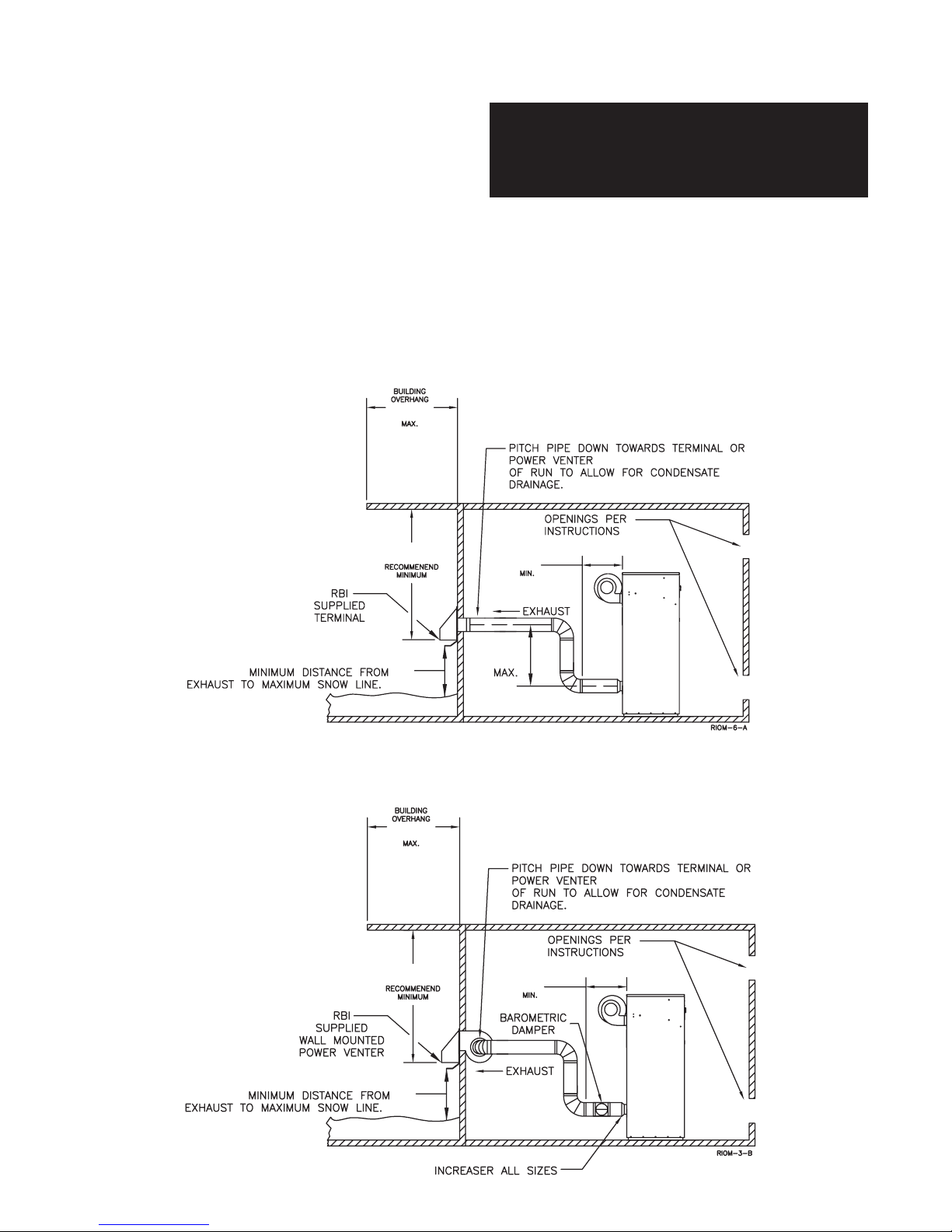
Horizontal Direct Vent Systems – Figures 3 & 4
The vent materials used in horizontal vent systems must
be certified to UL 1738 for installations in the United States,
ULS636 for installations in Canada. The certified vent
terminal from RBI must also be used.
The maximum equivalent length for the horizontal vent
pipe is 60 ft,
are equal to 10 linear ft,
single wall metal vent system passes through an unheated
space, it must be insulated with insulation rated for
400°F,
approved fire-stops. For best results, horizontal vent
systems should be as short and straight as possible.
The vent system must be both gas tight and watertight. All
seams and joints in metal pipes must be joined and sealed
in accordance with the vent system manufacturer’s
instructions.
When horizontal vent runs exceed 5 ft,
supported at 3 ft,
The vent system must be pitched down, toward the vent
terminal, 1/4 in/ft,
vent system passes through an unheated space it must be
insulated with insulation rated for 400˚F,
18.3 m
204°C
must not exceed 60 ft.,
. Each 90˚ elbow and the vent terminal
3.1 m
of pipe. If any part of a
. Structural penetrations must be made using
0.9 m
intervals with overhead hangers.
20 mm/m
. If any part of a single wall metal
1.5 m
they must be
204°C
18.3 m. The
.
Horizontal vent systems shall terminate at least 4 ft,
1.2 m
below, 4 ft,
0.30 m
any building. It must not terminate less than
horizontally from, and in no case above or below, unless
a 4 ft,
meters, gas meters, regulators and relief equipment and
not less than 7 ft,
The bottom of the vent terminal(s) shall be located at
least 5 ft,
there is a minimum 5 ft,
between them. Avoid terminal locations likely to be affected
by winds, snowdrifts, people and pets. Protect building
materials and vegetation from degradation caused by the
flue gases.
Vertical Direct Vent Systems – Figure 5
The maximum equivalent length for the vertical pipe is
60 ft,
equal to 10 linear ft,
wall metal vent system passes through an unheated space,
it must be insulated with insulation rated for 400˚F,
Structural penetrations must be made using approved firestops.
An approved nonrestrictive intake air teminal must be
used. The top of a vertical vent system must extend at least
5
line that it passes through, 4 ft,
terminal, see Figure 5.
In addition the vent system must conform to the dimensions
shown in Figure 5. The penetration point in the roof must
be properly flashed and sealed.
The vent system must be gas tight. All seams and joints
in metal pipes must be joined and sealed in accordance
with the vent system manufacturer’s instructions.
above any door, window or gravity air inlet into
1.2 m
horizontal distance is maintained, from electric
1.5 m
18.3 m
. Each 90˚ elbow and the vent terminal are
1
/2 ft,
1.7 m
above the roof surface and maximum snow
1.2 m
horizontally from or 1 ft,
4 ft, 1.2 m
2.1 m
from any adjacent public walkway.
above the air intake terminal(s) unless
1.5 m
horizontal separation
3.1 m
of pipe. If any part of a single
204°C
1.2 m
above the intake air
.
Combination Direct Vent Systems – Figure 6
The boiler/water heater can be vented vertically with the
intake air piped horizontally through an outside wall. Follow
the instructions in the Intake Air Option – Horizontal
Guidelines on page 5. Also follow the general instructions
in the “COMBUSTION AIR & VENTILATION” and
“GENERAL VENTING GUIDELINES” sections.
6

FUTERA II INSTALLATION AND OPERATION INSTRUCTIONS
Figure 1 - Air Intake Vertical or Thru Wall
Figure 2 - Venting Thru Wall/Vertical
7

FUTERA II INSTALLATION AND OPERATION INSTRUCTIONS
Figure 3 – Horizontal Air Intake and Venting for a Single Direct Vent System
4 FT
1.2 m
1/4 IN. PER FOOT
20 mm/m
3 FT 0.9 m
16 FT 4.9 m
5 FT 1.5 m
1.5 FT 0.5 m
5 FT 1.5 m
When running horizontal combustion air and venting for single or multiple units, exhaust and combustion air terminals
must be installed on the same plane (outside wall) in order to prevent pressure differences due to prevailing winds. In
cold climates, double-wall or insulated inlet pipe recommended to prevent condensation.
Figure 4 – Horizontal Air Intake and Venting for Multiple Direct Vent Systems
8

FUTERA II INSTALLATION AND OPERATION INSTRUCTIONS
Figure 5 - Vertical Air Intake and Venting for Direct Vent System
Figure 6 – Combination Direct Vent Systems
9

FUTERA II INSTALLATION AND OPERATION INSTRUCTIONS
SIDE WALL VENT,
POSITIVE PRESSURE, CATEGORY III
In this configuration the boiler/water heater blower is used
to push the flue products horizontally to the outdoors, see
Figure 7. The air for combustion is taken from the space
in which the unit is installed. The applicable instructions
under the “COMBUSTION AIR & VENTILATION” section
must be followed! The vent guidelines under the Horizontal
Direct Vent Systems section must also be followed.
HORIZONTAL VENT,
NEGATIVE PRESSURE, CATEGORY I
In this configuration a wall-mounted power venter must be
used to pull the flue products horizontally from the unit and
vent them to the outdoors, see Figures 3, 4 & 7A. The air
for combustion is taken from the space in which the unit is
installed, or from the outdoors. The applicable instructions
under the “COMBUSTION AIR & VENTILATION” section
must be followed!
To maximize the performance of single wall sheet metal
vent systems locate 90˚ elbows as far from the boiler as
possible and from one another. For best results, horizontal
vent systems should be as short and straight as possible.
1.5 m
When horizontal vent runs exceed 5 ft,
0.9 m
must be supported at 3 ft,
hangers. The vent system must be pitched down, toward
the vent terminal, 1/4 in/ft,
wall metal vent system passes through an unheated space
it must be insulated with insulation rated for 400˚F,
Horizontal vent systems shall terminate at least 4 ft,
1.2 m
below, 4 ft,
0.30 m
into any building. It must not terminate less than
4 ft,
or below, unless a 4 ft,
is maintained, from electric meters, gas meters, regulators
and relief equipment and not less than 7 ft,
any adjacent public walkway.The bottom of the vent
terminal(s) shall be located at least 5 ft,
air intake terminal(s) unless there is a minimum 5 ft,
1.5 m
locations likely to be affected by winds, snowdrifts, people
and pets. Protect building materials and vegetation from
degradation caused by the flue gases.
To determine the appropriate power venter for the
boiler/water heater, see Table 3. Follow the power venter
manufacturer’s installation instructions.
Table 3 - Power Venter Sizes
above any door, window or gravity air inlet
1.2 m
horizontally from, and in no case above
horizontal separation between them. Avoid terminal
Futera II Power Venter Max. Pipe Length
Model Model FT
500 - 750 HS-3 100
1000-1250 HS-4 100
1500-1950 HS-5 100
1.2 m
intervals with overhead
21 mm/m
horizontally from or 1 ft,
1.2 m
. If any part of a single
horizontal distance
1.5 m
they
204˚C
2.1 m
from
above the
m
31
31
31
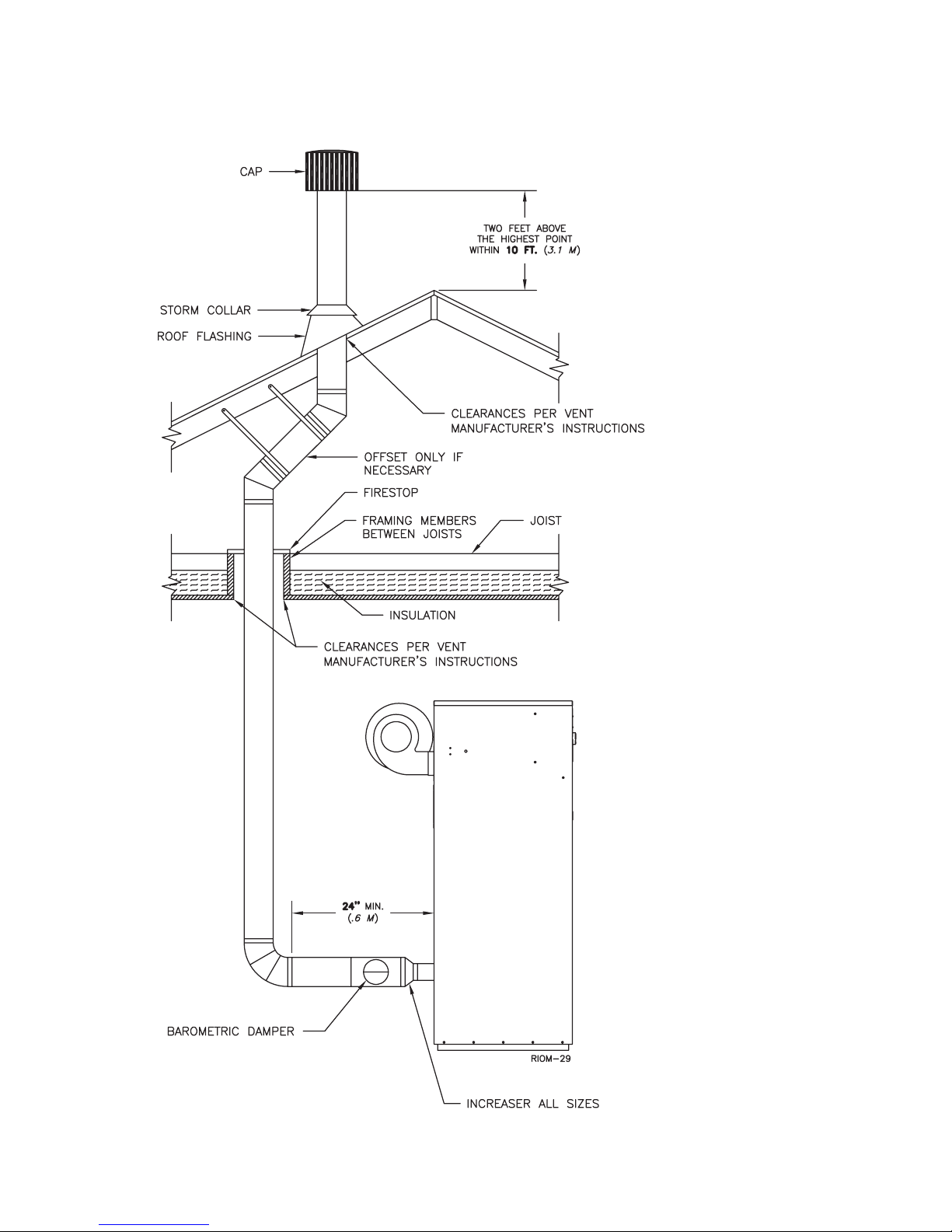
VERTICAL/CHIMNEY VENT,
NEGATIVE PRESSURE, CATEGORY I
The Futera II is listed as a Category I appliance when
vented vertically into a listed metal chimney system or
properly sized masonry chimney, Figures 8 & 9. The
chimney must provide a negative pressure of 0.01 to 0.08
0.25 to 2.0 mm
in,
with the unit running. A barometric damper must be
attached directly to the flue collar increaser as shown.
Multiple Futera II’s can be vented into a single vertical
chimney provided that the breeching and chimney are
properly sized per the latest revision of the National Fuel
Gas Code, ANSI Z223.1.
When more than one appliance is connected to the same
chimney flue, the flue must be large enough to safely vent
the combined output of all of the appliances.
WARNING: If an appliance using any type of a
mechanical draft system operating under positive
pressure is connected to a chimney flue, never
connect any other appliances to this flue. Doing
so can result in excessive levels of carbon
monoxide which can cause severe personal injury
or death!
Chimney Inspection & Sizing
A thorough inspection of the masonry chimney must be
performed to ensure that the chimney is clean, properly
constructed and properly sized. Exterior masonry chimneys
.
should not be used unless properly lined to prevent
condensation and draft problems. Table 3A lists the
equivalent breeching and flue sizes required for the boiler/
water heater.
Table 3A - Equivalent Breeching & Chimney Size,
Model Size Pipe Diameter
750, 1000 10
1250, 1500 12
1750, 1950 14
Note: These sizes are based on a 20 ft,
Vent Connections
Locate the boiler/water heater as close to the chimney as
possible. Use the shortest, straightest vent connector
possible for the installation. If horizontal runs exceed 5 ft,
1.5 m
they must be supported at 3 ft,
overhead hangers. Use a type B, single wall stainless or
single wall galvanized steel vent pipe the same diameter
as the flue collar to connect the boiler/water heater to a
masonry chimney, see Figure 2. When using a listed metal
chimney system use the appropriate vent connector.
W.C. at the boiler/water heater flue collar
Negative Pressure
in
500 8
6.1m
chimney height.
0.9 m
mm
203
254
305
356
intervals with
10
FUTERA II INSTALLATION AND OPERATION INSTRUCTIONS
The vent connector should be sloped up toward the
chimney at a minimum rate of 1/4 in/ft,
21 mm/m
. On
masonry chimneys the connector must terminate flush with
the inside of the chimney flue, Figure 9. Fasten each single
wall vent connection with at least 3 corrosion resistant
sheet metal screws.
Always provide a minimum clearance of 6 in,
152 mm
between single wall vent pipe and any combustible
materials. Type B1 vent may be used, clearance between
it and any combustible material must be as listed.
Figure 7 – Side Wall Venting, Positive Pressure
4 FT
1.2 m
3 FT
0.9 m
WARNING: Failure to maintain minimum
clearances between vent connectors and any
combustible material can result in a fire causing
extensive property damage, severe personal injury
or death!
1/4 IN. PER F00T 20 mm/m
24"
0.6 m
1.5 FT 0.5 m
Figure 7A – Power Venting, Negative Pressure
1.5 FT 0.5 m
4 FT
1.2 m
3 FT
0.9 m
7 FT
2.1 m
24"
0.6 m
1/4 IN. PER F00T 20 mm/m
11
FUTERA II INSTALLATION AND OPERATION INSTRUCTIONS
Figure 8 – Vertical Venting with a Metal Chimney System
12
FUTERA II INSTALLATION AND OPERATION INSTRUCTIONS
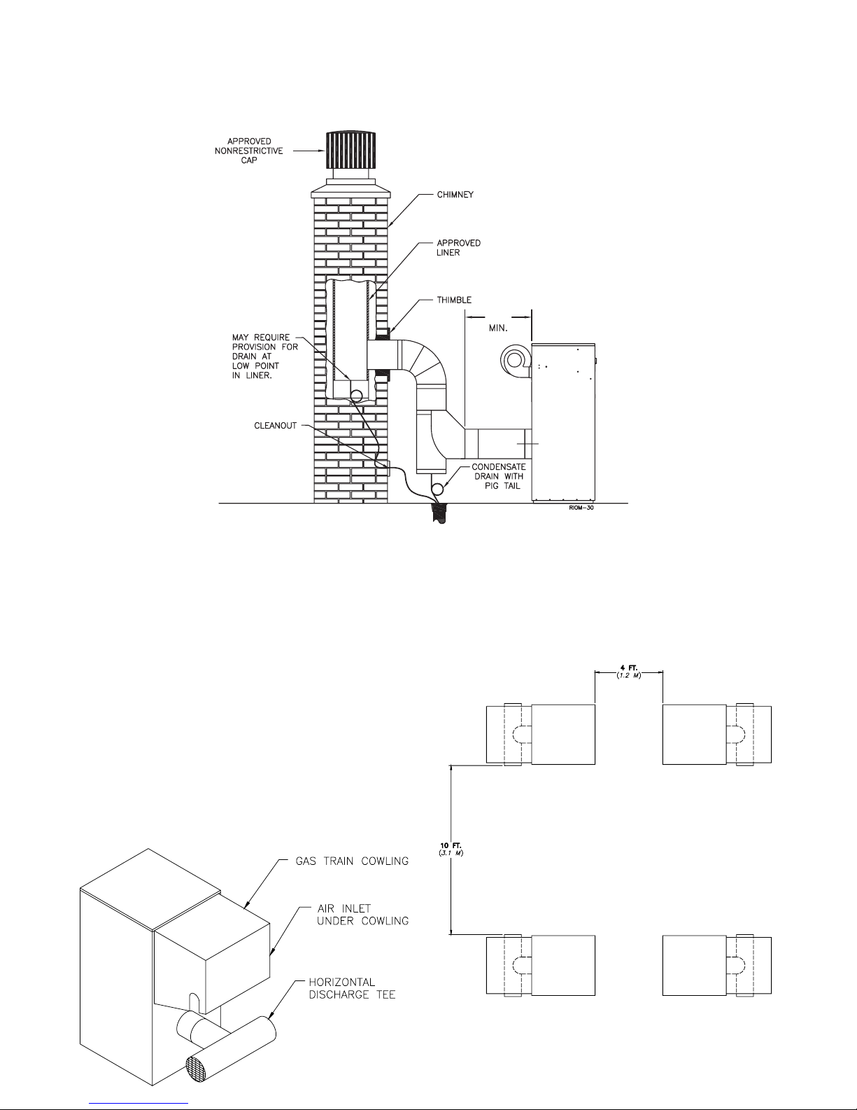
Figure 9 – Vertical Venting using a Masonry Chimney
24"
.6 m
OUTDOOR VENTING
When installed outdoors the Futera II must be fitted with
the factory supplied outdoor hood, air intake adapter with
filter and exhaust terminal, see Figure 10. Multiple units
must be spaced per Figure 11 to prevent flue gases from
being ingested by adjacent units.
3.1 m
0.9 m
from
from
The boiler/water heater must be at least 10 ft,
any door, window or gravity air inlet into any building and
0.9 m
at least 3 ft,
dictate differently.
Avoid locations where wind deflection off of adjacent
walls, buildings or shrubbery might cause a downdraft.
The unit(s) should be located at least 3 ft,
structures. Outdoor installations are not recommended in
areas where the danger of snow blockage exists.
Figure 10 – Outdoor Venting
from any overhang unless local codes
CAUTION: Do not place the boiler/water heater in a
location that would subject it to runoff from adjacent
buildings or damage may occur voiding the warranty!
Figure 11 – Multiple Outdoor Units
13

FUTERA II INSTALLATION AND OPERATION INSTRUCTIONS
COMMON VENT SYSTEMS
If an existing boiler/water heater is removed from a
common venting system, the common venting system may
then be too large for the proper venting of the remaining
appliances connected to it. At the time of removal of an
existing boiler/water heater, the following steps shall be
followed with each appliance remaining connected to the
common venting system placed in operation, while the
other appliances remaining connected to the common
venting system are not in operation.
Au moment du retrait d’une chaudière existante, les
mesures suivantes doivent être prises pour chaque
appareil toujours raccordé au système d’évacuation
commun et qui fonctionne alors que d’autres appareils
toujours raccordés au système d’évacuation ne fonctionnent pas: système d’évacuation
a) Seal any unused openings in the common venting system.
Sceller toutes les ouvertures non utilisées du système d’évacuation.
b) Visually inspect the venting system for proper size and
horizontal pitch and determine there is no blockage or
restriction, leakage, corrosion and other deficiencies
which could cause an unsafe condition.
Inspecter de façon visuelle le système d’évacu-ation
pour déterminer la grosser et l’inclinaison horizontale
qui conviennent et s’assurer que le système est exempt
d’obstruction, d’étranglement de fruite, de corrosion et
autres défaillances qui pourraient présenter des risques.
c) Insofar as is practical, close all building doors and
windows and all doors between the space in which the
appliances remaining connected to the common venting
system are located and other spaces of the building. Turn
on clothes dryers and any appliance not connected to the
common venting system. Turn on any exhaust fans, such
as range hoods and bathroom exhaust, so they will operate
at maximum speed. Do not operate a summer exhaust
fan for a boiler installation. Close fireplace dampers.
Dans la mesure du possible, fermer toutes les portes
et les fenêtres du bâtiment et toutes les portes entre
l’espace où les appareils toujours raccordés du système
d’évacuation sont installés et les autres espaces du
bâtiment. Mettre en marche les sécheuses, tous les
appareils non raccordés au système d’évacuation
commun et tous les ventilateurs d’extraction comme les
hottes de cuisinère et les ventilateurs des salles de bain.
S’assurer que ces ventilateurs fonctionnent à la vitesse
maximale. Ne pas faire fonctionner les ventilateurs
d’été. Fermer les registres des cheminées.
d) Place in operation the appliance being inspected. Follow
the lighting instructions. Adjust thermostat so appliance
will operate continuously.
Mettre l’appareil inspecté en marche. Suivre les
instructions d’allumage. Régler le thermostat de façon
que l’appareil fonctionne de façon continue.
e) Test for spillage at the draft hood relief opening after 5
minutes of main burner operation. Use the flame of a
match or candle, or smoke from a cigarette, cigar or
pipe.
Faire fonctionner le brûleur principal pendant 5 min
ensuite, déterminer si le coupe-tirage déborde à
l’ouverture de décharge. Utiliser la flamme d’une
allunette ou d’une chandelle ou la fumée d’une
cigarette, d’un cigare ou d’une pipe.
f) After it has been determined that each appliance
remaining connected to the common venting system
properly vents when tested as outlined above, return
doors, windows, exhaust fans, fireplace dampers and
any other gas-burning appliance to their previous
condition of use.
Une fois qu’il a été d éterminé, selon la métode
indiquée ci-dessus, que chaque appareil raccordé au
système d’évacuation est mis à l’air libre de façor
adéquate. Remettre les portes et les fenêtres, les
ventilateurs, les registres de cheminées et les appareils
au gaz à leur position originale.
g) Any improper operation of the common venting system
should be corrected so the installation conforms with
the National Fuel Gas Code, ANSI Z223.1/NFPA 54.
When resizing any portion of the common venting
system, the common venting system should be resized
to approach the minimum size as determined using the
appropriate tables in Appendix F in the National Fuel
Gas Code, ANSI Z223.1/ NFPA 54 and or CAN/CGA
B149 Installation Codes.
Tout mauvais fonctionnement du systéme d’évacu-tion
commun devrait étré corrigé de façor que l’installation
soit conforme au National Fue Gas Code, ANSI
Z223.1/NFPA 54 et (ou) aux codes d’installation CAN/
CGA-B149. Si la grosseur d’une section du système
d’ évacuation doit étré modifiée, le système devrait étré
modifié pour respecter les valeurs minimales des
tableaux pertinents de l’appendice F du National Fuel
Gas Code, ANSI Z223.1/ NFPA 54 et (ou) des codes
d’installation CAN/CGA-B149.
GENERAL PIPING REQUIREMENTS
CAUTION: Improper piping of this boiler/water heater
will void the manufacturer’s warranty and can cause
boiler failure resulting in flooding and extensive
property damage! Excessive water hardness causing
scaling in the copper heat exchanger tubes is NOT
covered under the manufacturer’s warranty. Excessive
pitting and erosion of the internal surface of the copper
heat exchanger tubes is NOT covered under the
manufacturer’s warranty if the result of high water flow
rates, see Table 5. Return water temperatures below
52°C
125˚F,
excessive condensation voiding the manufacturer’s
warranty, see Primary /Secondary Piping, Figure 13.
will result in heat exchanger damage from
14
 Loading...