

RBI CB-500, CB-1250, CB-1500, CB-1750, CB-2000 Installation & Operation Manual
...
FTF-IOM-1
FUTERA FUSION SERIES FINNED COPPER
GAS BOILERS (MODEL CB)
& WATER HEATERS (MODEL CW)
INSTALLATION & OPERATION MANUAL
DESIGNED AND TESTED ACCORDING TO A.S.M.E. BOILER AND PRESSURE
VESSEL CODE, SECTION IV FOR A MAXIMUM ALLOWABLE WORKING PRESSURE
OF 160 PSI, 1103 kPa WATER.
WARNING: If the information in this manual is not followed exactly, a fire
or explosion may result causing property damage, personal injury or loss of life.
Do not store or use gasoline or other fl ammable vapors and liquids in the vicinity of
this or any other appliance.
WHAT TO DO IF YOU SMELL GAS:
• Do not try to light any appliance.
• Do not touch any electrical switch. Do not use any phone in your building.
• Immediately call your gas supplier from a neighbor’s phone. Follow the gas
supplier’s instructions.
• If you cannot reach your gas supplier, call the fi re department.
Installation and service must be performed by a qualifi ed installer, service agency or
the gas supplier.
WARNING: Failure to properly vent this unit can cause excessive amounts of carbon
monoxide resulting in severe personal injury or death!
INSTALLER, THESE INSTRUCTIONS TO BE AFFIXED ADJACENT TO THE BOILER / WATER HEATER.
CONSUMER, RETAIN THESE INSTRUCTIONS FOR FUTURE REFERENCE PURPOSES.
260 North Elm Street 7555 Tranmere Drive
Westfi eld, MA 01085 Mississauga, Ontario L5S 1L4 Canada
Phone: (413) 568-9571 Phone: (905) 670-5888
Fax: (413) 568-9613 Fax: (905) 670-5782
www.rbiwaterheaters.com

FUTERA FUSION INSTALLATION AND OPERATION INSTRUCTIONS
AVERTISSMENT. Assurez-vous de bien suivre les instructions données dans cette notice pour
réduire au minimum le risque d’incendie ou d’explosion ou pour éviter tout dommoge matériel,
toute blessure ou la mort
Ne pas entreposer ni utiliser d’essence ou ni d’autres vapeurs ou liquides infl ammables à
proximité de cet appareil ou de tout autre appareil.
QUE FAIRE SI VOUS SENTEZ UNE ODEUR DE GAZ:
• Ne pas tenter d’allumer d’appareil.
• Ne touchez à aucun interrupteur; ne pas vous servir des téléphones se trouvant dans le
bâtiment.
• Appelez immédiatement votre fournisseur de gas depuis un voisin. Suivez les intructions du
fournisseur.
• Si vous ne purvez rejoindre le fournisseur, appelez le service des incendies.
L’installation et l’entretien doivent être assurés par un installateur ou un service d’entretien
qualifi é ou par le fournisseur de gaz.
CONTENTS
Before You Start page 2
Ratings & Capacities page 3
Boiler/Water Heater Location page 3
Combustion Air & Ventilation page 3
General Venting Guidelines page 5
General Piping Requirements page 11
Heating System Piping page 11
Domestic Water Supply Piping page 16
Gas Supply Piping page 20
Electrical Wiring page 21
General Operation page 21
Operating Instructions page 22
Checking & Adjustments page 24
Control Description page 25
MPA Staging Control page 25
Diagnostics page 27
Maintenance page 27
Trouble-Shooting page 29
Repair Parts page 31
Startup Sheet page 38
BEFORE YOU START
This manual covers the application, installation, operation
and maintenance of a Futera Fusion Series fi nned copper
heating boiler/water heater.
To obtain the safe, dependable, effi cient operation and long
life for which this heating boiler/water heater was designed,
these instructions must be read, understood and followed.
The Futera Fusion Series fi nned copper heating boiler/
water heaters have been design certifi ed by CSA for use
with natural and propane gas under the latest revision of
ANSI-Z21.10.3/CSA 4.3, Gas Water Heaters, ANSI-Z21.13/
CSA 4.9, Gas-Fired Low Pressure Steam and Hot Water
Boilers and CAN1-3.1, Industrial and Commercial Gas
Fired Packaged Boilers. Each unit has been constructed
and hydrostatically tested for a maximum working pressure
of 160 psi, 1103 kPa in accordance with Section IV of the
A.S.M.E. Boiler and Pressure Vessel Code.
All aspects of the boiler/water heater installation must
conform to the requirements of the authority having jurisdiction, or, in the absence of such requirements, to the
National Fuel Gas Code, ANSI Z223.1/NFPA 54-latest
revision. Where required by the authority having jurisdiction,
the installation must conform to the Standard for Controls
and Safety Devices for Automatically Fired Boilers, ANSI/
ASME CSD-1.
In Canada, the installation must be in accordance with the
requirements of CSA B149.1 or .2, Installation Code for
Gas Burning Appliances and Equipment.
If installed in the Commonwealth of Massachusetts, you
MUST FOLLOW the additional instructions contained in
RBI’s instruction sheet “MACODE”. If you don’t have a copy
call your RBI representative.
The owner should maintain a record of all service work
performed with the date and a description of the work done.
Include the name of the service organization for future
reference.
Direct all questions to your RBI distributor or contact the
RBI Customer Service Department at: 260 North Elm
Street, Westfi eld, MA 01085 for US or 7555 Tranmere
Drive, Mississauga ONT L5S 1L4 for Canada. Always
include the model and serial numbers from the rating plate
of the boiler/water heater in question.
2

FUTERA FUSION INSTALLATION AND OPERATION INSTRUCTIONS
RATINGS & CAPACITIES
Before undertaking the installation of the Futera
Fusion Series boiler/water heater check the rating
plate to ensure that the unit has been sized properly
for the job. The “Net I=B=R Ratings” specify the
equivalent amount of direct cast iron radiation that
the unit can supply under normal conditions. Also
ensure that the unit has been set up for the type of
gas available at the installation site. Other important
considerations are the availability of an adequate electrical
supply, fresh air for combustion and a suitable chimney or
vent system.
BOILER/WATER HEATER LOCATION
1. This boiler/water heater is suitable for indoor
installations. Locate the boiler/water heater in an area
that provides good access to the unit. Servicing may
require the removal of jacket panels. Allow the
minimum clearances between adjacent construction
and the boiler/water heater as listed in Table 1.
NOTE: Service clearances are not mandatory, but are
recommended to ensure ease of service should it be
required.
Table 1
Clearance to Service
Combustibles Clearance
in mm in mm
Top 6 153 30 762
Back 6 153 24 610
Left Side 6 153 24 610
Right Side 6 153 24 610
Front 6 153 30 762
2. An optimum site will be level, central to the piping
system, close to a chimney or outside wall and have
adequate fresh air for combustion. Ensure that the
boiler/water heater is level from front to back and from
side to side. Use metal shims to level the boiler/water
heater. Electrical and electronic components must also
be protected from exposure to water during operation
and maintenance. DO NOT install this boiler/water
heater in a location that would subject any of the gas
ignition components to direct contact with water or
excessive moisture during operation or servicing.
3. Ensure that the fl oor is structurally sound and will
support the weight of the boiler/water heater.
NOTE: The Futera Fusion may be installed directly on
combustible fl ooring, but never on carpeting.
4. Locate the boiler/water heater in an area that will
prevent water damage to adjacent construction should
a leak occur or during routine maintenance. If such
a location doesn’t exist, a suitable drain pan that’s
adequately drained must be installed under the unit.
5. DO NOT place this boiler/water heater in a location that
would restrict the introduction of combustion air into
the unit or subject it to a negative pressure, see
“GENERAL VENTING GUIDELINES”.
6. NEVER place this boiler/water heater in a location that
would subject it to temperatures at or near freezing,
see the “FREEZE PROTECTION” section on page 11.
WARNING: Never store combustible materials,
gasoline or any product containing flammable
vapors or liquids in the vicinity of the boiler/water
heater. Failure to comply with this warning can
result in an explosion or fire causing extensive
property damage, severe personal injury or death!
COMBUSTION AIR & VENTILATION
WARNING: This boiler/water heater must be
supplied with combustion air in accordance with
Section 5.3, Air for Combustion & Ventilation, of the
latest revision of the National Fuel Gas Code, ANSI
Z223.1/NFPA 54 and all applicable local building
codes. Canadian installations must comply with
CAN/ CGA B149.1 or .2 Installation Code for Gas
Burning Appliances and Equipment, or applicable
provisions of the local building codes. Failure to
provide adequate combustion air for this boiler/
water heater can result in excessive levels of
carbon monoxide which can result in severe
personal injury or death!
To operate properly and safely this boiler/water heater
requires a continuous supply of air for combustion. NEVER
store objects on or around the boiler/water heater!
CAUTION: Combustion air contaminated with
fl uorocarbons or other halogenated compounds such
as cleaning solvents and refrigerants will result in the
formation of acids in the combustion chamber. These
acids will cause premature failure of the boiler/water
heater voiding the warranty!
CAUTION: If the boiler/water heater is operated while
the building is under construction it MUST be
protected from wood, concrete, sheet rock and other
types of dust. Failure to properly protect the unit from
construction dust will damage the unit voiding the
warranty!
Buildings will require the installation of a fresh air duct or
other means of providing make-up air if the intake air option
isn’t used. Any building utilizing other gas burning
appliances, a fi replace, wood stove or any type of exhaust
fan must be checked for adequate combustion air when all
of these devices are in operation at one time. Sizing of an
outside air duct must be done to meet the requirements
of all such devices.
WARNING: Never operate the Futera Fusion in
an environment subjected to a negative pressure
unless it is Direct Vented. Failure to comply with
this warning can result in excessive levels of
carbon monoxide causing severe personal injury
or death!
3

FUTERA FUSION INSTALLATION AND OPERATION INSTRUCTIONS
All Air From Inside The Building
If the Futera Fusion is to be located in a confined
space, the minimum clearances listed in Table 1 must be
maintained between it and any combustible construction.
When installed in a confi ned space without the intake
air option, Figures 5, and 6, two permanent openings
communicating with an additional room(s) are required.
The combined volume of these spaces must have
suffi cient volume to meet the criteria for an unconfi ned
space. The total air requirements of all gas utilization
equipment, fireplaces, wood stoves or any type of
exhaust fan must be considered when making this
determination. Each opening must have a minimum free
area of 1 in
2
/1000 Btu/hr, 2200 mm2/kW based on the
total input rating of ALL gas utilization equipment in the
confined area. Each opening must be no less than
2
100 in
, 64,516 mm2 in size. The upper opening must
be within 12 in, 305 mm of, but not less than 3 in,
76 mm from, the top of the enclosure. The bottom
opening must be within 12 in, 305 mm of, but not less
than 3 in, 76 mm from, the bottom of the enclosure.
All Air From Outside The Building
When installed in a confi ned space without utilizing the
intake air option two permanent openings communicating
directly with, or by ducts to, the outdoors or spaces that
freely communicate with the outdoors must be present. The
upper opening must be within 12 in, 305 mm of, but not
less than 3 in, 76 mm from, the top of the enclosure. The
bottom opening must be within 12 in, 305 mm of, but not
less than 3 in, 76 mm from, the bottom of the enclosure.
Where directly communicating with the outdoors
or communicating with the outdoors through vertical
ducts, each opening shall have a minimum free area of
2
/4000 Btu/hr, 550 mm2/kW of the total input rating
1 in
of all of the equipment in the enclosure.
Where communicating with the outdoors through horizontal
ducts, each opening shall have a minimum free area of
2
/2000 Btu/hr, 1100 mm2/kW of the total input rating
1 in
of all of the equipment in the enclosure.
Table 2 – Make-up Air Louver Sizing
Required Cross Sectional Area
Input 1/4 in 6.4 mm
(MBH) Wire Screen Metal Louvers Wooden Louvers
in
2
cm
75% Free Area 25% Free Area
2
in
2
cm
2
in
2
cm
2
500 125 806 167 1077 500 3226
750 187 1206 250 1613 750 4839
1000 250 1613 333 2148 1000 6452
1250 313 2019 416 2684 1250 8065
1500 375 2419 500 3226 1500 9677
1750 437 2819 583 3761 1750 11,290
1999 500 3226 667 4303 2000 12,900
Canadian installations must comply with CSA B149.1 when
air supply is provided by natural air fl ow from the outdoors
for natural draft, partial fan-assisted, fan-assisted, or
power draft-assisted burners, there shall be a permanent
air supply opening(s) having a cross-sectional area of not
less than 1 in
and including 1 million Btuh, plus 1 in
(155 mm
2
per 7,000 Btuh (310 mm2 per kW) up to
2
per kW) in excess of 1 million Btuh.
2
per 14,000 Btuh
Intake Air Option – General Guidelines
This confi guration provides combustion air directly to the
boiler/water heater’s air intake using a dedicated pipe when
using the direct vent option. The RBI air intake adapter
must be fi tted to the blower inlet. Combustion air can be
drawn in horizontally through the same outside wall which
terminates the exhaust gases or vertically through the roof,
see Figures 1, 2, 3 & 4.
WARNING: Common intake air systems may be
used provided the common duct is sized properly
and an intake combustion air damper is installed
in the intake air pipe of each heater. Improper
installation can result in excessive levels of carbon
monoxide which can cause severe personal injury
or death!
Single wall galvanized smoke pipe, single wall aluminum
pipe, fl exible aluminum pipe, PVC or CPVC pipe can be
used for the intake air pipe. It must be sized per Table 3.
When ducts are used, they must have the same crosssectional area as the free area of the opening to which they
connect.
When calculating the free area necessary to meet the
make-up air requirements of the enclosure, consideration
must be given to the blockage effects of louvers, grills and
screens. Screens must have a minimum mesh size of
1/4 in, 6.4 mm. If the free area through a louver or grill is
not known, ducts should be sized per Table 2.
Table 3 - Intake Air Pipe Sizing
Model For Vertical For Horizontal
Size (Up To 60')
in mm in mm
500 8 203 6 152
750 8 203 6 152
1000 8 203 6 152
1250 10 254 8 203
1500 10 254 10 254
1750 12 305 12 305
2000 12 305 12 305
All joints in metal intake air systems must be secured using
corrosion resistant fasteners and sealed using a suitable
Silicone caulk. If PVC or CPVC is used, the joints must be
cleaned with a suitable solvent and connected using a
solvent based PVC cement. The combustion air system
MUST be supported by the building structure not the
boiler/water heater.
4
FUTERA FUSION INSTALLATION AND OPERATION INSTRUCTIONS
CAUTION: A combustion air damper interlocked with
the unit should be installed in the intake air pipe when
the infi ltration of subfreezing air could occur, otherwise
the unit could freeze up voiding the warranty!
Intake Air Option – Vertical Guidelines
The maximum equivalent length for the vertical intake
air pipe is 60 ft, 18.3 m. Each 90˚ elbow and the intake
air terminal are equal to 10 linear ft, 3.0 m of pipe, see
Table 3.
An approved, nonrestrictive intake air terminal must be
used. The intake air terminal must terminate as shown in
Figure 3. The penetration point in the roof must be properly
fl ashed and sealed.
Intake Air Option – Horizontal Guidelines
The maximum equivalent length for the horizontal intake
air pipe is 60 ft, 18.3 m. Each 90˚ elbow and the intake air
terminal are equal to 10 linear ft, 3.0 m of pipe. If horizontal
runs exceed 5 ft 1.5 m they must be supported at 3 ft,
0.9 m intervals with overhead hangers. The certifi ed intake
air terminal from RBI must be used, see Figures 1, 2
and 4.
GENERAL VENTING GUIDELINES
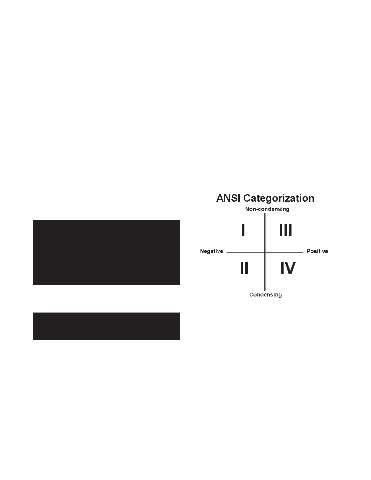
VENT SYSTEM OPTIONS
The Futera Fusion may be vented the following ways:
1) Direct Vent, Positive Pressure, Category IV uses a
vent system certifi ed to UL 1738 for installations in the
United States, ULC S636 for installations in Canada.
Combustion air is piped from the outdoors to the
blower inlet.
2) Side Wall Vent, Positive Pressure, Category IV uses
a vent system certifi ed to UL 1738 for installations
in the United States, ULC S636 for installations in
Canada. Combustion air is obtained from the space in
which the unit is installed.
3) Must consult factory when venting single or multiple
unit(s) over 60 equivalent feet. Mechanical system may
be required.
NOTE: All venting, combustion air material supplied by
installer.
WARNING: The vent installation must be in
accordance with Part 7, Venting of Equipment, of
the National Fuel Gas Code, ANSI Z223.1/NFPA 54latest revision or applicable provisions of the local
building codes. Canadian installations must
comply with CAN/CGA B149.1 or .2 Installation
Code. Improper venting can result in excessive
levels of carbon monoxide which can result in
severe personal injury or death!
All vent systems must be fully supported by the building
structure and not by the boiler/water heater. Appropriate
thimbles and fi re-stops must be used where required.
WARNING: Common vent systems must be
properly engineered and sized, please contact the
factory.
5

FUTERA FUSION INSTALLATION AND OPERATION INSTRUCTIONS
DIRECT VENT,
POSITIVE PRESSURE, CATEGORY IV
In this confi guration the boiler/water heater blower is used
to push the fl ue products to the outdoors while drawing
combustion air from the outdoors. The Intake Air
Option instructions under the “COMBUSTION AIR &
VENTILATION” section must be followed! The vent system
must be sized per Table 4.
Table 4 – Category IV
Model Pipe Diameter (Min.)
Size (Up to 60')
in mm
500 7 178
750 7 178
1000 7 178
1250 8 203
1500 8 203
1750 10 254
2000 10 254
Horizontal Direct Vent Systems – Figures 1 & 2
The vent materials used in horizontal vent systems must
be certifi ed to UL 1738 for installations in the United States,
ULC S636 for installations in Canada. The certifi ed vent
terminal from RBI must also be used.
The maximum equivalent length for the horizontal vent pipe
is 60 ft, 18.3 m. Each 90˚ elbow and the vent terminal are
equal to 10 linear ft, 3.0 m of pipe. If any part of a single
wall metal vent system passes through an unheated space,
it must be insulated with insulation rated for 400° F, 204°C.
Structrual penetrations must be made using approved fi restops. For best results, horizontal vent systems should be
as short and straight as possible.
Horizontal vent systems shall terminate at least 4 ft,
1.2 m below, 4 ft, 1.2 m horizontally from or 1 ft,
0.30 m above any door, window or gravity air inlet into
any building. It must not terminate less than 4 ft, 1.2 m
horizontally from, and in no case above or below, unless
a 4 ft, 1.2 m horizontal distance is maintained, from electric
meters, gas meters, regulators and relief equipment and
not less than 7 ft, 2.1 m from any adjacent public walkway.
The bottom of the vent terminal(s) shall be located at
least 5 ft, 1.5 m above the air intake terminal(s) unless
there is a minimum 5 ft, 1.5 m horizontal separation
between them. Avoid terminal locations likely to be affected
by winds, snowdrifts, people and pets. Protect building
materials and vegetation from degradation caused by the
fl ue gases.
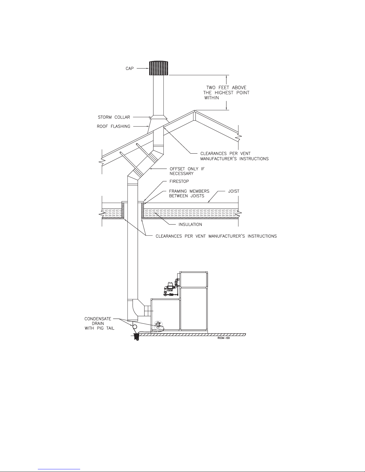
Vertical Direct Vent Systems – Figure 3
If any part of a single wall metal vent system passes
through an unheated space, it must be insulated with
insulation rated for 400˚F, 204°C. Structural penetrations
must be made using approved fi re-stops.
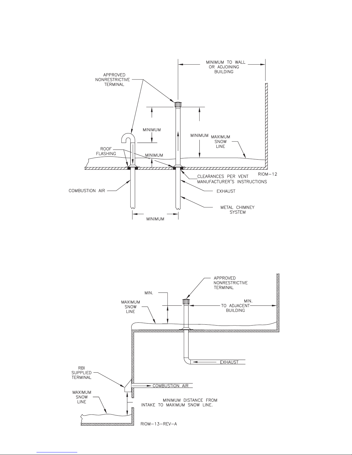
An approved, nonrestrictive vent terminal must be used.
The top of a vertical vent system must extend at least
1
/2 ft, 1.7 m above the roof surface and maximum snow
5
line that it passes through, 4 ft, 1.2 m above the intake air
terminal, see Figure 3.
In addition the vent system must conform to the dimensions
shown in Figure 3. The penetration point in the roof must
be properly fl ashed and sealed.
The vent system must be gas tight. All seams and joints
in metal pipes must be joined and sealed in accordance
with the vent system manufacturer’s instructions.
The vent system must be both gas tight and watertight.
All seams and joints in metal pipes must be joined and
sealed in accordance with the vent system manufacturer’s
instructions.
When horizontal vent runs exceed 5 ft, 1.5 m they must be
supported at 3 ft, 0.9 m intervals with overhead hangers.
The vent system must be pitched back, towards the secondary
heat exchanger, 1/4 in/ft, 20 mm/m. If any part of a single wall
metal vent system passes through an unheated space
it must be insulated with insulation rated for 400˚F, 204°C.
Combination Direct Vent Systems – Figure 4
The boiler/water heater can be vented vertically with the
intake air piped horizontally through an outside wall. Follow
the instructions in the Intake Air Option – Horizontal
Guidelines. Also follow the general instructions in the
“COMBUSTION AIR & VENTILATION” and “GENERAL
VENTING GUIDELINES” sections.
6
FUTERA FUSION INSTALLATION AND OPERATION INSTRUCTIONS
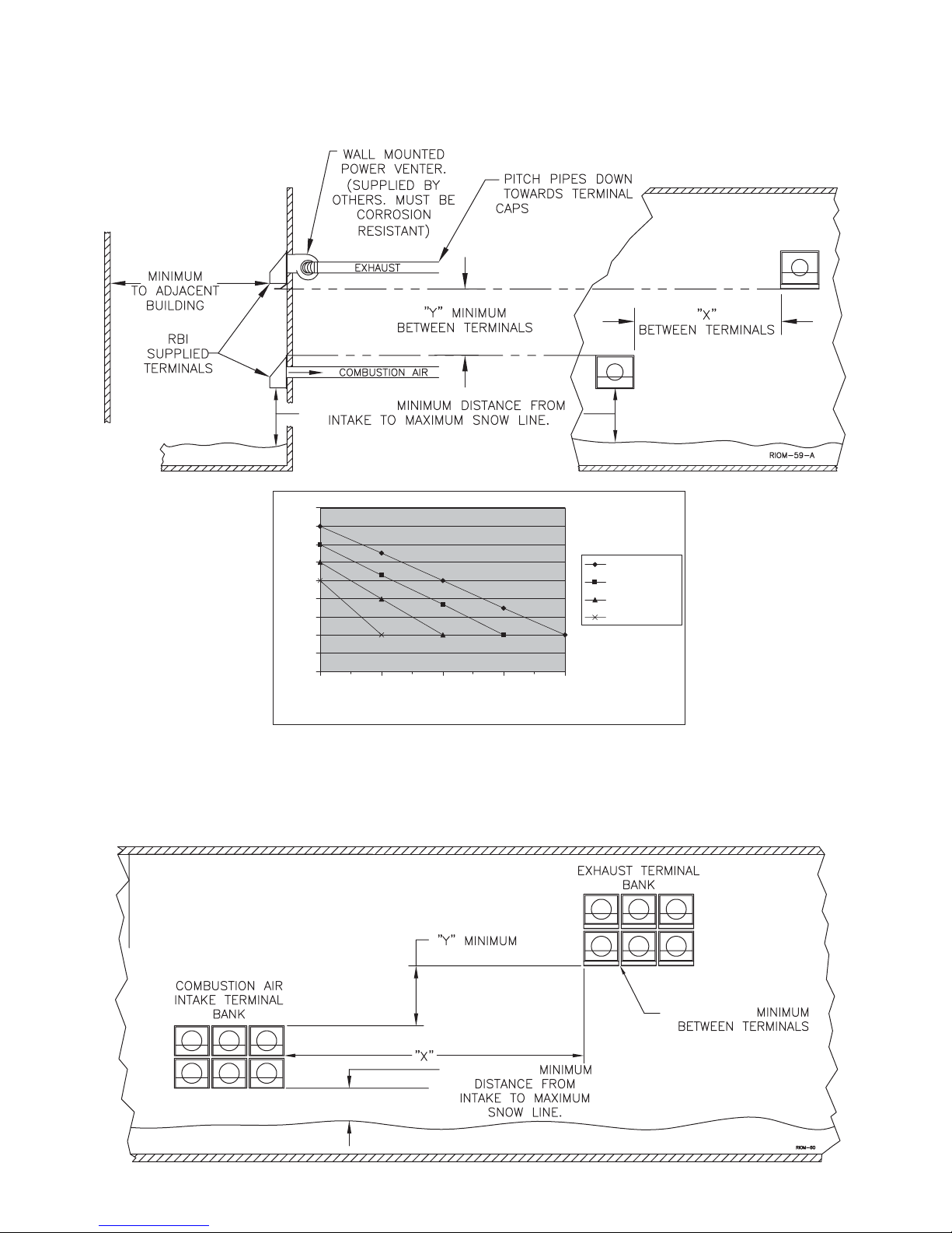
Figure 1– Horizontal Combustion Air and Venting for a Single Unit
16 FT 4.9 m
1.5 FT 0.5 m
9
8
Y
7
,
e
c
6
n
at
5
si
D
4
la
ci
3
t
re
2
V
1
0
0 5 10 15 20
Horizontal Distance, X
1/4 IN. PER FOOT
20 mm/m
2000 & Larger
1201 To 2000
901 To 1200
200 To 900
1000 BTU'S
When running horizontal combustion air and venting for single or multiple units, exhaust and combustion air terminals
must be installed on the same plane (outside wall) in order to prevent pressure differences due to prevailing winds. In
cold climates, double-wall or insulated inlet pipe recommended to prevent condensation.
Figure 2 – Horizontal Combustion Air and Venting for Multiple Units
2 IN. 5.0 cm
1.5 FT 0.5 m
7
FUTERA FUSION INSTALLATION AND OPERATION INSTRUCTIONS
Figure 3 - Vertical Air Intake and Venting for Direct Vent System
10 FT 3.1 m
4 FT
1.2 m
1.5 FT
0.5 m
5 1/2 FT
1.7 m
Figure 4 – Combination Direct Vent Systems
3 FT. 1 m
5 FT
1.5 m
10 FT. 3.1 m
1.5 FT. .5 m
8

FUTERA FUSION INSTALLATION AND OPERATION INSTRUCTIONS
SIDE WALL VENT,
POSITIVE PRESSURE, CATEGORY IV
In this confi guration the boiler/water heater blower is used
to push the fl ue products horizontally to the outdoors, see
Figure 5. The air for combustion is taken from the space
in which the unit is installed. The applicable instructions
under the “COMBUSTION AIR & VENTILATION” section
must be followed! The vent guidelines under the Horizontal
Direct Vent Systems section must also be followed.
Figure 5 – Side Wall Venting
20 mm/m
1/4 IN. PER F00T
1.5 FT 0.5 m
9
FUTERA FUSION INSTALLATION AND OPERATION INSTRUCTIONS
Figure 6 – Vertical Venting with a Metal Chimney System
10 FT. 3.1 m
10

FUTERA FUSION INSTALLATION AND OPERATION INSTRUCTIONS
GENERAL PIPING REQUIREMENTS
CAUTION: Improper piping of this boiler/water heater
will void the manufacturer’s warranty and can cause
boiler failure resulting in flooding and extensive
property damage! Excessive water hardness causing
scaling in the copper heat exchanger tubes is NOT
covered under the manufacturer’s warranty, see Table
7. Excessive pitting and erosion of the internal surface
of the copper heat exchanger tubes is NOT covered
under the manufacturer’s warranty if the result of high
water fl ow rates, see Table 7.
NOTE: Shut off valves and unions should be installed
at the inlet and outlet connections of the boiler/hot
water heater to provide for isolation of the unit should
servicing be necessary.
Freeze Protection
Installations in areas where the danger of freezing exists
are not recommended unless proper freeze protection is
provided. The following precautions MUST be observed:
1. A continuous fl ow of water through the unit MUST be
maintained! The pump responsible for fl ow through the
boiler/water heater must run continuously!
2. An ethylene glycol/water mixture suitable for the
minimum temperature that the unit will be exposed to
must be used. The pump must be capable of producing
a minimum of 15% more fl ow and overcoming a 20%
increase in head loss. Domestic water systems must be
isolated from the water heater by the use of a heat
exchanger or other approved method.
3. If the unit must be shut off for any reason the electric,
gas and water supplies MUST be shut off and the unit
and its pump completely drained.
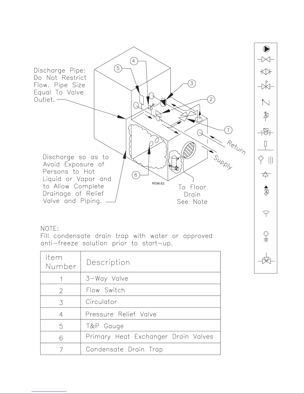
Condensate Piping
The condensate trap provided with the boiler must be
attached to the bottom pan and piped to a suitable fl oor
drain or condensate pump. If a condensate neutralization
device is installed, it must be positioned prior to boiler room
drain. Condensate fi ll trap must be maintained with fl uid.
Relief Valve
Pipe the discharge of the pressure relief valve as shown
in Figure 8.
WARNING: Never install any type of valve between
the boiler/water heater and the relief valve or an
explosion causing extensive property damage,
severe personal injury or death may occur!
Flow Switch
The fl ow switch supplied with the boiler/water heater must
be wired to the terminal strip in the control panel to prevent
the boiler from fi ring unless there’s adequate water fl ow
through the unit. The fl ow switch must be installed in the
supply piping adjacent to the boiler outlet connection.
CAUTION: Failure to properly install the fl ow switch
may result in damage to the boiler/water heater heat
exchanger voiding the warranty!
HEATING SYSTEM PIPING
General Piping Requirements
All heating system piping must be installed by a qualifi ed
technician in accordance with the latest revision of the
ANSI/ASME Boiler and Pressure Vessel Code, Section IV,
and ANSI/ASME CSD-1, Standard for Controls and Safety
Devices for Automatically Fired Boilers. All applicable local
codes and ordinances must also be followed. A minimum
clearance of 1 in, 25 mm must be maintained between
heating system pipes and all combustible construction. All
heating system piping must be supported by suitable
hangers not the boiler. The thermal expansion of the
system must be considered when supporting the system.
A minimum system pressure of 12 psig, 82.7 kPa must
be maintained.
Heating Boiler Piping Connections
The supply and return connections should be sized to suit
the system, see Table 6.
Table 6 – Supply & Return Pipe Sizing
Model Size Supply Size Return Size
500 thru 1000 2" NPT 2" NPT
1250 thru 2000 2 1/2" NPT 2 1/2" NPT
Pump Requirements
This low mass boiler requires a continuous minimum water
fl ow for proper operation. The system pump must be sized
to overcome the head loss of the boiler and the heating
system in order to achieve the required temperature rise.
Table 7 provides the heat exchanger pressure drop and
temperature rise fi gures. The temperature rise across the
boiler must never exceed 35˚F, 19.4˚C. The adjustable
pump delay turns the pump on each time the burner fi res
and runs the pump for 20 to 600 seconds after the call for
heat is satisfi ed.
11
FUTERA FUSION INSTALLATION AND OPERATION INSTRUCTIONS
Figure 8 – Futera Fusion Piping
Pump
Valve
Balance Valve
Pressure
Reducing Valve
Check Valve
Pressure
Relief Valve
Flow Switch
Thermometer
Aquastat Union
Automatic
Air Vent
Temperature &
Pressure
Relief Valve
Vacuum
Relief Valve
Drain Valve
(Typ.)
3-Way
Mixing Valve
12
 Loading...