

Page 1
'$37$*0.
82-0403
Gas'JSFE %JSFDU 7FOU
4UBJOMFTT 4UFFM #PJMFST
$,4FSJFTo$,$,
$POUSPM Manual
$POUSPM"EKVTUNFOUBOE
0QFSBUJPO Instructions
5IJTJOTUSVDUJPONBOVBMBQQMJFTPOMZUP
3#*GJSNXBSFWFSTJPOY POWFSTJPOY
DPOUSPMCPBSET
Also read and follow:
'MFY$PSF$,4FSJFT(BT#PJMFS
*OTUBMMBUJPOBOE0QFSBUJOH
*OTUSVDUJPO.BOVBM
is manual is intended only for use by a qualied heating installer/technician. Read and follow this manual, all supplements
and related instructional information provided with the boiler. Install, start and service the boiler only in the sequence and
methods given in these instructions. Failure to do so can result in severe personal injury, death or substantial property damage.
Do not use the boiler during construction. Construction dust and particulate, particularly drywall dust, will cause contamination
of the burner, resulting in possible severe personal injury, death or substantial property damage. e boiler can only be operated with
a dust-free air supply. Follow the instruction manual procedures to duct air to the boiler air intake. If the boiler has been contaminated
by operation with contaminated air, follow the instr uction manual guidelines to clean, repair or replace the boi ler if necessary.
Ax these instructions near to the boiler. Instruct the building owner to retain the instructions for future use by a qualied
service technician, and to follow all guidelines in the User’s Information Manual.
)
Copyright 201 Mestek, Inc.
Page 2

Information contained in this publication regarding device applications and
the like is provided only for your convenience and may be superseded by
updates. It is your responsibility to ensure that your application meets with
your specifications.
RBI MAKES NO REPRESENTATIONS OR WARRANTIES OF ANY KIND
WHETHER EXPRESS OR IMPLIED, WRITTEN OR ORAL, STATUTORY
OR OTHERWISE, RELATED TO THE INFORMATION, INCLUDING BUT
NOT LIMITED TO ITS CONDITION, QUALITY, PERFORMANCE,
MERCHANTABILITY OR FITNESS FOR PURPOSE.
http://www.rbiwaterheaters.com/
The RBI name and logo, Mestek name and logo, FlexCore CK -
Series, HeatNet, and H-Net name and logo are registered
trademarks of Mestek, Incorporated in the U.S.A. and other
countries.
BACnet is a registered trademark of ASHRAE. LonWorks is a
registered trademark of Echelon Corporation. All trademarks
mentioned herein are property of their respective companies.
© 2012, Mestek Technology Incorporated, Printed in the U.S.A., All
Rights Reserved.
Page 3

TABLE OF CONTENTS HeatNet Control V3
TABLE OF CONTENTS
TABLE OF CONTENTS ......................................................................................................................... 3
Introduction .......................................................................................................................................... 6
THE FLEXCORE CK -SERIES V3 HEATNET CONTROL .........................................................................................................................6
Features & Specifications ................................................................................................................... 8
STANDARD FEATURES OVERVIEW .....................................................................................................................................................8
Specifications ..................................................................................................................................... 10
Components & Accessories .............................................................................................................. 11
PART NUMBER .............................................................................................................................................................................. 11
SETUP & OPERATION ....................................................................................................................... 12
BASIC MULTI BOILER SYSTEM OPERATION ....................................................................................................................................... 12
MIXED BOILER TYPES USING PRIORITY SETS ................................................................................................................................... 13
MIXED BOILER SYSTEM OPERATION ................................................................................................................................................ 14
START/STOP PRIORITY CONDITIONS ............................................................................................................................................... 16
SELECTING MIXED BOILERS ........................................................................................................................................................... 17
MIXED SYSTEM TYPE 1: HIGH SYSTEM TURNDOWN ......................................................................................................................... 17
MIXED SYSTEM TYPE 2: CONDENSING/NON-CONDENSING ................................................................................................................. 20
Heating Control Methods ................................................................................................................... 24
HEATING METHOD 1 ...................................................................................................................................................................... 24
HEATING METHOD 2 ...................................................................................................................................................................... 24
HEATING METHOD 3 ...................................................................................................................................................................... 24
HEATING METHOD 4 ...................................................................................................................................................................... 24
HEATING METHOD 5 ...................................................................................................................................................................... 24
OPERATING LIMIT .......................................................................................................................................................................... 24
INPUT PRIORITIES .......................................................................................................................................................................... 25
HEATING METHOD 1 HEAT DEMAND ................................................................................................................................ ............ 25
HEATING METHOD 2 STAGE CONTROL T1-T2 ................................................................................................................................ 26
HEATING METHOD 3 4-20 MA CONTROL .......................................................................................................................................... 26
HEATING METHOD 4 AA INPUT........................................................................................................................................................ 27
HEATING METHOD 5 MODBUS COMMUNICATIONS ........................................................................................................................... 27
Domestic Hot Water Methods ............................................................................................................ 28
DHW METHOD 1: DHW HEATING ONLY USING A DHW MASTER AND MEMBER BOILER(S) EMPLOYING H-NET .................................... 29
DHW METHOD 2: FAILSAFE COMBINATION DHW AND SPACE HEATING WITH A MASTER BOILER AND MEMBER BOILERS UTILIZING
VALVES (MASTER TYPE: COMBINATION) ......................................................................................................................................... 33
DHW METHOD 2: FAILSAFE COMBINATION DHW AND SPACE HEATING WITH A MASTER BOILER AND MEMBER BOILERS UTILIZING PUMPS
(MASTER TYPE: COMBINATION) ..................................................................................................................................................... 35
DHW METHOD 3: DHW HEATING ONLY, USING A HEADER SENSOR INPUT .......................................................................................... 40
DHW METHOD 4A: SPACE HEATING WITH DHW OVERRIDE OF SETPOINT ON MASTER, USING AN AQUASTAT ......................................... 43
DHW METHOD 4B: SPACE HEATING WITH DHW OVERRIDE OF SETPOINT ON MASTER, USING A DHW 10K TANK SENSOR ..................... 46
DHW METHOD 5A: LOCAL DHW TANK HEATING USING A 10K TANK SENSOR. ..................................................................................... 49
DHW METHOD 5B: LOCAL DHW TANK HEATING USING A THERMOSTAT & HYBRID SENSOR. ................................................................ 53
DHW METHOD 6: DHW USING DIRECT CONTROL ......................................................................................................................... 55
Page 3
Page 4

DHW MAXIMUM RUNTIME .............................................................................................................................................................. 55
BASE LOADING, RELAY CONTROL ................................................................................................................................................... 56
Using the 4-20 mA input (OPTIONAL) ............................................................................................... 59
SETPOINT PRIORITIES ................................................................................................ .................................................................... 60
Circulator Pump Options ................................................................................................................... 60
Local Pump Options ........................................................................................................................... 62
Combustion Air Damper .................................................................................................................... 63
Outdoor Reset..................................................................................................................................... 63
Sensors ............................................................................................................................................... 64
Stack Temperature ............................................................................................................................. 64
Security ............................................................................................................................................... 64
Save/Restore Configuration Settings ................................................................................................ 64
USB Features ...................................................................................................................................... 64
Diagnostics ......................................................................................................................................... 65
Blower Protection ............................................................................................................................... 65
Communications ................................................................................................................................ 66
Failsafe Modes ................................................................................................................................ .... 66
FAILSAFE REQUIREMENTS: .................................................................................................................................................... 66
Limited Flow Boiler Control Options ................................................................................................. 67
FlexCore Multi Heat Exchangers ....................................................................................................... 69
(3) HEAT EXCHANGER WIRING ........................................................................................................................................................ 71
HeatNet Online ................................................................................................................................ .... 72
Wiring Connections ............................................................................................................................ 73
Home Screen Navigation ................................................................................................................... 85
Home Screen ...................................................................................................................................... 86
Home Screen Messages ..................................................................................................................... 87
HEATING MODE MESSAGES: ........................................................................................................................................................... 87
SETPOINT SOURCE MESSAGES ....................................................................................................................................................... 88
GENERAL MESSAGES: ................................................................................................................................................................... 88
Calibration ........................................................................................................................................... 95
CALIBRATION WITH MULTIPLE HEAT EXCHANGERS ............................................................................................................................ 96
Log Entry ............................................................................................................................................. 97
CONTROL SETTINGS MENU .............................................................................................................. 98
CONTROL SETTINGS MENU— PAGE 1 ............................................................................................ 99
CONTROL SETTINGS MENU— PAGE 2 .......................................................................................... 107
CONTROL SETTINGS MENU — PAGE 3 ......................................................................................... 115
Page 4
Page 5

TABLE OF CONTENTS HeatNet Control V3
CONTROL SETTINGS MENU — PAGE 4 ......................................................................................... 117
MODBUS Communications ............................................................................................................. 118
Worksheet ......................................................................................................................................... 129
Type II Thermistor Resistance/Temperature Table ........................................................................ 134
Page 5
Page 6
FEATURES & SPECIFICATIONS HeatNet Control V3
SETPOINT
UPPER HEAT
BAND LIMIT
LOWER HEAT
BAND LIMIT
Boilers Staged
ON
BOILERS
STAGED
OFF
Time
WATER
TEMPERATURE
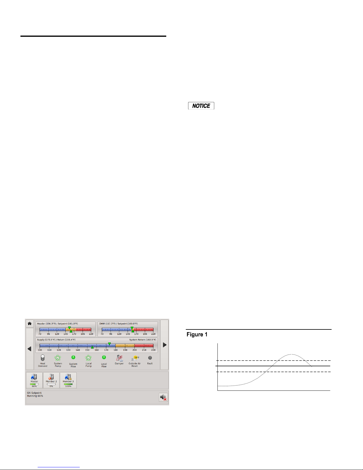
target setpoint. This function is displayed in the Home
Introduction
Screen. While performing this task, the control also
monitors dedicated external limits in a limit string and
provides an orderly shutdown and fault indication in the
The FlexCore CK-Series V3 HeatNet
Control
The FlexCore CK -Series boiler control is designed to
provide the FlexCore CK -Series of boilers with an
integrated boiler management system on every boiler.
Designed for the Air-Fuel coupled FlexCore CK -Series
boilers, the FlexCore CK -Series HeatNet control provides
for optimized heating efficiency without the need for a “wall
mount control”. Since the FlexCore CK -Series modular
control method is based on digital communications, analog
control signals are not required. Although the use of analog
control signals is still supported (4-20 mA control loops and
0-10vdc control voltages), a higher level of control
precision, repeatability, and feedback is gained with digital
communications control.
With the FlexCore CK -Series, optimized heating efficiency
is accomplished by setting the Modulation Maximum (ModMax) setting to exploit the inverse efficiency curve. This
value can be adjusted so that as each boiler is added, it
operates at its maximum turndown. This allows the
maximum number of boilers to operate at their lowest
inputs, until all boilers are firing. Once all boilers are firing,
full range modulation control is allowed. An outdoor reset
function is also provided to assist in the optimized heating
event of a tripped limit. The monitored limits include a
HIGH LIMIT AQUASTAT, LOW WATER CUTOFF,
GAS PRESSURE, FLOW, IGNITION CONTROL fault,
GAS VALVE alarm, VARIABLE FREQUENCY DRIVE
alarm, and other optional or user selectable limits.
The HIGH LIMIT circuit is independent of
the control and shuts down the ignition
control and the boiler if the control board or
other component of the boiler was to
malfunction. The control will continue to
function and report the fault, but its ability to
control the boiler will end.
Each FlexCore CK-Series boiler employing this control can
function as either a Master or a member. This allows one
boiler (Master) to be in control of target temperature. The
other boilers (Members) only respond to the commands
issued by the Master. If using an external control, all boilers
can be setup as members. The following will define the
roles of Master and member.
Master
A boiler becomes a Master when a temperature sensor is
connected to the J10 “SYSTEM HEADER” terminals. The
sensor is auto-detected.
efficiency of the FlexCore CK -Series boilers.
The Master senses and controls the common system
The FlexCore CK -Series boiler with the FlexCore CK Series H-Net control, can be operated in multiple ways:
1. As a stand-alone boiler.
2. A boiler in a Boiler Network using the HeatNet®
header/loop water temperature using a system setpoint. It
uses any boilers it finds (over the H-Net communications
cable) to accomplish this. It can also monitor the Outside
Air (OA) temperature to provide outdoor reset functionality.
Only one Master is allowed in a system.
(H-Net®) protocol.
3. A member boiler to a boiler management system with
multiple input control methods.
When operating as a Master, the boiler provides a control
method using a PID algorithm to regulate water
temperature. This algorithm allows for a single boiler
(Master), or multiple (Master + Member) boilers.
Home Screen
The primary purpose of the control is to maintain the boiler
water temperature at the supply or the header sensor using a
Page 6
Heat band
The control algorithm is based upon a Heat Band, at the
center of which is the setpoint. While below the Heat Band,
boilers are staged on and modulated up until the Heat Band
is entered. Once in the Heat Band, modulation is used to
Page 7
Features and Specifications HeatNet Control V3
maintain setpoint. Boilers are shut down only when the top
of the Heat Band is breached. Timers are also used to
prevent short cycling.
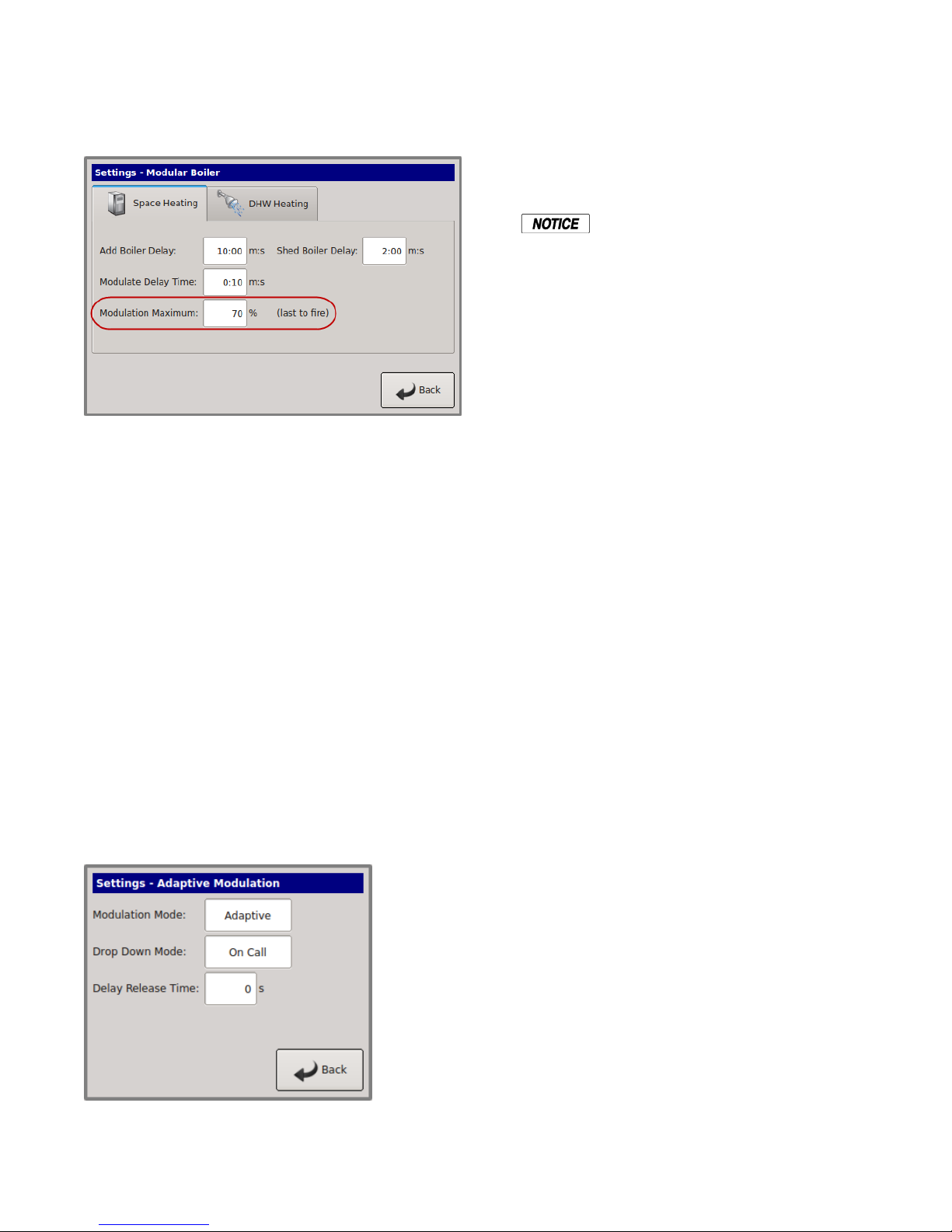
While staging the boilers on, a modulation clamp is used to
hold the boilers at a lower fire rate until the last boiler is
fired. Once the last boiler fires the modulation clamp is
removed, and all boilers are allowed to fire above this
clamped percentage up to 100%. This “boiler efficiency”
clamp is defaulted to 70% and thus limits all of the boilers
individual outputs to 70% until the last boiler fires. All
running boilers modulate up and down together, always at
the same modulation rate. As a general rule, this percentage
should be no lower than twice the minimum turndown to
minimize short cycling.
ADAPTIVE MOD: DROP DOWN. Once the Main Valve
(on the newly added boiler) is opened, and the DELAY
RELEASE timer equals zero, the PID algorithm is allowed
to control the system modulation. Setting the DELAY
RELEASE timer will allow some “soak” time of the newly
added boiler before releasing modulation control to the PID.
The ADAPTIVE MOD menus are disabled
on a Member boiler, but are still visible.
Member
If a “SYS/DHW HEADER” sensor is not connected to J10,
a boiler always defaults to the role of Member.
The Member boiler can operate as part of a multi-boiler
system or as a stand-alone unit.
In a multi-boiler system the Member typically receives its
command signals from a designated Master-boiler. It is also
capable of receiving inputs from an external control system.
The boiler responds to these signals, to start/stop the burner,
and/or to modulate the firing rate. The outlet water
temperature is also monitored. If the outlet temperature
approaches the operating limit temperature setpoint
(adjustable), the boilers firing rate is limited and its
modulation value is reduced to minimize short-cycling. If
the operating limit is exceeded, or if an interlock trips, the
boiler is shut down. When connected with a network cable,
in a Master/Member role, the Members' status is
interrogated by the Master boiler.
When additional boilers are needed to achieve setpoint in
the system, the Master boiler employs an ADAPTIVE
MODULATION algorithm to prevent over firing of the
system. The Master communicates over the H-Net to view
the exact status of each Member boiler. When a new boiler
is added, the Master boiler adjusts the system modulation
rate lower to compensate for the BTUs that will be
introduced by the newly added boiler. This adjustment
occurs when the newly added Member boiler enters its ON
CALL state (default setting). This can be changed to PILOT
when the new boiler is called using the menu:
In a stand-alone installation the Member typically receives
its command signals internally and operates based upon the
outlet water temperature input and the established settings in
the menu (Local Set-point) to start/stop the burner, and/or to
modulate the firing rate. If the operating limit is exceeded,
or if an interlock trips, the boiler is shut down. As in a
multi-boiler system, a stand-alone Member boiler is also
capable of receiving inputs from an external control system.
When using the H-Net network cable in a Master/Member
system, the system setpoint is sent from the Master as a
digital signal, along with the modulation value to control
firing rate. It also receives its command to start or stop over
the H-Net cable. Also, the SYSTEM CLOCK only needs to
be set on the MASTER. The Master will then set the time
on all member boilers.
If not using the H-Net protocol (cable), an external control
can send a 4-20 mA signal along with a 4-20 mA enable
signal to control the firing rate or setpoint. The boiler may
also be treated as a 2-stage boiler or an ON-OFF boiler
using the dedicated T-inputs.
Page 7
Page 8

FEATURES & SPECIFICATIONS HeatNet Control V3
Features & Specifications
Hardware Version 3.x Control
Features
(Identified by circuit board color: BLACK)
1. Support for (2) Circulator pumps. Two rotation modes
are provided: Based on system runtime or system pump
runtime hours. Pump failure switchover/retry mode.
2. Warm weather shutdown, (2) pump jog and local pump
jog to keep pumps from seizing.
3. The Modbus, BACnet or LonWorks communications
port can be accessed concurrently with the USB port
(HeatNet Control Pro). The BACnet, LonWorks, or
Modbus connections do not need to be disabled to use
the USB ports.
4. The DHW pump and the Local Pump relay connections
now provide a normally closed contact. This allows for
the use of a power open/power close valve.
5. Support for 5ma 0-10v control signals using third party
controls.
6. Support for (2) display types: Vacuum Florescent and
Color LCD using the same 20 pin ribbon cable.
7. System Return sensor input.
8. Enhanced bootloader and firmware storage. One
firmware storage location for user updates. One
firmware program that always remains resident so that a
factory program can be restored. Primary loading is
with a flashdrive.
17. Dual PID controls. One for space heating and one for
DHW heating. Allows for simultaneous DHW/Space
heating.
Standard Features Overview
1. Five levels of external control inputs, including
modulation and staging that provide application
flexibility.
2. Digital Communications Control (analog 4-20 mA and
0-10vdc control supported, but not required).
a. Boiler to Boiler : HeatNet (H-Net)
b. Building Management System (MODBUS,
Optional BACnet or LonWorks) to Boiler
3. Distributed control using the HeatNet (H-Net) protocol
for up to 16 boilers. Eliminates the need for “wall
mounted” controls.
4. Analog Control 4-20 mA and 0-10vdc (5mA minimum
current) signals supported.
5. System/Boiler operating status text display
6. Interlock, Event, and System logging with a time
stamp.
7. Advanced PID algorithm optimized for the FlexCore
CK -Series boilers.
8. (4) Dedicated temperature sensor inputs for: Outside
Air Temperature, Supply (Boiler Outlet) Temperature,
Return (Boiler Inlet) Temperature, and Header
(Common System Supply) Temperature.
9. Automatically detects the optional temperature sensors
on power up.
10. Menu driven calibration and setup menus with a bright
(Adj.) 4 line Vacuum Fluorescent Display.
9. Support for High Efficiency Ametek blowers.
10. 32 bit Microcontroller operating @ 64 MHz with
5-stage pipeline, and prefetch cache.
11. (3) Stage control relay outputs for TBD applications.
12. Backwards compatible with existing HeatNet versions
1.x and 2.x controls and applications.
13. Support for 135 Ohm control actuators.
14. 1k Platinum Stack sensor
15. Flow meter input or BMS GPM input/control
16. On-board HeatNet Online network module.
Page 8
11. (8) Dedicated 24vac interlock monitors, and 8 dedicated
120vac system monitors used for diagnostics and
providing feedback of faults and system status.
12. Multiple circulator pump control modes.
13. Combustion Air Damper control with proof time,
support for a common combustion air damper.
14. USB/RS485 network plug-in to allow firmware updates
or custom configurations.
15. Optional BACnet or LonWorks interface.
16. Alarm Relay dry contacts, and Audible Alarm.
17. Runtime hours, and Cycles (based on Main Valve
Open).
18. Outdoor Air Reset with programmable setpoint and
ratio.
19. Time of Day clock to provide up to (4) night setback
temperatures.
Page 9

FEATURES & SPECIFICATIONS HeatNet Control V3
20. Failsafe mode when a Building Management System is
controlling setpoint. If communications is lost, the
boiler/system automatically transfers to local boiler
setpoint control.
21. Rotation Methods (Lead-Lag): True Rotation (based on
boiler runtime) is default. First On First Off (FOFO),
Last On First Off (LOFO) and MIXED are optional.
22. Programmable password protection to secure the
programmable settings.
23. Remote 4-20 mA setpoint control using a mapped
setpoint range to the 4-20 mA control signal.
24. Freeze Protection allowing automatic starting of
boiler(s) using (2) Failsafe modes.
25. Adaptive Modulation. When additional boilers are
called, the Master adjusts all boilers fire rates to
compensate.
26. Mixed boiler types in a system.
27. Support for Domestic Hot Water (DHW) using a 10k
Sensor or a dry contact input from a tank thermostat.
28. Domestic Hot Water relay for use with a pump or
valve.
FlexCore Multi Heat Exchangers
1. Multiple HeatNet controls serving each heat exchanger.
2. Direct wiring for Heat Exchanger - HeatNet to HeatNet
handshaking.
3. New Minibus for digital communication between
internal HeatNet boards.
4. Personality profiles for each FlexCore model.
29. On-board power and socket for Protocessor
BACnet/LonWorks module.
30. HI/LO relay control option from connector J4
31. Resettable Fused interlock power circuit.
32. Additional terminal connector for H-Net shielded cable.
33. Backwards compatible to Version 1.x hardware.
34. Communications board integrated with the main board
from version 1.x control.
35. Base Loading of (1) boiler.
36. Delayed Blower Power staging. Used to minimize
inrush currents by powering the blower 7 seconds after
main power.
37. Domestic Hot Water time out for maximum DHW
runtime.
38. Added the Local Minibus for inter-boiler
communication. Primarily FlexCore series.
Page 9
Page 10

Specifications
Control Microprocessor based PID modulating control (NOT a safety limit)
Environment -40 °F to 140 °F, <90% RH non-condensing
Input Power 24 VAC, 500 ma
Relays System Pump, Damper, Circulator, Alarm, DHW Pump (v2.x), 8A 250 VAC resistive
K8 on J4.2 &.6 for Base Loading version 2.x Control
AC Interlocks 24 VAC – 120 VAC input
Control Inputs AA, Heat Demand, 4-20 mA Enable, OA override, T1-T2 (dry contact inputs)
4-20 mA, 0-10 VDC
Dimensions 9” wide: 6” high: 2” deep
Temperature Sensors NTC thermistor, 10K @ 77 °F, 335.67K @ -40 °F, 185 @ 150 °F ,+/- 1 F
USB 1.0
RS485 MODBUS Modbus RTU
Boiler-to-Boiler HeatNet (H-Net)
Heat Exchanger to HeatNet (Minibus)
Heat Exchanger
Network Optional LonWorks, BACnet available bridge to MODBUS port
Page 10
Page 11

Components & Accessories
Part Number
40-0092 FlexCore CK -Series Control Board Version 3.x Full version (Manager)
40-0093 FlexCore CK -Series Control Board Version 3.x Lite Version (Subordinate)
40-0090 Color Touch Panel Display (CK1500 – CK3000)
40-0091 Color Touch Panel Display (CK3500-CK9000)
16-0026 ACI/10K-CP-BP Temperature probe (bullet type, 1x.250 inch)
14-0325 ACI 10k-CP-I-NW Supply, Header, Return Sensors
13-0104 ACI CP-I-2.5” Sensor with well
14-0328 ACI X/(2) CP-PO -4 4” probe with dual sensor
14-0329 ACI X/(2) CP-PO -6 6” probe with dual sensor
14-0319 ACI 10k-CP-O Outside Air Sensor with Housing
82-0403 Installation & Operation Manual
44-0060 RJ45 Communications Cable Assembly, 25 feet
40-0115 Ribbon Cable Assembly (Display Control)
44-0061 USB Cable Assembly, 6ft
Contact Factory MODBUS to BACnet bridge
Contact Factory MODBUS to LonWorks bridge
Contact Factory MODBUS to HeatNet Online bridge
Page 11
Page 12
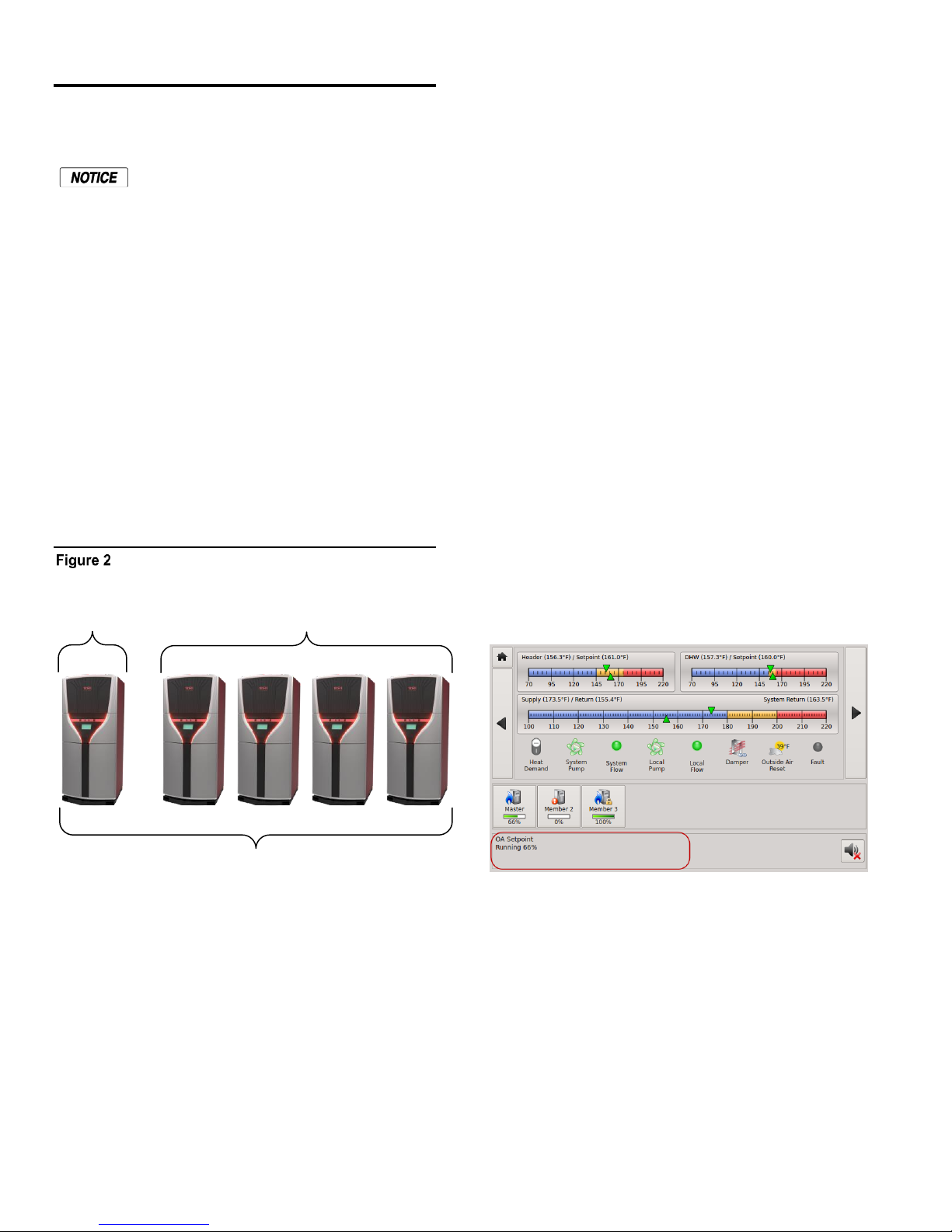
SETUP & OPERATION
1 to 16 Boilers
Member BoilersMaster
SETUP & OPERATION
Basic Multi Boiler System Operation
For boiler system setup/installations
please refer to the 2008 ASHRAE Handbook, CH12 or later
revision.
A basic multi boiler system typically uses boilers of the
same size and type. With HeatNet, this includes (1) Master
and (1-15) Member boilers. The boilers are connected
together using an H-Net communications cable effectively
creating (1) boiler. This allows the system heating BTUs to
be evenly distributed amongst all of the boilers.
The Version 1.6 HeatNet board requires Minibus
connections for FlexCore boilers with more than (1) heat
exchanger. The Minibus requires a serial data cable between
each HeatNet Control board. The first and last Heat
Exchanger must have the minibus terminated for the bus to
work properly. S1 would be placed in the ON position as
indicated below for the front and rear heat exchangers. The
jumper, JS1 must always be in the position indicated
(closest to S1). It is used for testing.
(LOCAL switch) closes, the system becomes operational
and will fire as many boilers as it needs to maintain the
header water temperature’s setpoint. See the DHW section
to fire using two setpoints.
When a boiler is to be fired in a multi boiler system (header
water temperature is below the heating band), the Master
checks the HeatNet boilers it has available. Then the Master
checks if a Lead Boiler is to be used (LEAD BOILER > 0).
The Master boiler then looks at which type of firing rotation
it has selected: LOFO, FOFO, TRUE (runtime), or MIXED.
In our example we will use the TRUE (runtime) rotation
since it is the default.
The Master now checks all of the runtimes to determine
which boiler has the least runtime based on the MIN
RUNTIME setting in SETTINGS: FIRING MODE: The
MIN RUNTIME setting is the minimum runtime interval in
hours that is used to compare boiler to boiler runtimes.
Once the boiler designated to fire has been determined, the
Master sends the command over the H-Net cable to fire that
boiler and resets the ADD BOILER delay timer to prepare
for the next boiler to fire. If the header water temperature is
still below the heating band and the ADD BOILER delay
timer has expired to zero, the process is repeated until the
header water temperature enters the heating band.
Basic multiple boiler system
A basic multi boiler system can be configured using the
boiler menus to create custom systems/features. These
features are best described in the section: Default Settings
& Menu Item Description. Along with these menu items
are hardware support for many auxiliary functions.
Once the system has been properly setup (all default menu
values used and H-Net addresses assigned), the system is
enabled by placing the REMOTE/LOCAL switch to the
LOCAL position on the Master boiler. All Member boilers
must have their respective switches in the REMOTE
position. When the Master boiler’s Heat Demand input
When a boiler receives a command to fire:
NOTE: Runtime messages are displayed in the lower left
corner of the Home Screen. See Section Messages for
descriptions.
1. The system pump relay is enabled and the H-Net
control displays “Waiting for Flow” until the flowswitch closes between J11A, 1 & 2 within the
programmed time (10 seconds default).
2. All elements in the interlock string, terminated between
J11A and J11B, must be closed before the sequence is
allowed to continue.
3. If all interlocks are closed, relay K5 is enabled to
command the combustion-air damper open (if used).
The H-Net control displays “Waiting for Damper to
Open” until the damper end switch closes.
4. Relay K6 is enabled energizing the local pump (if
used). The H-Net control commences its Waiting for
Page 12
Page 13

SETUP & OPERATION HeatNet Control V3
Flow” timer (adjustable 10–240 sec.). The flow switch
contact is checked on terminals J11B, 5 &6.
5. With all the interlocks closed, the boiler start relay K1
is enabled and energizes terminal 6 on the ignition
control. This signal is present on J5 Boiler Start
Operator. The control now displays “Waiting for Start
Sequence”
6. The ignition control begins its cycle and provides an
output signal from terminal 4 to the H-Net control J5
Blower. The H-Net control responds and provides an
output signal to the VFD which sets the blower to the
programmed pre-purge speed. If an Ametek blower is
used, a soft start speed is applied before the pre-purge
speed.
7. After air-flow is established the ignition control waits
for the air switch to close. When the air switch closes it
provides an input to terminal 7 and pre-purge timing
commences. The H-Net display indicates “Pre-Purge”.
8. When purge is complete the ignition control energizes
the pilot gas valve from terminal 8, and the spark
generator from terminal 10, beginning a 10-second Pilot
Flame Establishing Period (PFEP). The H-Net control
responds to J5 Pilot Valve and provides an output
signal to the VFD which sets the blower to the
programmed ignition speed. The H-Net display
indicates “Pilot”.
9. At the end of the PFEP the spark generator is de-
energized. If the pilot flame is detected, by the UV
scanner, the ignition control energizes the main gas
valve from terminal 9 to J5 Main Valve. The H-Net
display indicates “Running 0%” (0% indicates PID
modulation signal is not being calculated yet).
10. If main-flame is detected the H-Net control holds the
burner at the low-fire rate for the MODULATION
DELAY time period. After this timer expires, the PID
allows the boiler to modulate and places the boiler into
the running state.
As boilers are added to the system settings in the
SETTINGS: ADAPTIVE MODULATION MOD: DROP
DOWN menu determines when the modulation rate drops
down to compensate for the newly added BTUs. For the
drop down to be active, one boiler needs to be running when
a new boiler is added (see: Introduction: The FLEXCORE
CK-SERIES H-Net Control: Master).
If all boilers are firing, the modulation rate is released to go
to 100%. If all boilers are not firing, the modulation is
limited to the MOD-MAX clamp value. The MOD-MAX
clamp is used to keep the boilers running as efficiently as
possible. The following Mixed Boiler System Operation:
Selecting Mixed Boilers section outlines this with examples.
NOTE: If the boiler is running as a stand-alone boiler or
is direct modulated (including the AA input),
the MOD-MAX clamp will also be in effect for
the ADD BOILER DELAY time. This is to
minimize thermal shock to the boiler.
Once the header water temperature is in the heating band,
only the modulation rate is used to achieve the target
setpoint. The system will maintain the setpoint until the load
demand increases or decreases.
As the load decreases, the header water temperature will
start approaching the top of the band. The PID now lowers
the modulation rate to the boilers, attempting to keep the
temperature within the heating band. If the system is
delivering too many BTUs, the water temperature will cross
the top of the heating band.
When the header water temperature first exceeds the top of
the heating band, the boilers are again checked for the one
with the most runtime. The selected boiler will turn off
immediately and a shed boiler delay timer will be loaded
with the delay time. This time will need to expire before the
next boiler will be stopped, but only if the header water
temperature remains above the heating band. This timer is
used to allow the header water temperature to return back
into the band when a boiler is stopped. When a boiler is
stopped there is a fixed rate of BTUs (Min Fire) that will be
removed (PID discontinuity to modulate from Min Fire to 0
BTUs on a boiler). The timer allows for this loss of BTUs.
This cycle will continue until the call for heat is satisfied or
the Warm Weather Shutdown feature is enabled.
Mixed Boiler Types Using
Priority Sets
Using the Basic Multi Boiler System Operation, a MIXED
boiler Priority method may be added to control condensing,
non-condensing, base load, or other boiler SETs in a system
together. These sets compose a system which provides for
optimal performance and economy. Having dedicated sets
of boilers gives the system engineer a tool to create many
different boiler systems.
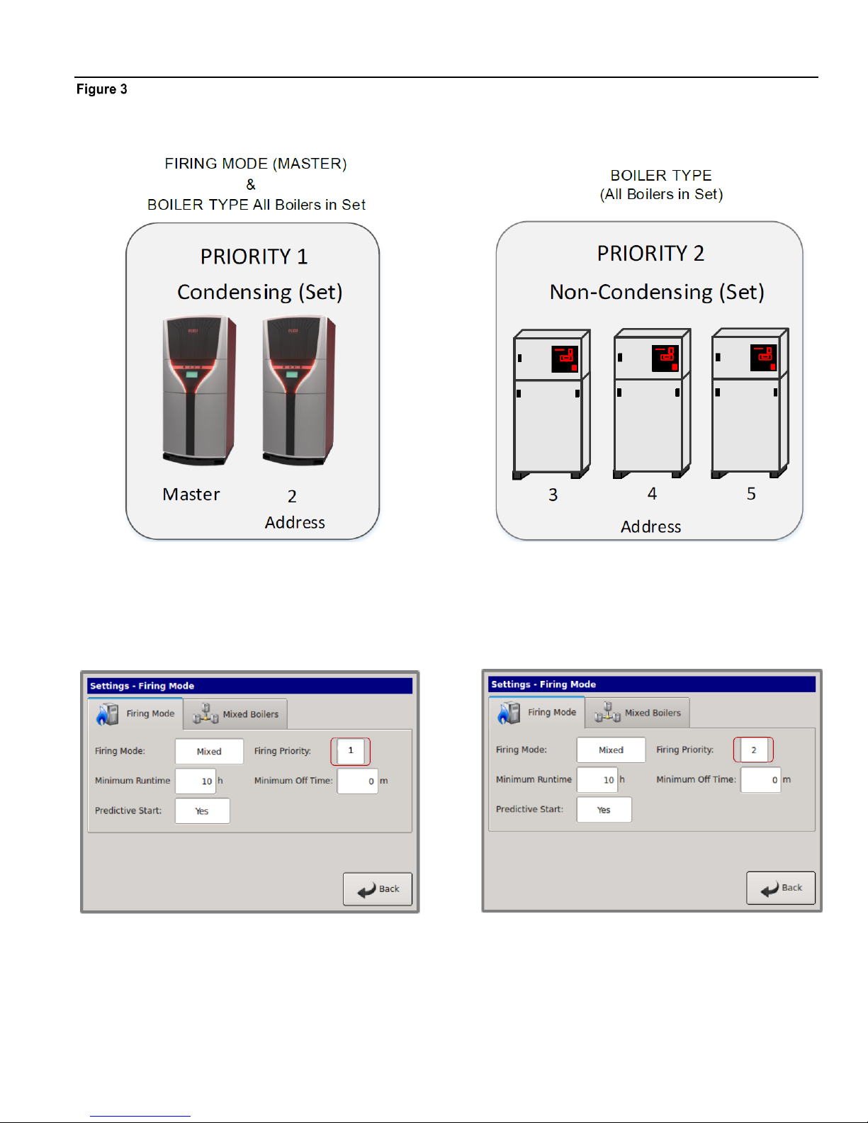
A boiler set can be constructed by simply setting the firing
Priority on each boiler (to be in a set) at the same priority.
Setting all (example) condensing boilers to the highest
Priority of 1, and then setting all (example) non-condensing
boilers to a Priority of 2, will create (2) sets of boilers, one
condensing and the other non-condensing. Once this is
done, the Priority 1 set of condensing boilers will have a
firing order that has a higher Priority and is independent of
the other non-condensing set with the lower priority. The
boiler set with the highest Priority can then be fired based
on a conditional settings menu. The lower Priority set will
follow.
Page 13
Page 14
SETUP & OPERATION
Mixed Boiler System Operation
Starting Boilers:
When a boiler is to be fired (water temp is below the heating
band), the Master checks the HeatNet boilers it has
available. The Master boiler then looks at which boilers are
returning Priority firing status (set on a boiler in:
(SETTINGS: FIRING MODE: FIRING PRIORITY:
PRIORITY: 1). If the Start condition for the Priority 1 set is
met (SETTINGS: FIRING MODE: MIXED BOILERS
FIRST (example), the Master or Member boiler that is
configured as PRIORITY 1, with the lowest runtime, will be
fired FIRST (example).
As long as the start condition for Priority 1 is met, all
boilers in the PRIORITY 1 set will fire based on runtime.
Once all boilers in the PRIORITY 1 set have fired, the
PRIORITY 2 set of boilers will fire based on runtime.
If the Start condition changes and/or is not met (such as
with: OA T or RET temp), the PRIORITY 2 set of boilers
will fire first/next based on runtime. This has the effect of
flipping the Priority of the sets.
Stopping Boilers:
When a boiler is to be stopped (water temp is above the
heating band), the Master checks the HeatNet boilers it has
available. The Master boiler then looks at which boilers are
returning Priority firing status (set on a boiler in:
(SETTINGS:FIRING MODE: MIXED BOILERS
LAST(example) If the Stop condition for Priority 1 is met,
the Master or Member boiler that are configured as
PRIORITY 1 with the highest runtime will be stopped LAST
(example). As long as the stop condition and SHED
DELAY time are met, all the remaining PRIORITY 1 set of
boilers, will stop based on runtime. If the Stop condition
changes and/or is not met (such as with: OA T or RET
temp), the PRIORITY 2 set of boilers will stop first/next
based on their highest runtime.
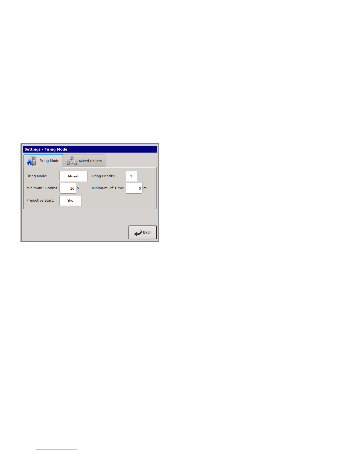
A boiler’s firing Priority can be designated as such in:
SETTINGS: FIRING MODE: FIRING PRIORITY:
PRIORITY menu on each boiler. A Priority of ‘1’ is the
highest priority, a ‘2’ the lowest (default is always 2).
Page 14
Page 15
SETUP & OPERATION HeatNet Control V3
Mixed Boilers: Example: Condensing/Non-Condensing
Page 15
Page 16
CONTROL METHODS HeatNet Control V3
In the example Mixed Boilers: Condensing/Non-
Condensing, condensing boilers and non-condensing boilers
are used, but other combinations may also be used. Another
example could use (2) small boilers and set them to
Priority 1 and then use (3) larger boilers and set them to
Priority 2. Using these Priority settings (with the conditions
menu), the small boilers can run first during the shoulder
months (Spring and Fall) and the larger boilers can fire last
during the colder Winter season (base loading set).
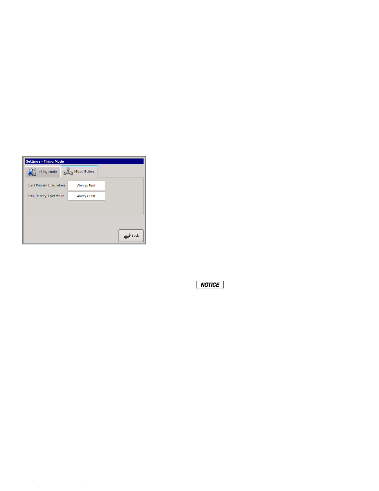
Before the MIXED method can be used, the firing mode on
the Master boiler must be set to MIXED. SETTINGS:
FIRING MODE: MIXED. Pressing the MIXED BOILERS
tab will enter the conditions menu. The START and STOP
conditions for starting and stopping the Priority boiler set
may be configured here. Temperatures are adjustable.
2. The Return water temperature is below 140F and
condensing occurs. (The Master’s system return water
would need to be used.)
3. The Outside Air Temperature is above a setpoint
determined by the system configuration. This setpoint
ensures that the more efficient condensing boilers run
first during shoulder months (Spring and Fall) when
minimal heating is required. Below this setpoint, larger
boilers should be brought on first to “base load” the
system.
4. Greater efficiency is required.
STOP FIRST
Condensing boilers may be configured to stop first (set to
PRIORITY 1) when:
The Return water temperature is above 140F and
condensing is minimized, thus leaving the larger lower cost
boilers running to carry the load.
1. The Outside Air Temperature is below an adjustable
setpoint determined by the system configuration. This
setpoint ensures that the larger non-condensing boilers
run during the coldest months when maximum heating
is required. Above this setpoint smaller condensing
boilers should be brought on first to run the system as
efficiently as possible.
Once the Mixed Boilers menu has been entered, the firing
order and stop order of the Priority 1 boiler set can be
selected based on up to (3) conditions in the conditional
settings menu. All conditional settings apply to the
Priority 1 boiler set. When the conditional settings do not
apply to the Priority 1 set, the conditional settings will apply
to the Priority 2 boiler set.
Note: If the firmware version for a HeatNet V2 board is at
least 3.47(or a version 3 board), the non-condensing boiler
may hold itself off from being added to the HeatNet
Master’s available to fire list. This would effectively keep
the non-condensing boiler from firing in a condensing
mode, but as a result, may not satisfy the system setpoint.
See: SETTINGS: HEAT EXCHANGER TEMP DISAB:
Start/Stop Priority Conditions
The following is an example using mixed
condensing and non-condensing boilers:
FIRE FIRST
Condensing boilers may be configured to fire first (set to
PRIORITY 1) when:
2. Maximum heating is required
START PRIORITY 1 SET
Selections (always the lowest runtime first):
The condensing boiler set (Priority 1) has a
higher Priority to fire when one of these
conditions is met. Values are adjustable.
FIRST: The condensing boilers (Priority 1) are always
started FIRST
OA T > 15F: The condensing boilers (Priority 1) are
started when the OA temperature is greater than the Mixed
Boiler Outdoor Air Temperature setting.
RET < 140F: The condensing boilers (Priority 1) are
started when the Return water temperature is less than the
Mixed Boiler Return temperature setting (This may not
applicable in most configurations since the local return
temperature on the Master is used to provide a difference
temperature across the heat exchanger. A System Return
sensor will be required. However, the return temperature
sensor may have been moved on the Master to provide
system return temperature on existing installations and is
still supported).
STOP PRIORITY 1 SET
Page 16
Selections (always the highest runtime first):
Page 17

CONTROL METHODS HeatNet Control V3
The condensing boiler set (Priority 1) has a
higher Priority to stop when one of these
conditions are met. Values are adjustable.
LAST: The condensing boilers (Priority 1) are always
stopped LAST.
OA T < 15F: The condensing boilers (Priority 1) are
stopped first when the OA temperature is less than Mixed
Boiler Outdoor Air Temperature.
RET > 140F: The condensing boilers (Priority 1) are
stopped first when the Return water temperature is greater
than the Mixed Boiler Return temperature. (This may not be
applicable in most configurations since the local return
temperature on the Master is used to provide a delta
temperature across the heat exchanger). A System Return
sensor will be required. However, the return temperature
sensor may have been moved on the Master to provide
system return temperature on existing installations and is
still supported).
Start/stop settings
Any combination of Start Conditions and Stop Conditions
can be used to optimize the mixing of condensing
(Priority 1) and non-condensing boilers (Priority 2) for best
performance/economy.
The default start setting always starts the condensing boilers
(Priority 1 example) first, except for the lead boiler setting.
The lead boiler will always start first if enabled, unless
there is a boiler already running (this includes a Member
boiler in LOCAL). The default stop condition setting always
stops the condensing boilers (Priority 1) last.
If prolonging the life of the heat exchanger(s) on noncondensing boilers is very important, consider starting the
condensing boilers (Fusion-Series) when the return water
temperature is below 140F.
The return water temperature sensor would
need to be moved from the Master’s return
inlet to the system return. The EXCHGR
DELTA may need to be adjusted in SETUP:
AUX FUNCTIONS: HEAT EXCHANGER
to prevent the Master from going to ½ input
when a high DELTA T is reached.
This method would lead to the non-condensing boilers
carrying the load when the system temperature stabilizes
above 140F, since non-condensing boilers will start first
with the Return water temperature is > 140F. The
condensing boilers can then be stopped first when the RET
water temperature is above the 140F. Remember, any
combination of the Start and Stop conditions may be applied
for best performance and economy in the system. Also, noncondensing boilers may be set to go offline when a return
temperature is too low using the SETUP: AUX
FUNCTIONS: HET EXCHANGER: TEMP DISAB menu.
Base load boilers can also be mixed in the same way as
condensing and non-condensing boilers. The base load
boiler(s) can be prioritized in one set (example, Priority 2)
and non-base load boilers (Priority 1). The non-base load
boilers can then be set to fire first and once they are all
firing, the base load boiler would fire.
To minimize the cycling of a large base load boiler, consider
using the stop condition. Change it to the OA T < 15F
(Outside Air Temperature) condition. This setting may be
used to stop the Priority 1 boiler set when the OAT drops
below the OA T setpoint, thus leaving the large base loaded
boiler on and shutting off the condensing boilers first. This
is also true when using the OA T setting to start the
Priority 1 boiler set when the OA T is above the start
setpoint. To use temperatures as start and stop conditions,
the system design temperatures must be known.
Selecting Mixed Boilers
There are a few factors to consider when choosing which
type of boilers to use in a mixed system. These factors need
to be considered when boilers are added or shed. When
BTUs are introduced into the system by adding boilers, the
amount of introduced BTUs should be smooth (linear). If
these factors are not considered, discontinuity in BTUs may
occur when boilers are added and as a result, short cycling
will occur.
1. Turndown: This is the ratio of minimum fire rate to
maximum fire rate: Example: a 20% minimum
modulation = 5:1 turndown (100%mod / 20% mod). A
(1) million BTU boiler = 200,000 BTUs minimum in.
2. MOD MAX CLAMP: This value determines the
maximum modulation % at which the boilers will fire
to, until all available boilers are firing.
3. Total System BTUs.
4. Desired Effective Turndown. This is the lowest
firing rate of the system relative to the maximum firing
rate of the system. The larger the value, the lower the
BTUs that can be delivered to a light load.
5. Piping.
Mixed System Type 1:
High System Turndown
The following examples are of mixed boiler systems with
high effective system turndown and fault tolerance built in.
When boiler types are the same, the system turndown is
limited to the boiler’s min input and fault tolerance is
always present. When the system has mixed boiler types,
consideration needs to be taken on what types can be mixed
properly to achieve a high system turndown and provide
some fault tolerance.
Page 17
Page 18
CONTROL METHODS HeatNet Control V3
System
MMBTU
Effective
Turndown
MOD
MAX
CK 5:1
24.0
20:1
70%
6000, 6000, 6000,
6000
12.0
20:1
70%
3000, 3000, 3000,
3000
6
20:1
70%
1500, 1500, 1500,
1500
System
MMBTU
Effective
Turndown
MOD
MAX
Priority 1
CK
5:1
Priority 2
CK
5:1
8.0
26:1
45%
1500, 1500
2500, 2500,
9.0
30:1
50%
1500, 1500
3000, 3000
9.5
30:1
50%
2500 2500
5000,5000
CK
Series
1500
2000
2500
3000
3500
4000
Max
Input
1500
2000
2500
3000
3500
4000
Min
Input
300
400
500
600
700
800
5:01
Mod
Max
1200
1600
2000
2400
2800
3200
80%
Mod
Max
1050
1400
1750
2100
2450
2800
70%
Mod
Max
900
1200
1500
1800
2100
2400
60%
Mod
Max
750
1000
1250
1500
1750
2000
50%
CK
Series
4500
5000
6000
7000
8000
9000
Max
Input
4500
5000
6000
7000
8000
9000
Min
Input
900
1000
1200
1400
1600
1800
5:1
Mod
Max
3600
4000
4800
5600
6400
7200
80%
Mod
Max
3150
3500
4200
4900
5600
6300
70%
Mod
Max
2700
3000
3600
4200
4800
5400
60%
Mod
Max
2250
2500
3000
3500
4000
4500
50%
Fault tolerance allows for one boiler in the Priority 1 system
to fail and any boiler(s) in the Priority 2 system to fail and
still provide near linear (continuity) BTU response when
adding boilers. This is illustrated in the following examples
using the Boiler System Response graphs.
The CK Series/Futera III/Fusion-Series Mixed Boiler
System (examples) is advantageous in providing low BTU
input for light loads and high BTUs for heavy loads. The
effective system turndown minimizes short cycling when
light loads are present by assigning smaller boilers to
Priority 1, running them first, and then stopping them last.
In order to achieve the high effective
turndown, smaller boilers are required
(plumbing considerations need to be
considered here due to differing flow/volume
characteristics through the large and small
boilers).
Example Systems:
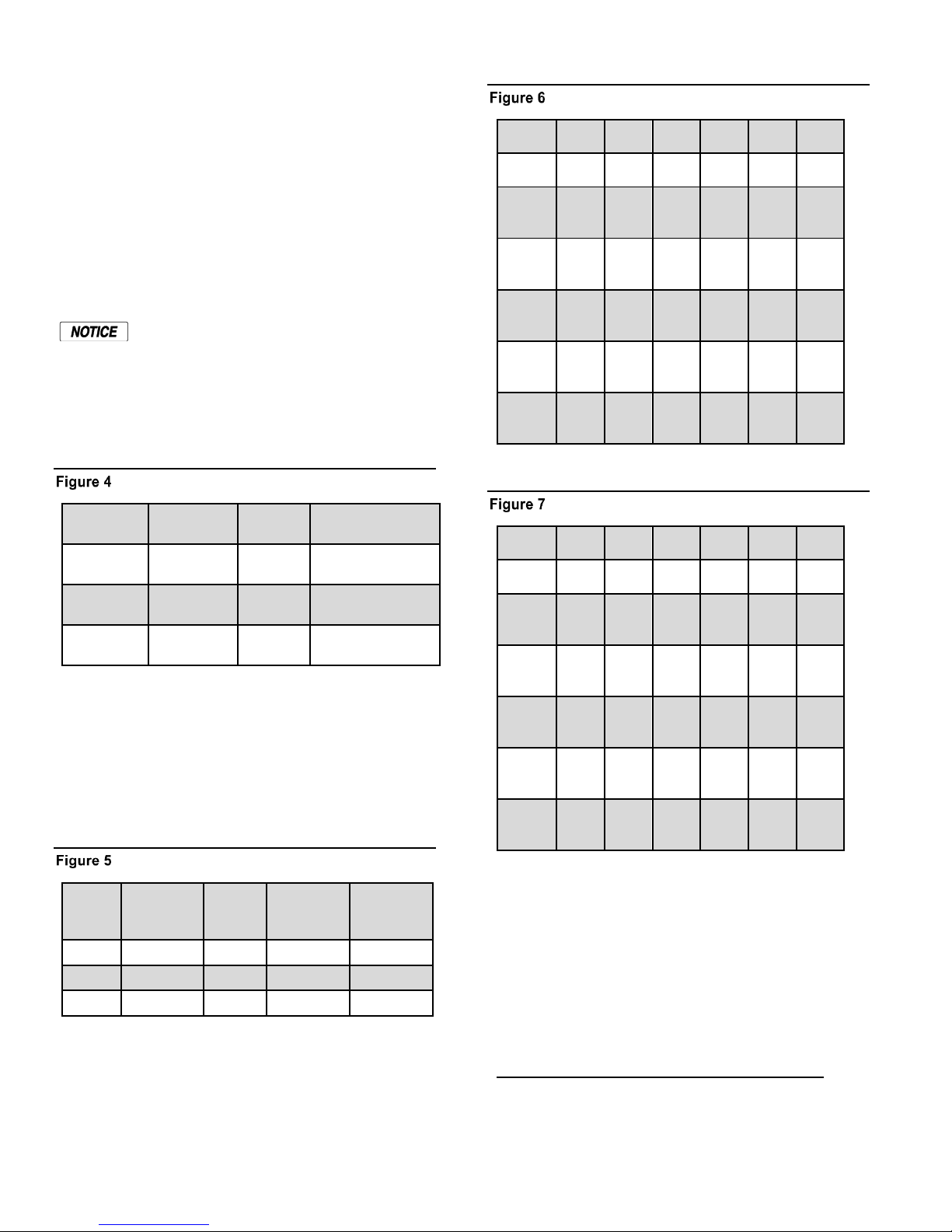
Non-Mixed Boiler System Examples
CK Series 1500 – 4000 Modulation Parameters
CK Series 4500- 9000 Modulation Parameters
With the traditional Non-Mixed boiler system, the effective
turndown increases by the turndown ratio for every boiler
added. The min fire rate is equal to the minimum BTUs that
can be delivered to the system.
Number of boilers * Turndown Ratio = Effective System
Turndown: 5 * 5:1 = 25:1.
Mixed Boiler System Examples
With the mixed boiler system, a lower minimum fire
rate/BTU can be delivered to the system by using small
boilers with larger boilers. This works in much the same
way as base loading.
When selecting the Priority 1 boiler(s) for a high effective
system turndown, the BTU Min Input is selected first. (See:
CK/Futera III/Fusion Boiler Btu Chart). Next, the MODMAX value of this Priority 1 boiler needs to be greater than:
Mod MAX % =
(Priority 1‘s Min Input + Priority 2‘s Min Input)
Max Input of the Priority 1 boiler
Page 18
Page 19
CONTROL METHODS HeatNet Control V3
The reason for this is to keep the continuity of BTUs linear
without a BTU bump (discontinuity) when boilers are added
or shed. The Mod Max % can be adjusted to the high side to
allow for tolerance (about 10%) as is indicated in the tables.
This is illustrated in the Boiler System Response 2 graph.
If redundancy is not required, the min inputs of the
Priority 1 boilers may be summed to lower the Mod Max %
value so smaller Priority 1 boilers can be used. The sum of
the min inputs would then need to be divided by the sum of
the Max Input of the Priority 1 boilers. The effect of this
would create a higher turndown. See: EXCEPTION NOTES:
Mod MAX % =
(((Priority 1 Min) * (#Priority 1’s)) + Priority 2 Min)
Max Input of Priority 1 boiler * (#Priority 1’s)
Example: (2) CK 1500, (2) CK 2500
Redundancy: (300 + 500)/1500 = 53%
No Redundancy: (300 * 2) + 500) / (1500*2) =36%
In this example, if “Redundancy” is used, the variable “# of
Priority 1’s” is not used.
EXCEPTION NOTES:
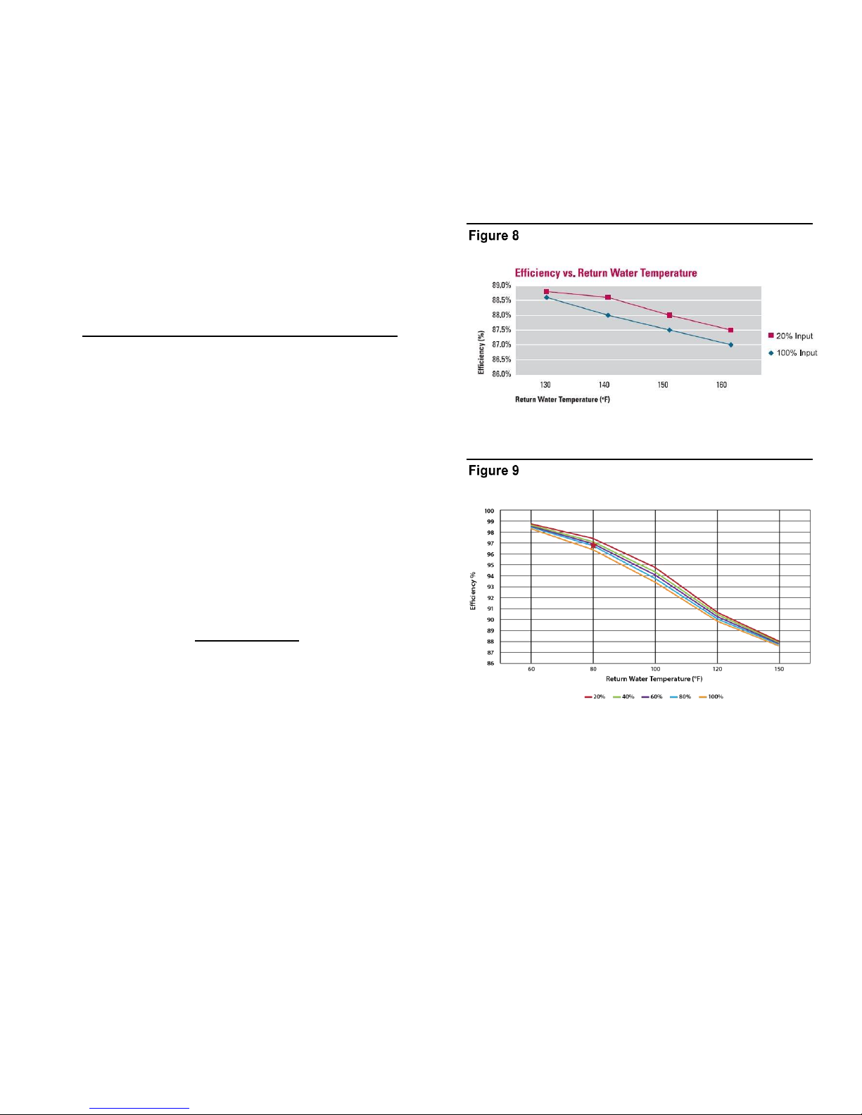
Non-Condensing Boilers chart can help illustrate how the
MOD-MAX value can affect the efficiency by limiting the
input until all boilers have fired. Non-condensing boiler
efficiency is relatively flat compared with condensing as
illustrated in the Typical Efficiency of Condensing Boiler
graph.
Typical Efficiency of Non-Condensing Boilers
Typical efficiency of Flexcore boilers
1. Mixing more than two different size/type boilers
becomes more complex than the scope of this manual
and is not recommended.
2. If using more than one Priority 1 boiler and the
calculated value is <
Priority 1Min * 2
Priority 1 Max Input
Use this result PLUS note 3 value as the
ModMax %.
3. Always add a few % (3-5%) to the calculated MOD
MAX % value to allow a guard band (tolerance).
4. If boilers are of different sizes, try to use larger Priority
2 boilers.
If the calculated Mod MAX % value is greater
than 99%, the combination cannot be used
since short cycling will occur.
Once the Priority 1 and Priority 2 boilers are selected, they
can be multiplied in each Priority set to achieve the desired
system design BTUs. If the # of boilers becomes a large
number, a Priority 1 boiler with a higher Min Input may
need to be selected.
In the Mixed Boiler System table line 1 example, (2) CK
1500s are set as Priority 1 and (2) CK 2500 boilers are set
as Priority 2. With a MOD MAX of 50% (Redundancy),
each 1500 can run to 750M (1500M total) before a 2500 is
called ON (Add Delay timer). Once both 1500s are running
and the 2500 is called on, all (3) boilers will drop to a sum
of 1500M BTUs: Taking this1500M value and dividing by
total M BTUS of the (3) boilers, 1500 +1500+1750 = 5500,
we get 27.27%. (.2727* 1500M) + (.2727* 1500M) +
(.2727* 2500M) or: 409M +409M + 681M = ~1500M and
operate at higher combustion efficiencies
While considering the MOD-MAX value, the lower the
MOD-MAX the greater the combustion efficiency since it
effectively limits the input rate. The Typical Efficiency of
Page 19
Page 20
CONTROL METHODS HeatNet Control V3
0.00
0.10
0.20
0.30
0.40
0.50
0.60
0.70
0.80
0.90
1.00
0
1,500,000
2,750,000
4,000,000
5,000,000
6,000,000
, %
System Load, Btu/Hr
Blr1 (750 MBTU)
Blr1+Blr2+Blr3 (2750 MBTU)
Blr1+Blr2+Blr3+Blr4 (4000 MBTU)
Blr1+Blr2 (1500 MBTU)
8,000,000
0.00
0.10
0.20
0.30
0.40
0.50
0.60
0.70
0.80
0.90
1.00
0
2,000,000
3,250,000
5,000,000
7,000,000
9,000,000
I n p t %
System Load, Btu/Hr
Blr 1+2 (2000 MBTU)
Blr 1+2+3 (9000 MBTU)
Blr 1+2+3 (3250 MBTU)
Blr 1 (750 MBTU)
750,000
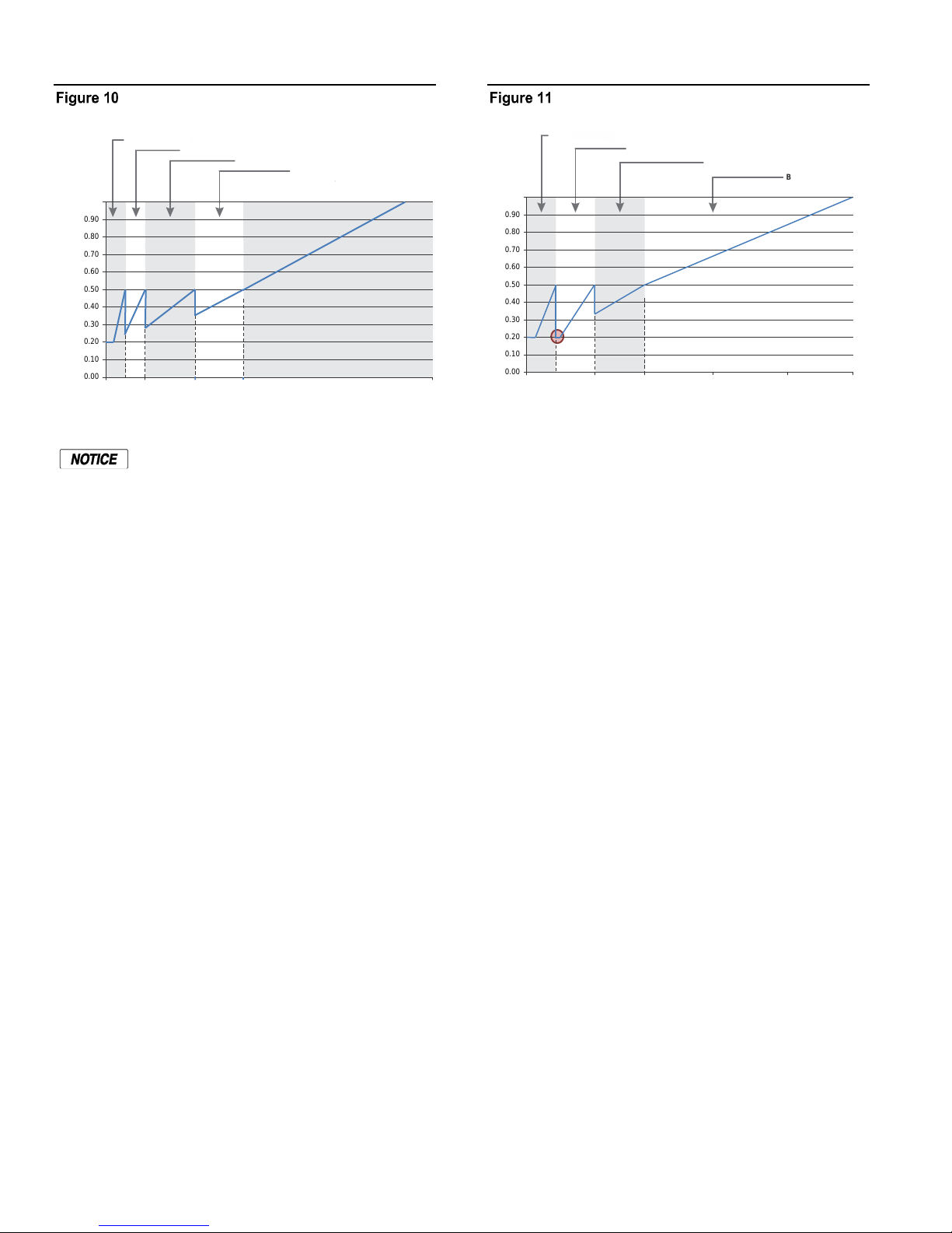
Boiler System Response 1
(2) CK 1500s, (2) CK 2500’s
When running non condensing boilers at low
input rates, the risk of condensing should be
considered.
The Boiler System Response 1 chart illustrates how each
boiler (in the example) is brought on and fires to 50%, drops
to a lower fire rate and then adds the next boiler (vertical
dashed lines). Once all boilers are firing, the modulation is
released allowing all boilers to fire to 100%.
Now, if (1) CK 1500 (one of the CK 1500s was taken
offline) were used with (2) CK 2500’s and the Mod-Max is
set to 50%, the CK 1500 would fire to 750 MBTUs and wait
for the CK2500 (Boiler System Response 2 graph). Now, the
minimum input rate would be 500M (CK 2500) + the 300M
(CK 1500) (already running, but dropped to low fire, but it
needs to go to 18.75%, when the CK 2500 starts), the total
being 800M. The turndown limits the boiler to running at a
minimum of 20%. With a 50% MOD-MAX clamp, there
would be 50 MBTUS more than needed that would be
added to the system when the CK 2500 fired.
The PID algorithm would then compensate for the
discontinuity (bump) in BTUs and the CK2500 would short
cycle. To compensate for this, the Mod Max percent would
need to be increased by 3%, but should be increased by at
least 5% to 55% to allow tolerance. 10% is a better
tolerance choice if room is available. This allows the load to
fluctuate without causing short cycles.
1500 * .55 = 825 MBTUS.
This new Mod-Max value will allow the sum of the low fire
BTUs of both boilers to fire at; 300 + 500 = 800 MBTUs
with room of 25 MBTUs, and prevent the short cycle
condition.
Boiler System Response 2
(1) CK 1500, (3) CK 2500, 50% Mod-Max
While a CK 1500 running with a CK 2500 is an acceptable
solution, it may not be an optimal choice unless (2) CK
1500s are used in the Priority 1 set and one is allowed to be
taken offline (for Redundancy).
A system employing this redundancy where (1) is allowed
to be taken offline is listed in the MIXED BOILER SYSTEM
chart. This system uses (2) CK 1500s and (2) CK 2500s.
Two of the CK 1500s are treated as one when adding the
min inputs of the Priority 1 set.
In summary, the system should be tuned using the boiler
selection charts and the MOD-MAX value. Since selecting
the Priority 1 boiler is integral to the fault tolerance of the
system, it is important to note any discontinuities in BTUs if
a Priority 1 boiler fails when multiple Priority 1 boilers are
used.
Mixed System Type 2:
Condensing/Non-Condensing
In the following examples, condensing boilers will be used
with non-condensing mass boilers. The reason for creating a
mixed system is primarily to control the system cost.
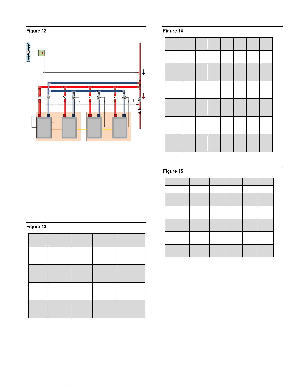
Note: In a mixed condensing/non-condensing system,
boilers with differing sizes, as outlined in the Mixed System
Type 1: High System Turndown section may also be used.
Page 20
Page 21
CONTROL METHODS HeatNet Control V3
Local Pump
Local Pump
MASTER
Condensing
MEMBER 1
Condensing
HNETHNET
Header Sensor
System Return Sensor
HNET
Local Pump
Local Pump
System Pump
MEMBER 2
Non-
Condensing
MEMBER 3
Non-
Condensing
Priority 1 Set Priority 2 Set
M
Combustion Air Damper
Outdoor Air Sensor
Outdoor Air
Sensor
System
MMBTU
Effective
Turndown
MOD
MAX
Priority 1
CK 5:1
Priority 2
MB/MW
7.5
25:1
55%
1500,
1500
4:1
1500, 1500,
1500
10.5
35:1
60%
1500,
1500
5:1
2500, 2500,
2500
18
30:1
55%
3000,
3000
5:1
4000, 4000,
4000
24
26:1
55%
4500,4500
5:1
5000, 5000,
5000
MB/MW
CB/CW
500
750
1000
1250
1500
1750
2000
Max
Input
500
750
1000
1250
1500
1750
2000
Min
Input
4:1
125
188
250
312
375
437
500
Mod
Max
80%
400
600
800
1000
1200
1400
1600
Mod
Max
70%
350
525
700
875
1.05
1220
1400
Mod
Max
60%
300
450
600
750
900
1050
1200
Mod
Max
50%
250
375
500
625
750
875
1000
MB/MW
2500
3000
3500
4000
5000
Max Input
2500
3000
3500
4000
5000
Min
5:1
500
600
700
800
1000
Mod Max
80%
2000
2400
2800
3200
4000
Mod Max
70%
1750
2100
2450
2800
3500
Mod Max
60%
300
450
600
750
900
Mod Max
50%
1250
1500
1750
2000
2500
Mixed Condensing/Non-Condensing Boiler
System
Note: The example drawings in this section are simplified.
They are meant to illustrate connections to the HeatNet V3
control. Only major components are illustrated. The system
engineer must ensure additional safeties, piping,
maintenance valves, and components meet code
requirements and safe operation.
Futera III/Fusion/ Boiler Btu Chart (MBH)
Futera XLF Boilers
Mixed Boiler System Examples
For the examples, the RBI FIII/Fusion series water heaters
will be used. These boilers are non-Condensing, fully
modulating, low mass, and HeatNet compatible.
If CB/CW Fusion boilers are substituted for the MB/MW
Futera III boilers, the efficiency is greatly increased due to
the condensing mode of these boilers. When using CB/CW
Fusion boilers, at lower firing rates, the combustion
efficiency is maximized by running the CB/CW Fusion
boilers from low to middle input rates. See: Typical
Efficiency of Condensing Boiler graph.
The Mixed Boiler System table show some examples of
mixed systems using different sizes along with Fusion
condensing (Priority 1) and Futera III non condensing
(Priority 2) boilers.
Page 21
Page 22

CONTROL METHODS HeatNet Control V3
Using the boiler charts and the examples used in: Mixed
System Type 1: High System Turndown, a mixed boiler
system can be designed. The Priority 1 boilers should be
setup so as to keep the non-condensing boilers from seeing
return water temperatures of less than 140F to ensure a long
heat exchanger life.
Normally, the Priority 1 boilers (Condensing) will be set to
fire first. Once all the Priority 1 boilers are firing, the next
boiler to fire (after the ADD BOILER timer expires) would
be the Priority 2 (non-condensing). If the return water
temperature has not come up to ~140F, the non-condensing
boilers could fire in a condensing mode. The ADD BOILER
delay timer would have to be set to a long enough period to
ensure this does not happen. Even then, the load may be too
great.
When running with a remote BMS setpoint, care must be
taken that an Outside Air reset setpoint (or other setpoint)
sent by the BMS is not set too low. If the BMS system is
controlling the setpoint close to the condensing temperature,
the return water temperature may never rise sufficiently to
keep boilers out of a condensing mode. HeatNet online is a
good way to monitor this scenario if suspected.
The following note will explain an alternative way (not
depending on the ADD BOILER DELAY) to keep noncondensing boilers from firing in a condensing mode.
HeatNet Master’s request as” unavailable”. As soon as
the return temperature reaches 140F, the boiler will
respond to the Master’s request that it is available to fire.
If the Master boiler is a version 2 board, the Master will
always transmit its Local Return temperature to all
boilers. If the Master is set to Priority 1 and all other
non-condensing boilers are set to Priority 2, the Master
should always remain on if there is a call for heat. This
requires that the Priority 1 boiler be set up to start first
and stop last. Using this method should always send a
valid return temperature to the Member boilers. This
method can also be used with a version 3 board, but a
system return sensor is preferred.
When this condition is in effect, the STATUS * screen will
indicate “blr offline”. While the boiler is in this “not
available” state, it can still be fired locally and failsafe is
still available.
SETUP: AUX FUNCTIONS: HEAT
EXCHANGER: SEND RETURN:
OFF The Master sends its return
temperature to all boilers
RETURN The Master sends its return
temperature to all boilers
NOTE:
If the firmware version for a HeatNet V2 board is at least
3.47(or a version 3 board), the non-condensing boiler
may hold itself off from being added to the HeatNet
Master’s available to fire list. This would effectively keep
the non-condensing boiler from firing in a condensing
mode, but as a result, may not satisfy the system setpoint.
In order to use this feature, the version 2 board would
need to monitor the system or local return temperature.
This can be done locally by setting SETUP: AUX
FUNCTIONS: HEAT EXCHANGER: TEMP DISAB:
RETURN if the there is no pump/valve limiting flow
continuously through the boiler. If there is a pump/valve
limiting the flow through the boiler, the SETUP: AUX
FUNCTIONS: HEAT EXCHANGER: TEMP DISAB: SYS
RET needs to be set. Then the Master boiler needs to set
SETUP: AUX FUNTIONS: HEAT EXCHANGER: SEND
RETURN: to which of its return temperatures it would
send to all boilers. These include the Local Return
temperature or the System Return temperature.
The Member’s menu “SETUP: AUX FUNCTIONS: HEAT
EXCHANGER: TEMP DISAB:” if set to RETURN or SYS
RET, will force the boiler to become unavailable to
HeatNet when the SETUP: AUX FUNCTIONS: HEAT
EXCHANGER: TEMP< 140F. This value is adjustable to
135F if a forced air fan is used. When the SYS RET or
RETURN temperature is <140F the boiler responds to a
SYS RET The Master sends the system
return temperature to all
boilers
SETUP: AUX FUNCTIONS: HEAT EXCHANGER:
LOW TEMP:
OFF No check is made to the return
temperature – boiler remains
online
RETURN Uses the boilers own return
sensor (No pump /valve
present)
SYS RETURN Uses the System Return temp
received from the Master Boiler
(its Local or System Return).
SETUP: AUX FUNCTIONS: HEAT EXCHANGER:
TEMP < 140F
This is the adjustable threshold temperature below
which the boiler will take itself offline.
(1) Degree F of hysteresis is provided so as to not
toggle offline<-to->online at the threshold temp.
Page 22
Page 23
CONTROL METHODS HeatNet Control V3
0.00
0.10
0.20
0.30
0.40
0.50
0.60
0.70
0.80
0.90
1.00
0
3,300,000
4,800,000
6,000,000
8,000,000
10,500,000
System Load, Btu/Hr
Blr 1+2+3 (3300 MBTU)
Blr 1+2+3+4 (4800 MBTU)
Blr 1+2+3+4+5 (10500 MBTU)
900,000
Blr 1 (900 MBTU)
Blr 1+2 (1800 MBTU)
Since the FIII boiler is non-condensing, the efficiency vs.
input is relatively flat. The MOD MAX value will not have
the same impact if the FIII non-condensing boilers were
placed in the Priority 1 set.
In a mixed condensing/non-condensing boiler system
example: (2) CK 1500s are set as Priority 1 and (3)
MB/MW 2500s are set as Priority 2. With a MOD MAX of
60%, each CK 1500 can run to 900M (1800M total) before a
MB/MW 2500 is called ON (Add Delay timer). Once both
CK 1500s are running and the CK 2500 is called on, all (3)
boilers will drop to a total of the 1800M BTUs. Taking this
1800M value and dividing by total M BTUS of the (3)
boilers The sum of the CK 1500, CK 1500, and CK 2500
would equal about 32.7% modulation: (.327* 1500M) +
(.327* 1500M) + (.327* 2500M) or: 490.5M +490.5M +
817.5M =~ 1800M and operate at higher combustion
efficiencies: 32.7% is roughly between the top two lines on
the Typical Efficiency of Condensing Boilers chart.
The 5:1 turndown of the boilers can allow the Mod Max
clamp to go lower, but return water temperatures need to be
taken into account to ensure the Priority 2 boilers don’t
enter a condensing state. Each system is different and
adjustments to the Mod Max value can be adjusted to
achieve the greatest efficiency.
So, for the first 1800 MBTU of load, the combustion
efficiency is maximized by running the (2) CK Series
boilers from low to middle input rates. Running the (2) CK
1500 boilers first, also has the added effect of minimizing
the return water temperatures of <140F from reaching the
non-condensing boilers.
In summary, the system should be tuned using the boiler
selection charts and the MOD-MAX value so that boilers
are brought on and fired in their respective efficiency curve
while maintaining continuity in BTUs. Since selecting the
Priority 1 boiler is integral to the fault/offline tolerance of
the system, it is important to note any discontinuities in
BTUs if a Priority 1 boiler goes offline when multiple
Priority 1 boilers are used.
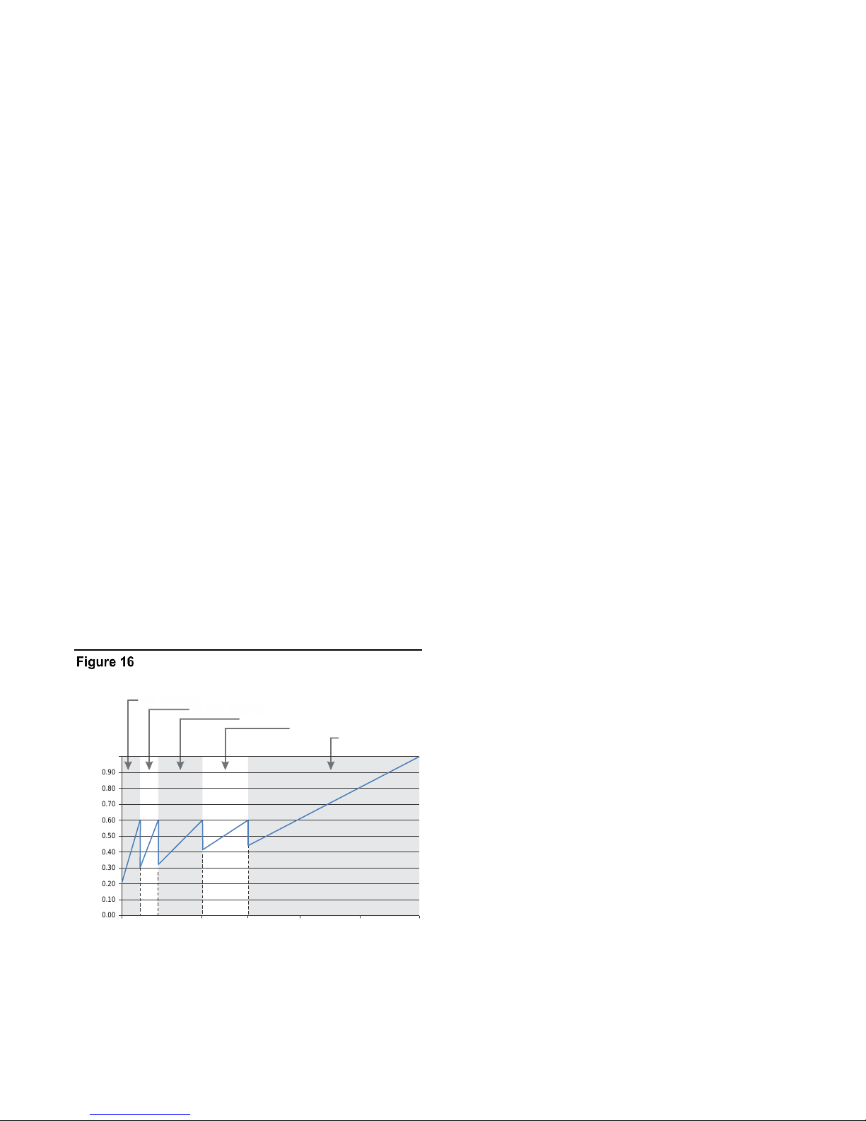
The Boiler System Response 5 chart illustrates how each
boiler (in the example) is brought on and fires to 60%, drops
to a lower fire rate and then adds the next boiler (vertical
dashed lines). Once all boilers are firing, the modulation is
released allowing all boilers to fire to 100%.
Boiler System Response 5
(2) CK 1500s, (3) MB/MW 2500s
Page 23
Page 24
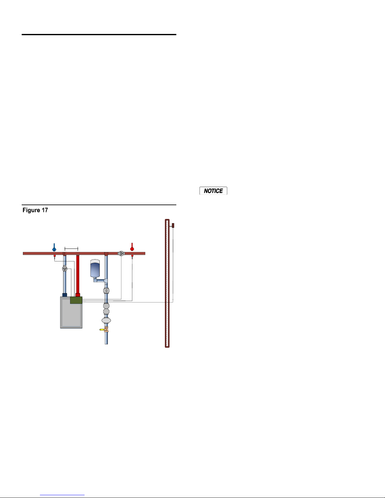
CONTROL METHODS HeatNet Control V3
MASTER
System Header Sensor
System Return
Sensor
Local Pump
System Pump
Expansion Tank
Backflow
Prevention
Pressure
Reducing
Ball Valve
System Pump
Supply Header Se nsor
HeatNet
Outdoor Air Sensor
MIN 3X PIPE DIAME TERS
MAX 10X PIPE DIAME TERS
BETWEEN CENTERS
WM
Water Meter
System Supply
System Return Sensor
Heating Control Methods
An overview of the (5) methods for controlling the FlexCore
CK -Series boiler are presented here. They are outlined in
more detail at the end of this section.
Heating Method 1
The first method is to use the FlexCore CK -Series boiler in
its stand-alone modulating method. This method uses a PID
algorithm to maintain a setpoint and is enabled using the
HEAT DEMAND input. Closing a relay contact or switch
across the HEAT DEMAND input will cause the Master
boiler to control all member boilers using H-Net.
A member boiler may also be controlled by the HEAT
DEMAND input (LOCAL mode). The member boiler will
then ignore commands from the Master and maintain its
LOCAL SETPOINT at the supply sensor.
Basic Single Boiler
Heating Method 3
The third method is to allow a remote 4-20 mA or 0-10
VDC signal to control the firing rate (modulation) of the
boiler using the 4-20 mA input, along with the 4-20 mA
REMOTE ENABLE input.
Heating Method 4
The fourth method turns the boiler ON and OFF @ 100%
modulation using the AA terminal.
Heating Method 5
The fifth method uses an RS485 digital communications
cable with the MODBUS protocol. The boiler is controlled
by writing and reading registers using MODBUS
commands. A bridge module may also be used to convert
BACnet or LonWorks protocols to MODBUS.
Short cycling may occur when a firing rate is
sent to a member boiler that would cause the
supply temperature to raise high enough to
trip the operating limit (low flow rate). After
the supply temperature falls, the boiler would
restart and the process may continue. A
member boiler would use its supply (outlet)
sensor to protect itself from short cycling by
limiting the firing rate coming from the
Master. This occurs in the event that the
member’s supply temperature increases above
the (OPERATE LIMIT- OPERATE LIMIT
BAND).
Note: The example drawings in this section are simplified.
They are meant to illustrate connections to the HeatNet V3
control. Only major components are illustrated. The system
engineer must ensure additional safeties, piping,
maintenance valves, and components meet code
requirements and safe operation.
Heating Method 2
The second method is to view the FlexCore CK -Series
boiler as two separate boilers or as a HIGH/LOW boiler
using T1 & T2.
Page 24
Operating Limit
When the Master boiler or an external control input is used
to control a member boiler (i.e. AA, T1-T2, 4-20 mA, HNet), a software operating limit on the member boiler will
be used to limit the maximum output of the member boiler.
This operating limit can be adjusted in the SETTINGS:
SETPOINTS: OPERATE LIMIT.
There is also an associated operating limit band that must be
set in conjunction with the operating limit to help prevent
this LIMIT from being reached. Its purpose, is to limit the
output of the boiler as it approaches the operating limit. If
the band is set to 10 degrees, then for every degree that it
approaches the operating limit, the maximum output will be
lessened by 10%. With a band of 20 degrees, for every
degree that it approaches the band, the maximum output will
be lessened by 5%. You can think of this operating limit as
a smart Aquastat which prevents the High Limit from
tripping. This method minimizes boiler short cycling when
using external inputs. The minimum setting is 1 degree and
effectively turns the limit band OFF. The default setting is
20F.
Page 25
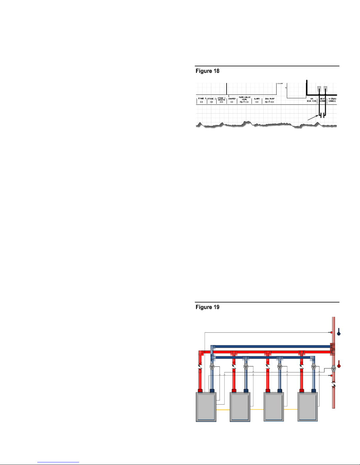
CONTROL METHODS HeatNet Control V3
MEMBER: Close to run at Local setpoint.
MASTER: Close to control all boilers and
run at System setpoint.
Local Pump
Local Pump
MASTER
MEMBER
1
HNETHNET
Space Heating
Loop
Header Sensor
MEMBER
2
MEMBER
3
System Return Sensor
HNET
Local Pump
Local Pump
System Pump
Input Priorities
The FlexCore CK-Series control inputs are prioritized so
that multiple levels of external control can be employed at
the same time. This means that if we are firing the boiler
with a low Priority input and a higher Priority input is called
for, the boiler will now fire at the higher Priority input.
When the high Priority input is removed, the boiler will
revert back to the lower Priority input that is still called.
Priority 1
The AA terminal has absolute control, and if used, will
always fire the boiler at 100% output, regardless of any
other input. The 4-20 mA input may be raised to this
Priority using SETTINGS: 4-20 mA INPUT:
PRIORITY.
Priority 2
The HEAT DEMAND input is the next, and provides the
means to operate the boiler in LOCAL MODE when an
external control is not present, has failed, or needs to be
enabled or disabled. A member can override the H-Net
commands using this input.
Priority 3
If a HeatNet (H-Net) Network cable is connected between
boilers, and one is configured as a MASTER (requires
HEADER sensor), then the MEMBER boilers will be
controlled over the network by the MASTER.
The AA terminal, the FAILSAFE mode active, 4-20 mA at
PRIORITY: HIGHEST, and the HEAT DEMAND input
(LOCAL) on a Member, are the only inputs that will
override the H-Net control.
Heat demand input
Master boiler
The MASTER boiler controls the system using a PID
algorithm. Once the boiler is started, a PID algorithm is
used to produce a modulation percentage value from 0100%. This percentage is converted to a PWM, (P)ulse
(W)idth (M)odulation signal by each boiler. The
temperature of the water is maintained by sending this
PWM signal to the Variable Frequency Drive, which in turn
controls the blower motor. Since the main fuel valve is airfuel coupled to the blower, the speed of the blower provides
the firing rate.
Member boiler(s)
Priority 4
The 4-20 mA/0-10VDC input in tandem with the 4-20 mA
REMOTE ENABLE input is next. Any signal over 4.02 mA
or 2.01VDC will start and operate the boiler if the
REMOTE ENABLE is closed.
Priority 5
The lowest Priority is using the boiler as (2) stages
HIGH/LOW. These are the T1 and T2 inputs.
Each of these control methods will now be explained in
more detail:
Heating Method 1
HEAT DEMAND
Closing a relay contact, switch, or jumper across the HEAT
DEMAND input will enable this method. This method
allows operation as a setpoint control. As a setpoint control,
the Master (defined by having a common system supply
header sensor), on the H-Net network can command the
boiler fire rate of all Member boilers. The Master can call as
many boilers that it has available (boilers are auto-detected
over the H-Net cable by the Master) to meet its SYSTEM
SETPOINT. The H-Net cable must be connected and will
cause the amber light on the communications board to flash.
The amber light indicates an H-Net Master is broadcasting
control information and a system heartbeat.
A Member (lacking a common system supply header
sensor) boiler may also be controlled by the HEAT
DEMAND input (LOCAL mode). The member boiler will
then ignore commands from the Master and maintain its
own LOCAL SETPOINT at its supply sensor. This can be
viewed as a manual override on a member boiler. Be sure to
observe the proper use of a Common System Damper (See:
AUXILIARY FUNCTION OPTIONS section) and any
system pumps or system common interlocks.
HeatNet Boilers Configured as Reverse Return
Page 25
Page 26
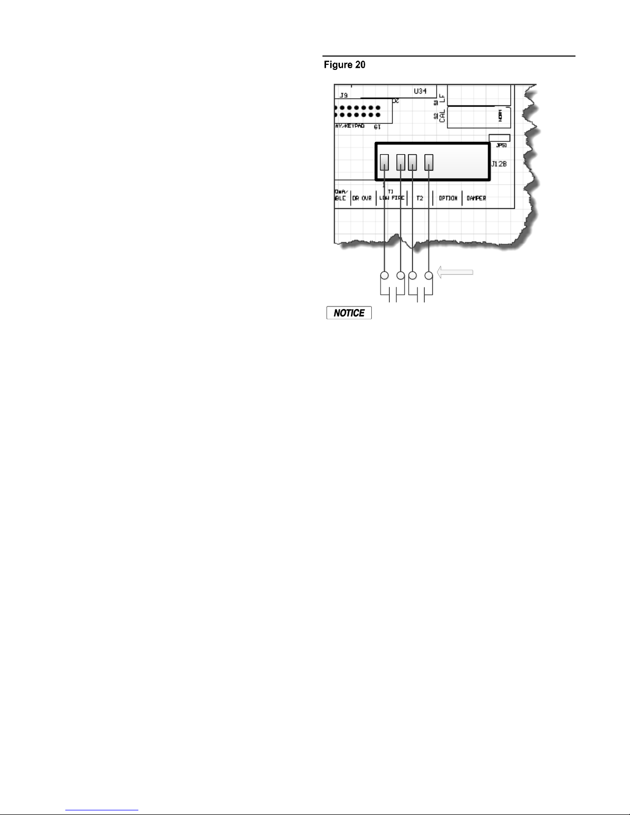
CONTROL METHODS HeatNet Control V3
Method 2
Stage Control Inputs:
T1 & T2
Features of the HEAT DEMAND input include:
1. The control is designed to predict when to start and
stop the boiler and keep the setpoint in, or as close to
the control band as possible. If PREDICTIVE START
is enabled, the boiler may start when it is in the band
and not below it. This will help to maintain a more
accurate temperature relative to the setpoint. See also:
SETTINGS: FIRING MODE: PREDICTIVE START:
to disable this feature.
2. The control can also use the Outdoor Reset feature.
This feature allows the setpoint to be changed
automatically based on the outside air temperature. If
this feature is used, the control input: OR OVR
(OUTDOOR RESET OVERRIDE), can be used to
override the Outdoor Reset feature and run from the
local setpoint. A contact closure on the ‘AA’ input can
also override this method.
3. The 4-20 mA setpoint control function works in
conjunction with this mode. This function translates a
4-20 mA control signal to a setpoint mapped between
50F and 220F. These (2) temperatures are adjustable to
provide a setpoint range. The minimum start current is
also adjustable between 3.71 and 5 mA. The setpoint
control feature is used in conjunction with the
REMOTE ENABLE input on J12A. This feature is
enabled in the SETPOINTS menu as:
SETPT SOURCE 4-20 mA
Stage control input
The maximum output of the boiler is based on
the MAX VFD setting in the calibration mode
and not the nameplate rating.
The AA, HEAT DEMAND (LOCAL) input, the H-Net, the
4-20 mA input will all override the stage control inputs.
Heating Method 3
4-20 mA Control
4. There is also support for a common system damper,
Heat Exchanger support, and starting the Master first
for common venting. For an overview of each of the
menu settings see: DEFAULT SETTINGS section.
Heating Method 2
STAGE Control T1-T2
The boiler can also be operated in 2 separate stages using
the inputs T1 and T2 inputs. Its intended use is with an
external stage controller with no analog or modulation
outputs.
Closing only one of these contacts tells the boiler to operate
at MINIMUM FIRE.
Closing the other contact will fire the boiler at MAXIMUM
output (the same rate as closing the AA input).
Placing a current source between the + and – 4-20 mA
inputs will allow remote control of the boilers firing rate.
An adjustable starting mA current signal here will start and
then fire the boiler at the minimum fire rate. See:
SETTINGS: 4-20 mA INPUT: CHANNEL MODE.
See section OPTIONAL FEATURES Using the 4-20 mA
input for extensive detail.
A 20 mA signal will fire the boiler at the maximum firing
rate. The input current signal is viewed as a percentage to
the boiler from 0 to 100% (0-20 mA). This means that a
20% (4mA) input signal is required to start the boiler, but
since the boiler is classified as having example: 4:1 turn
down ratio, the boiler can only be fired as low as 25% of
output. Any signal between 20% and 25 %, will fire the
boiler at the minimum fire rate. If the MINIMUM setting of
the boiler is set above the example: 4:1 turndown of 25%
(such as 33%), a control signal change between 25% and
33% will not change the boilers firing rate. Once the control
signal rises above the MINIMUM fire rate, the control
signal will then affect control of the boilers fire rate.
The AA terminal, the HEAT DEMAND, and the H-Net
NETWORK are the only inputs that will override the 4-20
mA input.
Page 26
Page 27
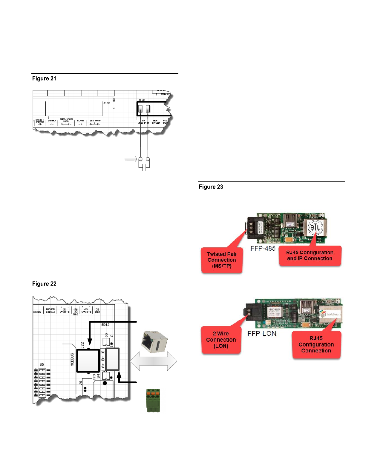
CONTROL METHODS HeatNet Control V3
Modbus Using
RJ45 Cat 5 cable
Modbus Using
shielded 3 wire.
Building
Management
Method 4: Close this AA contact
to run the boiler at High Fire.
Heating Method 4 AA Input
HIGH FIRE input Control: The AA input will fire the boiler
at HIGH fire (maximum output of the boiler). No other
inputs can override this input.
AA — High fire input
Heating Method 5
MODBUS communications
The System Setpoint Timer also needs to be loaded
periodically to allow the H-Net system to fallback to
Method 1 in the event communications is lost from the
Building Management System (BMS).
This feature can be turned off in SETTINGS:
COMMUNICATIONS: SETPOINT TIMER: OFF. If the
setpoint timer feature is set to ON, the SETTINGS:
COMMUNICATIONS: SETPOINT TIMER may be set to a
time that allows any write to a MODBUS register to reset
the setpoint timer as long as it occurs within that time. This
will reset the setpoint timer without writing the setpoint
timer register. So, periodically writing the setpoint register
will automatically reset the setpoint timer as long as the
write occurs within that time window.
Protocessor option
An optional BACnet or LonWorks bridge module can be
used to connect the MODBUS network to a BACnet or
LonWorks network.
Protocessor bridge module option
The fifth method uses an RS485 digital communications
cable with the MODBUS protocol to control the boiler
using the H-Net network. The Boiler or Boiler network will
run as in Method 1, but instead of the HEAT DEMAND
input, a software form of the HEAT DEMAND input is
used (40001: Boiler/System Enable/Disable). See:
MODBUS COMMUNICATIONS section.
MODBUS connections
This method allows enabling and disabling the boiler or HNet system, changing setpoints, reading boiler(s) status, or
temperatures remotely using digital commands. See the
section: MODBUS Communications.
Page 27
Page 28
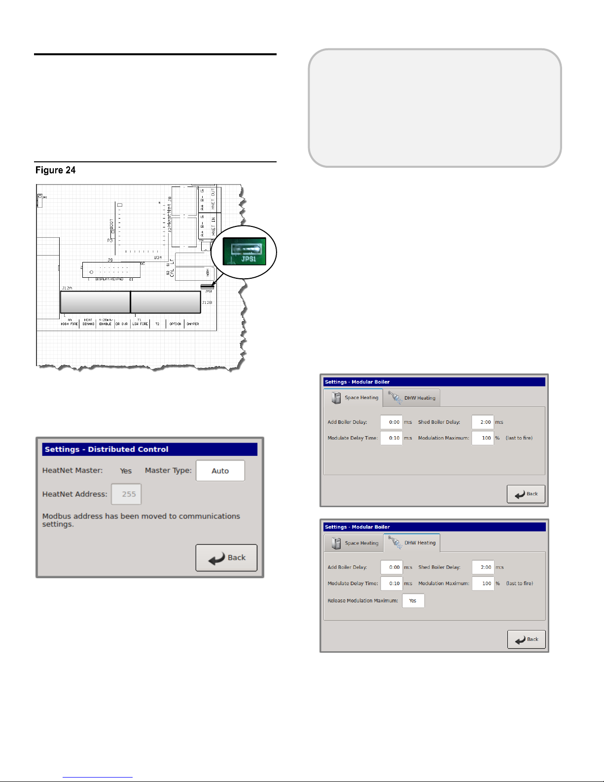
CONTROL METHODS HeatNet Control V3
Domestic Hot Water Methods
Domestic Hot Water control is supported using (6) methods.
When using the Domestic Hot Water methods, the wire
jumper, JPS1 on each control board providing Domestic Hot
Water, must be cut to limit the boiler’s maximum output
temperature to 200F. Refer to Figure 41 for control input
and Figure 49 for output locations.
Jumper JPS1
AUTO: will handle normal heating only applications. It
may also be used when individual boilers have tanks
connected and are controlled with the DHW BOILER?
set to LOCAL.
DHW: is for DHW applications without space heating.
Combination: Will allow combination Space and DHW
heating control of boilers by the Master.
The OR OVR input now functions in many of the
methods as a DHW Heat Demand input (except DHW
Heating Only method), but still retains the original OR OVR
functionality in AUTO, if the DHW menus are not used
(BOILER MODE? OFF). If the DISABLE TO CHANGE
message appears, remember to remove the any call for heat
including the OR OVR input.
When the MASTER TYPE is set to Combination the
MODULAR BOILER menu will contain (2) separate menu
tabs for controlling the ADD BOILER DELAY, SHED
BOILER DELAY, MODULATE DELAY, and the MOD
MAX for the SPACE HEATING and DHW HEATING.
This allows the independent control of boilers by the Master
for each of the (2) PIDs.
Note: Most of these methods use a separate PID control
for the DHW. This means that the Master boiler can be
used to individually control its own DHW tank and
provide space heating functionality at the same time.
A MASTER TYPE is required when using DHW. Its
setting is located under the DISTRIBUTED CONTROL
menu. Any time its setting is changed, a power cycle is
required. The menu choices are:
Page 28
Page 29
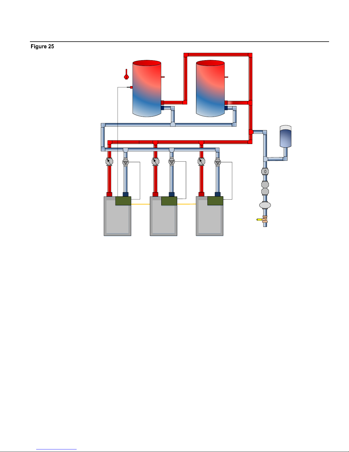
CONTROL METHODS HeatNet Control V3
MASTER
MEMBER 2
MEMBER 3
HNETHNET
Tank Sensor
DHW Sensor
Ball Valve
Expansion T ank
Pressure
Reducing
Cold Wate r
Makeup
Backflow
Prevention
Local Pump
Local Pump
Domestic
Supply
Domestic
Supply
WM
Water Met er
HeatNet
HeatNet
Local Pump
HeatNet
DHW Method 1: DHW Heating ONLY using a DHW MASTER and Member Boiler(s) Employing H-Net
Example DHW Only, Reverse Return Piping – Method 1.
DHW METHOD 1: DHW Heating ONLY using a DHW MASTER, Multiple Non-Condensing Boilers
A DHW Setpoint is maintained in the DHW tank based on the Master’s DHW Sensor. The system pump is enabled when the
boiler’s Heat Demand input is closed. Boilers are staged to meet the DHW Setpoint in the tank based on their runtime, and each
boiler will enable its local pump when it is running. The Master modulates the boilers to maintain the setpoint in the tank.
The cold water make up is piped into the supply piping to reduce the possibility of condensing in the boilers.
Page 29
Page 30
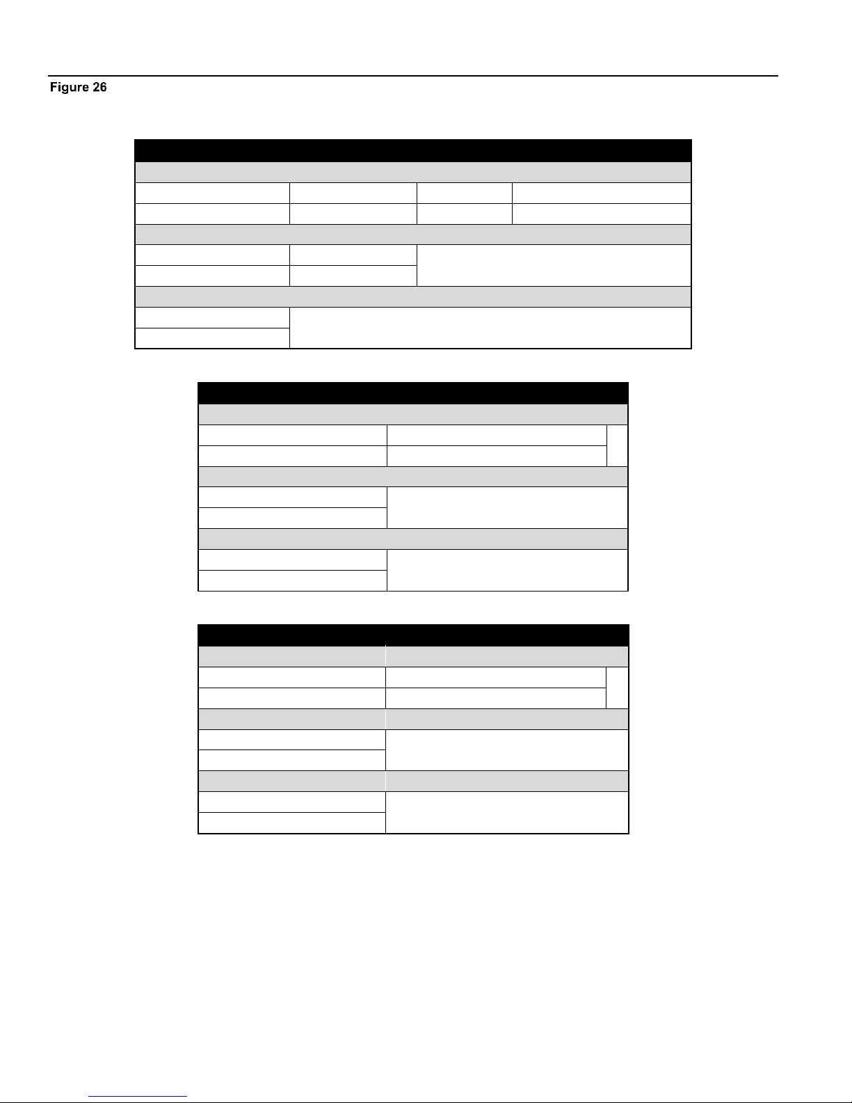
CONTROL METHODS HeatNet Control V3
Master (DHW Only)
Settings
DHW Use Sensor
HeatNet Address
Master Type
Combustion Air Damper
Yes
Automatic
DHW Only
Off
Inputs
Local/Remote
DHW Sensor
JPS1 Jumper must be cut to service DHW
Local
Yes - Tank
Outputs
Local Pump On
When Boiler Running
Member 2
Settings
HeatNet Address
Combustion Air Damper
2
Off
Inputs
Local/Remote
JPS1 Jumper must be cut to service DHW
Remote
Outputs
Local Pump On
When Boiler Running
Member 3
Settings
HeatNet Address
Combustion Air Damper
3
Off
Inputs
Local/Remote
JPS1 Jumper must be cut to service DHW
Remote
Outputs
Local Pump On
When Boiler Running
DHW Method 1 Quick Start Settings
DHW METHOD 1: DHW Heating ONLY Using a DHW MASTER and Member Boiler(s)
Note: The example drawings in this section are simplified. They are meant to illustrate connections to the HeatNet V3 control.
Only major components are illustrated.
The system engineer must ensure additional safeties, piping, maintenance valves, and components meet code requirements and
safe operation.
Page 30
Page 31

CONTROL METHODS HeatNet Control V3
This method requires a 10k thermistor connected to the
DHW Sensor input of a DHW MASTER, or a stand-alone
boiler, and a DHW tank. This method does not use a
HEADER sensor. The DHW temperature is maintained by
the space heating PID for backwards compatibility. With
this method the OR OVR input does not function as a DHW
enable and is not used. The Heat Demand input is used to
enable/disable DHW heating operations.
The system pump is enabled on the Master as long as the
Heat Demand input is closed. The Master’s DHW pump is
engaged only when there is a call for DHW heating by the
system. This allows for a DHW loop/buffer and A DHW
tank that can be heated using the Master’s DHW pump
(Reverse/Return only) or each boiler’s Local Pump/Valve
off of this loop/buffer.
DHW Page 1
Boilers are started as long as the tank’s water temperature is
below the (DHW SETPOINT – LOWER BAND). The first
boiler is started immediately. The next boiler(s) is started
after the ADD BOILER DELAY time expires. Boilers are
not added when the temperature is above the (DHW
SETPOINT – LOWER BAND) and below the UPPER
BAND. Once the UPPER BAND is exceeded, boilers will
shut off based on the SHED BOILER DELAY TIME.
Setting up this method is done via the menus in:
SETTINGS: DOMESTIC HOT WATER.
Connect a 10k thermistor from the DHW tank’s sensor
well to J10B terminals on the DHW MASTER, or
stand-alone boiler. Wire a pump or valve from the
DHW pump or the System pump (normally open) relay
contact to control flow of the heating water into the
tank’s coil or system loop.
The System pump will always be enabled as long as
the Heat Demand input is closed. The DHW pump
will be enabled whenever there is a DHW call for
heat.
A DHW call for heat is when the DHW temperature
is below the (DHW SETPOINT – LOWER BAND)
or when the DHW temperature is below the (DHW
SETPOINT + UPPER BAND) and boilers are
firing. After a DHW call for heat ends:
DHW Page 2
A. The pump will remain on during a post purge
pump cycle until the post purge timer expires.
1. Next, enter the DOMESTIC HOT WATER menu
on the Master boiler. In the BOILER MODE
selection, enter OFF. The Master uses this method
as a DHW system much like a space heating
system.
Member boilers may set the BOILER MODE to
LOCAL and go offline to perform secondary DHW
heating, but the Master setting must be set to OFF.
Setting the BOILER MODE to Combination using
this method may cause erratic operation and the DHW
pump to not be enabled.
2. Change the DHW SETPOINT to the desired target
temperature of the water in the tank. Once the control
determines there is a call for DHW, the DHW
SETPOINT is loaded and the Master boiler will target
the setpoint.
3. Now, change the LOWER BAND to the desired
temperature (DHW SETPOINT – LOWER BAND)
below which boilers are to be added. This setting
corresponds to the minimum water temperature
required in the tank. DHW heating will be initiated
when the DHW tank’s water temperature is below the
temperature (DHW SETPOINT – LOWER BAND).
How long the temperature of the tank stays below the
temperature (DHW SETPOINT – LOWER BAND) is
Page 31
Page 32

CONTROL METHODS HeatNet Control V3
used to determine when boilers are started along with
the ADD BOILER DELAY TIME.
4. Next, change the UPPER BAND to the desired
temperature (DHW SETPOINT + UPPER BAND)
above which boilers are to be shed. This setting is the
maximum tank temperature. Setting the SHED
BOILER DELAY TIME correctly will limit the
maximum tank temperature to the (DHW SETPOINT
+ UPPER BAND). Setting the SHED BOILER
DELAY TIME = 0 will shut off all boilers
immediately once the (DHW SETPOINT + UPPER
BAND) is exceeded.
5. Now, determine if the DHW priority is required by
the menu item PUMP PRIORITY?. Setting this
value to YES will turn OFF the system pump when
the DHW mode is active. Setting this value to NO
leaves the system pump on.
6. Select the amount of time for the POST PURGE of
the DHW pump. This is the time that the DHW pump
relay remains energized after the DHW SETPOINT
has been satisfied.
A. The pump will remain on during a post purge
pump cycle until the post purge timer expires.
B. Pump on the Master boiler functions as a global
pump.
7. Now, in order to be a Master boiler, it must have a
Header sensor. In method 1 DHW Only, we will
employ the DHW sensor (J10-A, 9 & 10) in this
system instead of a Header sensor? USE SENSOR in
this example will be set to YES. This will allow the
boiler to control the DHW tank or system loop
temperature as a Master boiler using the DHW sensor.
The upper and lower differential temperatures will
also be loaded.
8. The SHARING item is set to OFF, only boilers that
are not firing will be checked for runtimes and fired.
9. Set the LOCAL PUMP OFF value to NO. This will
leave the local pump on during a DHW heating cycle
(backwards compatibility). Setting this value to YES
will always keep the local pump off.
The Master’s DHW relay will remain on as long as
there are boiler’s firing and the DHW temperature
is below the (DHW SETPOINT + UPPER BAND).
Once all boilers are off and the DHW temp is equal
to or above the (DHW SETPOINT + UPPER
BAND), the DHW pump will begin its post-purge
time. If during this post-purge time the DHW temp
falls below the (DHW SETPOINT + UPPER
BAND), the DHW pump will remain on.
Setting this value to YES, will shut the local pump
off during a DHW heating cycle, but will keep the
local pump on for the LOCAL DELAY: 10s time
before shutting off. This LOCAL DELAY: time
can be adjusted in the next menu item by pressing
the down arrow again.
10. Press the DOWN arrow again and the menu item:
will be displayed.
Set the PURGE TO value to TANK. This will
purge the heat from the boiler into the tank or
system loop. This will be done using the DHW
pump after the DHW heating cycle is complete.
If the PURGE TO: is set to SPACE, once the
DHW cycle has completed, the Master will shut the
DHW pump off within a few seconds. The SPACE
setting should only be used only for combination
space and DHW heating.
Now in the,
SETTINGS: DISTRIBUTED CONTROL:
MASTER TYPE select DHW.
NOTE: JPS1 MUST be cut on all DHW boilers.
Page 32
Page 33

CONTROL METHODS HeatNet Control V3
Member 2
Cold Wate r
Makeup
Expansion T ank
Backflow
Prevention
Pressure
Reducing
Ball Valve
Local Pump
Member 3
Master
Domestic Hot
Water
Supply
Make
Up
Dual
Tank Sensor
WM
Water Met er
3-Way
Valve
DHW Valve
DHW Valve
Local Pump
Local Pump
DHW Sensor
System Pum p
Heating
Only
Combination
Failsafe
Heating
Combination
Failsafe
DHW
Outdoor Air S ensor
Outdoor Air S ensor
System Return
System Header Sensor
System Return Sensor
System Pum p
MIN 3X PIPE DIAMETERS
MAX 10X PIPE DIAME TERS
BETWEEN CENTERS
System Supply
DHW Sensor
3-Way
Valve
System Pum p
System Pum p
Supply Retu rn Sensor
HeatNet
Supply Hea der Sensor
HeatNet HeatNet
DHW Method 2: Failsafe Combination DHW and Space Heating with a MASTER
Boiler and Member Boilers Utilizing Valves (Master Type: Combination)
In this example the Master is not a DHW boiler.
DHW METHOD 2: Failsafe Combination DHW and Space Heating using a MASTER Boiler and Member boilers with
valves
In this method the Master simultaneously controls both space heating and DHW heating. The Master is piped to only service
space heating, and both members are piped to service space heating and DHW heating. The Master’s Heat Demand input
enables space heating by energizing the system pump and maintaining the Heating Setpoint at the System Header Sensor. The
Master’s OR OVR input enables the DHW heating, by maintaining the DHW Setpoint at the DHW Sensor located in the DHW
tank.
Boilers are staged to meet both the Space Heating Setpoint, and the DHW Setpoint based on their runtime. When a boiler is fired
to service a space heating demand it will enable its local pump, and when a boiler is fired to service a DHW demand it will enable
its local pump and enable its DHW valve to divert water to the tank. The Master modulates the boilers in order to maintain the
setpoints.
This method allows for a Member boiler to provide Failsafe mechanisms in the event the Master fails and stops communicating
to the Members. Member 2 is configured to provide failsafe space heating, and Member 3 is configured to provide both failsafe
space heating and failsafe DHW heating.
Page 33
Page 34

CONTROL METHODS HeatNet Control V3
Master (Space Heating Only W/Valves)
Settings
Master Type
HeatNet Address
DHW Use Sensor
Combustion Air Damper
Combination
Automatic
Yes
Off
Inputs
Local/Remote
OR/OVR
Header Sensor
System Return
DHW Sensor
Local
Jumper
Yes
Optional
Yes - Tank
Outputs
System Pump On
Local Pump On
When Boiler Enabled
When Boiler Running
Member 2 (Space Heating Or DHW, Failsafe Space Heating W/Valves)
Settings
HeatNet Address
DHW Boiler Mode
DHW Local Pump Off
Combustion Air Damper
HeatNet Failsafe
2
Combination
No
Off
On
Inputs
Local/Remote
JPS1 Jumper must be cut to service DHW
Remote
Outputs
System Pump On
Local Pump On
DHW Pump On
Failsafe Heating
When Boiler Running
DHW Call
Member 3 (Space Heating Or DHW, Failsafe Space Heating and DHW W/Valves)
Settings
HeatNet Address
DHW Boiler Mode
DHW Local Pump Off
Combustion Air Damper
HeatNet Failsafe
3
Combination
No
Off
On
DHW Use Sensor
System Pump Priority
Yes
No
Inputs
Local/Remote
OR/OVR
DHW Sensor
JPS1 Jumper must be cut to service DHW
Remote
Jumper
Yes - Tank
Outputs
System Pump On
Local Pump On
DHW Valve On
Failsafe Heating
When Boiler Running
DHW Call
DHW Method 2 W/Diverting Valves Quick Start Settings
DHW METHOD 2: Combination DHW and Space Heating Using a MASTER Boiler and Member Boiler(s) Employing
Diverting Valves
Page 34
Page 35

CONTROL METHODS HeatNet Control V3
DHW Pump
DHW Pump
Member 2
Cold Water
Makeup
Expansion T ank
Backflow
Prevention
Pressure
Reducing
Ball Valve
Local Pump
Member 3
Master
Local Pump
Domestic Hot
Water
Supply
Make
Up
Dual
Tank Senso r
WM
Water Met er
Local Pump
Outdoor Air S ensor
Heating
Only
Combination
Failsafe
Heating
Combination
Failsafe
DHW
System Pum p
System Return
System Heade r Sensor
System Return Se nsor
System Pum p
MIN 3X PIPE DIAMETERS
MAX 10X PIPE DIAME TERS
BETWEEN CENTERS
DHW Sensor
DHW Sensor
System Pum p
System Pum p
System Supply
HeatNet
Supply Head er Sensor
HeatNet
HeatNet
Supply Ret urn Sensor
DHW Method 2: Failsafe Combination DHW and Space Heating with a MASTER
Boiler and Member Boilers Utilizing Pumps (Master Type: Combination)
In this example the Master is not a DHW boiler.
DHW METHOD 2: Failsafe Combination DHW and Space Heating using a MASTER Boiler and Member boilers with
pumps
In this method the Master simultaneously controls both space heating and DHW heating. The Master is piped to only service
space heating, and both members are piped to service space heating and DHW heating demands. The Master’s Heat Demand
input enables space heating by energizing the system pump and maintaining the Heating Setpoint at the System Header Sensor.
The Master’s OR OVR input enables the DHW heating, by maintaining the DHW Setpoint at the DHW Sensor located in the
DHW tank.
Boilers are staged to meet both the Space Heating Setpoint, and the DHW Setpoint based on their runtime. When a boiler is fired
to service a space heating demand it will enable its local pump, and when a boiler is fired to service a DHW demand it will enable
its DHW pump. The Master modulates the boilers in order to maintain the setpoints.
This method allows for a Member boiler to provide Failsafe mechanisms in the event the Master fails and stops communicating
to the Members. Member 2 is configured to provide failsafe space heating, and Member 3 is configured to provide both failsafe
space heating and failsafe DHW heating.
Page 35
Page 36

CONTROL METHODS HeatNet Control V3
Master (Space Heating Only W/Pumps)
Settings
Master Type
HeatNet Address
DHW Use Sensor
Combustion Air Damper
Combination
Automatic
Yes
Off
Inputs
Local/Remote
OR/OVR
Header Sensor
System Return
DHW Sensor
Local
Jumper
Yes
Optional
Yes - Tank
Outputs
System Pump On
Local Pump
When Boiler Enabled
When Boiler Running
Member 2 (Space Heating Or DHW, Failsafe Space Heating W/Pumps)
Settings
HeatNet Address
DHW Boiler Mode
DHW Local Pump Off
Combustion Air Damper
HeatNet Failsafe
2
Combination
Yes
Off
On
Inputs
Local/Remote
JPS1 Jumper must be cut to service DHW
Remote
Outputs
System Pump On
Local Pump On
DHW Pump On
Failsafe Heating
When Boiler Running
DHW Call
Member 3 (Space Heating Or DHW, Failsafe Space Heating and DHW W/Pumps)
Settings
HeatNet Address
DHW Boiler Mode
DHW Local Pump Off
Combustion Air Damper
3
Combination
Yes
Off
HeatNet Failsafe
DHW Use Sensor
System Pump Priority
On
Yes
Yes
Inputs
Local/Remote
OR/OVR
DHW Sensor
JPS1 Jumper must be cut to service
DHW
Remote
Jumper
Yes - Tank
Outputs
System Pump On
Local Pump On
DHW Pump On
Failsafe Heating
When Boiler Running
DHW Call
DHW Method 2 W/Pumps Quick Start Settings
DHW METHOD 2: Combination DHW and Space Heating Using a MASTER Boiler and
Member Boiler(s) Utilizing DHW Pumps
Page 36
Page 37

CONTROL METHODS HeatNet Control V3
This Method highlights the flexibility of the HeatNet
system. It works much the same as DHW METHOD 1,
but also has the ability to provide space heating and
failsafe functions. With a three boiler system, and with
any one boiler down, the system can still provide space
heating and a DHW call seamlessly.
With this method the Master boiler will use two PID
controls to simultaneously maintain the DHW and space
heating setpoints. This method is determined by
SETTINGS: DISTRIBUTED CONTROL: MASTER
TYPE: Combination.
This method utilizes a 10k thermistor connected to the
DHW Sensor input and the HEADER sensor input of a
MASTER boiler. Setting up the DHW portion of this
method is done via the menus in: SETTINGS:
DOMESTIC HOT WATER. For information on setting
up the space heating portion of this method, Refer to Heat
Demand Control Method 1 located in the CONTROL
METHODS section.
When this method is used (due to use of the DHW sensor),
the OR OVR input functions as an enable/disable. This
allows the DHW heating function to be enabled or
disabled much in the same way as the Heat Demand input
for space heating.
The DHW pump is individually controlled on each boiler
that fires in DHW. The Master does not use its pump
globally when any DHW boiler is called. The Master only
engages its DHW pump if it was called to perform DHW
heating.
When using this method, a DHW band is also available in
the Home screen. The space heating band will be
displayed on the left and the DHW Heating band on the
right. The bands will operate in a split screen view.
When using MASTER TYPE: COMBINATION, the
Master may control DHW and Space Heating needs. If the
Master goes down or loses communication with the
Member, a Failsafe mode is available to provide temporary
heat.
The DHW Failsafe mode is active when a Member
boiler’s SETTINGS: FAILSAFE MODES: H-NET
COMMUNICATIONS LOST: is set to ON. When this is
set to on, normal DHW heating using the OR OVR or DHW
sensor is disabled, even though there may be a DHW call on
one of these inputs.
When the Master Boiler’s communication is lost, and
after 10 minutes of not being restored, the DHW inputs
become active. The boiler now enters a stand-alone mode.
The Heat Demand on that boiler becomes active and not
only runs to provide failsafe space heating, but DHW heat
as well. The STATUS screen will display H-NET LOST.
If a thermostat is used, the boiler will run to Method 5A
until the thermostat input removes the DHW call. If a DHW
temperature sensor is used, the boiler will modulate to
maintain tank temperature. The DHW Call always has
priority over space heating. A dual 10k sensor is available
that can be wired from one tank to two boilers.
The DHW Method 2 examples uses (3) boilers. The
Master controls the Space and Domestic needs, though it
is not a DHW boiler. Failsafe control is provided by
wiring the Member boiler to the tank sensor (dual sensor
is optional) and any other system control needs the
Member may require in its backup role. Then one of the
local DHW control methods can be used to implement
DHW heating.
One advantage to this configuration is that a BMS can
control the system through the Master. It can also monitor
system status through a central location (Master boiler) by
a BMS, or HeatNet Online. This failsafe method can also
be used in the Combination DHW/Space Heating
Simplified Drawing.
Set up the Master boiler first:
1. Connect a 10k thermistor from the DHW tank’s
sensor well to J10B terminals on the MASTER, and
connect a Header Sensor to the SYSTEM HEADER
input. Wire any pump or valve from the DHW Pump
relay’s (normally open) contact to control flow of the
heating water into the tank’s coil or DHW loop.
2. Now, set the SETTINGS: DISTRIBUTED
CONTROL: MASTER TYPE: to Combination.
This setting informs the HeatNet control that (2) PIDS
are to be used to control DHW and space heating.
3. There are two MODULAR BOILER menus, one for
space heating and one for DHW heating. These (2)
menus appear when the SETTINGS:
DISTRIBUTED CONTROL: MASTER TYPE is
set to Combination. The (2) Modular boiler settings
are located in the SETTINGS: MODULAR
BOILER: menu. Normally, there is only one, but
with (2) independent PIDs, the (2) heating setpoints
may behave differently due to their loads or for other
various reasons. These allow for separate ADD,
SHED, MODULATE DELAY TIME, and
MODULATION MAXIMUM settings for DHW
and space heating.
4. Next, enter the SETTINGS: DOMESTIC HOT
WATER menu. When prompted for BOILER
MODE enter OFF.
5. Change the DHW SETPOINT to the desired target
temperature of the water in the tank/ or DHW loop.
Once the control determines there is a call for DHW
heat, the DHW PID will target this SETPOINT.
Page 37
Page 38

CONTROL METHODS HeatNet Control V3
6. Now, change the LOWER BAND to the
desired temperature (DHW SETPOINT –
LOWER BAND) below which boilers are to be
added. This setting corresponds to the minimum
water temperature required in the tank. DHW
heating will be initiated by starting boilers
when the DHW tank’s water temperature is
below the temperature (DHW SETPOINT –
LOWER BAND).
7. Next, change the UPPER BAND to the desired
temperature (DHW SETPOINT + UPPER
BAND) above which boilers are to be shed.
This setting is the maximum tank temperature.
Setting the SHED BOILER DELAY TIME
correctly will limit the maximum tank
temperature to the (DHW SETPOINT +
UPPER BAND). Setting the SHED BOILER
DELAY TIME = 0 will shut off all boilers
immediately once the (DHW SETPOINT +
UPPER BAND) is exceeded.
8. Change the DHW priority menu item PUMP
PRIORITY. Setting this value to YES will turn OFF
the system pump when the DHW mode is active.
Setting this value to NO leaves the system pump on.
This time includes the DHW post purge of the DHW
pump/valve.
9. Go to the POST PURGE menu item. This is the time
that the DHW pump relay remains energized after the
DHW SETPOINT has been satisfied. Once the tank
has exceeded the DHW SETPOINT + UPPER BAND
temperature and this DHW boiler has shut off (DHW
SHED BOILER DELAY TIME), the post purge time
will begin.
10. Now, go to USE SENSOR Select YES. This
will allow the boiler to control the tank or
DHW loop temperature using the DHW sensor.
The upper and lower band temperatures will
also be loaded when set to YES.
11. The next menu is the SHARING menu. Sharing
determines what happens when a DHW boiler is
needed and none are available (all boilers are running
is space heating and DHW heating). This means the
Master needs to steal a space heating boiler that is
running or no more boilers can fire in DHW.
OFF Is first come first serve. If a Boiler is not
available because all boilers are firing, the
DHW firing algorithm waits until one becomes
available, even though at least one is running as
a space heating boiler. If a space heating boiler
is needed, a DHW running boiler cannot be
stolen for space heating. Space heating has
priority when DHW is trying to steal.
CYCLE The DHW algorithm can steal a space
heating boiler and fire it as a DHW boiler. The
space heating boiler stops and then restarts as a
DHW boiler. DHW has priority.
NO CYCLE The DHW algorithm can steal a boiler
that is already running as a space heating boiler.
Instead of shutting down the space heating
boiler, it does a hot swap, engaging the DHW
pump and leaving the local pump running or
shutting it off. Use this in conjunction with the
LOCAL PUMP OFF: and the LOCAL
DELAY: settings. DHW has priority.
12. Next is the LOCAL PUMP OFF menu. When a
DHW heating cycle begins, what to do with the local
pump/valve is determined:
NO The local pump/valve will remain running during
DHW heating.
YES The local pump will shut off with a delay
determined by LOCAL DELAY: seconds. This
allows the DHW pump/valve to prove before
shutting off the local pump.
Piping of the system will determine which setting
to use.
13. Go to the PURGE TO menu. After a DHW cycle
completes, the pump/valve can be selected to either
purge to the TANK, or to the SPACE for the duration
of the post purge time. This selection can use the
space to dump the heat from the boiler and not
overheat the DHW tank/load.
14. Set the HYB SENSOR = OFF. This sensor is
selectable for Method 5A only.
15. Finally, go to the BOILER MODE menu. If JPS1
has not been cut, the selection will appear grayed out.
Cut JPS1. Once this is done, set the BOILER MODE
to Combination. The MASTER boiler will control
the temperature in the tank using as many boilers as it
has available on H-Net along with any the space
heating needs. The boilers must be piped
appropriately for this method to function correctly.
Now set up the Member boiler(s).
BOILER MODE Set to Combination on MEMBER
boilers, only the MASTER boiler.
DHW SETPOINT This does not need to be set on
MEMBER boilers, only the MASTER boiler.
LOWER BAND This does not need to be on
MEMBER boilers, only the MASTER boiler.
UPPER BAND This does not need to be set on
MEMBER boilers, only the MASTER boiler.
PUMP PRIORITY This does not need to be set on
MEMBER boilers, only the MASTER boiler.
Page 38
Page 39

CONTROL METHODS HeatNet Control V3
POST PURGE This needs to be set on all boilers. All
boilers control their respective DHW
pump/valve when they are called to perform
DHW heating.
SHARING This can be set on any boiler and will
how boilers will cycle on/off when they are
called to perform DHW Heating.
LOCAL PUMP OFF This can be set on any boiler to
determine how the local pump/valve behaves
when called to perform DHW heating.
PURGE TO This does not need to be set on
MEMBER boilers, only the MASTER boiler.
HYB SENSOR: = OFF. This sensor is
selectable for Method 5A only.
NOTE: JPS1 MUST be cut on all boilers
providing DHW. Cutting JPS1 limits to
maximum temperatures to 200F.
Page 39
Page 40

CONTROL METHODS HeatNet Control V3
MASTER
MEMBER 2
MEMBER 3
HNET
HNET
Tank Sensor
Supply H eader Se nsor
Expansion T ank
Cold Wate r
Makeup
Local Pump
Local Pump
Domestic
Supply
Domestic
Supply
WM
HeatNet
HeatNet
HeatNet
Local Pump
DHW Method 3: DHW Heating Only, Using a Header Sensor Input
Example: DHW Only Using Header Sensor, Primary/Secondary – Method 3
DHW METHOD 3: DHW Heating ONLY using a Header sensor input, Multiple Boilers, Reverse Return.
In this method a Heating Setpoint is maintained at the Master’s System Header Sensor located in the DHW tank. The Master’s
Heat Demand input enables space heating and maintains the Heating Setpoint at the System Header Sensor. Boilers are staged to
meet the setpoint in the DHW tank based on their runtime, and each boiler will enable its local pump when it is running. The
Master modulates the boilers to maintain the Heating Setpoint at the header sensor located in the DHW tank.
Page 40
Page 41

CONTROL METHODS HeatNet Control V3
Master
Settings
Master Type
HeatNet Address
Combustion Air Damper
Automatic
Automatic
Off
Inputs
Local/Remote
Header Sensor
JPS1 Jumper must be cut to service DHW
Local
Yes - Tank
Outputs
Local Pump On
When Boiler Running
Member 2
Settings
HeatNet Address
Combustion Air Damper
2
Off
Inputs
Local/Remote
JPS1 Jumper must be cut to service DHW
Remote
Outputs
Local Pump/Valve On
When Boiler Running
Member 3
Settings
HeatNet Address
Combustion Air Damper
3
Off
Inputs
Local/Remote
JPS1 Jumper must be cut to service DHW
Remote
Outputs
Local Pump/Valve On
When Boiler Running
DHW Method 3 Quick Start Settings
DHW METHOD 3: DHW Heating ONLY Using a MASTER and Member boiler(s) Employing H-Net Space Heating PID.
Page 41
Page 42

CONTROL METHODS HeatNet Control V3
This method will control a tank temperature when the tank
temperature setpoint needs to be maintained for extended
periods with minimal cycling. Multiple boilers can be used
via the H-Net, as this method employs the same PID
algorithm as for space heating. SETTINGS:
DISTRIBUTED CONTROL: MASTER TYPE:
AUTO.
1. JPS1 must be cut on all boilers providing
DHW to ensure the maximum output
temperature of all boilers is limited to 200F for
DHW operation.
This Method is very similar to the DHW only
method, but:
A. The display will not indicate that it is a
DHW heating boiler.
B. The DHW Heating band will also not
be displayed.
C. The heating band will use the space
heating band and not the UPPER and
LOWER DHW heating band limits.
D. DHW settings are not used.
E. Set the SETTINGS: DISTRIBUTED
CONTROL: MASTER TYPE: to
AUTO.
F. This method is for backwards
compatibility.
2. Use the Heat Demand Control Method 1
located in the CONTROL METHODS section
on page 22. Instead of placing the Header
sensor in the Header pipe, place it in a well, in
the tank, or a DHW loop.
The temperature at which boilers are staged
ON, and then OFF is controlled by the
SETTINGS: SETPOINTS: HEAT BAND
differential. This can be understood by referring
to the INTRODUCTION section on the
MASTER in the beginning of this manual.
This differential has the added effect of heating
the tank above the tank’s setpoint temperature.
If the tank setpoint is set to 140F and the heat
band is set to 10F, then the tank temperature
will rise to 145F before the first boiler turns off
(setpoint =140F +/- heat band/2). With (2)
boilers running, the SHED BOILER DELAY
time could add to the tank temperature. So, to
ensure that all boilers are shut off at the upper
point of the heat band, set the SHED BOILER
DELAY time to 0 or other small value. This
will effectively turn off all boilers at the upper
heat band point of: (example) 145F.
Now, there is one more thing to consider, the
pump’s post purge time. Dumping the heat from
all boilers (that were running) using a pump
post purge cycle will have an effect on the
tank’s water temperature. Consider this when
establishing the local pump’s POST PURGE
TIME.
3. Connect the Local Pump relay contact on J13 to
enable the DHW pump. Set its post purge time
to dump the boiler’s heat into the tank when the
boiler shuts off. Be aware that this may heat
the tank above the upper heat band of the
setpoint temperature.
4. Enable the system by placing the
LOCAL/REMOTE switch on the Master to the
LOCAL position.
Page 42
Page 43

CONTROL METHODS HeatNet Control V3
DHW Method 4a: Space Heating with DHW Override of Setpoint on Master,
using an Aquastat
Example: DHW METHOD 4a Space Heating with DHW Override of Setpoint on Master, using an Aquastat, Primary
Secondary, Reverse Return
DHW METHOD 4a: Space Heating with DHW Override of Setpoint on Master, using an Aquastat, Primary Secondary,
Reverse Return
In DHW METHOD 4a, the Master’s Heat Demand input enables space heating by energizing the system pump and maintaining
the Heating Setpoint at the Master’s System Header Sensor. When the Aquastat located in the DHW tank calls for heat, the
system loop temperature is overridden with the DHW Setpoint. The system pump continues to run, and the DHW pump is
enabled to supply heat to the tanks until the Aquastat is satisfied.
Boilers are staged to meet the active setpoint based on their runtime, and each boiler will enable its local pump when it is running.
The Master modulates the boilers in order to maintain the active setpoint.
Page 43
Page 44

CONTROL METHODS HeatNet Control V3
Master
Settings
Master Type
HeatNet Address
Combustion Air Damper
Combination
Automatic
Off
Inputs
Local/Remote
OR OVR
Header Sensor
System Return
JPS1 Jumper must be cut to
service DHW
Local
Tank Aquastat
Yes
Optional
Outputs
System Pump On
Local Pump On
DHW Pump On
When Boiler Enabled
When Boiler Running
DHW Call
Member 2
Settings
HeatNet Address
Combustion Air Damper
2
Off
Inputs
Local/Remote
JPS1 Jumper must be cut to service DHW
Remote
Outputs
Local Pump On
When Boiler Running
Member 3
Settings
HeatNet Address
Combustion Air Damper
3
Off
Inputs
Local/Remote
JPS1 Jumper must be cut to service DHW
Remote
Outputs
Local Pump On
When Boiler Running
DHW Method 2 W/Valves Quick Start Settings
DHW METHOD 4a: Space Heating with DHW Override of Setpoint on Master Using an Aquastat
Page 44
Page 45

CONTROL METHODS HeatNet Control V3
This method is for controlling DHW utilizing a tank
thermostat connected to a Master boiler. This method
requires a thermostat input to the OR OVR. When the
thermostat contact closes across the input OR OVR
(J12A .7 & .8), the control will sense this closure and
override the space heating setpoint with the DHW
setpoint. SETTINGS: DISTRIBUTED CONTROL:
MASTER TYPE: AUTO.
This method is for backwards compatibility.
In this mode, the boiler will fire to the DHW
setpoint. The settings for space heating will be used
except for the addition of controlling the DHW
pump/valve by the Master boiler.
1. Wire the dry contact from the thermostat on the
tank to the input on J12A terminal 7 & 8 (OR
OVR). Also, at this time wire any pump or
valve from the DHW Pump relay (normally
open) contact (J13 terminals 16, 17, & 18) of
the Master to control flow of the heating water
into the tank’s coil.
2. Enter the DOMESTIC HOT WATER
MENU. Go to BOILER MODE and enter
OFF/AUTO.
3. DHW SETPOINT The setpoint should reflect the
temperature desired in the heating loop when a tank is
calling for DHW heat.
4. LOWER BAND This is not used.
5. UPPER BAND This is not used.
6. PUMP PRIORITY Setting this value to YES will
turn OFF the system pump when the DHW setpoint
override mode is active. Setting this value to NO
leaves the system pump on. This active period
includes the post purge of the DHW pump/valve.
7. Select the menu item POST PURGE. This is the time
that the DHW pump relay remains energized after the
DHW thermostat has been satisfied. Once the tank
has opened its thermostat, the system/local setpoint
will be reloaded and the post purge time will begin.
8. Select the menu item: LOCAL PUMP OFF: When a
DHW heating cycle begins, what to do with the local
pump/valve is determined:
NO The local pump/valve will remain running during
DHW heating.
YES The local pump will shut off with a delay
determined by LOCAL DELAY: seconds. This
allows the DHW pump/valve to prove before
shutting off the local pump.
Piping of the system will determine which setting
to use.
9. Select the menu item: PURGE TO. After a DHW
cycle completes, the pump/valve can be selected to
either purge to the TANK, or to the SPACE for the
duration of the post purge time. This selection can use
the space to dump the heat from the boiler and not
overheat the DHW tank/load.
10. Set the HYB SENSOR = OFF. This sensor is
selectable for Method 5A only.
Follow the same steps as used to program DHW
Heating using a Header Sensor INPUT. USE
SENSOR, select NO.
Page 45
Page 46

CONTROL METHODS HeatNet Control V3
MASTER
MEMBER
2
MEMBER
3
HNET
Local Pump
HNET
DHW Pump
DHW Pump
Tank Sensor
Local Pump
Supply Hea der Sensor
System Pum p
Cold Wate r
Makeup
Expansion Tank
Ball Valve
Pressure
Reducing
Backflow
Prevention
System Return Sensor
HeatNet
HeatNet
HeatNet
Domestic
Supply
Cold Wate r
Make Up
Domestic
Supply
Cold Water
Make Up
WM
Water Met er
MIN 3X PIPE DIAMETERS
MAX 10X PIPE DIAME TERS
BETWEEN CENTERS (TYP)
System Return
Sensor
System Heade r Sensor
Local Pump
System
Pump
System
Supply
System
Return
DHW Method 4b: Space Heating with DHW Override of Setpoint on Master,
using a DHW 10K Tank Sensor
Example: DHW Method 4b: Space Heating with DHW Override of Setpoint on Master, using a DHW Sensor, Primary
Secondary, Reverse Return.
DHW METHOD 4b: Space Heating with DHW Override of Setpoint on Master, using a DHW Sensor, Primary
Secondary, Reverse Return
In DHW METHOD 4b, the Master’s Heat Demand input enables space heating by energizing the system pump and maintaining
the Heating Setpoint at the Master’s System Header Sensor. The Master’s OR OVR input is jumped to enable DHW heating using
the DHW tank sensor. When the DHW tank temperature drops, a DHW heat demand is generated, and the system loop
temperature is overridden with the DHW Setpoint. They system pump continues to run, and the DHW pump is enabled to supply
heat to the tanks until the DHW tank is satisfied.
Boilers are staged to meet the active setpoint based on their runtime, and each boiler will enable its local pump when it is running.
The Master modulates the boilers in order to maintain the active setpoint.
Page 46
Page 47

CONTROL METHODS HeatNet Control V3
Master
Settings
Master Type
HeatNet Address
DHW Use Sensor
Combustion Air Damper
Combination
Automatic
Yes
Off
Inputs
Local/Remote
OR OVR
Header Sensor
System Return
DHW Sensor
JPS1 Jumper must be cut
Local
Jumper
Yes
Optional
Yes - Tank
to service DHW
Outputs
System Pump On
Local Pump/Valve On
DHW Pump On
When Boiler Enabled
When Boiler Running
DHW Call
Member 2
Settings
HeatNet Address
Combustion Air Damper
2
Off
Inputs
Local/Remote
JPS1 Jumper must be cut to service DHW
Remote
Outputs
Local Pump On
When Boiler Running
Member 3
Settings
HeatNet Address
Combustion Air Damper
3
Off
Inputs
Local/Remote
JPS1 Jumper must be cut to service DHW
Remote
Outputs
Local Pump On
When Boiler Running
DHW Method 4b Quick Start Settings
DHW METHOD 4b: Space Heating with DHW Override of Setpoint on Master Using a 10K Tank Sensor
Page 47
Page 48

CONTROL METHODS HeatNet Control V3
This method is for controlling DHW utilizing a 10k sensor
in the tank connected to DHW TANK (J10A, 9 & 10) of
a Master boiler. This method is only available on the
Master boiler since its purpose is to override the setpoint.
This method requires a jumper input to the OR OVR
(J12A 7 & 8), which acts like an enable. The control will
sense this closure and override the space heating setpoint
with the DHW setpoint when the DHW tank temperature
drops below the lower band of the DHW setpoint. All
boilers are started and stopped using the space heating
“Modular Boiler” settings. SETTINGS: DISTRIBUTED
CONTROL: MASTER TYPE: AUTO.
In this mode, the boiler will fire to the DHW
setpoint. The settings for space heating will be used
except for the addition of the Master Boiler
controlling the DHW pump/valve.
1. Wire the 10K Tank sensor to the Master on
DHW TANK (J10A, 9 & 10). Jumper the
input on J12A terminal 7 & 8 (OR OVR).
Also, at this time wire any pump or valve from
the DHW Pump relay contact (J13 terminals
16, 17, & 18) N/C, C, & N/O respectfully to
control flow of the heating water into the tank’s
coil.
2. Enter the DOMESTIC HOT WATER
MENU. Go to BOILER MODE and enter
OFF/AUTO.
3. DHW SETPOINT The setpoint should reflect the
temperature desired in the heating loop when a tank is
calling for DHW heat.
5. UPPER BAND This is not used.
6. PUMP PRIORITY Setting this value to YES will
turn OFF the system pump when the DHW setpoint
override mode is active. Setting this value to NO
leaves the system pump on. This active period
includes the post purge of the DHW pump/valve.
7. Select the menu item POST PURGE. This is the time
that the DHW pump relay remains energized after the
DHW demand has been satisfied. Once the tank has
reached temperature, the system/local setpoint will be
reloaded and the post purge time will begin.
8. Select the menu item: LOCAL PUMP OFF: When a
DHW heating cycle begins, what to do with the local
pump/valve is determined:
NO The local pump/valve will remain running during
DHW heating.
YES The local pump will shut off with a delay
determined by LOCAL DELAY: seconds. This
allows the DHW pump/valve to prove before
shutting off the local pump.
Piping of the system will determine which setting
to use.
9. Select the menu item: PURGE TO. After a DHW
cycle completes, the pump/valve can be selected to
either purge to the TANK, or to the SPACE for the
duration of the post purge time. This selection can use
the space to dump the heat from the boiler and not
overheat the DHW tank/load.
10. Set the HYB SENSOR = OFF. This sensor is
selectable for Method 5A only.
4. LOWER BAND This is not used.
Follow the same steps as used to program DHW Heating
using a Header Sensor INPUT. USE SENSOR, select Yes.
Page 48
Page 49

CONTROL METHODS HeatNet Control V3
MASTER
MEMBER
2
MEMBER
3
HNET
Local Pu mp
Local Pu mp
HNET
DHW Pum p
DHW Pum p
System Return
Sensor
Domestic Hot
Water
Domestic Hot
Water
Tank Sensor
Supply H ead er Se nsor
Local Pu mp
System Pump
System Re turn Sensor
Expansion T ank
Cold Wate r
Makeup
HeatNet
HeatNet
Supply
Make Up
Supply
Make Up
WM
Tank Sensor
DHW Sensor
DHW Sensor
HeatNet
System Pum p
System
Supply
System
Return
DHW Method 5a: Local DHW Tank Heating using a 10k Tank Sensor.
Example: DHW Heating to a Local Boiler’s Tank,– Method 5a
DHW METHOD 5a: Local DHW Tank Heating Override using a 10K Type II Tank Sensor.
In DHW METHOD 5a: Local DHW Tank Heating Override, the Master’s Heat Demand input enables space heating by
energizing the system pump and maintaining the Heating Setpoint at the Master’s System Header Sensor using the available
members. A Member boiler will enable its local pump when called to service a heating call by the Master. Each member has its
OR OVR input jumped to enable local DHW heating using its DHW Sensor. When a DHW tank sensor calls for heat, the local
boiler goes offline from the Master. The boiler then disables its local pump, and enables its DHW pump to service the local tank
until the tank sensor has been satisfied. Once the call for DHW heat has been satisfied, the boiler is placed back online for the
Master to service the main heating loop.
Page 49
Page 50

CONTROL METHODS HeatNet Control V3
Master
Settings
Master Type
HeatNet Address
Combustion Air Damper
Automatic
Automatic
Off
Inputs
Local/Remote
Header Sensor
System Return
Local
Yes
Optional
Outputs
System Pump On
Local Pump On
When Boiler Enabled
When Boiler Running
Member 2
Settings
HeatNet Address
DHW Boiler Mode
DHW Use Sensor
DHW Local Pump Off
Combustion Air Damper
2
Local
Yes
Yes
Off
Inputs
Local/Remote
OR OVR
DHW Sensor
JPS1 Jumper must be cut to service DHW
Remote
Jumper
Yes - Tank
Outputs
Local Pump On
DHW Pump On
Space Heating Call
DHW Call
Member 3
Settings
HeatNet Address
DHW Boiler Mode
DHW Use Sensor
DHW Local Pump Off
Combustion Air Damper
3
Local
Yes
Yes
Off
Inputs
Local/Remote
OR OVR
DHW Sensor
JPS1 Jumper must be cut to service DHW
Remote
Jumper
Yes - Tank
Outputs
Local Pump On
DHW Pump On
Space Heating Call
DHW Call
DHW Method 5a Quick Start Settings
DHW METHOD 5a: Local Tank Heating Using a DHW Tank Sensor
Page 50
Page 51

CONTROL METHODS HeatNet Control V3
This method is used to provide combination space heating
and DHW heating. The boiler may be stand alone or in a
HeatNet configuration. It is meant to fire an individual
boiler in a DHW heating priority mode when that boiler’s
local tank temperature has a call for DHW heat (tank
sensor’s temperature drops below the DHW Setpoint +
LOWER BAND). The boiler will stop space heating (if
running) and switch to DHW heating. The DHW
pump/valve will be engaged and the water temperature in
the tank will be maintained by the boiler at the DHW
setpoint. Once the tank temperature exceeds the Setpoint +
UPPER BAND temperature, DHW heating will stop and
the pump/valve’s post purge will start.
When a tank’s temperature sensor is connected directly to
a boiler and the BOILER MODE is set to LOCAL. The
boiler will go offline from HeatNet and service the DHW
needs of its local tank. If the boiler is running in space
heating mode, then the “SHARING” setting may be used
to determine how, or if, to shut down before starting a
DHW cycle. When the DHW cycle is complete (includes
the post purge time of the DHW pump), the boiler will go
back online with HeatNet and become available to fire.
During a DHW cycle the DHW setpoint will be loaded
along with the UPPER and LOWER BAND limits. Also,
the SETTINGS: DISTRIBUTED CONTROL:
MASTER TYPE: is set to AUTO.
When a 10k Type II sensor is used with this method, the
OR OVR input functions as an enable/disable. This allows
the DHW heating function to be enabled or disabled much
in the same way as the Heat Demand input for space
heating.
When using this method, a DHW band is also available in
the Home Screen. The space heating band will be
displayed on the left and the DHW Heating band on the
right. The bands will operate in a split screen view.
1. Connect a 10k thermistor from the DHW tank’s
sensor well to J10B terminals on any boiler. Wire a
pump or valve from the DHW pump or the System
pump (normally open) relay contact to control flow of
the heating water into the tank’s coil or system loop.
The System pump will always be enabled as long as
the Heat Demand input is closed and the SETTINGS:
PUMP PRIORITY is set to NO. The DHW pump
will be enabled whenever there is a DHW call for
heat.
A DHW call for heat is when the DHW temperature is
below the (DHW SETPOINT – LOWER BAND) or
when the DHW temperature is below the (DHW
SETPOINT + UPPER BAND) and boilers are firing.
After a DHW call for heat ends:
A. The pump will remain on during a post purge
pump cycle until the post purge timer expires.
2. Next, enter the DOMESTIC HOT WATER menu
on the Master boiler. Go to BOILER MODE and
enter LOCAL.
3. Change the DHW SETPOINT to the desired target
temperature of the water in the tank. Once the control
determines there is a call for DHW, the DHW
SETPOINT is loaded and the boiler will target the
setpoint.
4. Now, change the LOWER BAND to the desired
temperature (DHW SETPOINT – LOWER DHW
DIFF) below which boilers are to be added. This
setting corresponds to the minimum water
temperature required in the tank. DHW heating will
be initiated when the DHW tank’s water temperature
is below the temperature (DHW SETPOINT –
LOWER BAND).
How long the temperature of the tank stays below the
temperature (DHW SETPOINT – LOWER BAND) is
used to determine when boilers are started along with
the ADD BOILER DELAY TIME.
5. Next, change the UPPER BAND to the desired
temperature (DHW SETPOINT + UPPER BAND)
above which boilers are to be shed. This setting is the
maximum tank temperature. Setting the SHED
BOILER DELAY TIME correctly will limit the
maximum tank temperature to the (DHW SETPOINT
+ UPPER BAND). Setting the SHED BOILER
DELAY TIME = 0 will shut off all boilers
immediately once the (DHW SETPOINT + UPPER
BAND) is exceeded.
6. Change the DHW PRIORITY. Setting this
value to YES will turn OFF the system pump
when the DHW mode is active (when the DHW
pump is on). Setting this value to NO leaves the
system pump on.
7. Now got to the POST PURGE menu. This is
the time that the DHW pump relay remains
energized after the DHW SETPOINT has been
satisfied.
A. The pump will remain on during a post
purge pump cycle until the post purge
timer expires.
8. Now, go to the USE SENSOR menu and select
YES. This will allow the boiler to control the
local tank or DHW loop temperature using the
DHW sensor. The upper and lower differential
temperatures will also be loaded.
9. Got to SHARING and set it to OFF or CYLE
if the boiler is currently running in space
heating and needs to be shut down before
starting up in DHW.
If SHARING is set to NO CYCLE, a hot swap
will occur. A hot swap is when the boiler is
running in space heating mode and does not
Page 51
Page 52

CONTROL METHODS HeatNet Control V3
need to be shut down. The DHW pump will be
energized without the boiler stopping. Once the
DHW cycle has completed, the boiler will stop
and wait to be called again for either space
heating or DHW heating. A shutdown always
occurs after a DHW cycle completes.
10. Set the LOCAL PUMP OFF value to NO.
This will leave the local pump on during a
DHW heating cycle (backwards compatibility).
Setting this value to YES will turn off or keep
the local pump off.
Setting this value to YES, will shut the local
pump off during a DHW heating cycle, but will
keep the local pump on for the LOCAL
DELAY: 10s time before shutting off. This
LOCAL DELAY: time can be adjusted in the
next menu item by pressing the down arrow
again.
11. Set the PURGE TO value to TANK. This will
purge the heat from the boiler into the tank or
system loop. This will be done using the DHW
pump after the DHW heating cycle is complete.
If the PURGE TO: is set to SPACE, once the
DHW cycle has completed, the boiler will shut the
DHW pump off within a few seconds. The SPACE
setting is to be used only for mixed space and DHW
heating.
HYB SENSOR = OFF
SETTINGS: DISTRIBUTED CONTROL:
MASTER TYPE select AUTO,
DHW or COMBINATION.
NOTE: JPS1 MUST be cut on all boilers
providing DHW.
Page 52
Page 53

CONTROL METHODS HeatNet Control V3
System Heade r Sensor
MASTER
MEMBER
2
MEMBER
3
HNET
Local Pump
HNET
DHW Pump
DHW Pump
System Re turn
Sensor
DHW Sensor
OR OVR
Supply
Sensor
OR OVR
Supply Hea der Se nsor
System Pum p
HeatNet
HeatNet
Domestic
Supply
Cold Wate r
Make Up
Local Pump
Cold Wate r
Makeup
Expansion T ank
Domestic
Supply
Cold Wate r
Make Up
WM
Optional
Location
Optional
Location
Return Heade r Sensor
HeatNet
System Pum p
Tank Thermos tat
Tank Thermos tat
System
Supply
System
Return
DHW Method 5b: Local DHW Tank Heating using a Thermostat & Hybrid
Sensor.
Example: DHW Heating to a Local Boiler’s Tank, Movable Sensor Location – Method 5b
DHW METHOD 5b: Local DHW Tank Heating using an aquastat and a Hybrid Sensor.
In DHW METHOD 5b: Local DHW Tank Heating using an aquastat and a Hybrid Sensor, the Master’s Heat Demand input
enables space heating by energizing the system pump and maintaining the Heating Setpoint at the Master’s System Header Sensor
using the available members. A Member boiler will enable its local pump when called to service a heating call by the Master.
Each member has its OR OVR input connected to a local tank aquastat. This method allows the DHW Temperature Sensor to be
placed in many locations. This sensor is called the Hybrid Sensor. When the aquastat located in the DHW tank calls for heat, the
local boiler goes offline from the Master and services the DHW call. The Member then disables its local pump, and enables its
DHW pump to maintain the DHW Setpoint at the Hybrid Sensor location. Once the DHW aquastat has been satisfied, the boiler
is placed back online for the Master to service the main heating loop.
Member 2 is configured to use its Local Supply sensor when servicing DHW demands, and Member 3 is configured to use its
DHW sensor.
Page 53
Page 54

CONTROL METHODS HeatNet Control V3
Master
Settings
Master Type
HeatNet Address
Combustion Air Damper
Automatic
Automatic
Off
Inputs
Local/Remote
Header Sensor
System Return
Local
Yes
Optional
Outputs
System Pump On
Local Pump On
When Boiler Enabled
When Boiler Running
Member 2
Settings
HeatNet Address
DHW Boiler Mode
Combustion Air Damper
2
Local
Off
DHW Use Sensor
Hybrid Sensor
DHW Local Pump Off
No
Supply
Yes
Inputs
Local/Remote
OR OVR
JPS1 Jumper must be cut to service DHW
Remote
Tank Aquastat
Outputs
Local Pump On
DHW Pump On
Space Heating Call
DHW Call
Member 3
Settings
HeatNet Address
DHW Boiler Mode
Combustion Air Damper
3
Local
Off
DHW Use Sensor
Hybrid Sensor
DHW Local Pump Off
No
DHW
Yes
Inputs
Local/Remote
OR OVR
JPS1 Jumper must be cut to service DHW
Remote
Tank Aquastat
Outputs
Local Pump On
DHW Pump On
Space Heating Call
DHW Call
DHW Method 5b Quick Start Settings
DHW METHOD 5b: Local Tank Heating using a Hybrid Sensor
Page 54
Page 55

OPTIONAL FEATURES HeatNet Control V3
Method 5b can also be used in a hybrid mode on Member
boilers with a thermostat connected to the OR OVR input.
This will enable DHW heating, and be used instead of
having the 10k sensor’s temperature detect when DHW
heating is needed, but will use a selectable sensor instead
to maintain setpoint.
When the OR OVR input sees the thermostat close, the DHW
pump/valve will be engaged and remain energized as long as
the OR OVR input sees that the thermostat is closed. The
DHW setpoint along with the DHW heating band will then be
loaded. A steady temperature will now be maintained using
the HYB SENSOR setting in the DHW menu. This sensor
will control the water temperature at the sensor’s location,
enabling or disabling the boiler as needed until the OR OVR
input sees the thermostat open. Once the thermostat opens,
the DHW pump post purge will begin.
The difference between the settings of method 5a vs. method
5b is the “USE SENSOR” setting. 5a requires that the “USE
SENSOR” setting be set to YES, and the 5b “USE
SENSOR” setting be set to NO. The HYBRID SENSOR
setting must also be set in the 5b mode to the sensor where
temperature needs to be maintained. It must be set to OFF in
the 5a method.
Method 5a USE SENSOR = YES
HYB SENSOR = OFF
Method 5b USE SENSOR = NO
HYB SENSOR = SUPPLY, DHW,
RETURN
Each sensor selection/location has its advantages. Select the:
Supply sensor will limit the temperature/firing rate of the
boiler, but may not be sufficient for continuous demand or
speed in heating the tank. It is already available, so no
additional sensor is needed.
Return sensor will allow the boiler to run its supply
temperature up quickly, but may bounce off of the operating
limit band. This would heat the tank in the shortest time, but
may overheat the tank. It is already available, so no additional
sensor is needed.
DHW METHOD 6: DHW using Direct
Control
If the control’s SETTINGS: 4-20 mA input is set to
PRIORITY = HIGH the 4-20 mA signal, once brought above
the 4-20 mA starting current can be used to override any other
Heat Demand and direct modulate the boiler.
This can be set in menu: ADVANCED SETUP: 4-20 mA
INPUT. It allows a member boiler to be taken offline and
directly modulated by an external control.
If the Master is using it for heating and the ADVANCED
SETUP: 4-20 mA is set to PRIORITY= HIGH, an external
control can now output a 4-20 mA signal which will take over
the boiler’s fire rate and override all other heating demand
inputs. The external control would also need to open any
valves or turn on pumps. This is typically used for DHW
Control.
DHW Maximum Runtime
When a Combination system has a call for DHW heat and
services it for a time that is longer then designed, the DHW
may need to be locked out or held off for a predetermined
amount of time (retry).
Two settings are provided to control this situation: the
Maximum Runtime, and the Holdoff Time. The Maximum
Runtime is set to allow the DHW call to occur for the design
time of the system. If for some reason this time is exceeded,
the Holdoff Time setting goes into effect. The Holdoff time
can be set to a Lockout (the OR OVR input needs to toggle or
a power cycle to clear the Lockout), or a fixed amount of
boiler off time. If the fixed amount of Holdoff time is
selected, the DHW functionality will be cycled between the
boilers running for the Maximum Runtime, and stopped for
the duration of the Holdoff Time.
DHW sensor will allow the placement anywhere needed to
maintain that locations temperature. This is an additional
sensor that needs to be acquired.
A thermostat can be placed in a tank and connected to the OR
OVR input. (On Member boilers only, The Master uses OR
OVR already with DHW METHOD 4), When the thermostat
contact closes across the input OR OVR (J12A .7 & .8) on a
Member boiler, the control will sense this closure and
disconnect itself from HeatNet.
Page 55
Page 56

OPTIONAL FEATURES HeatNet Control V3
Fire Tube FII
Base Loading, Relay Control
The control has the ability to control (1) base load boiler
using the K8 Relay contacts on J4 pins 2 & 6. In order to
connect to this plug, (2) wires with pins are required and
inserted in J4. Base Loading via relay requires these (2) flying
leads (loose wires available from the factory) to be inserted
into J4, pins 2 & 6. These (2) wires then make up the
Normally Open contacts. This feature also can be used on
Master or Member boilers. The solid state relay K8, with
contact connections on J4.2 & J4.6 has a rating of: 0.1 to 1
Amp.
If the base load boiler is of the modulating type, a 4-20 mA
signal is also provided on J4 pins 1 and 5. Jumper shunt JS1
will then need to be set to 4-20 mA position. Two additional
wires (available from the factory) will need to be added to the
J4 pins at 1 & 5. Pin 1 is the + output of the 4-20 mA
transmitter, and pin 5 is the – output. This modulating control
signal is used to modulate the base load boiler along with the
HeatNet boilers in parallel. The ADAPTIVE MOD does not
function in lowering the modulation rate when the base load
boiler is added. The PID will adapt to the newly fired base
load boiler and lower its modulation rate when the increase in
water temperature is observed.
The Master boiler requires a heat demand input in order to
control a Base Load boiler connected to it. Though, the
Master boiler does not need to be running. This is to ensure
that the system pump and damper will be enabled for the
system. The System pump and Damper control are the main
reasons to connect the Base Load boiler to the Master.
A Member boiler does not need to be firing in order to enable
its Base Load boiler. Provisions for the Base Load boiler
should be checked to allow a system pump to run and any
dampers to open.
Enable the base load feature by setting:
1. SETTINGS: BOILER TYPE: OPTION to BASE
LOAD. This setting uses the OPTION Relay K8 (J4 pins
2 & 6) as control for a Base Load Boiler.
2. The SETTINGS: BASE LOADING: BOILERS: to 1.
Currently allows (1) base load boiler.
3. The START WHEN: & STOP WHEN: qualifier
condition to the method discussed below.
4. The DELAY TIME to the amount of time required after
the start qualifier condition has been met to start the
boiler.
Failsafe on the Master boiler will occur if there is a Heat
Demand input present, there are no available boilers to fire,
and the Master has failed.
Failsafe using the Base Load boiler from the Member is
automatic. Whenever the Member fails, the Base Load boiler
will be enabled as long as the Member can do so.
Base loading a Futera II boiler
Page 56
If a MINIMUM OFF time of the Base Load boiler is needed,
the Base Load boiler will share the MIN OFF TIME of the
boiler controlling it. If the base load boiler was running and
shuts off, the MIN OFF TIME will need to expire before the
boiler can start again. Once this time expires, the DELAY
TIME also needs to expire to start the boiler. This will help in
minimizing short cycle conditions and can be set at
SETTINGS: FIRING MODE: MIN OFF TIME.
Page 57

OPTIONAL FEATURES HeatNet Control V3
Preferred:
A modulating base load boiler that can accept a 4-20 mA
control signal such as the Futera series is preferred, or a nonmodulating base load boiler that is sized correctly to the If the
base load boiler is not of the modulating type, stopping the
Base Load boiler will require that the size of the Base Load
boiler in BTUs to be known relative to the H-Net boilers.
HeatNet boilers. Boiler selection is ideally; having more total
BTUs in the HeatNet boilers than total BTUs of the Base
Load boiler. This will prevent short cycling. Example: (4) 2
million BTU HeatNet boilers = 8 million BTUs and (1) 6
million BTU Base Load boiler.
When all (4) HeatNet boilers are running @ 95%, the Base
Load boiler is called on (demand is approx. 8 million BTUs).
As the Base load boiler comes on it introduces 6 million
BTUs and the HeatNet boilers modulate down to 25% for a
total output of 2 million BTUs and running at high efficiency.
The HeatNet boilers can now modulate to the load from 1.6
million BTUs (20% mod) to another 8 million BTUs.
Not Preferred:
Example of having a larger Base Load boiler that is not of the
modulating type: If there is a 6 Million BTU Base Load boiler
running with (3) 2 million BTU HeatNet boilers, a short
cycling situation will arise when the (3) 2 million BTU boilers
are running @ 95% and the Base Load boiler is called on. At
this point there is a need for approximately 6 million BTUs.
The (3) smaller boilers will then modulate down to low fire.
At this point, the (3) smaller boilers need to shut off or the
Base load boiler would need to shut off. There is no overlap.
A selection for stopping the boiler now needs to be
determined. Setting the Stop qualifier; Modulation to 40% or
a low fire rate will shut the Base Load boiler off and allow the
(3) smaller boilers to modulate up again (short cycle of the
Base Load boiler; Use the Delay Timer and Min OFF timer).
The Stop qualifier; Outside Air is above xxF may also be used
if the system design temperature is known. Then let the Base
Load boiler cycle off of its limits, whether a 2 stage, Hi/Lo, or
modulating boiler. The default setting is for the Base Load
boiler to stop first once the water temperature exceeds the top
of the heating band.
Example: Base loading relay
Page 57
Page 58

OPTIONAL FEATURES HeatNet Control V3
Setting up base loading
The base load boiler is controlled using a set of contacts to
enable it (location J4). Enabling/Disabling this relay contact
can be done using any combination of (3) qualifiers to start
the boiler and (4) to stop the boiler. These qualifiers are:
1. Modulation %:
a. START menu item: The relay contact will close
when the MOD % from the Master boiler exceeds
this value. SETTINGS:BASE LOADING: START
WHEN: MODULATION IS ABOVE
b.
STOP menu item
: The relay contact will open
when the MOD % from the Master boiler falls
below this value.
SETTINGS:BASE LOADING:
STOP WHEN: MODULATION IS BELOW
If the START WHEN MODULATION IS
ABOVE value is set to a value higher than the
SETTINGS: MODULAR BOILER:
MODULATION MAXIMUM, all boilers will
be firing before this modulation rate is reached.
This will ensure that all available boilers are
firing before the base load boiler relay is
enabled.
c. Setting the STOP WHEN MODULATION IS
BELOW to a % value slightly above the min fire
rate % of the system will ensure that the base load
boiler will stop before the first condensing boiler
stops. This is due to the Modulation rate being close
to the min modulation rate before the water
temperature exceeds the top of the heating band.
2. Outside Air Temperature:
a. START menu item: The relay contact will close to
enable the boiler when the OUTSIDE AIR read from
the Outside Air Temperature sensor (if equipped)
falls below this temperature. SETTINGS: BASE
LOADING: START WHEN OUTSIDE AIR IS
BELOW.
b. STOP menu item: The relay contact will open to
disable the boiler when the OUTSIDE AIR read
from the Outside Air Temperature sensor (if
equipped) rises above this value. SETTINGS:
BASE LOADING: STOP WHEN OUTSIDE AIR
IS ABOVE.
If the OUTSIDE AIR qualifier is used as the
Start and Stop qualifier, ensure that there is at
least a few degrees difference for hysteresis.
3. Return Water Temperature
a.
START menu item
: The relay contact will close
to enable the boiler when the RETURN IS
ABOVE read from the Return Water
Temperature sensor (if equipped) falls below
this temperature.
SETTINGS: BASE LOADING:
START WHEN RETURN IS ABOVE.
b.
STOP menu item
: The relay contact will open
to disable the boiler when the RETURN IS
BELOW temperature read from the Return
Water Temperature sensor (if equipped) rises
above this temperature.
SETTINGS: BASE
LOADING: STOP WHEN RETURN IS BELOW.
4.
ALWAYS FIRST
a.
STOP menu item
:
: The relay contact will open
to disable the boiler when the temperature
exceeds the heating band. This gives the result
of stopping the Base Load boiler First. Default
setting.
Delay time
The DELAY TIME is also included to hold off starting the
boiler until the delay time is met. Once the start condition
qualifier term is met, the DELAY TIME will start counting
down. When the time expires, the base load relay contacts
will close. SETTINGS: BASE LOADING: DELAY
TIME. It is adjustable in a range of: 0 to 60 minutes.
Base Load Failsafe
If:
1) There are no boilers available to fire (offline or
faulted).
2) There are no boilers in local override.
3) There is a call for heat.
The J4 Base Load relay will close.
If a boiler becomes available and needs to fire, the Base Load
boiler will remain firing until the temperature exceeds the
band. This is provided to keep the system from entering a no
heat situation.
Page 58
Page 59

OPTIONAL FEATURES HeatNet Control V3
Closing this contact enables
the 4-20mA/0-10VDC input
Using the 4-20 mA input
(OPTIONAL)
The 4-20 mA input is designed to operate per the ISA-50.1
standard. It will support Type 2, Type 3, and Type 4
Transmitter/Receiver circuits.
The Type 2 and Type 3 circuit may use the supplied +24VDC
and 24VDC RET connections (J10B) to power a remote
transmitter. The –ma terminal will need to have a jumper
connected to the adjacent 24VDC RET terminal to reference
the signal ground.
With the type 4 configuration, multiple boilers (up to 5), may
be connected in series using the –ma +ma –ma +ma scheme
(no jumper to 24VDC RET). This allows one 4-20 mA
transmitter to control multiple boilers. A free-floating 250
ohm resistor is viewed by the BMS (or external control’s) 420 mA transmitter across the + and –4-20 mA terminals with
this method.
Example: 4–20 mA connections
4–20 mA enable connection
The 4-20 mA input uses a 250 ohm sense resistor to convert
the current to a voltage from 1 to 5 volts DC for the control to
use. For this reason, a 1-5 VDC control voltage may also be
used across the 4-20 mA +/- input, but it still needs to supply
the necessary current, i.e. 20 mA. This resistor is located on
the bottom side of the control board. When a 4.02 ma signal is
sensed, the boiler will initiate a start sequence and fire the
boiler at its minimum setting if the REMOTE ENABLE input
is closed. This is typically 25% of the boilers output (4:1
turndown).
If the dip switch S6 is set to the 0-10 position (UP) See:
Figure 51, the 4-20 mA input will accept a 0-10 VDC signal.
The channel will also need to be setup in the menu:
SETTINGS: 4-20 mA INPUT: CHANNEL MODE. The
operating range will be from 2-10 VDC or twice what was
previously stated for the 1-5 VDC functionality. To convert a
0-10VDC signal to mA, divide by 2510 (ohms).
NOTE: Due to the inability of control voltage methods (1-5,
2-10 VDC) to reject noise and compensate for line loss, the
use of the 4-20 mA control current is recommended. The
control voltage methods may be less expensive, but are the
least stable. If using a 0-10VDC control signal, a source
current of 5mA is required.
If using a remote panel with a relay and a 4-20 mA transmitter
for operation, connect the 4-20 mA transmitter output from
the remote panel to the member boilers using the floating 250
ohm method (type 4). The relay contacts on the remote panel
will then be connected to the associated 4-20 mA REMOTE
ENABLE inputs on the associated boiler(s).
Page 59
Page 60

OPTIONAL FEATURES HeatNet Control V3
For Ametek Blowers, the minimum signal to
control the blower will be less than 20%, but
the display % will be equal to the turndown %
of the boiler. The signal sent to the Ametek
blower is 0-20VDC, so the VDC reading will
need to be divided by (2) to get the modulation
% sent to the Blower. The Ametek blower also
has a menu located at: SETTINGS: BOILER:
BLOWER. This menu allows the Acceleration,
Deceleration, and Soft Start Values to be set for
proper operation of the Blower.
For direct fire applications (sending 0-10 VDC
from a BMS), the 0-10 volt control signal is
proportional to the output. Such that: 1 volt will
track linearly by 10%. So, 1v=10%, 2v=20%,
3v=30%, 4v=40%... The control signal will still
be limited by the turndown and the 4-20 mA
INPUT menu. This means that the 1v signal
will have no effect on a 5:1, 20% boiler. A ~2v
signal will start the 5:1 boiler.
Setpoint Control functionality can be implemented remotely
using the 4-20 mA input. This function translates a 4 to 20
mA control signal to a setpoint mapped from 50F to 220F.
The feature is enabled in the SETPOINTS menu as:
SETTINGS: SETPOINTS: SETPT SOURCE 4-20 mA.
SETTINGS: 4-20 mA INPUT: CHANNEL MODE. Also,
when selecting; SETUP: SETPOINTS: SETPT SOURCE and
selecting 4-20 mA, the 4-20 mA INPUT menu will be
automatically entered.
You may select the current at which the boiler will start. It is
adjustable from 3.7mA to 5mA. Hysteresis of .1mA is always
in effect. So, if the starting mA = 4.10 mA the boiler will start
when the control current applied achieves this value of
4.10mA. The boiler must drop .1mA below this to turn OFF,
in this example 4.00mA. This hysteresis value is not
adjustable.
Anytime a new firmware version is uploaded to
the control, these values return to these
defaults.
If using the direct modulation mode by applying a 4-20 mA
current, only the BOILER START x.xx setting applies.
The 4-20 mA input can be set to HIGH PRIORITY. This is
done in menu: SETTINGS: 4-20 mA INPUT: CHANNEL
MODE. This allows a member boiler to be taken offline and
directly modulated by an external control. If the Master is
using it for heating and the 4-20 mA is set to HIGH
PRIORITY, an external control can now output a 4-20 mA
signal which will take over the boiler’s fire rate. This is
typically used for DHW control.
Setpoint Priorities
Changing the setpoint can be done in many ways. If a higher
level setpoint control is lost, the next level setpoint control is
used until the System Setpoint is loaded. The setpoints are
prioritized in the following order:
1. 0-10V, 4-20 mA Setpoint Control
2. BMS, Modbus Setpoint
3. Outdoor Reset Setpoint
4. Menu’s System Setpoint
Any Setbacks that are active are then applied.
Circulator Pump Options
There are provisions for a system pump(s) and a local pump.
This is to allow for primary/secondary loop configurations.
The system circulator pump is implemented using the K4,
K13 RELAY and normally open contacts at J16 SYSTEM
PUMP 1 and SYSTEM PUMP 2.
When using the 4-20 mA setpoint control, a band may now be
set at which the 4-20 mA signal will operate over. The lower
setpoint is defined as 4mA SETPOINT and the upper setpoint
is defined as 20 mA SETPOINT. The 4 mA SETPOINT is
linked to the BOILER START x.xx mA where this starting
current is the lower setpoint. So, if we set the 4 mA
SETPOINT to 130F and the 20 mA SETPOINT at 180F we
will have established the band. Once a starting control current
of BOILER START 4.1mA is applied, and the 4-20
REMOTE ENABLE INPUT is closed, the boiler will start and
the setpoint will be set to 130F. If a control current of 10 mA
is applied the boiler will track on a linear slope towards the 20
mA SETPOINT settling at a SETPOINT of ~149F. As the
current increases to 20 mA, the SETPOINT will indicate
180F. The Default setting is 4 mA SETPOINT: 50F, and 20
mA SETPOINT 220F for backwards compatibility with the
older version.
Page 60
The pumps require motor contactors to
isolate the on-board relay contacts. The on-board relays
should never be used to energize large pumps directly. Figure
45 illustrates the connections without contactors. The system
circulator pump is supported by (2) modes and special
features.
1. The first mode will allow the circulator pump to remain
on, unless the control’s outside high air temperature
setting has been met when using OUTDOOR AIR
RESET.
2. The second mode will allow the circulator pump to be
turned on whenever there is a call for heat (any control
input). This mode will stop the circulator pump when the
call for heat is lost and the pump post purge time has
been satisfied.
Page 61

OPTIONAL FEATURES HeatNet Control V3
System
Pump 1
System
Pump 2
K4
K13
System Flow
Prove Switch
System Pump connections
The summer pump jog is a special feature that can be selected
when the system is in summer shutdown (OUTDOOR
RESET). The jog allows the system circulator pump(s) and
the local pump to run for the system pump purge time once a
week. It can be set to any day of the week and will occur at
12:01 AM. If (2) system pumps are present, and after the first
pump finishes its post purge, the second one will start and the
first one will stop.
The system flow proving switch is implemented using
SPARE 3/System Water Flow on J11A. If a flow switch is
connected to the WTR FLW interlock, the HeatNet control
will wait up to 10 seconds to prove flow. If flow is interrupted
after it has been established, an error will be displayed and the
boiler will cycle OFF. As long as there is a call for heat,
every 10 minutes the circulator pump will try to re-establish
flow and start the boiler again.
while running: this process is also used in an attempt
to re-establish flow.
2. If PUMP ROTATION is set to PUMP HOURS the
PUMP ROTATION will be temporarily set to
SYSTEM HOURS. This is to prevent re-starting the
failed pump due to its runtime hours. Setting the
PUMP ROTATION to SYSTEM HOURS will allow a
retry of the failed pump after the rotation hours has
expired. Power cycling of the boiler or using the
PUMP ROTATION menu will revert back to PUMP
ROTATION = PMP HRS if this was the original
setting.
For system pump modulation a 0-10Vdc control signal
output is provided at J4.3 (signal) and J4.7 (ground). This
signal is output by the Master boiler as a percent function of
the number of boilers running and can be used to set the speed
of a System Pump using a Variable Frequency Drive. Two
wires are required and need to be inserted into the J4.3 and
J4.7 positions to access this signal.
Note: This signal has a step response and is not linear to the
system or boiler’s input firing rate.
When (2) system pumps are present and flow is not
established or is lost (2) things will occur to try and keep heat
in the system.
1. When first starting a system: If after a 10 second
wait to establish flow has failed, the first pump will
change to the second pump. The second pump will now
try to establish flow for 10 more seconds. If the second
pump fails to establish flow, the HeatNet control waits
10 minutes. After the 10 minutes has expired, the
control now starts with the second pump and attempts
to prove flow for 10 more seconds. If flow does not
prove, the control changes to the first pump and
attempts to prove flow. This cycle will continue
indefinitely until flow is established. If flow is lost
The output signal is proportionally mapped to % using the
equation:
%VFD = (boilers running/total boilers)
The %VFD represents the stepped percentage of boilers
running where:
0Vdc = 0% (to) 10Vdc = 100%
If there are (6) boilers in a system and (2) are running, the
control signal = 33% or 3.3Vdc. This signal could then be
applied to a system pump’s VFD to control the speed of the
pump relative to how many boilers are firing. The VFD would
need to be set appropriately to allow the correct flow through
each boiler.
Page 61
Page 62

OPTIONAL FEATURES HeatNet Control V3
Local Pump/Valve
Normally Closed &
Normally Open Contacts
DHW
Normally Closed &
Normally Open Contacts
In low volume systems sudden temperature changes may
occur when the flow is stepped up or down by a large
percentage. In these situations the SETTINGS: ADAPTIVE
MODULATION: MODULATION MODE may need to be
changed from ADAPTIVE and the ORIGINAL KN method
used. Other adjustments may also be required.
Currently, no failsafe mode is available in the event the
Master boiler’s control fails. If this method is employed, a
failsafe boiler could be used to override the control signal and
enable the system pump’s VFD using some external wiring
and an external relay, or have the VFD default to a safe speed
on loss of the control signal.
If (2) pumps are available, pump rotation is available. The
rotation of the (2) pumps can be controlled using two
methods.
3. Pumps are switched based on the system run time
4. Pumps are switched by the difference between each
pump’s runtime. The HeatNet control keeps a
running record of each pump’s runtime in hours. If
a pump is taken offline or replaced. The runtimes
can then be adjusted until they become equal.
Local Pump Options
MASTER PUMP/VALVE REMAINS ON: This is a special
feature of the local circulator pump to prevent deadheading
water flow when all boilers are off. When this feature is
enabled, the Master boiler will enable its local circulator
pump/valve when NO boilers are running. If boilers are
running in LOCAL override and not controlled by H-NET,
but are visible to H-NET, the pump(s) on these boilers are
presumed ON. In this situation, the Master will not enable its
circulator pump/valve unless it is running.
These features may be selected in the menu, SETTINGS:
SYSTEM PUMP: PUMP ROTATION
The local circulator pump is supported by (3) modes and (2)
features.
1. The first mode allows the circulator pump to remain on,
unless the control’s outside high air temperature setting
has been met when using Warm Weather Shutdown.
2. The second mode will allow the circulator pump to be
turned on whenever there is a call for heat (any control
input). This mode will stop the circulator pump when the
call for heat is lost and the pump post purge time has
been satisfied.
3. The third mode works much the same as mode 2, but it
allows the inlet sensor (RETURN) to be used with the
outlet sensor (SUPPLY) to keep the pump on until a delta
(difference) temperature is met. A return temperature
sensor is required for this mode, because the delta
temperature (SUPPLY – RETURN) measured is across
the boiler. In this mode, the post purge time is also used.
After the delta temp has been met, the post purge time
needs to expire before the pump is turned off. This mode
works much the same as mode 2.
Local & DHW Pump connections
Another feature of the PUMP/VALVE OPTION is to control
a local (primary) pump using a Variable Frequency Drive.
This feature may be required when a secondary system pump
is also variable speed. To enable this feature SETTINGS:
LOCAL PUMP: LOCAL PUMP VFD: ON. Setting this
Option to ON will map the control signal on J4 pins 1+ and 5to the modulation rate. (2) Wires need to be run from J4.1+
and J4.5- to the VFD’s input connection. Ensure that the JS1
shunt jumper on the control board is in position 0-10 or 4-20
mA as required.
Page 62
Page 63

OPTIONAL FEATURES HeatNet Control V3
WATER TEMP
LOW OA TEMP
180 °F
10 °F
Water temp @
outside air temp
WATER TEMP
HIGH OA TEMP
140 °F
70 °F
Water temp @
outside air temp
WWS Setpoint
72 °F
Outside air temperature
where Warm Weather
Shutdown occurs
WARM WEATHER SD=ON
If set to ON here
130
140
150
160
170
180
190
10 70
Water Temp
Outside Temp
WATER TEMPERATURE SETPOINT
Combustion Air Damper
Relay K5 and the terminal J13 DAMPER is used to control a
combustion air damper. J12B.7 & .8 are used to detect the dry
contact proof switch from the damper. A proof time of up to 4
minutes can be set before the boiler can start or an alarm
condition will occur. The Combustion Damper can be setup in
the SETTINGS: COMBUSTION AIR DAMPER menu.
Using the LINKED/COMMON setting, the Master boiler
controls a system damper, so in the event this damper fails to
open, the system will not start. If the Master boiler’s system
damper fails, then no call for heat will be made to the member
boiler(s).
Using the INDEPENDENT setting, each member boiler can
control its own damper and is independent of the Master
boiler when a call for heat is made to the member. This allows
for separate dampers for each boiler. They can be wired to
J12B terminals 7 and 8.
If a common system damper is used (controlled by the Master
boiler), each individual boiler must prove that the combustion
air damper is open when it is placed in LOCAL. This may be
done using J12B terminal 7 on all boilers wired to the
damper’s prove switch. Terminal 7 is the sense input and
terminal 8 is 24 VAC. Connecting a wire to terminal 8 is not
recommended.
Outdoor reset curve, typical
The above chart shows how the water temperature setpoint
changes with the Outside air temperature. The four values of
180, 10 and 140, 70 are the default values:
See Figure 58, Common system damper wiring, Page 83.
A separate/independent 24 VAC source is
recommended to be used for the damper prove
switch when a common system damper is used.
If you use terminal 8 to supply power from the
Master and the Master is powered OFF, no
boiler will be allowed to fire due to the loss of
power through the prove switch. A backup
boiler will also need to have the damper relay
contacts wired in parallel with the Master for
when the Master is powered OFF.
A second wire on the Master J12B terminal 7 is then
connected. The other end of this wire is then run to the first
Member boiler J12B terminal 7. If another member boiler is
present, a second wire can be connected to the first member
boiler J12B terminal 7 and the other end connected to the
other boiler J12 terminal 7. This method can be continued if
additional boilers are present. This input must be selected in
the SETTINGS: COMBUSTION AIR DAMPER menu.
Outdoor Reset
The Outdoor reset feature allows the water setpoint
temperature to change dynamically with the outside air
temperature. It also provides an adjustable temperature that
shuts the boiler (or boiler system) down when the outside
temperature rises above it.
The chart depicts what the water temperature setpoint will
equal with a corresponding outside air temperature. At an
outside temperature of 10F and below, the water temperature
setpoint will be limited to 180F. With an outdoor temperature
of 70F and above, the water temperature will be limited to
140F. The water temperature setpoint will track along the
charts plotted line with corresponding outside temperatures.
Page 63
Page 64

OPTIONAL FEATURES HeatNet Control V3
The OR OVR (Outdoor Reset Override) input on J12A can be
used to override this Outside Air Setpoint and maintain the
water setpoint at the LOCAL or SYSTEM SETPOINT value
when a contact is closed across this input. This can be used as
a Domestic Hot Water demand input.
Another function of the OUTDOOR RESET is the
Winter/Summer mode ((W)arm (W)eather (S)hutdown). With
the WWS SETPOINT set to 72F and WARM WEATHER
SHUTDOWN set to ON, the boiler/system will enter summer
shutdown when the Outside Air temperature rises above 72F.
While in this state, the OR OVR input on J12A can be used to
bring the boiler/system on to maintain the water setpoint at
the LOCAL or SYSTEM SETPOINT value.
During WWS operation, the System pump will not be enabled
just the Local pump unless the SETTINGS: SYSTEM PUMP:
OVERRIDE ENABLED IN WARM WEATHER
SHUTDOWN is set to ON. This is the System Pump
Priority mode. When SETTINGS:SYSTEM PUMP:
OVERRIDE ENABLED IN WARM WEATHER
SHUTDOWN is set to OFF, the system pump will not come
on while in WWS with the OR OVR override input closed.
Sensors
Security
A password can be used to lock out control and setup features.
It can be enabled, but is shipped in the disabled state.
Save/Restore Configuration
Settings
In a complex system, there can be a multitude of settings
necessary for proper boiler operation. These settings can be
saved to the onboard memory, and/or a USB drive. SAVE
SETTINGS: ONBOARD MEMORY/USB FILE
Saving to the on-board memory is useful when changes have
been made to the settings menu, prior to upgrading firmware,
or doing a factory reset. Upon completion the settings can
then be loaded using, RESTORE SETTINGS: ONBOARD
MEMORY.
Saving to a USB drive is useful if a control board has to be
replaced. The file on the USB can be loaded on the new board
using the RESTORE SETTINGS: USB FILE.
The H-Net control supports a standard 10K thermistor (Type
ACI/10K-CP). These sensors can be calibrated to the control
by entering the sensor menu and placing a precision 10k
resistor on an input.
Immersion sensors must have wells.
There is also a provision to use a 1K platinum sensor for the
stack temperature. The 10k thermistor is limited to a usable
range of 270F, and the 1k platinum sensor to upwards of
1000F. The S5 DIP switch is used to configure one or the
other.
Stack Temperature
The version 3 control also supports an optional 1k platinum
stack sensor. If the Stack Sensor is present, a warning will
occur at 325F and greater. During the Warning condition, for
every degree F over the warning temperature of 325F, the
boiler’s input will be limited by 4% until the boiler is running
at low fire. If the SETTINGS: HEAT EXCHANGER:
ALARM TYPE: is set to” FAULT” the boiler will halt and
the Alarm relay will close when the Stack temperature
exceeds 350F. The boiler will then be allowed to restart when
the Stack temperature drops below 325F.
The Stack sensor should be a 1k ohm platinum type sensor.
Part # 0040-1300. To configure the 1k PT Stack sensor,
Switch S5.3 should be set to the NONE position and S5.4 set
to PLATINUM STACK. The sensor will then be autodetected after a power cycle.
USB Features
The HeatNet V3 control supports a USB updating system and
desktop connectivity using the HeatNet Control Pro software.
In order to ensure that a valid firmware file is always
available on the HeatNet board, (2) file storage locations are
available. A firmware file is loaded at the factory in both
locations. This is to ensure that if a bad file is loaded by the
user, the factory loaded file can be re-loaded to get the board
functional again. All updating of firmware for Touchscreen
Display applications use the front panel USB input.
The firmware loading menu is located at; SETTINGS: LOAD
DISPLAY FIRMWARE & SETTINGS: LOAD CONTROL
FIRMWARE. The following explains the menus.
Loading the Display Firmware
Selecting the LOAD DISPLAY FIRMWARE menu allows
updating the displays application program which resides on
the display. This does not update the controls firmware. New
firmware is posted periodically on Sales Assistant or the RBI
website.
Loading the Control Firmware
Selecting USB DRIVE will read the FIRMWARE directory
on a flash drive and display any .hex files located there. The
USB flash drive needs to have a directory called “firmware”
located in the root directory. The downloaded firmware .hex
file needs to be placed there. Then the flash drive needs to be
inserted into J6 on the HeatNet control board. Follow the on
screen prompts and then select the file using the arrow keys.
Page 64
Page 65

OPTIONAL FEATURES HeatNet Control V3
Once a file has been selected, a STORAGE LOCATION
needs to be selected. There are (2) storage locations for the
new file. Location 1 is used for normal updates and Location
0 is for the factory stored backup file. When the Storage
location (default is Location 1) is selected the file will be
loaded into a permanent storage memory location. Next, the
control will reboot and copy this new program into running
memory, reboot, load factory defaults, and then reboot again.
Selecting USB CABLE requires connecting a USB cable and
running the Firmware Update program from a PC directly to
the USB port on the control board (not the front Panel). This
process takes much longer and requires a Personal Computer
(laptop) to be taken to the boiler site. Again, follow the on
screen prompts to down load the program into a storage
location as done when using the above USB DRIVE loading
menu. You will need the HeatNet Pro software which can be
downloaded from the website.
Selecting SAVE FILE will display the currently stored files
in the storage memory locations. Use the arrow keys to select
a stored file for copying to running memory. When SELECT
is pressed the file will be marked so it will be loaded on the
next power cycle. Power cycle the boiler to begin copying the
file from stored memory to running memory.
NOTE: to access the factory backup program, the P3 BOOT
shunt on the HeatNet control board needs to be connected and
the CAL/NORMAL switch placed in the CAL position. The
BOOT jumper is located close to where the ribbon cable for
the display plugs in. If the control is power cycled in this
condition, the factory program will overwrite the existing
running program. If in the LOAD FIRMWARE menus,
STORAGE LOCATION 0 will be an allowed storage
location.
Diagnostics
The H-Net control can display and identify faults in a
meaningful way. If an interlock trips, it will be indicated in
the main screen display, along with an audible alarm
(mounted on control board) and a set of relay contacts will
close. A record of this, with a time stamp, will also be entered
into the log as an aide in the diagnosis of the event. The log
can be downloaded and a histogram used to display the data.
If using Modbus, BACnet, or LonWorks, there are software
flag bits in registers available.
Open and shorted sensors are checked continuously, so that in
the event of a sensor failure, the system shuts down and the
alarm relay is closed. If the sensor returns to operation the
alarms are automatically cleared and operation is restored.
If a pump fails (flow switch required), or the flow switch
fails, the boiler will cycle the start condition every 10 minutes
in an attempt get the boiler restarted.
If the damper fails to open and never closes its proof switch, a
retry algorithm will attempt a retry. Every 10 minutes the
damper relay will cycle and try to open the damper again.
If the H-Net control closes the last interlock string connected
to the ignition control and the ignition control never closes its
Blower Relay, the H-Net control will wait 2 minutes. The HNet control will then retry for the duration of the local pump
post purge time and then retry the ignition sequence. During
this time “retry strt” will be displayed in the status screen.
After (5) attempts the H-Net control will lock out and display
call service.
Blower Protection
With the use of the Ametek blower the HeatNet control has
assumed many of the responsibilities that the Variable
Frequency Drive provided. Some of these include
Acceleration, Deceleration, Braking, and Soft Start.
The most sensitive of these (4) functions is the Soft Start. The
Soft Start overcomes the motor’s attempt to run at a high rate
of speed before overcoming inertia. In the larger Ametek
blowers, a higher starting torque is required to break the
inertia of the Ametek’s flywheel effect. If the Ametek motor
cannot transform its electrical energy into mechanical energy
fast enough, (due to this inertia) a high input current to the
motor will result. The Ametek motor would then shut down
and lock out due to this current. The only way to reset the
Ametek blower due to the over current condition, is to power
cycle the boiler.
Also, due to the nature of the inverter circuit that is used to
change the AC line input to a DC voltage to power the motor,
a sizable bank of capacitors is used. When the blower is first
powered up, these capacitors are empty and develop a large
inrush of current.
In order to provide a means of controlling these situations and
preventing downtime, the HeatNet control allows a relay to
control the power fed to the blower. This is done by wiring
the 120 VAC power to the J13A.1 Stage 4 relay contact using
black 600 V, 18 gauge, MTR/TEW wire. Then wiring (same
wire type) from J13A.2 to the Ametek blower contactor’s
enable input. This allows the HeatNet control firmware to
control power to the blower by switching the contactor ON or
OFF. The reasons for this are as follows:
1. The Stage 4 relay has been allocated to help bring the
power up in steps. These steps are used to minimize
inrush currents by engaging the blower’s contactor (7)
seconds after the main power has been applied.
2. In the event a blower lockout has been determined, a
(10) minute retry cycle, (3) times will occur. At the time
the blower has been detected as locked out, the retry
cycle will start. The Stage 4 relay will be de-energized
for (8) minutes. Then the Stage 4 relay will be energized
for (2) minutes. This will effectively power cycle just
the blower. The call for heat will then be allowed in an
attempt to start the boiler. After (3) failed retry attempts,
the boiler will lock out.
Page 65
Page 66

OPTIONAL FEATURES HeatNet Control V3
Communications
The H-Net control has the ability to communicate using the
MODBUS protocol with a building management system.
Most registers and functions are available for MODBUS
access. Access is allowed using the RS485 MODBUS PORT
connecter on the communication board. Version 2.x Control
has these connections integrated on the main board.
An optional BACnet or LonWorks bridge module can be used
to connect the MODBUS network to a BACnet or LonWorks
network. See Method 5 control.
Failsafe Modes
FAILSAFE MODES have been added to help protect systems
from loss of heat conditions. When using one of these modes
ensure that you connect any DAMPER control, or system
pump control to safely allow operation with the assumption
that the MASTER boiler or BMS system is DOWN.
FAILSAFE REQUIREMENTS:
1. Since the Member boiler that will be assigned the
Failsafe duty will always turn the system pump ON, this
boiler should not be used for DHW heating. If the Master
controls the system pump, then the Failsafe Member
boiler would need to control the system pump in parallel
with the Master boiler. Wire the System Pump contacts in
parallel with the Master.
The system setpoint timer and system setpoint work in
tandem to externally control (i.e. a BMS - building
management system) the operating setpoint. The setpoint
(countdown) timer should be loaded with a timeout value
(in seconds) prior to writing the system setpoint. When
the timer reaches zero, the control assumes that the BMS
is no longer operating and the local setpoint (saved on the
control) is reloaded. If the setpoint timer is not written, a
default timeout value of 60 seconds is assumed. The
timer is automatically reloaded with the default value
when a setpoint is written.
The BMS mode is always on by default. To
disable or change the time watching the BMS
communications, go to the Setpoint Timer item
in the Communications menu.
SETUP: AUX FUNCTIONS: FAILSAFE MODES.
2. HeatNet Communications Lost
SETUP: AUX FUNCTIONS: FAILSAFE MODES:
H-NET COMM LOST
This mode allows a member boiler to run in LOCAL if
the communications link via the H-NET cable is lost.
This includes the MASTER boiler losing its Control
board, Communications board, or the power on the
MASTER is switched OFF. When this MODE is set to
ON, and if the member boiler loses its link (heartbeat
packet over the H-NET cable) to the MASTER Boiler,
this MEMBER will fire to the LOCAL setpoint.
The heartbeat packet over the H-NET cable
needs to be lost for 10 minutes.
2. If the combustion air damper is used as a common system
damper, the Failsafe boiler should be wired to control the
damper in parallel with the Master boiler.
3. The Failsafe boiler must have the LOCAL SETPOINT
set to the same setpoint temperature as the Master
boiler’s SYSTEM SETPOINT.
Be aware that the boiler may start without a call-for-heat in
the FAILSAFE MODES. FAILSAFE MODES can be
accessed through the:
The following are types of Failsafe conditions.
1. Building Management System Failure
If a BMS system is controlling the setpoint and enabling
the boiler system, a timer is provided to allow operation
of the system in the event that communications are lost
with the BMS system. The HeatNet boiler system will
run locally if communications is lost and this timer
expires due to the lack of being updated.
Page 66
This MEMBER boiler will continue to run at the LOCAL
setpoint until H-NET communications from the
MASTER boiler is re-established.
Ensure that this Member boiler’s Damper and System
pump control are configured correctly with the
assumption that the Master is not powered. Also ensure
that any other System settings related to outside air
temperature sensing and system interlocks are set to
provide safe operation. Domestic Hot Water can also be
provided using this mode. See the DHW section of this
manual.
3. Low Temperature Protection
LOW TEMP: OFF, SUPPLY, HEADER, DHW,
or RETURN
This mode may be used by the MASTER or MEMBER
boiler and can be used as a type of freeze protection. In
this mode you may select which Sensor you wish to
monitor, or you may opt to turn this mode OFF. If you
select a sensor, you may then associate it with a
Page 67

OPTIONAL FEATURES HeatNet Control V3
temperature at which the boiler will turn ON. Once the
temperature at this sensor falls below the LOW TEMP
temperature the boiler will start and fire to its LOCAL
setpoint. Once the Boiler reaches its setpoint it will turn
OFF.
4. Using the Base Load Relay
If there are no boilers available to fire (offline or faulted)
and there are no boilers in local override, and there is a
call for heat, The J4 Base Load relay will close. If a
boiler becomes available and needs to fire, the Base Load
boiler will remain firing until the temperature exceeds the
band. This is provided to keep the system from entering a
no heat situation.
Limited Flow Boiler Control
Options
Three methods to limit the boilers operation based on flow are
provided.
3. Flow Limited Control (BMS)
4. Boilers Limited Control (BMS)
5. Flow Meter
The flow settings are used to limit HeatNet’s ability to add
boilers when the system flow changes. In variable flow
systems, and when the system flow is reduced, any boiler(s)
that is/are running may develop a high delta temperature
across the boiler. When this occurs, the boiler(s) will enter a
high delta T protection mode and drop to half of the rate
called for. At this time, the Master may not be able to achieve
setpoint due to the reduced output with the running boiler(s).
The Master will then call on more boilers to achieve setpoint,
but at the same time splitting the flow through the boiler(s) it
has running. The flow can be so reduced that the boiler(s) trip
their operating limits or even their high limits.
A flow meter input is supplied on the analog input 4-20 mA
(2). This input can be configured to capture flow in the system
that will be used to limit the # of boilers to fire. If a flow
meter and a System Return sensor are present, a BTU load
measurement will be displayed in the running screen. The
BTU value is relative to the accuracy of the sensors, the gas
BTUs, the flow sensor accuracy, and is only available as an
estimate of the BTU load. A calibrated BTU meter would be
required to get a more accurate measurement.
The BTU load value may also be accessed through Modbus
read registers 30242 (upper 16 bit word) & 30243 (lower 16
bit word). These two words will need to be combined in order
to get the BTU load value.
When using the BMS GPM register the BTU values are only
calculated to a whole GPM since the BMS GPM register
currently does not support floating point numbers.
The Building Management System (BMS) also has the ability
to limit the # of HeatNet boilers allowed to fire. When a
system has a fixed amount of boilers that HeatNet reports are
available, the BMS can limit the # of boilers that can fire. The
BMS can write the GPM value it has for flow, or directly
write a register with how many boilers HeatNet can control. If
the BMS GPM flow feature is active, the direct control
becomes inactive.
Note: using these features can limit HeatNet’s ability to
maintain setpoint.
1. Flow Limited Control: This method helps HeatNet to
limit the # of boilers firing based on the System Flow in
GPM. In variable flow systems, this will limit HeatNet’s
ability to add new boilers when insufficient flow is
available. The # of boilers allowed to fire is determined
by:
# Of HeatNet boilers that can fire = BMS GPM Set Rate/
LOWEST FLOW
To activate this flow limited feature for use with a BMS:
b. Set SETTINGS: FLOW METER: ENSBLED? YES
c. Set ADVANCED SETTINGS: FLOW METER:
GLYCOL MIX ? %. Currently, any mix over 10%
de-rates the flow by 30% (rule of thumb method).
Example: if the LOWEST FLOW = 50 GPM, HeatNet
will calculate a New Lowest Flow required to be 65
GPM. The LOWEST FLOW does not need to be
changed, but is calculated to 65 GPM and that value is
used by HeatNet.
d. Set SETTINGS: FLOW METER: INPUT TYPE to
BMS.
e. Set SETTINGS: FLOW METER: LOWEST FLOW
(The automatic value loaded will equal the lowest
Page 67
Page 68

OPTIONAL FEATURES HeatNet Control V3
flow required for this boiler (it is adjustable). It should
be = to the lowest flow of the largest boiler in the
system).The HIGHEST FLOW & FLOW FACTOR
are currently not used with this release. Once flow
meter manufacturers have been determined, new
firmware will become available.
f. Write to address BMS GPM register 40019 with a
valid flow (0 -1500 GPM).
g. If a new GPM value is not written within 10
minutes, this feature will be deactivated until a
new flow value is written. Ensure periodic updates
of the flow register are done within 10 minute
intervals.
h. To check if HeatNet is in a flow limited state, read the
boiler status 4 register starting at address 30160 for
the Master Boiler; if Status 4 bit (12) is set, it
indicates that the HeatNet control is running with
limited boilers due to insufficient flow derived from
the GPM value.
Boilers Limited Control: This feature allows the BMS
to directly change the amount of boilers that HeatNet can
control.
To Activate the Boiler limited feature:
Read Modbus address 30241 to see how many boilers
HeatNet has available to fire. MODBUS AVAILABLE
BOILERS register.
Determine how many boilers the BMS system will
require.
Write to address BMS LIMIT BOILERS register 40020
with the # of boilers HeatNet is allowed to control (0 -
16).
If a new boiler # value is not written within 10
minutes, this feature will be deactivated until a new
boiler # is written. Ensure periodic updates of the flow
register are done within 10 minute intervals.
To check if HeatNet is in a BMS limited state, read the
boiler status 4 register starting at address 30160 for the
Master Boiler; if Status 4 bit (13) is set, it indicates that
the HeatNet control is running with limited boilers due to
the BMS system specifying BMS LIMIT BOILERS
being less than the available boilers.
3. Flow Meter: Used to control the # of HeatNet boilers
allowed to fire. HeatNet will look at the # of boilers it has
available, and the amount of system flow to determine how
many of boilers it can fire.
a. Set SETTINGS: FLOW METER: ENABLED: YES
b. Set SETTINGS: FLOW METER: GLYCOL MIX
%. Currently, any mix over 10% de-rates the flow by
30% (rule of thumb method). Example: if the
LOWEST FLOW = 50 GPM, HeatNet will calculate
a New Lowest Flow required to be 65 GPM. The
LOWEST FLOW does not need to be changed, but is
calculated to 65 GPM and that value is used by
HeatNet.
c. Set SETTINGS: FLOW METER: INPUT TYPE to
mA 2 or VOLTS 2 depending on whether a 4-20
milliamp or 0-10 volt signal is used. The connection
should be made from the Flow Meter to analog input
4-20 mA (2).
d. Select SETTINGS FLOW METER: LOWEST
FLOW: (The automatic value loaded will equal the
lowest flow required for this boiler (it is adjustable).
It should be equal to the lowest flow of the largest
boiler in the system).
e. Set the SETTINGS: FLOW METER: FULL SCALE
value to the full scale reading on the calibration card
that came with the flow meter.
f. The HIGHEST FLOW & FLOW FACTOR currently
are not used with this release.
g. These settings will use the equations:
4-20 mA: Measured GPM = (signal/16) * FULL
SCALE flow
0-10 Volt: Measured GPM = (signal/10) * FULL
SCALE flow
These settings may work with other flow meters (consult their
respective manuals).
As an Example: An Onicon F-1210 Flow Meter provides
simultaneous 0-10V and 4-20 mA outputs, so if the BMS
system is using (1) output, the other may be used by
HeatNet.
To activate this flow limited feature for use with an Onicon
Flow Meter F-1210:
Page 68
Page 69

OPTIONAL FEATURES HeatNet Control V3
FlexCore Multi Heat Exchangers
Some FlexCore Series boilers contain multiple heat
exchangers. With this release, models after CK-3000 contain
more than one heat exchanger. These units rely on multiple
HeatNet controls that communicate between each other. In
order to do this, the Minibus was created. The Minibus uses
high speed serial SATA cables, a special interface, and is
located where the HeatNet Online module was.
From the Boiler Information screen, select the heat exchanger
button to be set up. It is in the top right corner of the screen.
Then select the settings button.
Manager Control
Each heat exchanger’s control is currently connected by
ribbon cables to the display connectors at the bottom of the
display. Future releases will just use the minibus to transfer
settings rather than switching between the ribbon cables. So if
the Rear button is selected, the input ribbon cable is selected
and data from that control is accessed. Once the appropriate
heat exchange has been selected the Minibus Role can be set
or checked.
HeatNet controls attached to each heat exchanger are
designated either as a Manager, or a Subordinate. When
setting up a multi-heat exchanger FlexCore, the front
exchanger’s control is always designated as the Manager of
the boiler and the minibus. The other controls in the boiler are
set as subordinates and given a unique address. These roles
and addresses can be changed in the Settings – Distributed
Control menu.
To access the heat exchanger menus, select the boiler icon
button outlined below on the main screen. That will take you
to the Boiler Information screen.
Manager Minibus Settings
Page 69
Page 70

OPTIONAL FEATURES HeatNet Control V3
Manager
Subordinate 3
Subordinate 2
Subordinate Control
Subordinate Minibus Settings
When these roles are set, the minibus connector board will
blink its LEDs. There is a green LED for transmit data and an
Amber for receive data. The Manager starts/stops all
Subordinate boilers and monitors their activity, so its transmit
LED will be very active.
Color Display Wiring
The manager and subordinate controls are all connected to the
color display using ribbon cables. There are 3 connectors on
the bottom of the display. Each control has a designated
connection position depeding on its role.
The first and last Heat Exchanger must have the minibus
terminated for the bus to work properly. S1 would be placed
in the ON position as indicated below for the front and rear
heat exchangers. The jumper, JS1 must always be in the
position indicated (closest to S1). It is used for testing
In Addition to the control and status information that is
transferred between HeatNet controls there are some hardware
links. These hardware links (wires) connect between the
controls to ensure all controls (including ignition) work in
unison.
They perform as a redundant check of the minibus reported
state. This prevents errant behavior if the boiler is not set up
properly.
Page 70
Page 71

OPTIONAL FEATURES HeatNet Control V3
MANAGER
SUBORDINATE
Main Valve to Option
Alarm to Scanner Air Press
Start Interlock to Operator
MANAGER
SUBORDINATE
Alarm to Scanner Air Press
Start Interlock to Operator
SUBORDINATE
(2) Heat Exchanger Wiring
(3) Heat Exchanger wiring
The starting interlock string (120VAC) connection from the
front heat exchanger on the ignition control is wired from
terminal 6 (J5 Boiler Start) to HeatNet control J16.2. This
connection ensures that the middle and rear heat exchangers
can‘t start unless the Manager starts.
The J5 Option connection on the Manager is wired to the
Main Valve signal on the rear exchanger. If a third heat
exchanger is present, the third (rear) heat exchanger’s Main
Valve is wired to the middle control’s J5 Option input (daisy
chain). This connection is to ensure that the Manager knows
that the other Heat exchangers have their main valves open.
This method performs as a redundant check of the minibus
state.
The Scanner Air Press input on J11B of the Manager is wired
to the Alarm contacts of J13B of the middle/rear (or first
subordinate boiler). If 3 heat exchangers are present, the last
subordinate or rear heat exchanger’s Alarm contacts are wired
to the Middle heat exchanger’s Scanner Air Press input (daisy
chain). This is to let the Manager know of a fault on the
subordinates and also provides a redundant check of an alarm
condition of the minibus state.
Also, ensure that the termination switch S1 on the Minibus
board, is set as shown in the drawings. The end heat
exchangers have the switch down (ON) and the middle
exchanger has the S1 termination up (OFF).
Page 71
Page 72

OPTIONAL FEATURES HeatNet Control V3
CK
1500
Fault
High
Limit
May 17 2014
11:09AM
WVHID99999
View Alert
Data
HeatNet Online
HeatNet Online is a web based system for fault notification,
monitoring and tuning of a HeatNet based system. A HeatNet
Online bridge module is required to connect a boiler (Usually
the Master boiler) to the internet. The bridge is available for
version 2.x and version 3.x HeatNet controls and is standard
on V3.x. The bridge module provides an RJ45 connector for
access to the internet. If an RJ45 hardline is not available, a
wireless modem can also be used. Consult the factory or sales
for available solutions. The HeatNet Online site may be
accessed at: www.heatnet.net/ .
A login Account/Password is required.
Once a user has registered a site, the users email can be set
up to provide daily status messages and fault/alarm emails
within minutes of trouble. This provides a valuable tool for
technicians on the road. If the technician has a smart phone,
they can be notified through the emails on their phone.
They can then log on to the HeatNet Online website (from
their phone) to determine the trouble. Sample email
message:
HeatNet Online Alert
the system in a date/time format. Also displayed is the
Master boiler log, faults, messages, modulation, and events.
To the right of the histogram is the Master Boiler’s log.
Since the HeatNet bridge only transmits at 1 minute
intervals, the log can be used to precisely view the state of
the boiler at the time of the event (in-between minutes).
This screen is an excellent way to diagnose system
problems and tune systems for optimal performance.
Data Points can also be viewed in a manner other than a
histogram as pictured below. The date/time picker can be
used to mine the raw data stored on the HeatNet Online
server.
Once the user has logged in, a selection screen for the
building sites the user has registered will be displayed.
When a building site is selected, the Main Live screen will
be entered. This is the HOME screen and provides a quick
view on the status of the site.
Runtime graphs of each boiler ensure even runtimes are
being observed by a properly operating system.
Selecting the History tab allows a runtime Histogram of the
system. The histogram displays temperatures and states of
Page 72
This is just an overview of HeatNet Online and a few of the
screens that are available.
Page 73

WIRING CONNECTIONS HeatNet Control V3
Wiring Connections
Dip Switches and Wiring
Wire Strip Length.
If the terminal blocks are of the screwless type, the wire should be stripped to .42” or 10.67mm.
If the terminal blocks are of the screw type, the wire should be stripped to .25” or 6.34mm.
Page 73
Page 74

WIRING CONNECTIONS HeatNet Control V3
MODBUS
RJ45 HeatNet In and Out
3 wire Shielded
HeatNet In and Out
HeatNet
Boiler to Boiler
Communications
HeatNet Termination.
Enable: Switches DOWN Position.
Disable: Switches UP position.
Switch shown disabled.
MEMBER: Close to run at Local setpoint.
MASTER: Close to control all boilers and run at System setpoint.
Close this contact to override the outdoor
reset slope and run boiler at the Local setpoint.
The (2) LEDs on the RJ45 indicate:
GREEN: Transmit Data
YELLOW: Received Data
Heating Method 1 H-Net, Master/member
Page 74
Page 75

WIRING CONNECTIONS HeatNet Control V3
Heating Mode 2: Stage Control Inputs.
T1 or T2 Closed: Lowfire
T1 & T2 closed: Highfire
T1 T2
Heating Mode 4: High Fire
Close this contact to run boiler at Highfire.
Heating Methods 2 and 4: AA-High Fire and High/Low, Master or member boiler
Page 75
Page 76

WIRING CONNECTIONS HeatNet Control V3
Closing this contact enables the 4-20 mA/
0-10 VDC input on channel 1
Channel 1:
4-20mA/0-10VDC
Channel 2:
4-20mA/0-10VDC
(+)
24 VDC
(+)
(-)
(-)
24 VDC Return
This Method allows direct modulation of the boiler based on a 4-20 mA control signal. A control
capable of transmitting a 4-20mA/0-10 VDC control signal for the purpose of modulating a boiler
and to control a common system temperature must be used with this method.
NOTE: If using a 0-10 VDC signal multiply any references to current in the manual by .5. Example:
5ma * .5 = 2.5 VDC
S6 along with the
SETUP:ADVANCED:4-20mA INPUT
menu configures the channel for
operation.
S6 switch 1 DOWN: 4-20mA channel 1
S6 switch 1 UP: 0-10VDC channel 1
S6 switch 2 DOWN: 4-20mA channel 2
S6 switch 2 UP: 0-10VDC channel 2
1
2
Heating Method 3 4–20 mA/ 0-10 VDC
Page 76
Page 77

WIRING CONNECTIONS HeatNet Control V3
3 wire Shielded
Modbus
Modbus Termination.
Enable: Switches DOWN Position.
Disable: Switches UP position.
Switch shown disabled.
Protocessor Bridge Module Plug-in.
LonWorks or BACnet bridge which
Can be used instead of the
MODBUS input.
Shielded/Twisted Pair Connection
(MSTP/LonWorks)
RJ45 Configuration
and IP connection
NOTE: Do not plug the Protocessor
module in with power on or the
Protocessor module may be damaged.
The pin headers are located on the control (‘U’ shaped) that the
Protocessor bridge module plugs in directly. Align the sockets on the
Protocessor with the pin headers on the control, then press into place.
Communication from the Protocessor bridge to the H-Net control is also
handled through the sockets.
Next, connect the BACnet or LonWorks network cable to the Protocessor
module or configure the bridge using the software tools. Once connected
use the DIP switch to enable termination.
RJ45 Cat 5
Modbus
Additional Bulletins and Instructions for Configuring BACnet or LonWorks are available on the website.
DIP Switch shown:
NOT Terminated
The (2) LEDs on the RJ45 indicate:
GREEN: Transmit Data
YELLOW: Received Data
Heating Method 5: MODBUS (Optional BACnet or LonWorks bridge — Protocessor)
Page 77
Page 78

WIRING CONNECTIONS HeatNet Control V3
The Highest priority
Low Voltage
Interlocks, 24VAC
Factory ------------------------------
Water Flow Switch-----------------
Operator------------------------------
Spare for user or Factory ------
Gas Pressure (High & Low) -----
Variable Frequency Drive--------
Low Water Cutoff-------------------
SYSTEM FLOW PROVE ---------
1
2
3
4
5
6
7
8
Low Fire Hold: Fires the boiler at
the minimum rate while in
Calibrate. This functions exactly
as the T1 input
Calibrate: Allows adjustment of
the Minimum Fire, Maximum
Fire, and Pilot Ignition settings.
Combustion proving switch
from Combustion Air Damper.
Remote 120 VAC
Operator
USB and Flashdrive Ports:
Used by HeatNet Pro and
updating firmware.
Local Pump or
Power Open/ Power Close Valve
DHW Pump or
Power Open/ Power Close Valve
Stage Control
Damper Control
Alarm
JUMPER
WIRE if
not used
Relays, Interlocks and Boiler Status
Page 78
Page 79

WIRING CONNECTIONS HeatNet Control V3
T
T
T
T
T
All Temperature Sensors are 10k Thermistors.
Immersion sensors require a well.
(OPTIONAL) Water Temperature
Common System Supply (Header)
(REQUIRED) Water Temperature OUT (supply) of Boiler
(REQUIRED) Water Temperature
INLET (return) of Boiler
IF CONNECTED, BOILER = MASTER
(OPTIONAL) Outside Air Temperature Sensor
(OPTIONAL) DHW Temperature Domestic
Hot Water Temperature (TANK)
T
(OPTIONAL) Stack Temperature
T
(OPTIONAL)
System Return Temperature
Temperature sensors
Page 79
Page 80

WIRING CONNECTIONS HeatNet Control V3
FlexCore Minibus
The Version 1.6 HeatNet board requires Minibus connections for FlexCore boilers with more than (1) heat exchanger. The
Minibus requires a serial data cable between each HeatNet Control board. The first and last Heat Exchanger must have the
minibus terminated for the bus to work properly. S1 would be placed in the ON position as indicated below for the front and rear
heat exchangers. The jumper, JS1 must always be in the position indicated (closest to S1). It is used for testing.
Page 80
Page 81

WIRING CONNECTIONS HeatNet Control V3
#4
#3
#2
#1
#8
#14
#7
#11
#9
#10
#5
#13
#12
IGN Control
Connections
High Limit
Heat Demand*
HEADER SENSOR
(Determines Master Boiler) #4
RETURN
SENSOR
#3
SUPPLY
SENSOR
#2
LOCAL PUMP
ENABLE #8
FLOW PROVE
#10
SYSTEM PUMP
ENABLE #14
FLOW PROVE #9
OUTDOOR
SENSOR
North Away
From Exhaust
#1
BOILER
DHW TANK
DHW PUMP
ENABLE #12
DHW TANK
SENSOR #5*
DHW TANK
AQUASTAT #13
DHW RETURN
DHW SUPPLY
COMBUSTION
AIR DAMPER
ENABLE #7
PROVE #11
Typical Single Boiler System
Page 81
Page 82

WIRING CONNECTIONS HeatNet Control V3
100%
Boiler Output
0%
Boiler Off
Ignition
100%
0%
Percent of Boilers
Output
Percent of Boilers
OUTPUT
Ignition
4mA 20mA
Control Signal
Output Range From
Control
No Effect
Once boiler starts the
control signal must
drop below 4.01 mA
to stop Boiler
MAX
OUTPUT
After Ignition
0%
100%
Control Signal to MAX Output
Boiler Off
Percent of Boilers
INPUT
0ma
Display input % of control when running
A control signal greater
than 4.2mA (adjustable)
will start boiler.
PWM Duty Cycle
Blower Off
20%
Blower Fully ON
80% 100%
0%
20% = the
minimum speed
the VFD will run
20% for 5:1 boilers
25% for 4:1 boilers
33% for 3:1 boilers
33%
20%
25%
33%
20%
25%
20% for 5:1 boilers
25% for 4:1 boilers
33% for 3:1 boilers
Boiler Off
Set in
calibration
Using a 4–20 mA signal for direct modulation
Page 82
Page 83

WIRING CONNECTIONS HeatNet Control V3
DAMPER
24 VAC Ret
DAMPER 24 VAC
Transformer
DAMPER
Prove Switch
DAMPER
Enable
24 VAC
Mains
MASTER BOILER
MEMBER BOILER 1
Connection if Member
boiler is running as
Failsafe
MEMBER BOILER 2
Connect to 24 VAC Return
on each Boiler
NOTE: Ensure that the Combustion Air
Damper is enabled on all Boilers for use.
SETUP MENU:AUX FUNCTIONS
Common system damper wiring
Page 83
Page 84

WIRING CONNECTIONS HeatNet Control V3
System Pump
Contactor
System Pump Voltage Feed
System Pump
System Pump
Voltage Return
120VAC
Ph2
Ph3
120 Return
120 VAC Return
DPST
Relay
System Flow
Prove Switch
120VAC
Add additional relays/
contacts for more boilers
MASTER BOILER
MEMBER BOILER 1
Failsafe common system pump wiring
Page 84
Page 85

SCREEN DESCRIPTIONS HeatNet Control V3
Home Screen Navigation
This diagram depicts the Home screen and subsequent screens when the right arrow button is pressed. Repeatedly pressing the right
arrow button forms a ring of the different screens. These screens are used during normal operation of a boiler or boiler system.
Page 85
Page 86

SCREEN DESCRIPTIONS HeatNet Control V3
Header Temperature
Pointer
Setpoint
Yellow indicates
Heat Band
DHW Setpoint
DHW Temperature
Pointer
Yellow indicates
Heat Band
Yellow indicates
Operating Limit Band
Beginning of Red is
the Operate Limit
Top Arrow is the Supply
Temperature
Bottom Arrow is the
Return Temperature
Boxed Boilers indicate
Boilers that are
recognized by HeatNet
The green bar/numeric
indicates Modulation %.
Small flame indicates
pilot, large flame main
flame.
A Red Exclamation
point indicates a
problem exists with the
boiler.
The lock symbol
indicates the boiler is
locally controlled. The
HeatNet Master cannot
fire - Boiler is offline.
This Row indicates
boiler ancillary devices.
Grayed = inactive
Colored = Active
Heat Demand = UP (I)
Alarm Silence button
Home Screen
The Home screen is used to show the main temperatures in graphs along with some ancillary functions.
The Home Button in the upper left corner when pressed, will always enter the Home screen.
Page 86
Page 87

SCREEN DESCRIPTIONS HeatNet Control V3
Control Signal
An analog control signal on 4-20mA (1) input is controlling fire rate.
DHW Tank
A DHW thermostat or sensor is being used to fireboiler in a DHW mode.
Failsafe
Boiler in Failsafe mode – No other Heating Demand may be present.
HeatNet
Call for Space Heat is controlled by HeatNet.
HeatNet DHW
Call for DHW Heat is controlled by HeatNet.
High Fire
High Fire AA is active or T1 and T2 Inputs are active.
T1
T1 Input is active – Low Fire rate
T2
T2 Input is active – Low Fire if T1 Input– High Fire if T1 active
Status Line 1: Setpoint Source – Heating Mode
Status Line 2: Running Status
Status Line 3: Any Fault Information
Home Screen Messages
Heating Mode Messages:
Page 87
Page 88

SCREEN DESCRIPTIONS HeatNet Control V3
0-10V Setpoint
Settings are configured to allow a 0-10VDC signal to change setpoint.
4-20mA Setpoint
Settings are configured to allow a 4-20mA signal to change setpoint.
DHW Setpoint
The DHW sensor is controlling the setpoint for DHW heating.
Local Setpoint
Boiler is watching the Local Setpoint..
OA Setpoint
The Outside Air sensor is controlling the setpoint..
System DHW
Setpoint
A Member boiler is being controlled by a HeatNet Master – Reference.
System Setpoint
Boiler is watching the System Setpoint from the HeatNet Master.
Air Switch (Blower)
If the ignition control closes its BLOWER relay, and the control does not see the PILOT relay close
within (2) minutes, this message will be displayed. This alarm protects the boiler from freeze ups
being caused by a blower bringing in cold outside air with no fire.
BLOWER, RPM
FAULT
The Tach signal on J1 is present or is not present (depending on the Blower Type) when the blower
starts it's pre-purge. This may be caused by the Boiler Type setting being improperly set to a VFD
when an Ametek blower is present, or an Ametek blower being set when a VFD is present.
BLOWER, RPM
HIGH: (Ametek
Blower)
If the signal from the HeatNet control board to the Ametek blower exceeds the factory limits, or the
blower “runs away” (excessive speed), this message will be displayed. With this event, the HeatNet
control will lockout the boiler and the boiler will require a manual reset to restart.
Blower Signal not
Received, Retrying
The Boiler attempted to start by sending the J5 FLAME SAFE ALARM signal to the Ignition Control. The
control then waited for the Blower signal from the Ignition Control and timed out. The Blow out
switch (air box safety relief) may have opened.
Call For Service
When a start signal to the ignition control is sent and not received the H-Net control wait s 2 minutes.
A retry start ignition sequence for the duration of the local pump post purge time will occur. During
this time ,“Blower Signal not Received, Retrying” will be displayed. After (5) attempts the H-Net
control will lock out.
Combustion Air
Damper Fault
Caused when the damper is detected closed, but should be open . Input on J12B.7 & J12B.8.
DHW Heating
The boiler is performing DHW Heating.
Failsafe: HeatNet
Communications
Lost
The control has entered the Failsafe mode due to a loss of HeatNet communications from the Master.
Setpoint Source Messages
General Messages:
Page 88
Page 89

SCREEN DESCRIPTIONS HeatNet Control V3
Failsafe: Low DHW
Temperature
The boiler has entered Failsafe mode due to a low DHW temperature.
Failsafe: Low
Header
Temperature
The boiler has entered Failsafe mode due to a low Header temperature.
Failsafe: Low
Return
Temperature
The boiler has entered Failsafe mode due to a low Return temperature.
Failsafe: Low
Supply
Temperature
The boiler has entered Failsafe mode due to a low supply temperature..
Fault
A problem has occurred with boiler – Interlocks or firmware detected.
Fuel Change (Dual
Fuel) is in Progress
If the boiler is configured for dual fuel – displays during a changeover.
Gas Pressure is
too High or Low
If the GAS PR opens on J11A.7 & J11A.8 due to a gas pressure issue.
Heating
The system is in a heating mode, but none of the boilers are firing.
High/Low ∆T
limited
Algorithm that looks at High ∆T or Low ∆T to protect boiler from thermal shock/stress. When
this is displayed firing rate is limited.
Ignition Control
Alarm
Occurs when the Ignition Control closes it alarm relay – Input on J5 FLAME SAFE ALARM. The
ignition control alarm is displayed if the ignition control detects a fault. This could be a flame
failure, air proving switch, or other fault associated with the ignition control. When this fault
occurs, you will need to refer to the ignition control for the reason.
Input Clamped at
Modulation
Maximum
This clamp ensures that until all boilers are running, the input is limited to minimize over firing
the system when new boilers are added. It also limits the boiler’s input before servicing a
request to go to high fire (preventing thermal shock).
Input Clamped for
Protection
(Operating Limit)
This clamp is active when the supply water temperature is in the Operating Limit Band (Yellow
part of the Heating bar). It is used to limit the input of the boiler in order to minimize cycling off
the Operating Limit.
Input is limited
to ½ rate
The boiler is in a protection mode, High/Low Delta – firing rate limited.
Page 89
Page 90

SCREEN DESCRIPTIONS HeatNet Control V3
Input is Reduced
due to Stack
Temperature
If a stack sensor is used and temp exceeds limits.
IRI Alarm
This is a 120VAC interlock used by the Gas Valve proving option. J5 Input VALVE ALARM.
Minimum off Time
is Active
The Minimum Off Time has been set on the boiler. During this time the boiler has taken itself
offline from the Master.
Multiple out of
Sequence
Interlocks Fault
The HeatNet control has detected an interlock fault and is trying to resolve the source. A wait
period is in effect.
New Boiler
Starting, Reducing
Input
In a HeatNet system with the Adaptive Modulation selected, the boiler will reduce input on
currently running boilers when starting a newly added boiler. This is to minimize adding too
many BTUs delivered to the system.
No Local Flow Interlock LOCAL WATER FLOW on J11B.5 & J11B.6. Once the HeatNet series boiler receives
waits 10 seconds or more (adjustable) to prove flow. If there is no flow, the flow switch alarm
will be set. Every 10 minutes the circulator pump relay will cycle ON for 10 seconds and then
OFF for 10 seconds to try and establish flow..
No System Flow
The SYSTEM WTR FLOW interlock is open. J11A.1 & J11A.2. Once the HeatNet series boiler
receives a call for heat, it closes the system circulator pump relay. It then waits 10 seconds or
more to prove flow. If there is no flow, the flow switch alarm will be set. Every 10 minutes the
circulator pump relay will cycle ON and then OFF for 10 seconds to try and establish flow.
Number of Boilers
Limited due to
Insufficient Flow
The GPM measured through a system flow meter, writing the GPM through communications
port, or writing the # of boilers that can run does not meet flow requirements.
OPEN *** Sensor
The *** indicates the temperature sensor which opened. Sensors are: Outside, Supply, Return,
Header, DHW, Stack, and System Return.
Pre-Purge
The Blower is exchanging the air in the combustion chamber per the Ignition control’s pre-
purge time.
Pilot
The boiler is at it’s ignition phase in attempting to light the pilot.
Post Purge
A post purge of the blower is in effect.
Return
Temperature is
Low
Displayed when the Return Temperature may cause condensing (mainly in non-condensing
boilers).
Page 90
Page 91

SCREEN DESCRIPTIONS HeatNet Control V3
Running
The boiler is running and heating water. The Main Valve is open or this is the called for % of
input.
Running 100%
The boiler is calling to run at 100% modulation.
Shorted ***
Sensor
The *** indicates the temperature sensor which has shorted. *** Sensors are: Outside, Supply,
Return, Header, DHW, Stack, and System Return.
Stack Temperature
is High
If a 1k ohm platinum stack sensor is used, this message will be displayed . Caused by poor heat
transfer in the exchanger.
Standby
The boiler has no call for heat. There is no Heat Demand Input.
Subordinate Alarm
An Alarm condition has been detected on a subordiate boiler (FlexCore with multiple heat
exchangers). This Alarm condition may have been detected by the Minibus or through the
Scanner Air Press input in the interlock string.
Supply Water
Temperature has
Exceeded its High
Limit Setting
The Mechanical High Limit on the Boiler has tripped. The high limit interlock breaks power to
the ignition control and effectively removes any chance of the gas valve receiving power. The
HeatNet series control remains powered to record and display the fault.. The interlock is
located on J5, HIGH LIMIT. Ensure power is present on the input to the High Limit Control.
Supply Water
Temperature has
Exceeded the
Operating Limit
When the supply water temperature exceeds the top of the Operating Limit Band and the
Operating Limit. This is the Yellow Band portion of the temperature bar on the Home Screen.
Supply Water
Temperature has
Exceeded the Stat
Operating Limit
The system is in a heating mode, but none of the Displays when a mechanical thermostat input
is used and connected to EXT OPER J11B.3 &J11B.4 and opens.
User Interlock
This may be used as a custom interlock input on J11B.1 & J11B.2, but is currently used on
FlexCore boilers as a float switch at the bottome of the heat exchanger.
UV Air Pressure
Switch is Open
Input on J11B.7 & J11B.8 SCANNER AIR PRES. Boiler will still, though the site glass for the UV
flame Scanner may become fogged during lower firing rates. This may lead to nuisance flame
failures.
UV Shutdown Test
If the boiler runs continuously for a 24 hour period, the boiler will be cycled off and restarted to
test the UV flame detector.
Variable
Frequency Drive
Alarm)
If a VFD is used to control blower speed , this message shows when the VFD’s fault relay opens
across J11A5 & J11A.6. The variable frequency drive, which controls non Ametek blowers,
reports this fault. It may be caused by an over current, or an internal VFD fault that would
cause it to shut down. If this is the case, check the fault indicators on the VFD.
Page 91
Page 92

SCREEN DESCRIPTIONS HeatNet Control V3
Waiting for
Damper to open
This is the Damper proving time when the damper relay closes until the Damper prove interlock
closes on J12B.7 & J12B.8.
Waiting for Flow
This is the flow proving period that is in effect when starting the boiler. The pumps/valves
would have been called on prior to this message. It’s time may be extended using the flow prove
time..
Waiting for Start
Sequence
The boiler has begun to start and is waiting for the handshaking events to begin with the ignition
control and the HeatNet control.
Warm Weather
Shutdown in effect
The WWS temperature has been exceeded. The boiler system is in a sleeping state, but can be
awoken with a DHW call. Once the outside a ir temperature falls below the WWS temperature,
normal space heating will restart.
Warning
This message, unlike a Fault, still allows the boiler to function, but the issue should be serviced.
∆T has Exceeded
its Limit
The delta temperature across the boiler is too high
∆T has Reached its
Warning Limit
The ∆T WARNING has been selected instead of FAULT when the Delta T has been exceeded.
Low Fire
Shutdown
When a call for heat has ended, and if the firing rate was greater than 50%, the boiler will drop
to low fire and run for one minute before shutting off.
Page 92
Page 93

SCREEN DESCRIPTIONS HeatNet Control V3
Master Boiler Status Screen
The above screen on the Master boiler displays the start and stop timers that are used to bring on boilers below and shed them
above the heating band. When the Header temperature is below the band, the Heat Start Timer (Add Boiler Delay Timer) is
started. Once it reaches 0, the next boiler will fire and be added to the Boilers firing display. This will continue until the Header
temperature enters the Heating Band (Yellow) or all boilers have fired.
If Predictive Start is used, and when the temperature is
falling fast through the band, a boiler will be started when in
the band.
The same use applies to the DHW Start Timer (Add Boiler
Delay) and DHW Stop Timer (Shed Boiler Delay) for DHW
heating.
When the Header temperature is above the band
(Yellow), the HEAT STOP TIMER (Shed Boiler Delay)
is used to stop/shed boilers.
All boilers running are modulated to maintain Setpoint.
Boilers are not added or shed while in the heating band
(Yellow), except for when Predictive Start is set to YES.
The remaining Status screens are informational and selfexplainatory. These include: Temperature Sensors, Analog
I/O, Interlocks - Ignition Signals – Stage Control inputs,
Graphing, OA Curve, and Runtimes.
Page 93
Page 94

SCREEN DESCRIPTIONS HeatNet Control V3
On the Home screen, information on each boiler can be
accessed by pressing a boiler’s button.
Pressing The Master boiler’s button will bring up the
Master’s information screen. Information about the boiler is
displayed. Next to it is the Log File button. Pressing this
button will allow viewing of the log file. See Log Entry
section.
In the Bottom Left corner there is the Settings button which
will allow changes to the operational settings of the boiler.
See the Settings section.
Pressing any of the Member buttons will bring up a
Member’s informational screen. Limited information is
available for a Member from the Master boiler, including
making Settings changes and the Log. These need to be
viewed on each Member boiler directly.
Page 94
Page 95

CALIBRATION HeatNet Control V3
All Faults must be cleared before
Calibration
The calibration of the FlexCore CK
Series boiler should only be performed
by a licensed/Certified technician.
All calibration settings should be adjusted based on the
boiler’s parameters. See the Boiler Installation, Operation,
and Maintenance manual (IOM).
To enter the calibration menus, place the S2 switch on the
main control board to the CAL position. A reloading
message will be displayed and then the calibrate screen.
To adjust the IGNITION value as shown in the display,
press the Adjust button under the IGNITION setting. The
percentage value will turn green. The Blower speed will be
set here to provide the rate for ignition. While in Standby
(no call for heat on inputs), the Ignition percent may be
preset, before firing the boiler. To set the ignition rate while
running, any (1), and only (1) of the T inputs must be closed
Pressing the Adjust key here will cause the IGNITION
setting to turn green and the boiler will ramp to the ignition
setting. Adjust it using the arrow keys and then press the
green check key to save the value. Press the ‘X’ key to
discard the setting.
adjustments can be made.
Be sure to set this switch back to NORM when the
calibration is complete, otherwise no external control inputs
will work (except T1-T2), the display will always indicate
CALIBRATE and some of the runtime temperatures will
not be displayed.
The MINIMUM (%), MAXIMUM (%), and the IGNITION
(%) settings can be adjusted from the calibration screen. The
values can be changed while running ONLY IN MINIMUM
FIRE (any, but only one, of the T inputs closed). Prior to
ignition, the values may be changed, but the blower will not
operate.
The Low Fire Hold switch is located near the
Calibration switch.
While in Standby (no call for heat on inputs), the minimum
percent may be preset. To set the minimum rate while
running, any (1), and only (1) of the (T) inputs must be
closed in order to set the boiler to MINIMUM fire.
To adjust the MINIMUM (%) as shown in the display, press
the Adjust button under the Minimum setting. The
percentage value will turn green. Adjust the Minimum value
to the desired setting using the arrow keys. The Minimum
setting is clamped to its lowest rated setting and cannot be
adjusted below this. Once you are done with this setting,
press the ‘X’ key to throw out the setting or the check key to
save.
The MAXIMUM % value is used to set the maximum fire
rate of the boiler. To adjust the Maximum fire rate of the
boiler, press the Adjust button under the Maximum (%)
value shown in the display. The percentage value will turn
green. Then use the arrow keys to adjust the value up or
down. Adjust it using the arrow keys and then press the
green check key to save the value. Press the ‘X’ key to
discard the setting.
Page 95
Page 96

CALIBRATION HeatNet Control V3
Calibration with Multiple Heat Exchangers
For boilers with more than (1) heat exchanger, the screen
controls for these other heat exchangers can be accessed by
the use of the exchanger switching button icons.
The heat exchanger box high-lighted in blue represents the
heat exchanger that is being calibrated.
To select the heat exchanger to be calibrated, simply choose
that heat exchanger button.
While calibrating exchanger 2, exchanger 3 can be switched
to and adjusted, then switched back to exchanger 1 to
balance the system.
Page 96
Page 97

LOG ENTRY HeatNet Control V3
Log Entry
The FlexCore CK-Series H-Net control contains a log that
records the major activity (events) in the operation of the
boiler. This activity includes interlock faults, boiler starting
and stopping events, power cycles, misc. faults, and types of
calls-for-heat (control inputs). Setting the time clock to an
accurate time and date is very useful when events are
recorded, since the control will time stamp each snapshot. If
the system is configured to run with HeatNet, then only the
Master boilers SYSTEM TIME needs to be entered. The
Master will then set the time on all Member boilers.
The log is primarily used as a troubleshooting and
diagnostic tool, but may be used as a performance tool to
view run time cycles.
The top line, left corner indicates any condition that caused
the event. This may be a fault (such as to indicate a sensor
that has failed.) or general event as denoted by “Event”. The
top line, right corner displays the time and date the event
occurred. In the bottom center of the command bar, the
event # is displayed so that easy indexing can be done using
the arrow keys. The second line from the top displays the
type of heat demand for that event. The next few lines
display the Setpoint, Return, Header, DHW, Supply and
Outside temperatures. The last line displays the Modulation.
The Center middle annunciator shows icons of the boilers in
the system/standalone with graphics indicating if they are
firing. The large arrow buttons on the left and right of the
boiler icons allow the viewing of the control state.
An event in time of the boiler’s state is presented via
multiple screens. Each screen event can be stepped through
using the arrow keys.
They are the Circulator Pump state, and the ignition
sequence condition (Main Valve, Pilot Valve, Blower, and
the Ignition alarm). There are also indicators for interlocks
and auxiliary functions.
The log may also be viewed using HeatNet Pro or HeatNet
Online.
Page 97
Page 98

DEFAULT SETTINGS & MENU ITEM DESCRIPTIONS HeatNet Control V3
CONTROL SETTINGS MENU
To Enter the Settings menus the first boiler button must be selected. The button is highlighted by the red box.
Next, press the Settings box as also illustrated by the red box.
The Settings Menu Page 1 will then be displayed.
Page 98
Page 99

DEFAULT SETTINGS & MENU ITEM DESCRIPTIONS HeatNet Control V3
MENU
DEFAULT
VALUE
RANGE
DESCRIPTION
# OF BOILERS
1
1-16
If operating as a member.
LEAD BOILER #
0
0-16
# of first boiler to run, determines the fire order in rotation. A 0
disables the Lead Boiler function. Firing Mode determines lead.
BOILER GRAPHIC
M
M-16
This Box displays the boilers auto detected by H-Net. While M is the
Master boiler the numbers are the H-Net address of each boiler from
2–16.
LOCAL SETPT/
SYSTEM SETPOINT
160 °F
40-195 °F
Local setpoint used to maintain temperature of SETPT SOURCE
System Setpoint is used by the Master.
HEAT BAND
20 °F
2 -50 °F
Differential temp around setpoint used to stage boiler(s) OFF/ON
OPERATE LIMIT
190 °F
45-200 °F
When running as a member, boiler shuts off when supply
temperature reached.
Boiler restarts at lower temp of OP LIM BAND or 10F whichever is
lower
OPERATE LIMIT BAND
5 °F
1-50 °F
Limits external input % when in (OP LIM - OP LIM BAND)
SETPT SOURCE
AUTO
AUTO
4-20 mA
AUTO = Local/ System/ WWS Setpoint is used
4-20 mA input is mapped to a setpoint.
CONTROL SETTINGS MENU— PAGE 1
Page 99
Page 100

DEFAULT SETTINGS & MENU ITEM DESCRIPTIONS HeatNet Control V3
WARM WEATHER SD
ON
ON/OFF
If set to YES, the boiler /system shuts down when the temperature
exceeds the WWS SETPOINT.
WWS SETPOINT
68F
40 – 100 °F
Temperature at which boiler shuts down, operation is below this.
If boiler is running using either OA RESET or WWS and the OR
OVR input is closed the OA RESET slope is overridden and runs at
local setpoint until OR OVR input opens.
OA RESET
OFF
Outdoor reset ratio (boiler water temp/outside air temp).
WATER TEMP
AT
HIGH OA TEMP
140F
70F
60 – 190 °F
50 – 90 °F
Boiler water temp setpoint when OA temp is at HIGH OATEMP
These four setpoints determine the OA reset slope.
WATER TEMP
AT
LOW OA TEMP
180F
10F
70 – 195 °F
-35 – 40 °F
Header/Supply setpoint when OA Temp is at LOW OA TEMP
SYSTEM PUMPS
1
1 or 2
The number of system pumps connected.
POST PRGE TIME
5 Minutes
1 – 60 Minutes
Time in minutes to keep system circ. pump on after boiler stops
ROTATION:
NONE
NONE
SYSTEM HOURS
PUMP HOURS
ROTATE TIME
240 HRS
1-1000 HRS
If ROTATION is set to SYS HRS, ROTATE TIME is used to switch
pumps when this time expires. This time is measured against the
actual time the system pump is enabled. This would include a post
purge time.
If ROTATION is set to PUMP HRS, ROTATE TIME is used to
switch pumps when the pump’s time difference is greater than
ROTATE TIME. Whichever pump has the least time and is at least
below the other (pump’s time - ROTATE TIME) will switch to the
enabled state. This selection is used to equalize run time on the
pumps.
SUMMER PUMP JOG
OFF
ON/OFF
MON-SUN
Used with Outdoor Reset, Jogs the local and system pump(s) for
POST PRGE time when system is in summer shutdown. Jog once a
week @12:00 AM.
The menu item OVR ENAB IN WWS and ALWAYS ENABLED
must be set to OFF for the jog function to work,
ZERO RUNTIME
PUMP1
PUMP1- PUMP2
This menu allows the clearing of a pump’s runtime counter.
Discretion is advised in clearing only one pump’s hours after
replacement and then using ROTATION set to PUMP HRS. This
would cause the pump whose runtime was cleared to run until it’s
time exceeded the other older pump.
PUMP1 TIME
0-999999 Hours
Indicates how many hours the HeatNet control has accumulated on
pump 1.
PUMP2 TIME
0-999999 Hours
Indicates how many hours the HeatNet control has accumulated on
pump 2.
ALWAYS ENABLED
OFF
ON/OFF
ON = Pump never shuts off. Used when there is only 1 system pump
in the system.
Page 100
 Loading...