

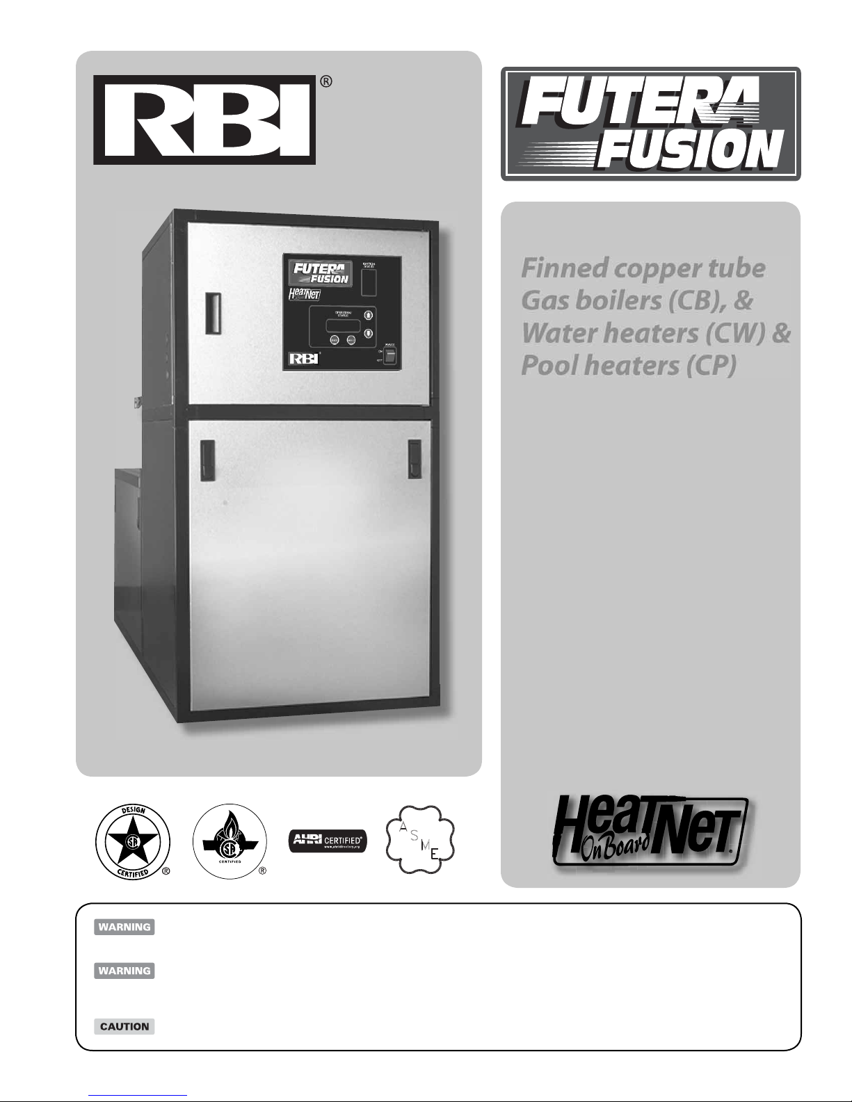
RBI CB500, CB750, CB1000, CB1250, CB1500 Installation And Operation Instructions Manual
...
FTF-I0M-HN-4
82-0312
Finned copper tube
Gas boilers (CB), &
Water heaters (CW) &
Pool heaters (CP)
Boiler manual
Installation and operation
instructions
Also read and follow:
HeatNet control manual
is manual is intended only for use by a quali ed heating installer/technician. Read and follow this manual, all supplements and related
instructional information provided with the boiler. Install, start and service the boiler only in the sequence and methods given in these
instructions. Failure to do so can result in severe personal injury, death or substantial property damage.
Do not use the boiler during construction. Construction dust and particulate, particularly drywall dust, will cause contamination
of the burner, resulting in possible severe personal injury, death or substantial property damage. e boiler can only be operated with
a dust-free air supply. Follow the instruction manual procedures to duct air to the boiler air intake. If the boiler has been contaminated
by operation with contaminated air, follow the instruction manual guidelines to clean, repair or replace the boiler if necessary.
A x these instructions near to the boiler. Instruct the building owner to retain the instructions for future use by a quali ed service
technician, and to follow all guidelines in the User’s Information Manual.
10/12 Copyright 2012 Mestek, Inc.
Fi
nned copper tube gas boilers & water heaters – Boiler Manua
l
F
F
If the information in this manual is not followed
exactly, a re or explosion may result causing property,
personal injury or loss of life.
Do not store or use gasoline or other ammable vapors
and liquids in the vicinity of this or any other applianc
WHAT TO DO IF YOU SMELL GAS:
• Do not try to light any appliance.
• Do not touch any electrical switch. Do not use any
phone in your building.
• Immediately call your gas supplier from a neighbor’s
phone. Follow the gas supplier’s instructions.
• If you cannot reach your gas supplier, call the re
department.
Installation and service must be performed by a quali ed
installer, service agency or the gas supplier.
Assurez-vous de bien suivre les instructions données
dans ce e notice pour réduire au minimum le risque
d’incendie ou d’explosion ou pour éviter tout dommoge
matériel, toute blessure ou la mort
Ne pas entreposer ni utiliser d’essence ou ni d’autres
vapeurs ou liquides in ammables à proximité de cet
appareil ou de tout autre appareil.
QUE FAIRE SI VOUS SENTEZ UNE ODEUR DE GAZ:
• Ne pas tenter d’allumer d’appareil.
• Ne touchez à aucun interrupteur; ne pas vous servir
des téléphones se trouvant dans le bâtiment.
BEFORE YOU START . . . . . . . . . . . . . . . . . . . . 2
RATINGS & CAPACITIES . . . . . . . . . . . . . . . . . . 3
BOILER/WATER HEATER LOCATION . . . . . . . . . . . . 3
COMBUSTION AIR & VENTILATION. . . . . . . . . . . . . 3
GENERAL VENTING GUIDELINES. . . . . . . . . . . . . . 5
OUTDOOR VENTING. . . . . . . . . . . . . . . . . . . . .10
GENERAL PIPING REQUIREMENTS . . . . . . . . . . . . 11
HEATING SYSTEM PIPING . . . . . . . . . . . . . . . . .12
DOMESTIC WATER SUPPLY PIPING . . . . . . . . . . . .16
GAS SUPPLY PIPING . . . . . . . . . . . . . . . . . . . .20
ELECTRICAL WIRING . . . . . . . . . . . . . . . . . . . . 21
GENERAL OPERATION . . . . . . . . . . . . . . . . . . . 22
OPERATING INSTRUCTIONS . . . . . . . . . . . . . . . . 24
SEQUENCE OF OPERATION . . . . . . . . . . . . . . . .25
CHECKING & ADJUSTMENTS. . . . . . . . . . . . . . . .26
HEATNET FIELD WIRING . . . . . . . . . . . . . . . . . .28
CONTROL DESCRIPTION . . . . . . . . . . . . . . . . . .28
DIAGNOSTIC . . . . . . . . . . . . . . . . . . . . . . . . . 31
MAINTENANCE . . . . . . . . . . . . . . . . . . . . . . .33
TROUBLE-SHOOTING . . . . . . . . . . . . . . . . . . . .33
REPAIR PARTS. . . . . . . . . . . . . . . . . . . . . . . . 34
START-UP SHEET . . . . . . . . . . . . . . . . . . . . . .40
WARRANTY . . . . . . . . . . . . . . . . . . . . . . . . . 43
• Appelez immédiatement votre fournisseur de gas depuis
un voisin. Suivez les intructions du fournisseur.
• Si vous ne purvez rejoindre le fournisseur, appelez le
service des incendies.
L’installation et l’entretien doivent être assurés par un
installateur ou un service d’entretien quali é ou par le
fournisseur de gaz.
Failure to properly vent this unit can cause excessive
amounts of carbon monoxide resulting in severe
personal injury or death!
DESIGNED AND TESTED ACCORDING TO A.S.M.E.
BOILER AND PRESSURE VESSEL CODE, SECTION
IV FOR A MAXIMUM ALLOWABLE WORKING PRESSURE OF 160 PSI, 1103 kPa WATER.
2
BEFORE YOU START
is manual covers the application, installation, operation and
maintenance of a Futera Series nned copper heating boiler/water
heater/pool heater.
To obtain the safe, dependable, e cient operation and long life
for which this heating boiler/water heater was designed, these
instructions must be read, understood and followed.
e Futera Series nned copper heating boiler/water heaters have
been design certi ed by CSA for use with natural and propane gas
under the latest revision of ANSI-Z21.10.3/CSA 4.3, Gas Water
Heaters, ANSI-Z21.13/CSA 4.9, Gas-Fired Low Pressure Steam
and Hot Water Boilers ANSI-Z21.56/CSA 4.7 Gas Fired Pool
Heaters and CAN1-3.1, Industrial and Commercial Gas Fired
Packaged Boilers. Each unit has been constructed and hydrostatically
tested for a maximum working pressure of 160 psi, 1103 kPa in
accordance with Section IV of the A.S.M.E. Boiler and Pressure
Vessel Code.
All aspects of the boiler/water heater installation must conform to
the requirements of the authority having jurisdiction, or, in the
absence of such requirements, to the National Fuel Gas Code, ANSI
Z223.1/NFPA 54-latest revision. Where required by the authority
having jurisdiction, the installation must conform to the Standard
for Controls and Safety Devices for Automatically Fired Boilers,
ANSI/ASME CSD-1.
Finned copper tube gas boilers & water heaters – Boiler Manual
Fi
nned copper tube gas boilers & water heaters – Boiler Manua
l
F
In Canada, the installation must be in accordance with the
requirements of CSA B149.1 or .2, Installation Code for Gas
Burning Appliances and Equipment.
If installed in the Commonwealth of Massachuse s, you MUST
FOLLOW the additional instructions contained in RBI’s instruction
sheet MACODE-3. Which is located in the back of this manual.
e owner should maintain a record of all service work performed
with the date and a description of the work done. Include the name
of the service organization for future reference.
Direct all questions to your RBI distributor or contact the RBI
Customer Service Department at: 260 North Elm Street, West eld,
MA 01085 for US or 7555 Tranmere Drive, Mississauga ONT L5S
1L4 for Canada. Always include the model and serial numbers from
the rating plate of the boiler/water heater in question.
RATINGS & CAPACITIES
Before undertaking the installation of the Futera Series boiler/water
heater check the rating plate to ensure that the unit has been sized
properly for the job. e “Net AHRI Ratings” specify the equivalent
amount of direct copper radiation that the unit can supply under
normal conditions. Also ensure that the unit has been set up for
the type of gas available at the installation site. Other important
considerations are the availability of an adequate electrical supply,
fresh air for combustion and a suitable chimney or vent system.
BOILER/WATER HEATER LOCATION
1. is boiler/water heater is suitable for indoor and outdoor
installations. Locate the boiler/water heater in an area that
provides good access to the unit. Servicing may require
the removal of jacket panels. Allow the minimum clearances
between adjacent construction and the boiler/water heater as
listed in Table 1.
Service clearances are not mandatory, but are recom-
mended to ensure ease of service should it be required.
Table 1
Clearance to
Combustibles
To p 6 153 30 762
Back 6 153 24 610
Left Side 6 153 24 610
Right Side 6 153 24 610
Front 6 153 30 762
in mm in mm
Service
Clearance
2. An optimum site will be level, central to the piping system,
close to a chimney or outside wall and have adequate fresh air
for combustion. Ensure that the boiler/water heater is level from
front to back and from side to side. Use metal shims to level
the boiler/water heater. Electrical and electronic components
must also be protected from exposure to water during operation
and maintenance. DO NOT install this boiler/water heater in
a location that would subject any of the gas ignition components
to direct contact with water or excessive moisture during
operation or servicing.
3. Ensure that the oor is structurally sound and will support
the weight of the boiler/water heater.
e Futera may be installed directly on combustible
ooring, but never on carpeting.
4. Locate the boiler/water heater in an area that will prevent
water damage to adjacent construction should a leak occur or
during routine maintenance. If such a location doesn’t exist,
a suitable drain pan that’s adequately drained must be installed
under the unit.
5. DO NOT place this boiler/water heater in a location that
would restrict the introduction of combustion air into the unit
or subject it to a negative pressure, see “GENE L VENTING
GUIDELINES”.
6. NEVER place this boiler/water heater in a location that
would subject it to temperatures at or near freezing, see the
“FREEZE PROTECTION” section on page 11.
Never store combustible materials, gasoline or any
product containing ammable vapors or liquids in
the vicinity of the boiler/water heater. Failure to
comply with this warning can result in an explosion
or re causing extensive property damage, severe
personal injury or death!
COMBUSTION AIR & VENTILATION
is boiler/water heater must be supplied with
combustion air in accordance with Section 5.3,
Air for Combustion & Ventilation, of the latest
revision of the National Fuel Gas Code, ANSI
Z223.1/NFPA 54 and all applicable local building
codes. Canadian installations must comply with
CAN/CGA B149.1 or .2 Installation Code for Gas
Burning Appliances and Equipment, or applicable
provisions of the local building codes. Failure to
provide adequate combustion air for this boiler/
water heater can result in excessive levels of carbon
monoxide which can result in severe personal injury
or death!
To operate properly and safely this boiler/water heater requires
a continuous supply of air for combustion. NEVER store objects
on or around the boiler/water heater!
3
Fi
nned copper tube gas boilers & water heaters – Boiler Manua
l
F
F
Combustion air contaminated with uorocarbons
or other halogenated compounds such as cleaning
solvents and refrigerants will result in the formation
of acids in the combustion chamber. ese acids will
cause premature failure of the boiler/water heater
voiding the warranty!
If the boiler/water heater is operated while the building
is under construction it MUST be protected from
wood, concrete, sheet rock and other types of dust.
Failure to properly protect the unit from construction
dust will damage the unit voiding the warranty!
Buildings will require the installation of a fresh air duct or other
means of providing make-up air if the intake air option isn’t used.
Any building utilizing other gas burning appliances, a replace, wood
stove or any type of exhaust fan must be checked for adequate
combustion air when all of these devices are in operation at one
time. Sizing of an outside air duct must be done to meet the
requirements of all such devices.
Never operate the Futera in an environment subjected
to a negative pressure unless it is Direct Vented. Failure
to comply with this warning can result in excessive
levels of carbon monoxide causing severe personal
injury or death!
Where directly communicating with the outdoors or communi-
cating with the outdoors through vertical ducts, each opening shall
have a minimum free area of 1 in
2
/4000 Btu/hr, 550 mm2/kW
of the total input rating of all of the equipment in the enclosure.
Where communicating with the outdoors through horizontal
ducts, each opening shall have a minimum free area of 1 in
2
2000 Btu/hr, 1100 mm2/kW of the total input rating of all of
the equipment in the enclosure.
When ducts are used, they must have the same cross-sectional area
as the free area of the opening to which they connect.
When calculating the free area necessary to meet the make-up
air requirements of the enclosure, consideration must be given
to the blockage e ects of louvers, grills and screens. Screens must
have a minimum mesh size of 1/4 in, 6.4 mm. If the free area
through a louver or grill is not known, ducts should be sized per
Table 2.
Canadian installations must comply with CSA B149.1 when
air supply is provided by natural air ow from the outdoors for
natural dra , partial fan-assisted, fan-assisted, or power dra -
assisted burners, there shall be a permanent air supply opening(s)
having a cross-sectional area of not less than 1 in
2
per 7,000
Btuh (310 mm2 per kW) up to and including 1 million Btuh,
plus 1 in2 per 14,000 Btuh (155 mm2 per kW) in excess of
1 million Btuh.
/
All Air From Inside The Building
If the Futera is to be located in a con ned space, the minimum
clearances listed in Table 1 must be maintained between it and any
combustible construction. When installed in a con ned space
without the intake air option, Figures 5 and 6, two permanent
openings communicating with an additional room(s) are required.
e combined volume of these spaces must have su cient volume
to meet the criteria for an uncon ned space. e total air
requirements of all gas utilization equipment, replaces, wood stoves
or any type of exhaust fan must be considered when making this
determination. Each opening must have a minimum free area of
1 in2/1000 Btu/hr, 2200 mm2/kW based on the total input rating
of ALL gas utilization equipment in the con ned area. Each opening
must be no less than 100 in2, 64,516 mm2 in size. e upper
opening must be within 12 in, 305 mm of, but not less than 3 in,
76 mm from, the top of the enclosure. e bo om opening must
be within 12 in, 305 mm of, but not less than 3 in, 76 mm from,
the bo om of the enclosure.
All Air From Outside The Building
When installed in a con ned space without utilizing the intake
air option two permanent openings communicating directly with,
or by ducts to, the outdoors or spaces that freely communicate
with the outdoors must be present. e upper opening must be
within 12 in, 305 mm of, but not less than 3 in, 76 mm from, the
top of the enclosure. e bo om opening must be within 12 in,
305 mm of, but not less than 3 in, 76 mm from, the bo om of
the enclosure.
Table 2 Make-up Air Louver Sizing
Required Cross Sectional Area
2
75% Free Area
Metal Louvers
2
in
cm
1/4 in 6.4 mm
Input
(MBH)
500 125 806 167 1077 500 3226
750 187 1206 250 1613 750 4839
1000 250 1613 333 2148 1000 6452
1250 313 2019 416 2684 1250 8065
1500 375 2419 500 3226 1500 9677
1750 437 2819 583 3761 1750 11,290
1999 500 3226 667 4303 2000 12,900
Wire Screen
2
cm
in
2
25% Free Area
Wooden Louvers
in
2
cm
2
Intake Air Option – General Guidelines
is con guration provides combustion air directly to the boiler/
water heater’s air intake adapter using a dedicated pipe when using
the direct vent option. Combustion air can be drawn in horizontally
through the same outside wall which terminates the exhaust gases
or vertically through the roof, see Figures 1, 2, 3 & 4.
Common intake air systems may be used provided
the common duct is sized properly. An intake
combustion air damper should be installed if the
common vent option is used in the intake air pipe of
each heater. Improper installation can result in excessive
levels of carbon monoxide which can cause severe
personal injury or death!
4
Finned copper tube gas boilers & water heaters – Boiler Manual
Fi
nned copper tube gas boilers & water heaters – Boiler Manua
l
F
Single wall galvanized smoke pipe, single wall aluminum pipe,
exible aluminum pipe, PVC or CPVC pipe can be used for the
intake air pipe. It must be sized per Table 3.
Table 3 Intake Air Pipe Sizing (Up to 60 ft)
Model
Size
500 8 203
750 8 203
1000 8 203
1250 10 254
1500 10 254
1750 12 305
2000 12 305
Note: Max horizontal/vertical intake pipe 60 ft equivalent.
in mm
All joints in metal intake air systems must be secured using corro-
sion resistant fasteners and sealed using a suitable Silicone caulk.
If PVC or CPVC is used, the joints must be cleaned with a suitable
solvent and connected using a solvent based PVC cement. e
combustion air system MUST be supported by the building
structure not the boiler/water heater.
A combustion air damper interlocked with the unit
should be installed in the intake air pipe when the
in ltration of subfreezing air could occur, otherwise
the unit could freeze up voiding the warranty!
All vent systems must be fully supported by the building structure
and not by the boiler/water heater. Appropriate thimbles and restops must be used where required.
Common vent systems must be properly engineered
and sized, please contact the factory.
A UL listed stainless steel vent system must be used
unless this unit is ed with an RBI supplied non
metallic vent kit. Failure to comply with this warning
can cause excessive levels of carbon monoxide resulting
in severe illness and death!!
For instructions utilizing the non-metallic vent option,
see Addendum (FTF-PVCVO) for PVC and (FTF-
PPVO) for Polypropylene.
VENT SYSTEM OPTIONS
e ue products in the vent system may be cooled below their
dew point and form condensate in the ue. e materials used for
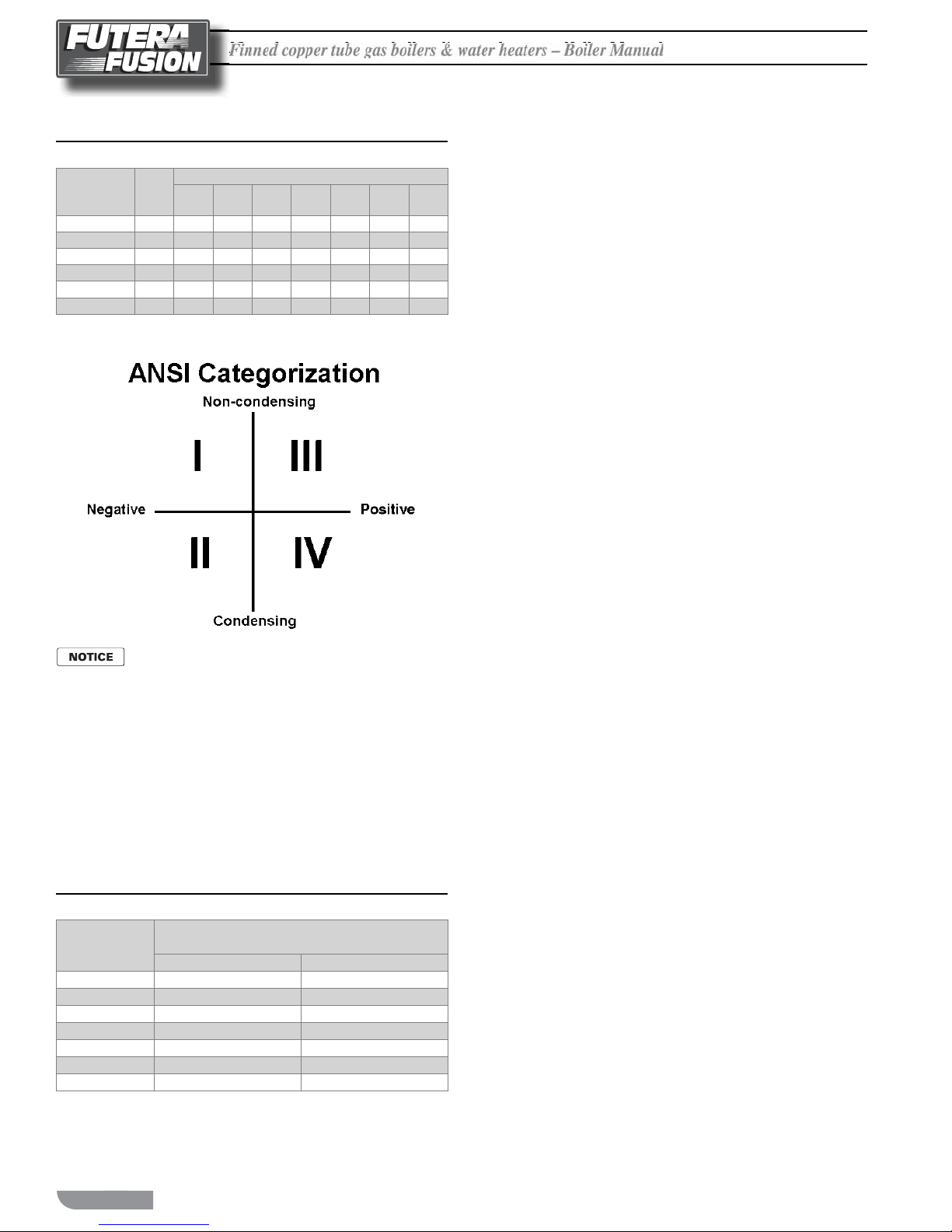
a Category IV vent must be resistant to any corrosive damage
from ue gas condensate. e ue from a Category IV vent system
must have a condensate drain with provisions to properly collect
and dispose of any condensate that may occur in the venting system.
e Futera Fusion may be vented the following ways:
Intake Air Option – Vertical Guidelines
e maximum equivalent length for the vertical intake air pipe is
60 , 18.3 m. Each 90° elbow and the intake air terminal are equal
to 10 linear , 3.0 m of pipe, see Table 3.
An approved, nonrestrictive intake air terminal must be used. e
intake air terminal must terminate as shown in Figure 3. e
penetration point in the roof must be properly ashed and sealed.
Intake Air Option – Horizontal Guidelines
e maximum equivalent length for the horizontal intake air pipe
is 60 , 18.3 m. Each 90° elbow and the intake air terminal
are equal to 10 linear , 3.0 m of pipe. If horizontal runs exceed
5 , 1.5 m they must be supported at 3 , 0.9 m intervals with
overhead hangers. e certi ed intake air terminal from RBI must
be used, see Figures 1, 2 and 4.
GENERAL VENTING GUIDELINES
e vent installation must be in accordance with Part
7, Venting of Equipment, of the National Fuel Gas
Code, ANSI Z223.1/NFPA 54-latest revision or applicable provisions of the local building codes. Canadian
installations must comply with CAN/CGA B149.1
or .2 Installation Code. Improper venting can result
in excessive levels of carbon monoxide which can
result in severe personal injury or death!
1) Direct Vent, Positive Pressure, Category IV uses a vent
system certi ed to UL 1738 for installations in the United
States, ULC S636 for installations in Canada. Combustion air
is piped from the outdoors to the blower inlet.
2) Side Wall Vent, Positive Pressure, Category IV uses
a vent system certi ed to UL 1738 for installations in the
United States, ULC S636 for installations in Canada. Combustion air is obtained from the space in which the unit is installed.
3) Vertical Vent, Positive Pressure, Category IV uses a
vent system certi ed to UL 1738 for installations in the United
States, ULC S636 for installations in Canada. Combustion air
is obtained from the outdoors or the space in which the unit
is installed.
4) Vertical Vent, Negative Pressure, Category II (common
venting) requires negative pressure in vent (natural dra ).
Requires a metal chimney system approved for Category II
venting. is method is required if common venting multiple
Fusion boilers.
All venting and combustion air material supplied by
installer. All venting materials must be approved for
the application. Consult the vent manufacturer’s
product literature.
e maximum equivalent length for the ue outlet vent
system for Category IV conditions is 60 , 18.3 m.
Use Table 4 for the equivalent lengths per ing. Table
4 - “Category IV Equivalent Length per Fi ing” chart
is meant as a guideline for preliminary sizing. If vent
length approaches 75% of maximum length listed an
engineered vent system calculation must be performed,
consult factory.
5
Fi
nned copper tube gas boilers & water heaters – Boiler Manua
l
F
F
Table 4 Category IV Equivalent Length Per Fitting
Model/Outlet
Diameter
Standard Tee 1.25 25 ft 25 ft 30 ft 30 ft 35 ft 40 ft 40 ft
Boot Tee 0.65 15 ft 15 ft 15 ft 15 ft 15 ft 20 ft 20 ft
Cap - Low Res (UL) 0.50 10 ft 10 ft 10 ft 10 ft 10 ft 15 ft 15 ft
45° w/Bird Screen 0.40 10 ft 10 ft 10 ft 10 ft 10 ft 10 ft 10 ft
Elbow - 90° 0.38 10 ft 10 ft 10 ft 10 ft 10 ft 15 ft 15 ft
Elbow - 45° 0.15 5 ft 5 ft 5 ft 5 ft 5 ft 5 ft 40 ft
*Equivalent lengths based on listed K-factors and (5x) pipe diameters straight length between ttings.
*K
CB5007"CB7507"CB10007"CB12508"CB15008"CB1750
Must consult factory when venting single or multiple unit(s)
over 60 equivalent feet. Mechanical system may be required.
Equivalent Feet of Straight Pipe
10"
CB2000
10"
Horizontal Direct Vent Systems
Figures 1 & 2
e vent materials used in horizontal vent systems must be certi ed
to UL 1738 for installations in the United States, ULC S636 for
installations in Canada. e certi ed vent terminal from RBI must
also be used.
If any part of a single wall metal vent system passes through an
unheated space, it must be insulated with insulation rated for 400°F,
204°C. Structural penetrations must be made using approved re-
stops. For best results, horizontal vent systems should be as short
and straight as possible.
e vent system must be both gas tight and watertight. All seams
and joints in metal pipes must be joined and sealed in accordance
with the vent system manufacturer’s instructions.
When horizontal vent runs exceed 5 , 1.5 m they must be supported
at 3 , 0.9 m intervals with overhead hangers. e vent system must
be pitched down, toward the vent terminal, 1/4 in/ , 20 mm/m. If
any part of a single wall metal vent system passes through an unheated
space it must be insulated with insulation rated for 400°F, 204°C.
Horizontal vent systems shall terminate at least 4 , 1.2 m below,
4 , 1.2 m horizontally from or 1 , 0.30 m above any door, window
or gravity air inlet into any building. It must not terminate less than
4 , 1.2 m horizontally from, and in no case above or below, unless
a 4 , 1.2 m horizontal distance is maintained, from electric meters,
gas meters, regulators and relief equipment and not less than 7 ,
2.1 m above adjacent public walkway. e bo om of the vent
terminal(s) shall be located at least 5 , 1.5 m above the air intake
terminal(s) unless there is a minimum 5 , 1.5 m horizontal
separation between them. Avoid terminal locations likely to be
a ected by winds, snowdri s, people and pets. Protect building
materials and vegetation from degradation caused by the ue gases.
DIRECT VENT, POSITIVE PRESSURE,
CATEGORY IV
In this con guration the boiler/water heater blower is used to push
the ue products to the outdoors while drawing combustion air
from the outdoors. e Intake Air Option instructions under the
“COMBUSTION AIR & VENTILATION” section must be
followed! e vent system must be sized per Table 5.
Table 5 Category IV
Model
Size
500 7 178
750 7 178
1000 7 178
1250 8 203
1500 8 203
1750 10 254
2000 10 254
Pipe Diameter (Min.)
(Up to 60 ft)
in mm
6
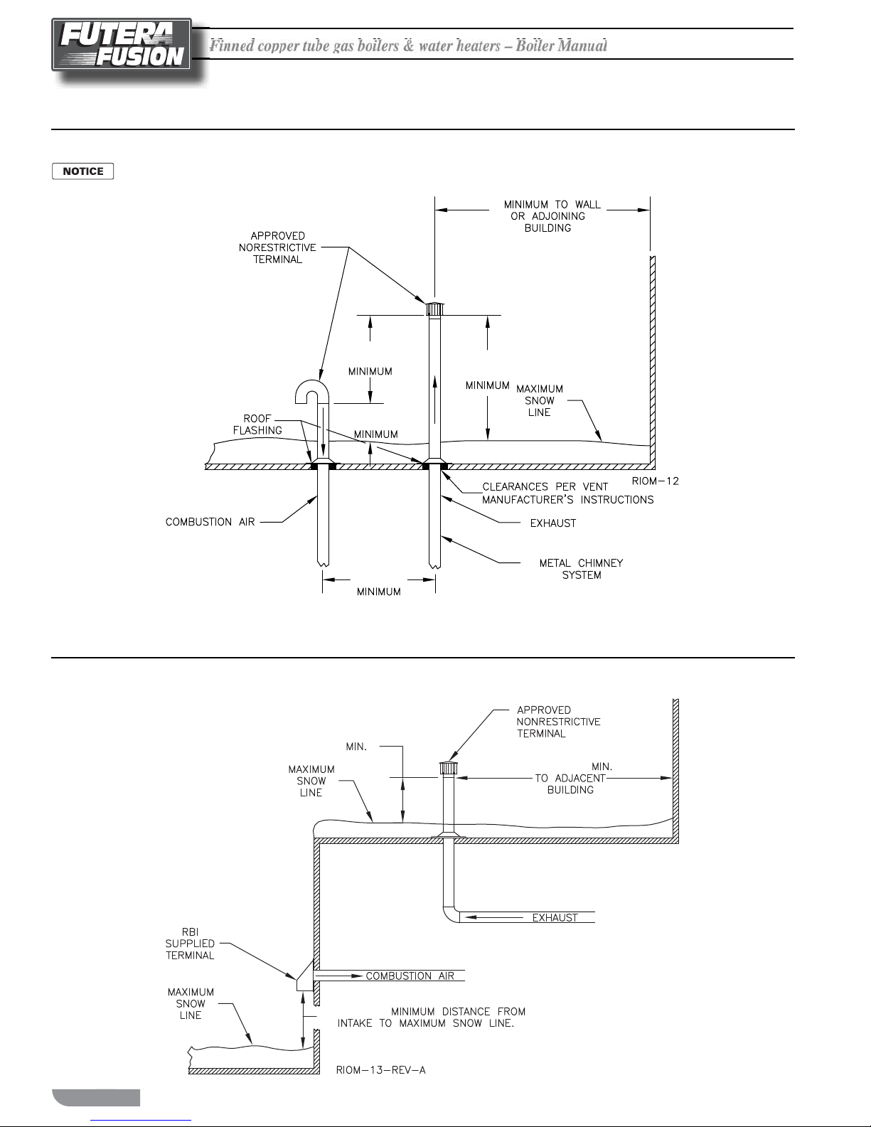
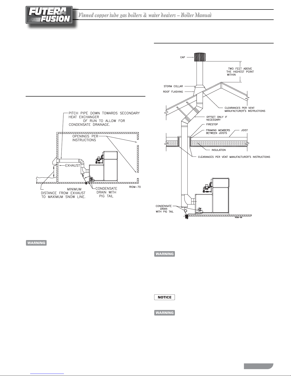
Vertical Direct Vent Systems – Figure 3
If any part of a single wall metal vent system passes through an unheated
space, it must be insulated with insulation rated for 400°F, 204°C.
Structural penetrations must be made using approved re-stops.
An approved, nonrestrictive vent terminal must be used. e top
of a vertical vent system must extend at least 51/2 , 1.7 m above
the roof surface and maximum snow line that it passes through,
4 , 1.2 m above the intake air terminal, see Figure 3.
In addition the vent system must conform to the dimensions shown
in Figure 3. e penetration point in the roof must be properly
ashed and sealed.
e vent system must be gas tight. All seams and joints in metal
pipes must be joined and sealed in accordance with the vent system
manufacturer’s instructions.
Combination Direct Vent Systems – Figure 4
e boiler/water heater can be vented vertically with the intake
air piped horizontally through an outside wall. Follow the instructions in the Intake Air Option – Horizontal Guidelines on page
5. Also follow the general instructions in the “COMBUSTION
AIR & VENTILATION” and “GENE L VENTING GUIDE
LINES” sections.
Finned copper tube gas boilers & water heaters – Boiler Manual
Fi
nned copper tube gas boilers & water heaters – Boiler Manua
l
F
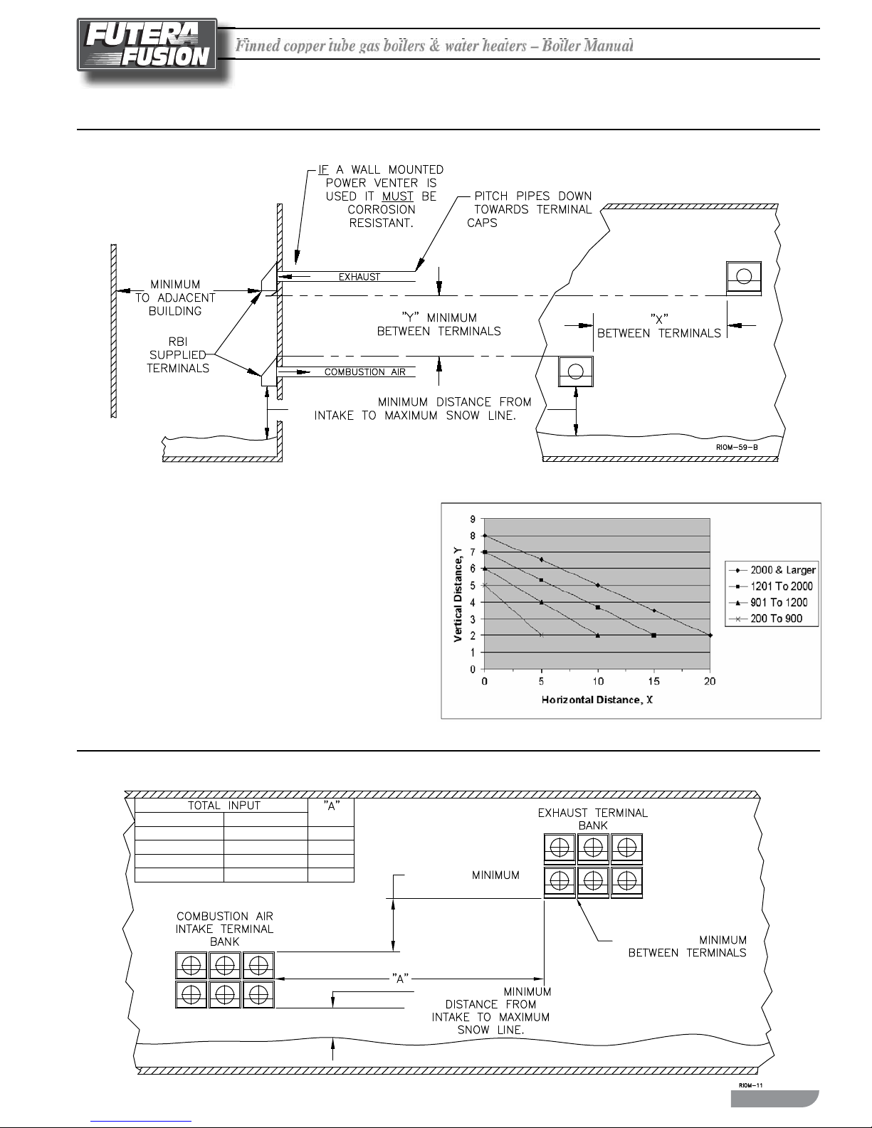
Figure 1 Horizontal Air Intake and Venting for a Single Direct Vent System
16 FT 4.9 m
1.5 FT 0.5 m
1/4 IN. PER FOOT
20 mm/m
When running horizontal combustion air and venting for
single or multiple units, exhaust and combustion air
terminals must be installed on the same plane (outside wall)
in order to prevent pressure di erences due to prevailing
winds. In cold climates, double-wall or insulated inlet pipe
recommended to prevent condensation.
Figure 2 Horizontal Air Intake and Venting for Multiple Direct Vent Systems
MBH
500 TO 1000
1001 TO 2000
2001 TO 4000
4001 & LARGER
kW
146 TO 293
293 TO 586
586 TO 1172
1172 & LARGER
FT m
5 1.5
10 3.1
15 4.6
20 6.1
5 FT 1.5 m
1.5 FT 0.5 m
1000 BTU’S
2 IN. 5.0 cm
7
Fi
nned copper tube gas boilers & water heaters – Boiler Manua
l
F
F
10 FT 3.1 m
4 FT
1.2 m
5 FT
1.5 m
1.5 FT
0.5 m
5 1/2 FT
1.7 m
Figure 3 Vertical Air Intake and Venting for a Direct Vent System
Locate exhaust terminal downwind to reduce ue gas recirculation.
Figure 4 Horizontal Air Intake and Venting for Multiple Direct Vent Systems
3 FT. 1 m
1.5 FT. .5 m
10 FT. 3.1 m
8
Finned copper tube gas boilers & water heaters – Boiler Manual
Fi
nned copper tube gas boilers & water heaters – Boiler Manua
l
F
SIDE WALL VENT, POSITIVE PRESSURE,
CATEGORY IV – Figure 5
In this con guration the boiler/water heater blower is used to push the ue
products horizontally to the outdoors, see Figure 5. e air for combustion
is taken from the space in which the unit is installed. e applicable instructions
under the “COMBUSTION AIR & VENTILATION” section must be
followed! e vent guidelines under the Horizontal Direct Vent Systems
section must also be followed.
Figure 5 Side Wall Venting
1/4 IN. PER F00T
20 mm/m
Figure 6 Vertical Venting with a Metal Chimney System
10 FT. 3.1 m
1.5 FT 0.5 m
VERTICAL VENT, POSITIVE PRESSURE,
CATEGORY IV – Figure 6
(Vent pipe equivalent length up to 60 , 18.3 m maximum)
Masonry chimneys, when used, must be lined with a
metal liner certi ed for Category IV venting.
A through inspection of the masonry chimney must be performed
to ensure that the chimney is clean, properly constructed lined, and
sized. Exterior masonry chimneys should not be used unless
properly lined to prevent condensation and dra problems.
VERTICAL CHIMNEY VENTING NEGATIVE
PRESSURE — CATEGORY II
Category II venting is required for multiple Fusion
boilers connected to a common vent. Common vent
systems cannot be pressurized.
e Fusion is listed as a CategoryII appliance when vented vertically
into a listed metal chimney system. e chimney must provide a
negative pressure not greater than 0.10inch, 2.5 mm WC at the
boiler/water heater ue collar with the unit running.
When using a listed metal chimney system the chimney
system manufacturer’s instructions must be followed.
Masonry chimneys, when used, must be lined with a
metal liner certi ed for Category IV venting.
(Common Venting)
9
Fi
nned copper tube gas boilers & water heaters – Boiler Manua
l
F
F
g
e vent piping must be large enough to safely vent the
combined output of all of the appliances connected
to the system.
If an appliance using any type of a mechanical dra
system operating under positive pressure is connected
to a chimney ue, never connect any other appliances
to this ue. Doing so can result in excessive levels of
carbon monoxide which can cause severe personal
injury or death!
CATEGORY II CHIMNEY INSPECTION
& SIZING
Masonry chimneys, when used, must be lined with a
metal liner certi ed for Category IV venting.
A thorough inspection of the masonry chimney must be performed
to ensure that the chimney is clean, properly constructed, lined
and sized. Exterior masonry chimneys should not be used unless
properly lined to prevent condensation and dra problems.
Table6 lists the minimum riser sizes required for the Fusion boiler/
water heater.
Vent Connections
Locate the boiler/water heater as close to the chimney as possible.
Use the shortest, straightest vent connector possible for the instal-
lation. If horizontal runs exceed 5 , 1.5 m they must be supported
at 3 , 0.9 m intervals with overhead hangers.
e vent connector should be sloped up toward the chimney at a
minimum rate of 1/4 in/ , 21 mm/m. On masonry chimneys the
connector must terminate ush with the inside of the chimney ue.
Always provide a minimum clearance of 6 in, 152 mm between
single wall vent pipe and any combustible materials.
Failure to maintain minimum clearances between vent
connectors and any combustible material can result
in a re causing extensive property damage, severe
personal injury or death!
Exit cones are favorable when used to increase
the velocity of the ue gas exiting the stack and,
may also help, in cold climates, to reduce ice buildup. Exit cone terminations must be supplied by
others, installed per manufacturer’s instructions,
and meet local and federal code.
eneric exit cone
Table 6 Equivalent Breeching & Chimney Size, Negative Pressure
Model
Size
500 7 178
750 7 178
1000 8 203
1250 8 203
1500 8 203
1750 10 254
2000 10 254
Note: These sizes are based on a 20 ft, 6.1 m chimney height.
Pipe Diameter
in mm
CATEGORY II VENT CONNECTIONS
Locate the boiler/water heater as close to the chimney as possible.
Use the shortest, straightest vent connector possi ble for the installation.
If horizontal runs exceed 5 , 1.5 m they must be supported at 3 ,
0.9 m intervals with overhead hangers.
e boiler vent connectors should be sloped up toward the breeching
at a minimum rate of 1/4 in per , 21mm per m.
Always provide a minimum clearance of 6 in, 152 mm
single wall vent pipe and any combustible materials.
Failure to maintain minimum clearances between
vent connectors and any combustible material can
result in a re causing extensive property damage,
severe personal injury or death!
between
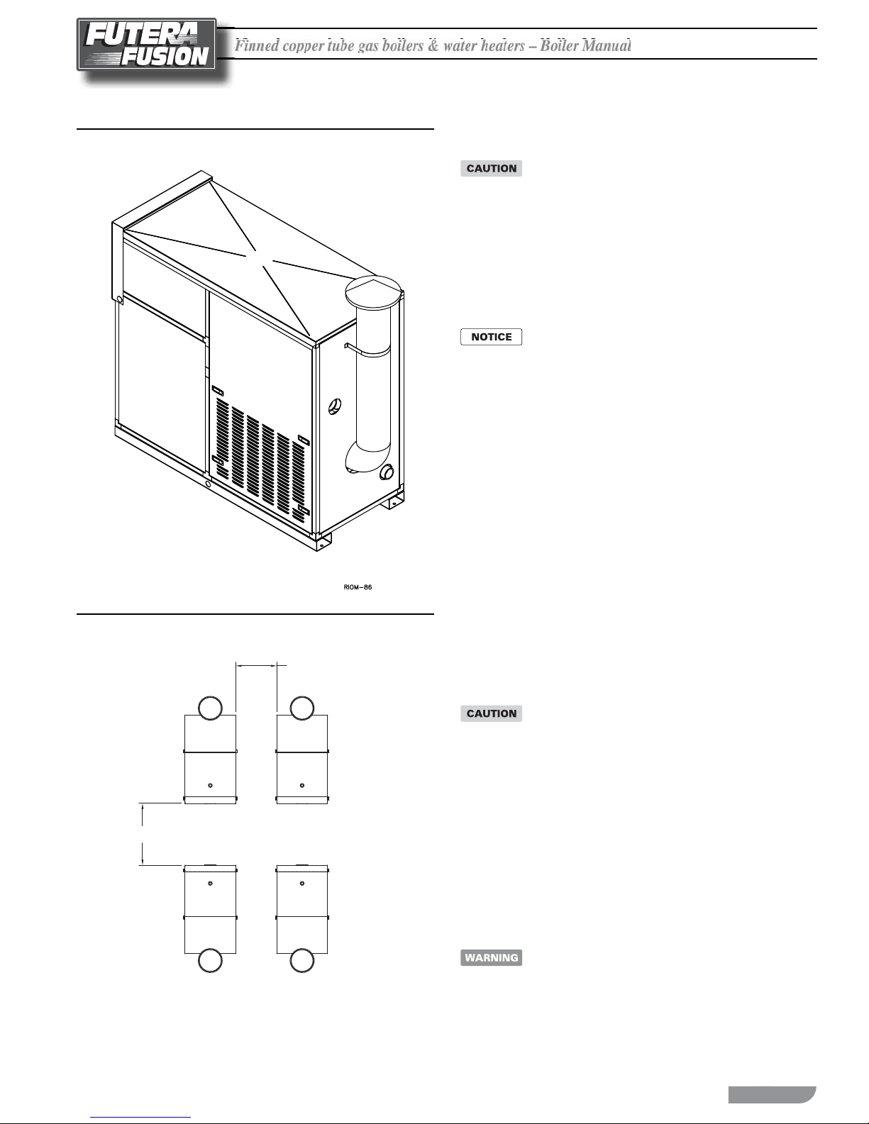
OUTDOOR VENTING
When installed outdoors the Futera Fusion must be ed with the
factory supplied outdoor hood, air intake adapter with lter and
exhaust terminal, see Figure 7. Multiple units must be spaced per
Figure 8.
e boiler/heater must be at least 2 , .62 m from any door, window
or gravity air inlet into any building and at least 3 , 1 m from any
overhang unless local codes dictate di erently.
Avoid locations where wind de ection o of adjacent walls,
buildings or shrubbery might cause a downdra . e unit(s) should
be located at least 3 , 1 m from structures. Outdoor installations
are not recommended in areas where the danger of snow blockage
exists.
Do not place the boiler/water heater in a location that
would subject it to runo from adjacent buildings or
damage may occur voiding the warranty!
Outdoor Installations
e Futera Boiler is certi ed for outside installations
in temperate climates only.
1. e condensate traps located under the secondary heat exchanger
and the vent pipe must be wrapped with heat tape to ensure the
traps never drop below 32°F.
2. e vent pipe must be insulated to prevent freezing of condensate
in the pipe.
3. e boiler and system must be lled with an ethylene glycol/
water antifreeze mixture not to exceed 50% glycol by volume.
4. All water piping exposed to low temperatures must be insulated.
10
Finned copper tube gas boilers & water heaters – Boiler Manual
Fi
nned copper tube gas boilers & water heaters – Boiler Manua
l
F
A
Figure 7 Outdoor Venting
Figure 8 Multiple Outdoor Units
2 FT
(0.62 M)
GENERAL PIPING REQUIREMENTS
Improper piping of this boiler/water heater will void
the manufacturer’s warranty and can cause boiler
failure resulting in ooding and extensive property
damage! Excessive water hardness causing scaling
in the copper heat exchanger tubes is NOT covered
under the manufacturer’s warranty, see Table 8.
Excessive pi ing and erosion of the internal surface of
the copper heat exchanger tubes is NOT covered
under the manufacturer’s warranty if the result of high
water ow rates.
Shut o valves and unions should be installed at the
inlet and outlet connections of the boiler/hot water
heater to provide for isolation of the unit should
servicing be necessary.
Freeze Protection
Installations in areas where the danger of freezing exists are not
recommended unless proper freeze protection is provided. e
following precautions MUST be observed:
A continuous ow of water through the unit MUST be maintained!
1.
e pump responsible for ow through the boiler/water heater
must run continuously!
2. An ethylene glycol/water mixture suitable for the minimum
temperature that the unit will be exposed to must be used.
e pump must be capable of producing a minimum of 15%
more ow and overcoming a 20% increase in head loss.
Domestic water systems must be isolated from the water heater
by the use of a heat exchanger or other approved method.
3. If the unit must be shut o for any reason the electric, gas and
water supplies MUST be shut o and the unit and its pump
completely drained.
3 FT
(1 M)
RIOM-60 REV.
Improper outdoor installation of this unit can cause
boiler failure voiding the manufacturer’s warranty!
Condensate Piping
e condensate trap provided with the boiler must be a ached to
the bo om pan and piped to a suitable oor drain or condensate
pump. If a condensate neutralization device is installed, it must be
positioned prior to boiler room drain. Condensate ll trap must
be maintained with uid.
Relief Valve
Pipe the discharge of the pressure relief valve as shown in Figure 9.
Never install any type of valve between the boiler/
water heater and the relief valve or an explosion causing
extensive property damage, severe personal injury or
death may occur!
11
Fi
nned copper tube gas boilers & water heaters – Boiler Manua
l
F
F
Flow Switch
e ow switch supplied with the boiler/water heater must be
wired to the terminal strip in the control panel to prevent the boiler
from ring unless there’s adequate water ow through the unit. e
ow switch must be installed in the supply piping adjacent to the
boiler outlet connection.
Failure to properly install the ow switch may result
in damage to the boiler/water heater heat exchanger
voiding the warranty!
HEATING SYSTEM PIPING
General Piping Requirements
All heating system piping must be installed by a quali ed technician
in accordance with the latest revision of the ANSI/ASME Boiler and
Pressure Vessel Code, Section IV, and ANSI/ASME CSD-1,
Standard for Controls and Safety Devices for Automatically Fired
Boilers. All applicable local codes and ordinances must also be
followed. A minimum clearance of 1 in, 25 mm must be maintained
between heating system pipes and all combustible construction.
All heating system piping must be supported by suitable hangers
not the boiler. e thermal expansion of the system must be
considered when supporting the system. A minimum system
pressure of 12 psig, 82.7 kPa must be maintained.
Bleed Air From Boiler
Open the water heater piping bleed valves one at a time, to purge
the air trapped in the primary and secondary heat exchangers. Refer
to piping drawings (Figures 9, 10 & 11) for bleed locations.
Heating Boiler Piping Connections
e supply and return connections should be sized to suit the system,
see Table 7.
Table 7 Supply & Return Pipe Sizing
Model Size Supply Size Return Size
500 thru 1000 2” NPT 2” NPT
1250 thru 2000 2 1/2” NPT 2 1/2” NPT
Pump Requirements
is low mass boiler requires a continuous minimum water ow
for proper operation. e boiler pump is sized to overcome the
head loss of the boiler and the near piping in order to achieve the
required temperature rise. e temperature rise across the boiler
must never exceed 35°F, 19.4°C. e adjustable pump delay turns
the pump on each time the burner res and runs the pump for 20
to 600 seconds a er the call for heat is satis ed.
e maximum allowable primary heat exchanger
temperature rise is 35°F, 19.4°C.
e maximum allowable ow rate through a Futera Fusion boiler
is 97 GPM, 6.1 L/s on 500 through 1000 models and 136 GPM,
8.6 L/s for 1250 through 2000 models. e Cupro-Nickel heat
exchanger allows for 108 GPM, 6.8 L/s on 500 through 1000 models
and 151 GPM, 9.5 L/s on 1250 through 2000 models.
Factory Supplied - On Board - Circulating Pump
e factory installed - on board - pump is sized to work the total
boiler head loss plus an additional (30 ) of pipe and (6 elbows)
- (min pipe diameter of inlet/outlet boiler water connections - see
Table 7). Please consult factory for systems outside these parameters.
Low Water Cuto
If a boiler is installed above any radiation elements it must be ed
with a low water cuto device.
Refer to the wiring diagram supplied with the boiler/water heater
for proper wiring connections.
Expansion Tank & Air Separator
An expansion tank or other means to control thermal expansion
must be installed in the heating system. An expansion tank must
be installed close to the boiler on the suction side of the pump. An
air scoop and automatic air vent must also be installed to eliminate
air trapped in the system.
Primary/Secondary Piping
Figure 10 shows a typical primar y/secondary piping system. Boilers
connected to heating systems using zone valves, zone pumps, or
systems that have excessive ow rates must be isolated from these
systems to protect the boiler.
Multiple Boiler Systems
Systems using multiple boilers can also be installed using a primary/
secondary manifold system, Figure 11.
Piping For Use With Cooling Units
e boiler, when used in connection with a refrigeration system,
must be installed so the chilled medium is piped in parallel with
the boiler. Appropriate valves must be used to prevent the chilled
water from entering the boiler.
When a boiler is connected to a heating coil that may be exposed
to refrigerated air from an air handling device, the piping system
must be equipped with ow-control valves or some other automatic
means of preventing gravity circulation of the boiler water during
the cooling cycle.
12
Finned copper tube gas boilers & water heaters – Boiler Manual
Fi
nned copper tube gas boilers & water heaters – Boiler Manua
l
F
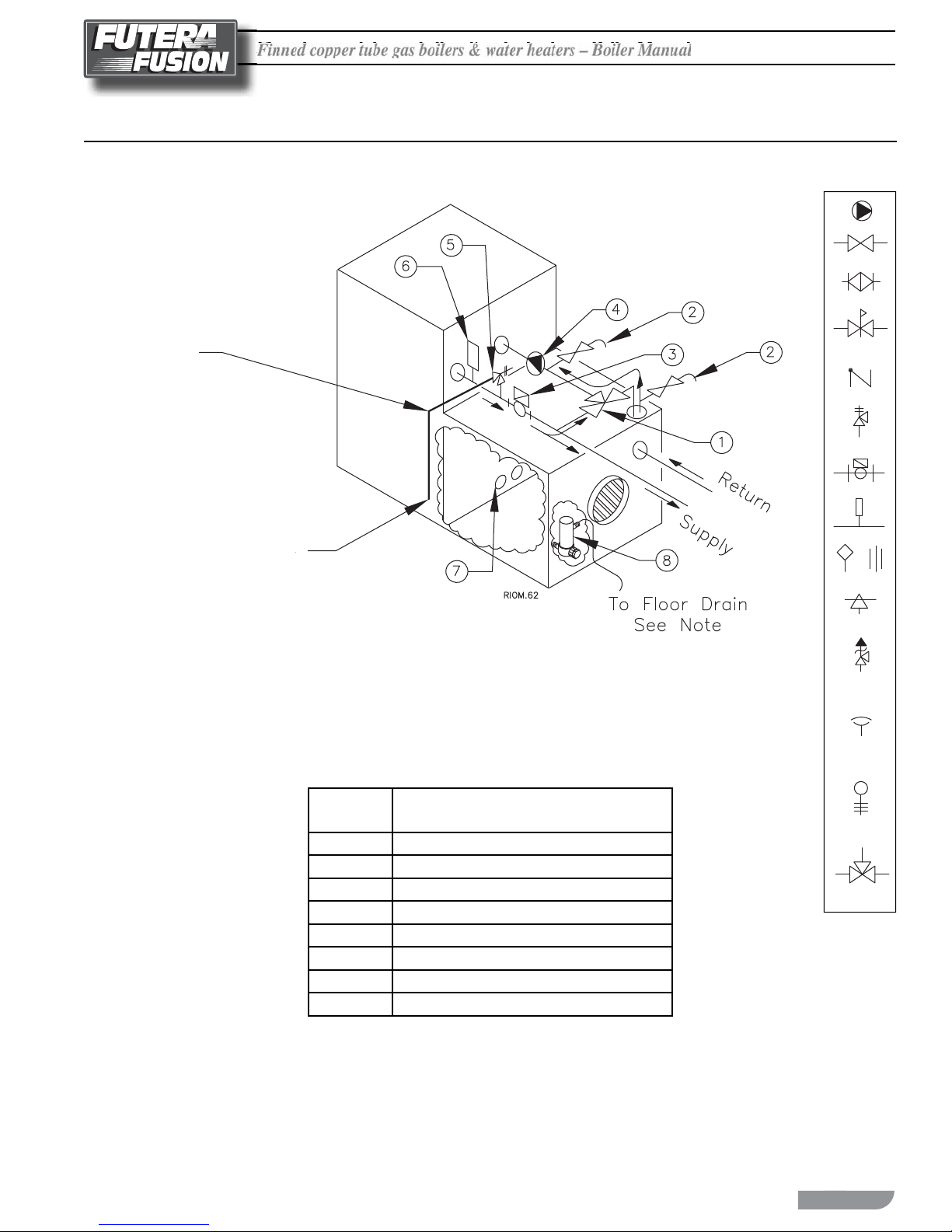
Figure 9 Futera Fusion Secondary Bypass Piping
Discharge Pipe:
Do not restrict ow.
Pipe size equal to valve outlet.
Pump
Valve
Balance Valve
Pressure
Reducing Valve
Check Valve
Pressure
Relief Valve
Flow Switch
Discharge so as to avoid exposure
of persons to hot liquid or vapor
and to allow complete drainage
of relief valve and piping.
NOTES:
1. Fill condensate drain trap with water or approved
anti-freeze solution prior to start-up.
2. Air purging valve may be located on pump or ange.
Item
Number Description
1
2
3
4
5
6
7
8
3-Way Valve
Air Purging Valves
Flow Switch
Circulator
Pressure Relief Valve
T & P Gauge
Primary Heat Exchanger Drain Valves
Condensate Drain Trap
Thermometer
Aquastat Union
Automatic
Air Vent
Temperature &
Pressure
Relief Valve
Vacuum
Relief Valve
Drain Valve
(Typ.)
3-Way
Mixing Valve
13

Fi
nned copper tube gas boilers & water heaters – Boiler Manua
l
F
F
Figure 10 Typical Primary/Secondary, Low Temperature Piping System (See Notes)
H-16 REV C
NOTES:
1. Boiler circuit piping must be sized large enough to handle maximum ow through unit.
2. Boiler and pump purging required. Air must be purged from 3-way valve after the boiler is lled. Use purge
valves provided. Purge valve may be located on pump ange. On multiple boiler installations the ow switch
may fail due to trapped air. See manual for procedure.
3. All boilers furnished with factory mounted outlet water temperature gauge.
4. For HeatNet operation, a sensor is required and installation at a minimum of 12" from the primary tee.
Notice: These drawings show suggested piping con guration, valving and are diagrammatic.
Check with local codes and ordinances for speci c requirements.
H-16 REV C
14
 Loading...