

Razor W25143499003 Installation Instructions Manual
Need Help? Visit our website at www.razor.com or call toll-free at 866-467-2967 Monday - Friday 8:00 AM - 5:00 PM PST.
Tools Required: (Not included)
A. 5 mm Allen wrench
B. 10 mm wrench
WARNING
CRAZY CART
BATTERY INSTALLATION INSTRUCTIONS
W25143499003
Do not use non-Razor products with your Razor electric
product. This item has been built to certain Razor design
specifications. Certain aftermarket parts may not be
compatible and will void your warranty.
As with all consumer electronics, use of compatible
batteries and chargers is strongly recommended. Failure
to do so may pose a fire hazard.
Examine the battery, charger and their connectors for
excessive wear or damage each time you charge the
battery. If damage or excessive wear is detected, do not
use the charger or the product until you have replaced
the worn or damaged part.
Battery connectors may contain lead and lead
compounds. Wash your hands after handling.
CAUTION: To avoid potential shock or other injury, turn power switch OFF and disconnect charger
before removing or installing the batteries. Failure to follow these steps in the correct order may cause
irreparable damage.
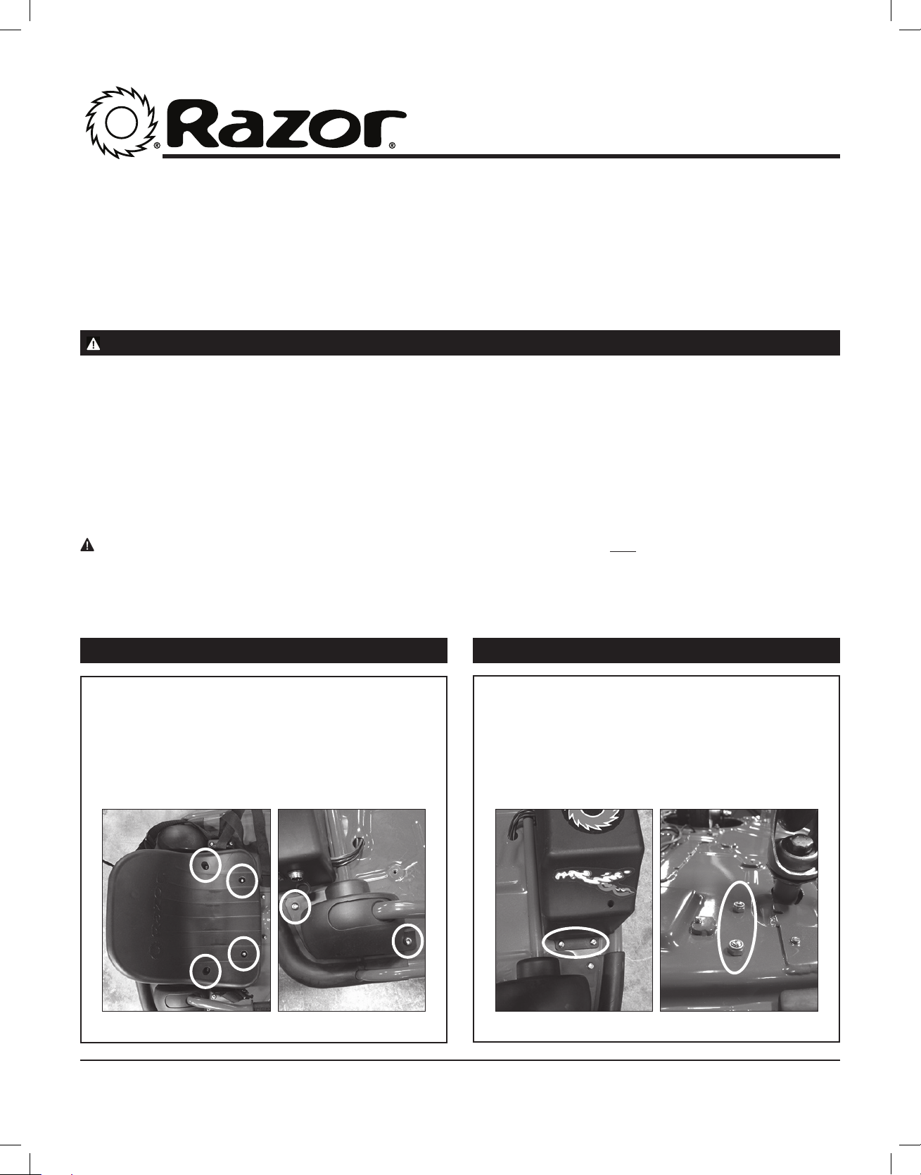
Step 1
Using a 5 mm Allen wrench, loosen the four (4) hex
bolts that attach the seat to the frame (Figure 1a)
and remove seat. Remove the two (2) hex bolts on
the Drift Bar cover (Figure 1b) and remove.
Step 2
Using a 5 mm Allen wrench and a 10 mm wrench,
loosen the two (2) hex bolts on the side of the
battery cover (Figure 2a) and the two (2) locknuts,
located underneath the unit (Figure 2b).
Figure 1a Figure 1b
1
Figure 2a Figure 2b
Need Help? Visit our website at www.razor.com or call toll-free at 866-467-2967 Monday - Friday 8:00 AM - 5:00 PM PST.
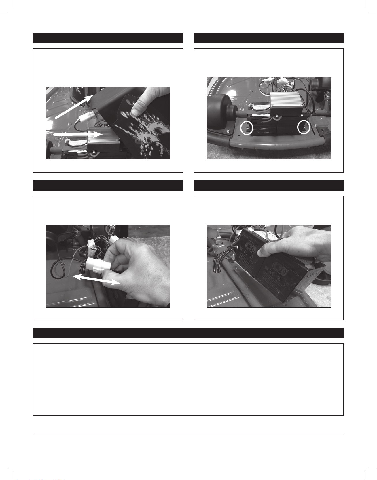
Step 3 Step 4
Remove the battery cover by lifting up the right side
first then slide off. Be careful not to pull any of the
wires that are attached to the cover.
Figure 3
Step 5
Locate the white plastic connector on the battery
that attaches to the control module and disconnect
by depressing the tab on the connector.
Using a 5 mm Allen wrench, loosen the two (2)
hex bolts on both sides of the battery bracket and
remove.
Figure 4
Step 6
Using both hands, carefully remove the batteries.
Figure 5
Figure 6
Step 7
Reverse steps 1 through 6 to install replacement batteries.
ATTENTION: Charge battery 12 hours before initial use.
2
 Loading...