

Razor RipRider 360, RipRider 360 Caster Trike, 20036501 Owner's Manual

OWNER’S MANUAL
Read and understand this entire manual before riding!
For assistance contact Razor. DO NOT RETURN TO STORE.
Item Number:
20036501
CASTER TRIKE

WARNING: Riding the RipRider 360˚ Caster Trike can be a
hazardous activity. Certain conditions may cause the equipment to fail
without fault of the manufacturer. The RipRider 360˚ Caster Trike can and is
intended to move, and it is therefore possible to lose control, fall off and/or
get into dangerous situations that no amount of care, instruction or expertise
can eliminate. If such things occur you can be seriously injured or die, even
when using safety equipment and other precautions. RIDE A
T YOUR OWN
RISK AND USE COMMON SENSE.
This manual contains many warnings and cautions concerning the
consequences of failing to maintain, inspect or properly use your RipRider
360˚ Caster T
rike. Because any incident can result in serious injury or even
death, we do not repeat the warning of potential serious injury or death each
time such a possibility is mentioned.
A
PPROPRIATE RIDER USE AND
P
ARENTAL SUPERVISION
This manual contains important safety information. It is your responsibility
to review this information and make sure that all riders understand all
warnings, cautions, instructions and safety topics and assure that young
riders are able to safely and responsibly use this product. Razor recommends
that you periodically review and reinforce the information in this manual with
younger riders, and that you inspect and maintain your children’s vehicle to
insure their safety
.
The recommended rider age of 5 and older for RipRider 360˚ Caster Trike is
only an estimate, and can be affected by the rider’s size, weight or skills. Any
rider unable to fit comfortably on the RipRider 360˚ Caster Trike should not
attempt to ride it. A parent’s decision to allow his or her child to ride
this product should be based on the child’
s maturity, skill and ability
to follow rules.
Keep this product away from small children and remember that this product
is intended for use only by persons who are, at a minimum, completely
comfortable and competent while operating the vehicle.
D
O NOT EXCEED THE WEIGHT LIMIT OF 160 pounds.
Rider weight does not necessarily mean a person’
s size is appropriate to fit
or maintain control of the RipRider 360˚ Caster Trike.
Refer to the section on safety for additional warnings.
A
CCEPTABLE RIDING PRACTICES AND
CONDITIONS
Always check and obey any local laws or regulations which may affect
the locations where the RipRider 360˚ Caster T
rike may be used on public
property. The RipRider 360˚ Caster Trike is meant to be used only in
controlled environments free of potential traffic hazards and not on public
streets. Do not ride your RipRider 360˚ Caster Trike in any areas where
pedestrian or vehicle traffic is present.
Ride defensively. Watch out for potential obstacles that could force you to
swerve suddenly or lose control. Be careful to avoid pedestrians, skaters,
skateboards, scooters, bikes, children or animals who may enter your path,
and respect the rights and property of others.
Maintain a hold on the handlebars at all times.
Never carry passengers or allow more than one person at a time to ride the
RipRider 360˚ Caster T
rike.
Never use near steps or swimming pools.
Never use headphones or a cell phone when riding.
Never hitch a ride with another vehicle.
The RipRider 360˚ Caster T
rike is intended for use on solid, flat, clean and dry
surfaces such as pavement or level ground without loose debris such as rocks
or gravel. W
et, slick or uneven and rough surfaces may impair traction and
contribute to possible accidents. Do not ride the RipRider 360˚ Caster Trike
in mud, ice, puddles or water. Avoid excessive speeds that can be associated
with downhill rides. Never risk damaging surfaces such as carpet or flooring
by use of a RipRider 360˚ Caster Trike indoors.
Do not ride at night or when visibility is impaired.
P
ROPER RIDING ATTIRE
Always wear proper protective equipment such as an approved safety
helmet, elbow pads and kneepads. A helmet may be legally required by local
law or regulation in your area. Always wear shoes, never ride barefooted or
in sandals, and keep shoelaces tied and out of the way of the wheels.
F
AILURE TO USE COMMON SENSE AND HEED THE
ABOVE WARNINGS INCREASES RISK OF SERIOUS
INJURY. USE WITH APPROPRIATE CAUTION AND
SERIOUS ATTENTION TO SAFE OPERATION.
SAFETY WARNINGS
Safety Warnings ............................................................ 1
Before You Begin ........................................................... 2
Assembly and Set-Up ................................................. 3-4
Repair and Maintenance ................................................ 5
1
T
roubleshooting Guide ................................................... 5
R
ipRider 360˚ Caster Trike Parts .................................... 6
Safety Reminders .......................................................... 7
Warranty ........................................................................ 7
CONTENTS
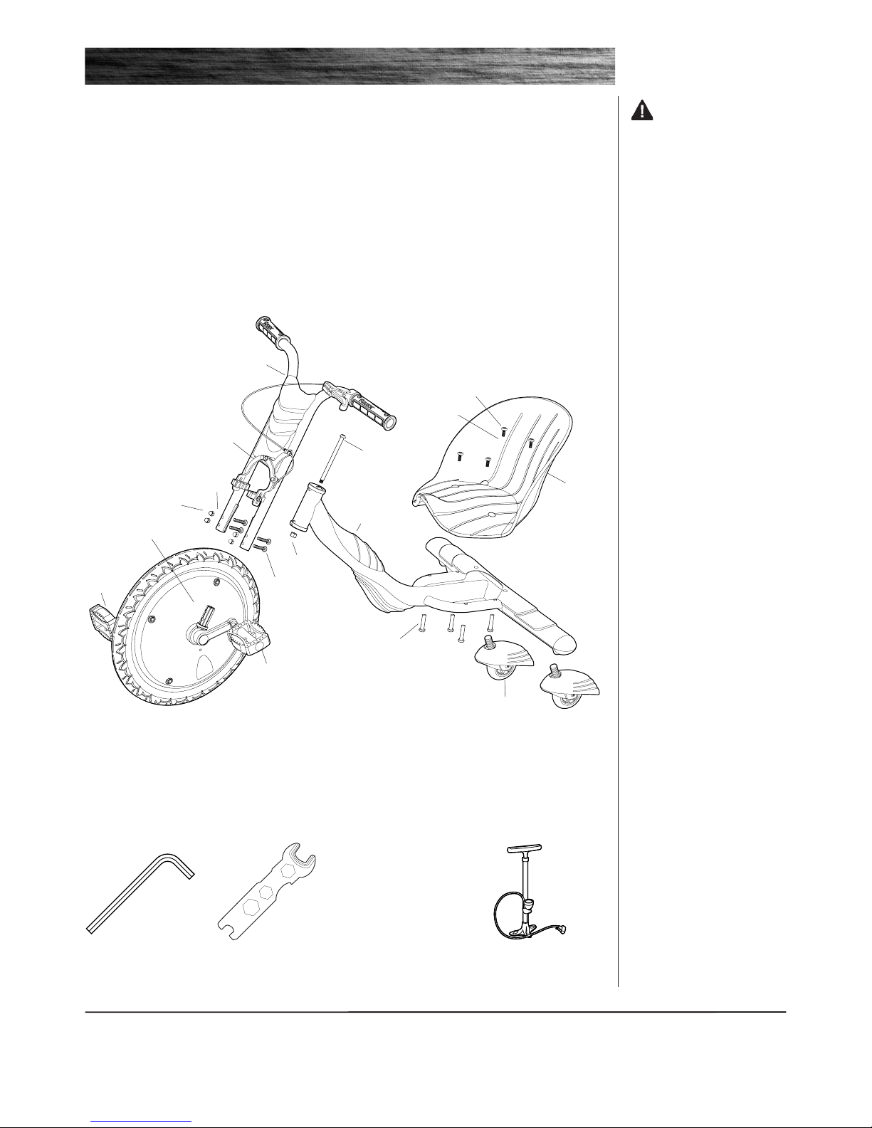
Remove contents from box and check parts against part diagram below. Remove the foam separators that protect the
components from damage during shipping. Inspect the contents of the box for scratches in the paint, dents or kinked
cables that may have occurred during shipping. Because the Rip Rider 360˚ was partially assembled and packed at the
factory
, there should not be any problems, even if the box has a few scars or dents.
❑ Estimated Assembly and Set-Up Time
Razor recommends assembly by an adult with experience in bicycle mechanics.
Allow up to 15–20 minutes for assembly.
BEFORE YOU BEGIN
2
WARNING: DO
NOT USE NON-RAZOR
PRODUCTS WITH YOUR
RIPRIDER 360˚.
The RipRider 360˚ has been built to
certain Razor design specifications.
The original equipment supplied at
the time of sale was selected on
the basis of its compatibility with
the frame, fork and all other parts.
Certain aftermarket products may
or may not be compatible.
❑ Required Tools
Some tools are supplied; however, we recommend the use of mechanic’s grade tools. Use the supplied tools only as a
last resort.
Need Help? Visit our web site for replacement parts, product support, live chat and a list of
authorized service centers at www.razor.com or call toll-free at 866-467-2967 Monday - Friday
8
:00 AM - 5:00 PM Pacific Time.
(2) 5mm
hexagonal key wrenches
(included)
Bicycle-style tire pump
for Schrader valve tires,
with pressure gauge
10mm, 13mm and 15mm
open end wrenches
(included)
Front Fork Assembly
Front Wheel Assembly
Seat
Rear Castor
Wheels
Steering Bolt
Front Caliper Brake
Locknut
Allen Socket Screw
W
asher
Allen Long Screw
Combinatory Nut
W
asher
Allen Socket Screw
Left Pedal
Right
Pedal
Frame
Assembly
3
ASSEMBLY AND SET-UP
WARNING: Failing to
properly tighten the steering bolt
that attaches the handlebar can
cause you to lose control and fall.
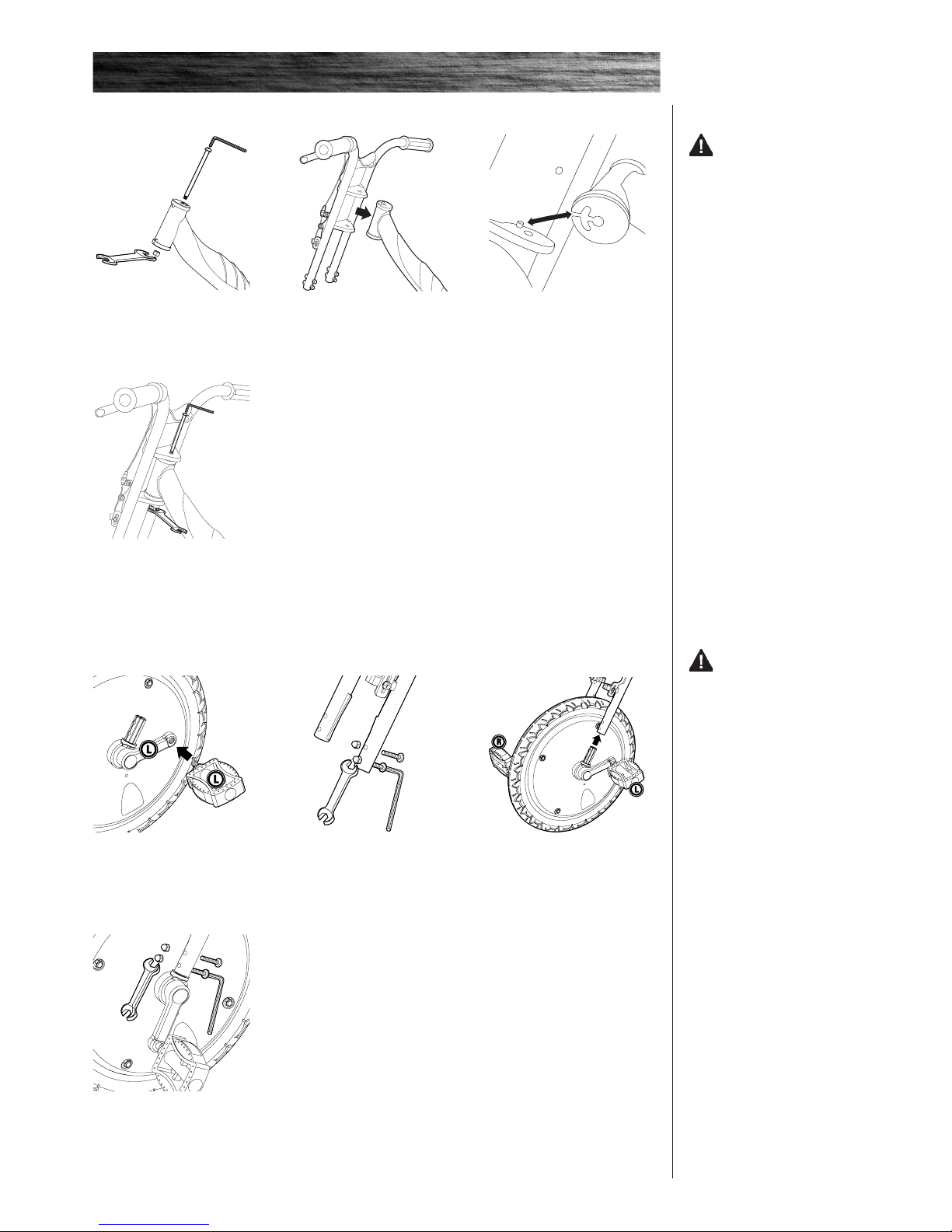
2 Remove the four Allen socket
screws and nuts from the front
fork with a 10mm open wrench
and 5mm hexagonal wrench.
3 Insert the wheel assembly into
the front fork assembly and align
holes.
Note: Refer to R (right) and L (left)
stickers on pedals for orientation.
❑ Attaching the Pedals and Front Wheel
4 Re-insert the Allen socket
screws through the front fork and
secure with nuts. T
ighten nuts with
a 10mm open wrench and 5mm
hexagonal wrench.
1 Remove the steering bolt and
locknut from the frame assembly
with a 13mm open wrench and
5mm hexagonal wrench.
2 Insert the front fork assembly
into the frame assembly.
❑ Attaching the Front Fork
4 Re-insert the steering bolt and
secure with locknut using a 13mm
open wrench and 5mm hexagonal
wrench.
1 Install the left pedal into the
crank marked (L). Tighten with
15mm open end wrench. Repeat
step for right pedal and crank.
3 Be sure to align slot in headset
tube with pin on fork properly as
shown.
WARNING: Failing to
install the correct pedal on the
correct crank (left and right) can
cause the pedal to strip.
4
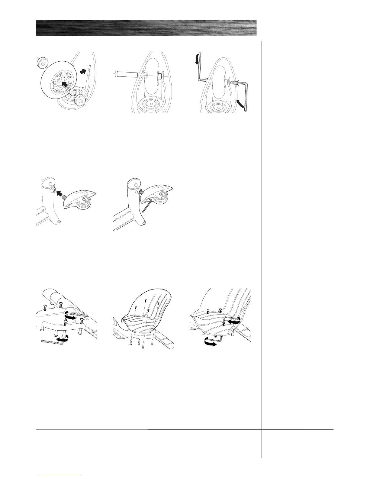
4 Locate the threaded hole
on the rear underside of frame.
Screw caster wheel into hole.
5 Tighten with 5mm hexagonal
wrench.
❑ Attaching the Rear Caster Wheels
1 Remove the four Allen socket
screws and Allen long screws
from the frame with two 5mm
hexagonal wrenches. One on top
and one on bottom.
2 Align four holes in seat with
four holes in frame. Insert Allen
long screws through the bottom of
the frame.
❑ Attaching the Seat
ASSEMBLY AND SET-UP
3 Secure with Allen socket
screws. Tighten screws with two
5mm hexagonal wrenches. One on
top and one on bottom.
2 Insert one small spacer between
wheel and caster and align holes.
Insert axle bolt through caster
, small
spacer, wheel and into small spacer
on other side of wheel.
Need Help? Visit our web site for replacement parts, product support, live chat and a list of
authorized service centers at www.razor.com or call toll-free at 866-467-2967 Monday - Friday
8
:00 AM - 5:00 PM Pacific Time.
3 Insert Allen socket screw
through caster, small spacer and
into axle bolt. Tighten with 5mm
hexagonal wrench on both sides.
1 Insert large spacer into wheel
and insert bearings into each side
of wheel. Make sure all holes are
aligned. Insert wheel into caster
.
Vehicle runs sluggishly
Vehicle does not stop when
applying the brake
P
roblem Possible Cause Solution
Front tire is not properly inflated
Brake is not adjusted properly
The tire is infl
ated when shipped, but it will invariably will lose some
pressure between the point of manufacturing and your purchase.
Refer to tire inflation instructions above.
Refer to adjusting the brakes instructions above.
TROUBLESHOOTING GUIDE
5
REPAIR AND MAINTENANCE
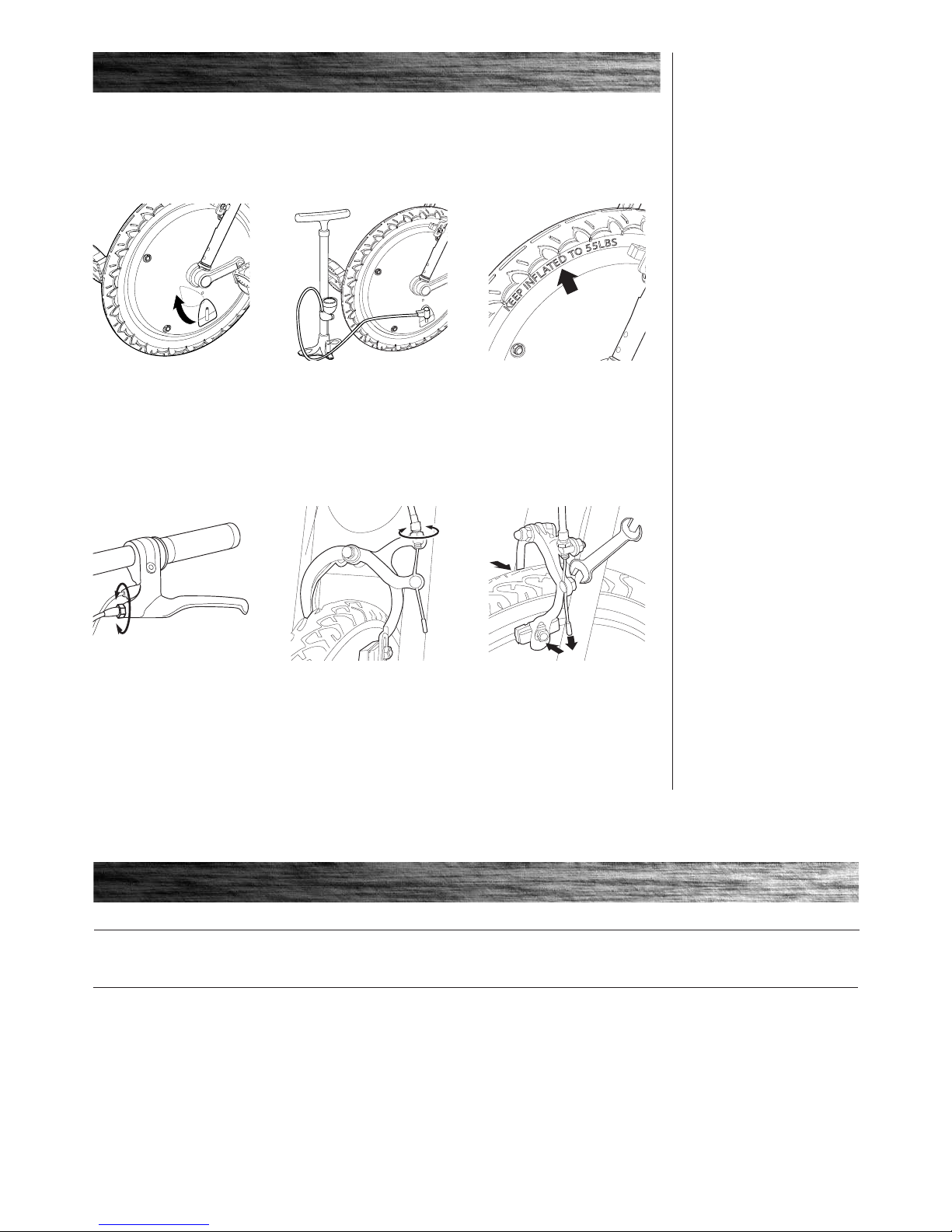
1 Slide the panel on the wheel
cover to the side to expose
tire valve.
Note: The pressurized air supplies
found at gasoline stations are
designed to inflate high-volume
automobile tires. If you decide to
use such an air supply to inflate
your RipRider 360˚ Caster T
rike tire,
first make sure the pressure gauge
is working, then use very short
bursts to inflate to the correct PSI.
If you inadvertently over
-inflate the
tire, release the excess pressure
immediately.
Check the Razor web site for any updates on the latest repair and maintenance procedures.
❑ Inflating the Tires
The front tire is inflated when shipped, but it will invariably lose some pressure between the point of manufacturing
and your purchase.
2 Use a bicycle style tire pump
equipped for a Schrader-type valve.
❑ Adjusting the Brakes
1 To adjust the brake play, thread
the brake lever adjuster in or out 1/4
to 1/2 turn until the desired brake
adjustment is attained. Most
adjustments are complete at this
step. If brake still needs further
adjustment, proceed to step 2.
2 If the brake lever adjuster is
threaded outward and the brake
still has too much slack, use the
front caliper brake adjuster for
additional adjustment.
3 Inflate the front tire to the lbs.
indicated on the sidewall of tire.
3 If brake still has too much slack,
adjust the brake cable by loosening
the nut that secures the cable with
a 10mm wrench. Pull the brake
closed so the pads almost touch
the wheel. Pull cable tight and
tighten the nut.
 Loading...