


Raytheon RMPA2000-58 Datasheet
Raytheon RF Components
362 Lowell Street
Andover, MA 01810
Revised April 7, 2000
Page 1
www.raytheon.com/micro
Characteristic performance data and specifications are subject to change without notice.
PRODUCT INFORMATION
Description
Parameter Min Typ Max Unit
Frequency Range 1800 1900 2000 MHz
Gain
1,2,3
30 dB
Output Power, P1dB
1,3
28 dBm
Ass.Power Added Efficiency 35 %
Output Power, P1dB
4
31 dBm
Ass. Power added efficiency 40 %
Input Return Loss (50Ω)7.5 dB
40% Power Added Efficiency
31 dBm Output Power, typical, at Vd = +7V
28 dBm Output Power, typical, at Vd = +5V
No external RF matching components
Small Package Outline: 0.28” x 0.28” x 0.07”
Features
Notes:
1. Idq=300mA, Vd1=Vd2=5.0V
2. Pin=-3dBm
3. Production testing includes Gain, Output power and input return loss at
Vd1=Vd2=5.0V, Vg1=Vg2=-0.5V (nominal), adjusted for Idq=300mA, Pin=-3dBm and at F=1.90 GHz.
4. Vd1=Vd2=+7V, Idq=400mA
Electrical
Characteristics
At 25ºC, Zo = 50 ohms,
unless otherwise stated
The Raytheon RMPA2000-58 is a fully monolithic power amplifier in a surface mount package for use in wireless
applications in the 1.8 to 2.0 GHz ISM frequency band. The amplifier may be biased for linear, class AB or class F
for high efficiency applications. On-chip matching components allow operation in a 50-ohm system with no
external matching components. The MMIC utilizes Raytheon’s 0.25
µm power pHEMT process.
Rating Symbol Value Unit
DC Supply Voltage V
DD
+8 Volts
DC Negative Bias Voltage V
GG
-5 Volts
RF Input Power (from (50Ω source) P
IN
10 dBm
Drain to Source current Ids 700 mA
Gate current Ig 5 mA
Channel temperature Tch 150 °C
Operating Case Temperature Range T
C
-40 to 100 °C
Storage Temperature Range T
S
-40 to 125 °C
Absolute
Maximum
Ratings
PMBG12 Package
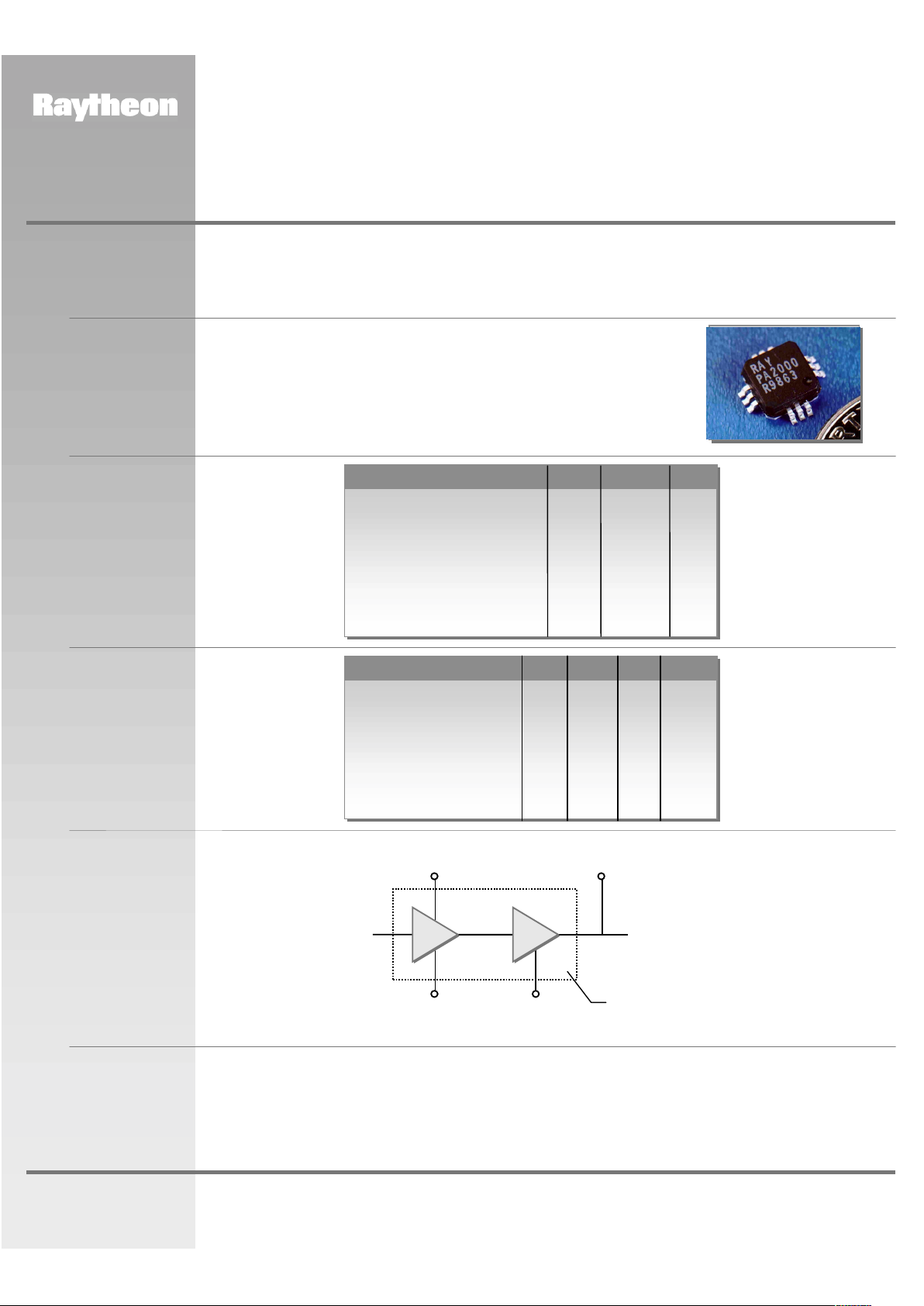
Functional
Block Diagram
V
DD
Pin #4
RF
IN
Pin #8
RF
OUT
Pin #2
V
D1
Pin #5
V
G2
Pin #11
V
G1
Pin #10
RMPA2000-58
1.8-2.0 GHz GaAs MMIC
Power Amplifier

Raytheon RF Components
362 Lowell Street
Andover, MA 01810
Revised April 7, 2000
Page 2
www.raytheon.com/micro
Characteristic performance data and specifications are subject to change without notice.
PRODUCT INFORMATION
Figure 1
Package Outline and
Pin Designations
GND
RF Out
GND
Vd2
Vd1
GND
GND
RF Input
GND
Vg1
Vg2
GND
GND (METAL BASE)
1
2
3
4
5
6
7
8
9
10
11
12
13
DescriptionPin #
Dimensions in inches
10
11
1
2
3
456
7
8
9
12
BOTTOM VIEW
TOP VIEW
10
11
0.030
A
0.015
1
2
3
456
7
8
9
12
0.200 SQ.
RAY
RMPA
2000
0.041
13
PLASTIC LID
SIDE SECTION
0.075 MAX.
0.010
0.230
0.246
0.282
RMPA2000-58
1.8-2.0 GHz GaAs MMIC
Power Amplifier