

Page 1
TX
Infrared Sensor
Operating Instructions
Rev. O7 07/2017
50501
1.888.610.7664 info@Raytek-Direct.com
Page 2

COMPLIANCE STATEMENT
The device complies with the requirements of the European Directives:
EC – Directive 2014/30/EU – EMC
EC – Directive 2011/65/EU – RoHS II
EC – Directive 2014/34/EU – ATEX
valid for device: xxxTXxxxxxIS4, xxxTXxxxxxIS4W, xxxTXxxxxxIS5,
xxxTXxxxxxIS5W
EN 61326-1: 2013 Electrical measurement, control and laboratory devices -
Electromagnetic susceptibility (EMC)
EN 50581: 2012 Technical documentation for the evaluation of electrical products with respect
to restriction of hazardous substances (RoHS)
EN 60079-0: 2012 Risk of explosion – part 0: general requirements (ATEX)
EN 60079-11: 2012 Risk of explosion – part 11: device protection by intrinsic safety “I” (ATEX)
Electromagnetic Compatibility Applies to use in Korea only. Class A
Equipment (Industrial Broadcasting & Communication Equipment)
This product meets requirements for industrial (Class A) electromagnetic wave equipment and
the seller or user should take notice of it. This equipment is intended for use in business
environments and is not to be used in homes.
1.888.610.7664 info@Raytek-Direct.com
Page 3

Content
COMPLIANCE STATEMENT .......................................................................................................................... 5
CONTENT ............................................................................................................................................................ 6
1 SAFETY INSTRUCTIONS ............................................................................................................................. 8
2 TECHNICAL DATA ........................................................................................................................................ 9
2.1 MODELS AND PARAMETERS ......................................................................................................................... 9
2.2 OPTICAL DIAGRAMS .................................................................................................................................. 10
2.3 SCOPE OF DELIVERY ................................................................................................................................... 12
3 BASICS ............................................................................................................................................................. 13
3.1 MEASUREMENT OF INFRARED TEMPERATURE .......................................................................................... 13
3.2 DISTANCE AND SPOT SIZE ......................................................................................................................... 13
3.3 AMBIENT TEMPERATURE ........................................................................................................................... 13
3.4 ATMOSPHERIC QUALITY ............................................................................................................................ 14
3.5 ELECTRICAL INTERFERENCE ...................................................................................................................... 14
3.6 EMISSIVITY OF TARGET OBJECT.................................................................................................................. 14
4 INSTALLATION ............................................................................................................................................ 15
4.1 WIRE PARAMETERS FOR CURRENT LOOP .................................................................................................. 15
4.2 DIMENSIONS OF SENSOR ............................................................................................................................ 16
4.2.1 Fixed Brackets ..................................................................................................................................... 16
4.3 CONNECTING THE SIGNAL LINE ................................................................................................................ 16
4.4 BASIC MODEL ............................................................................................................................................. 19
4.4.1 Installation with a Controller ............................................................................................................. 19
4.5 SMART MODEL ........................................................................................................................................... 19
4.5.1 HART Protocol ................................................................................................................................... 19
4.5.2 HART/RS232 Adapter ....................................................................................................................... 20
4.5.3 Installation of Smart Model ................................................................................................................ 20
4.5.4 Address Assignment for Multiple Sensors ......................................................................................... 21
4.5.5 Installation of Multiple Sensors (digital, address mode) .................................................................... 22
4.5.6 Installation of Multiple Sensors (digital and analog, address mode) .................................................. 23
4.5.7 Installation of Multiple Sensors (digital and analog, tag mode) ........................................................ 23
4.5.8 Alarm Output ..................................................................................................................................... 24
5 OPTIONS ......................................................................................................................................................... 25
5.1 AIR/WATER-COOLED HOUSING ................................................................................................................ 25
5.1.1 Connecting .......................................................................................................................................... 26
5.1.2 Avoidance of Condensation ................................................................................................................ 26
5.2 ATEX INTRINSIC SAFETY ........................................................................................................................... 28
6 ACCESSORIES ............................................................................................................................................... 29
6.1 OVERVIEW .................................................................................................................................................. 29
6.2 ADJUSTABLE BRACKET ............................................................................................................................... 30
6.3 AIR PURGE COLLAR ................................................................................................................................... 30
6.4 RIGHT ANGLE MIRROR .............................................................................................................................. 30
6.5 SIGHTING VIEWER ...................................................................................................................................... 31
6.6 PIPE ADAPTER ............................................................................................................................................ 31
6.7 ADJUSTABLE PIPE ADAPTER ...................................................................................................................... 32
1.888.610.7664 info@Raytek-Direct.com
Page 4

6.8 THERMOJACKET .......................................................................................................................................... 32
6.9 INDUSTRIAL POWER SUPPLY ...................................................................................................................... 34
6.10 PROTECTIVE WINDOW .............................................................................................................................. 35
6.11 USB/RS232 ADAPTER .............................................................................................................................. 36
7 SOFTWARE ..................................................................................................................................................... 37
7.1 REQUIREMENTS ........................................................................................................................................... 37
7.2 INSTALLATION AND START ........................................................................................................................ 37
7.3 SENSOR SETUP............................................................................................................................................. 38
8 MAINTENANCE ............................................................................................................................................ 39
8.1 TROUBLESHOOTING MINOR PROBLEMS ..................................................................................................... 39
8.2 AUTOMATIC ERROR INDICATION ............................................................................................................... 39
8.3 CLEANING THE LENS .................................................................................................................................. 40
8.4 REPLACING A PROTECTIVE WINDOW ........................................................................................................ 40
8.4.1 Models produced after May 1999 ........................................................................................................ 40
8.4.2 Models produced before May 1999 ...................................................................................................... 41
9 APPENDIX ....................................................................................................................................................... 42
9.1 DETERMINATION OF EMISSIVITY ................................................................................................................ 42
9.2 TYPICAL EMISSIVITY VALUES ..................................................................................................................... 42
9.3 DISPLAY MONITOR ..................................................................................................................................... 46
9.3.1 Installation with the Sensor ................................................................................................................ 46
9.4 ATEX CERTIFICATE OF CONFORMITY ........................................................................................................ 47
NOTES
1.888.610.7664 info@Raytek-Direct.com
Page 5
Safety Instructions
8 Rev. O7 07/2017 TX
1 Safety Instructions
This document contains important information, which should be kept at all times with the instrument
during its operational life. Other users of this instrument should be given these instructions with the
instrument. Eventual updates to this information must be added to the original document. The
instrument can only be operated by trained personnel in accordance with these instructions and local
safety regulations.
Acceptable Operation
This instrument is intended only for the measurement of temperature. The instrument is appropriate
for continuous use. The instrument operates reliably in demanding conditions, such as in high
environmental temperatures, as long as the documented technical specifications for all instrument
components are adhered to. Compliance with the operating instructions is necessary to ensure the
expected results.
Unacceptable Operation
The instrument should not be used for medical diagnosis.
Replacement Parts and Accessories
Use only original parts and accessories approved by the manufacturer. The use of other products can
compromise the operation safety and functionality of the instrument.
Instrument Disposal
Disposal of old instruments should be handled according to professional and
environmental regulations as electronic waste.
Operating Instructions
The following symbols are used to highlight essential safety information in the operation instructions:
Helpful information regarding the optimal use of the instrument.
Warnings concerning operation to avoid instrument damage and personal injury.
Incorrect use of 110 / 230 V electrical systems can result in electrical hazards and personal
injury. All instrument parts supplied with electricity must be covered to prevent physical
contact and other hazards at all times.
For ATEX certified units comply with the installation and safety instructions for electrical
equipment in potentially explosive atmospheres.
1.888.610.7664 info@Raytek-Direct.com
Page 6

Technical Data
TX Rev. O7 07/2017 9
2 Technical Data
2.1 Models and Parameters
In general, there are two models available. The basic model (TXC, for °C, and TXF, for °F) and the Smart model (TXS).
The model descriptor is followed by the description for the optical characteristic, see following page):
Optical characteristic LTPSF LTSF MTSF G5SF (Glass) P7SF (Plastics) HTSF
Temperature range (°C) - 18 to 500 - 18 to 500 200 to 1000 250 to 1650 10 to 360 500 to 2000
Temperature range (°F) 0 to 1000 0 to 1000 400 to 1800 500 to 3000 50 to 650 950 to 3600
Optical resolution (90%) 15 : 1 33 : 1 33 : 1 33 : 1 33 : 1 60 : 1
Spectral response (µm) 8 to 14 8 to 14 3.9 5.0 7.9 2.2
Close focus CF CF1, CF2 CF1, CF2 CF1, CF2
Thermal Parameters
Accuracy ± 1 % of reading or ± 1.4°C (2.5°F), whichever is greater
(at 23°C ± 5°C (73°F ± 9°F) ambient temperature)
Repeatability ± 0.5 % of reading or ± 0.7°C, whichever is greater
Detector Micromachined Thermopile
Response time (95 %) 165 ms (100 ms HT models)
Temperature resolution (NET) 0.1 K (LT models), 1K (all other models)
Emissivity 0.10 to 1.00 (all models)
Electrical Parameters
Output 4 to 20 mA
Maximum loop impedance 750 Ohm
Alarm 24 V / 150 mA (only Smart models)
Signal processing
Smart models °C/°F, Averaging, Peak/Valley Hold,
Emissivity, internal housing temperature, external ambient temperature
Basic model Emissivity
Power 24 VDC ± 10 %, max. 21 mA, if HART communication is required,
otherwise 12 to 24 VDC +20 %
General Parameters
Environmental rating IP 65, IEC 529, NEMA 4
Ambient operating range without cooling 0 to 70°C (32 to 160°F)
with air cooling max. 120°C (250°F)
with water cooling max. 175°C (350°F)
with ThermoJacket max. 315°C (600°F)
Storage temperature - 18°C to 85°C (0 to 185°F)
Relative Humidity 10% to 95% non-condensing
Vibration IEC 68-2-6 (MIL STD 810D), 3 axis, 11 to 200 Hz, 3 G
Shock IEC 68-2-27 (MIL STD 810D), 3 axis, 11 ms, 50 G
Dimensions / Weight Sensor L: 187 mm; Ø: 42 mm / 330 g (Length 7.36 inches, dia 1.65 inches)
with water cooling L: 187 mm; Ø: 60 mm / 595 g (Length 7.36 inches, dia 2.36 inches)
1.888.610.7664 info@Raytek-Direct.com
Page 7

Technical Data
10 Rev. O7 07/2017 TX
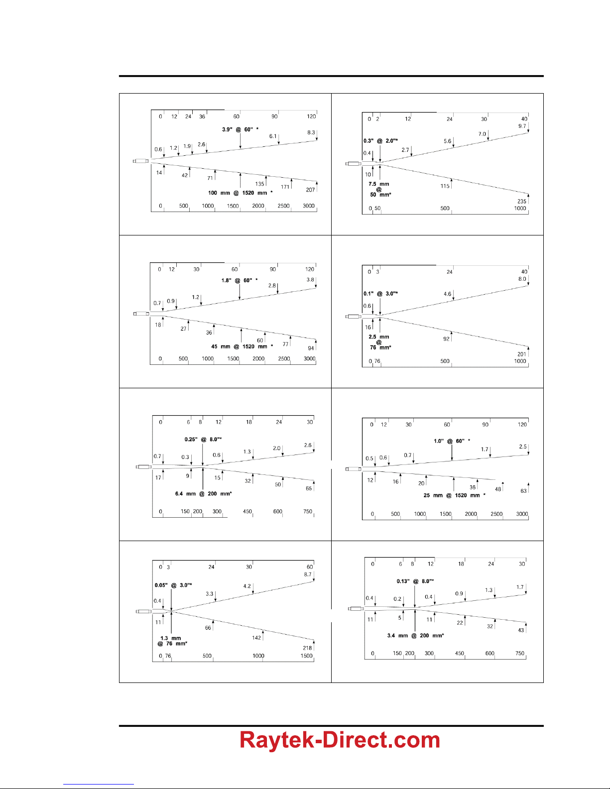
2.2 Optical Diagrams
The optical diagrams indicate the target spot diameter at any given distance between the target object
and the sensing head.
All target spot sizes indicated in the optical diagrams are based on 90% energy.
Figure 1: How to read the optical diagrams
Target Spot Diameter
(S) and Measuring
Distance (D) in Close
Focus in inches
Target Spot Diameter S (in)
Distance D (in)
Target Spot Diameter
(S) and Measuring
Distance (D) in Close
Focus in mm
Target Spot Diameter S (mm)
Distance D (mm)
Distance between Sensor and Object [in]
Distance between Sensor and Object [mm]
Close Focus D : S = Proportion between Distance (D) to Target Spot
and Target Spot Diameter (S) in Close Focus
Far Field D : S = Proportion with Distances 10 times greater than the
Close Focus Distance
Calculating the Target Spot Size
To calculate the target spot size from two known points within an
optical diagram the following formula can be used:
nf
nf
nx
nx
SS
DD
DD
SS
Sx = unknown diameter of target spot
Sn = smallest known diameter of target spot
Sf = greatest known diameter of target spot
Dx = distance to unknown target spot
Dn = distance to smaller known target spot
Df = distance to greater known target spot
1.888.610.7664 info@Raytek-Direct.com
Page 8
Technical Data
TX Rev. O7 07/2017 11
Plastic Lens, Standard Focus SF
Plastic Lens, Close Focus CF
Low and Medium Temperature Ranges,
G5 (Glass), P7 (Plastic), Standard Focus SF
Low and Medium Temperature Ranges,
High Resolution, Close Focus CF1
Low and Medium Temperature Ranges,
High Resolution, Close Focus CF2
High Temperature, Standard Focus SF
High Temperature, Close Focus CF1
High Temperature, Close Focus CF2
Figure 2: Optical Diagrams
LTSF, MTSF,
G5SF, P7SF
LTPSF
LTPCF1
LTCF1, MTCF1
HTSF
HTCF2
HTCF1
* Focus Point D:S = 15:1 Far Field D:S = 14:1
Distance D Sensor to Object [in]
Distance D Sensor to Object [mm]
Spot Dia. [mm]
Spot Dia. [in]
* Focus Point D:S = 7:1 Far Field D:S = 4:1
Distance D Sensor to Object [in]
Distance D Sensor to Object [mm]
Spot Dia. [mm]
Spot Dia. [in]
* Focus Point D:S = 33:1 Far Field D:S = 30:1
Distance D Sensor to Object [in]
Distance D Sensor to Object [mm]
Spot Dia. [mm]
Spot Dia. [in]
* Focus Point D:S = 30:1 Far Field D:S = 5:1
Distance D Sensor to Object [in]
Distance D Sensor to Object [mm]
Spot Dia. [mm]
Spot Dia. [in]
* Focus Point D:S = 32:1 Far Field D:S = 10:1
Distance D Sensor to Object [in]
Distance D Sensor to Object [mm]
Spot Dia. [mm]
Spot Dia. [in]
* Focus Point D:S = 60:1 Far Field D:S = 42:1
Distance D Sensor to Object [in]
Distance D Sensor to Object [mm]
Spot Dia. [mm]
Spot Dia. [in]
* Focus Point D:S = 60:1 Far Field D:S = 7:1
Distance D Sensor to Object [in]
Distance D Sensor to Object [mm]
Spot Dia. [mm]
Spot Dia. [in]
* Focus Point D:S = 60:1 Far Field D:S = 14:1
Distance D Sensor to Object [in]
Distance D Sensor to Object [mm]
Spot Dia. [mm]
Spot Dia. [in]
1.888.610.7664 info@Raytek-Direct.com
Page 9

Technical Data
12 Rev. O7 07/2017 TX
2.3 Scope of Delivery
All models are provided with:
operator´s manual
a fixed bracket
mounting nut
models have 4 to 20 mA output
1.888.610.7664 info@Raytek-Direct.com
Page 10
Basics
TX Rev. O7 07/2017 13
3 Basics
3.1 Measurement of Infrared Temperature
Everything emits an amount of infrared radiation according to its surface temperature. The intensity of
the infrared radiation changes according to the temperature of the object. Depending on the material
and surface properties, the emitted radiation lies in a wavelength spectrum of approximately 1 to 20
µm. The intensity of the infrared radiation (”heat radiation”) is dependent on the material. For many
substances this material-dependent constant is known. It is referred to as ”emissivity value”, see
appendix see section 9.2 Typical Emissivity Values, page 42.
Infrared thermometers are optical-electronic sensors. These sensors are able to detect ”radiation of
heat”. Infrared thermometers are made up of a lens, a spectral filter, a sensor, and an electronic signal
processing unit. The task of the spectral filter is to select the wavelength spectrum of interest. The sensor
converts the infrared radiation into an electrical parameter. The connected electronics generate electrical
signals for further analysis. As the intensity of the emitted infrared radiation is dependent on the
material, the required emissivity can be selected on the sensor.
The biggest advantage of the infrared thermometer is its ability to measure in the absence of contact.
Consequently, surface temperatures of moving or hard to reach objects can easily be measured.
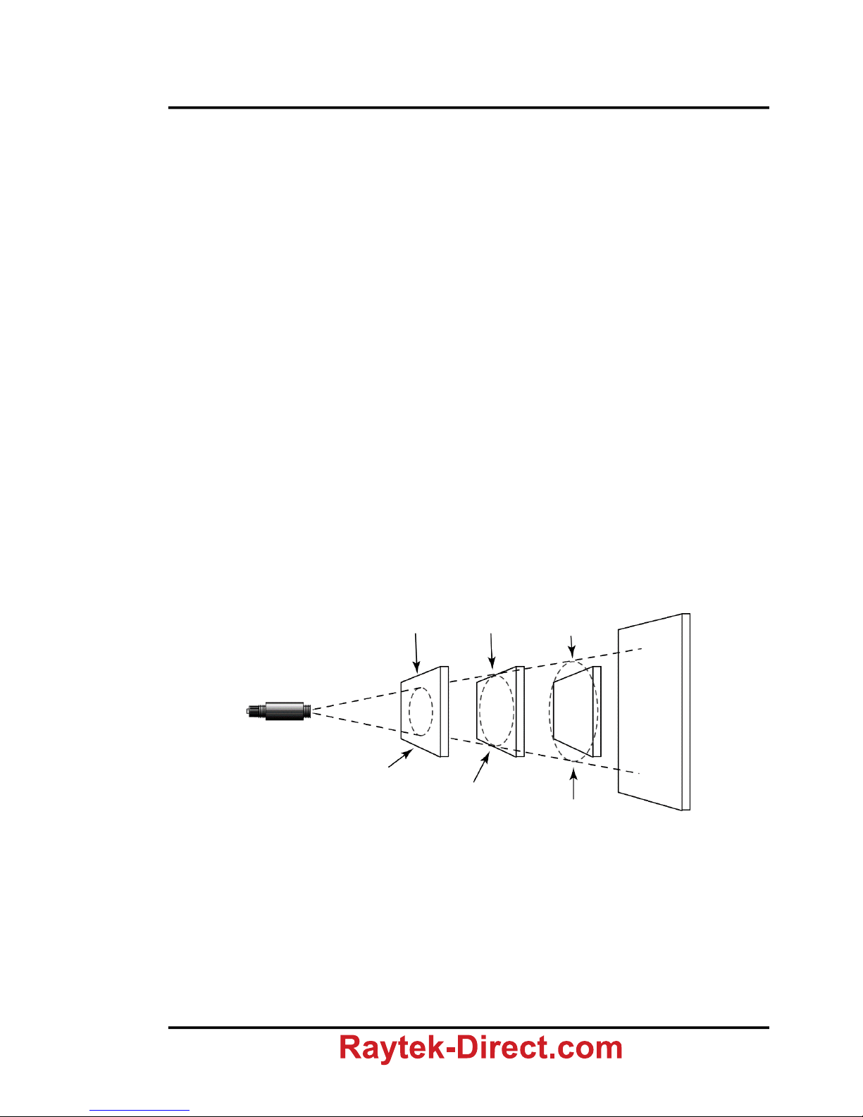
3.2 Distance and Spot Size
The desired spot size on the target will determine the maximum measurement distance and the
necessary focus length of the optical module. To avoid erroneous readings the target spot size must
contain the entire field of view of the sensor. Consequently, the sensor must be positioned so the field
of view is the same as or smaller than the desired target size. For a list indicating the available focus
models and their parameters see Figure 2: Optical Diagrams on page 11.
Figure 3: Proper Sensor Placement
3.3 Ambient Temperature
The sensing head is designed for measurements in ambient temperatures between 0°C and 70°C (32 to
160°F). In ambient conditions above 70°C (160°F), a water or air cooled housing is available to extend
the operating range to 120°C (250°F) with air cooling and to 175°C (350°F) with water cooling. When
using the water cooled housing, it is strongly recommended to use the supplied air purge collar to avoid
condensation on the lens. In ambient conditions up to 315°C (600°F), the ThermoJacket housing should
be used.
Target greater than spot size
Target greater equal to spot size
Target smaller than spot size
Background
1.888.610.7664 info@Raytek-Direct.com
Page 11

Basics
14 Rev. O7 07/2017 TX
3.4 Atmospheric Quality
In order to prevent damage to the lens and erroneous readings, the lens should always be protected
from dust, smoke, fumes, and other contaminants. For this purpose an air purge collar is available. You
should only use oil free, clean “instrument“ air.
3.5 Electrical Interference
To minimize electrical or electromagnetic interference, follow these precautions:
Mount the sensor as far away as possible from possible sources of interference such as
motorized equipment producing large step load changes.
Ensure a fully insulated installation of the sensor (Avoid ground loops!).
Make sure the shield wire in the sensor cable is earth grounded at one location.
3.6 Emissivity of Target Object
Determine the emissivity of the target object as described in appendix 9.1 Determination of Emissivity
on page 42. If emissivity is low, measured results could be falsified by interfering infrared radiation
from background objects (such as heating systems, flames, fireclay bricks, etc. close beside or behind
the target object). This type of problem can occur when measuring reflecting surfaces and very thin
materials such as plastic films and glass.
This measuring error when measuring objects with low emissivity can be reduced to a minimum if
particular care is taken during installation, and the sensing head is shielded from these reflecting
radiation sources.
1.888.610.7664 info@Raytek-Direct.com
Page 12

Installation
TX Rev. O7 07/2017 15
4 Installation
The infrared sensor provides a standard two-wire current loop output and has been designed for use in
harsh industrial environments. The Smart model allows the remote programming of the temperature
range, alarm values and other functions.
4.1 Wire Parameters for Current Loop
You should use shielded twisted pairs or multiple twisted pairs with a joint shield.
Line length
The maximum line length of one two-wire line per loop is dependent on the loop resistance (R), the
capacitance per length unit (C), and the capacitance of the sensor CS (5000 pF). It is calculated as follows:
C
10000C
CR
1065
l
S
6
For simplifying the formula use, the parameters must be provided as “naked values” (in the given
dimension)!
Typical values for wire cross sections (copper)
up to 250 m line length: 0.2 mm
2
cross section AWG24
up to 650 m line length: 0.5 mm
2
cross section AWG20
up to 1500 m multiple wire line lengths: 1.5 mm
2
cross section
up to 3000 m single wire line lengths: 2.5 mm
2
cross section
l … in meter
R … in Ohm
C … in pF / m
CS … in pF
1.888.610.7664 info@Raytek-Direct.com
Page 13
Installation
16 Rev. O7 07/2017 TX
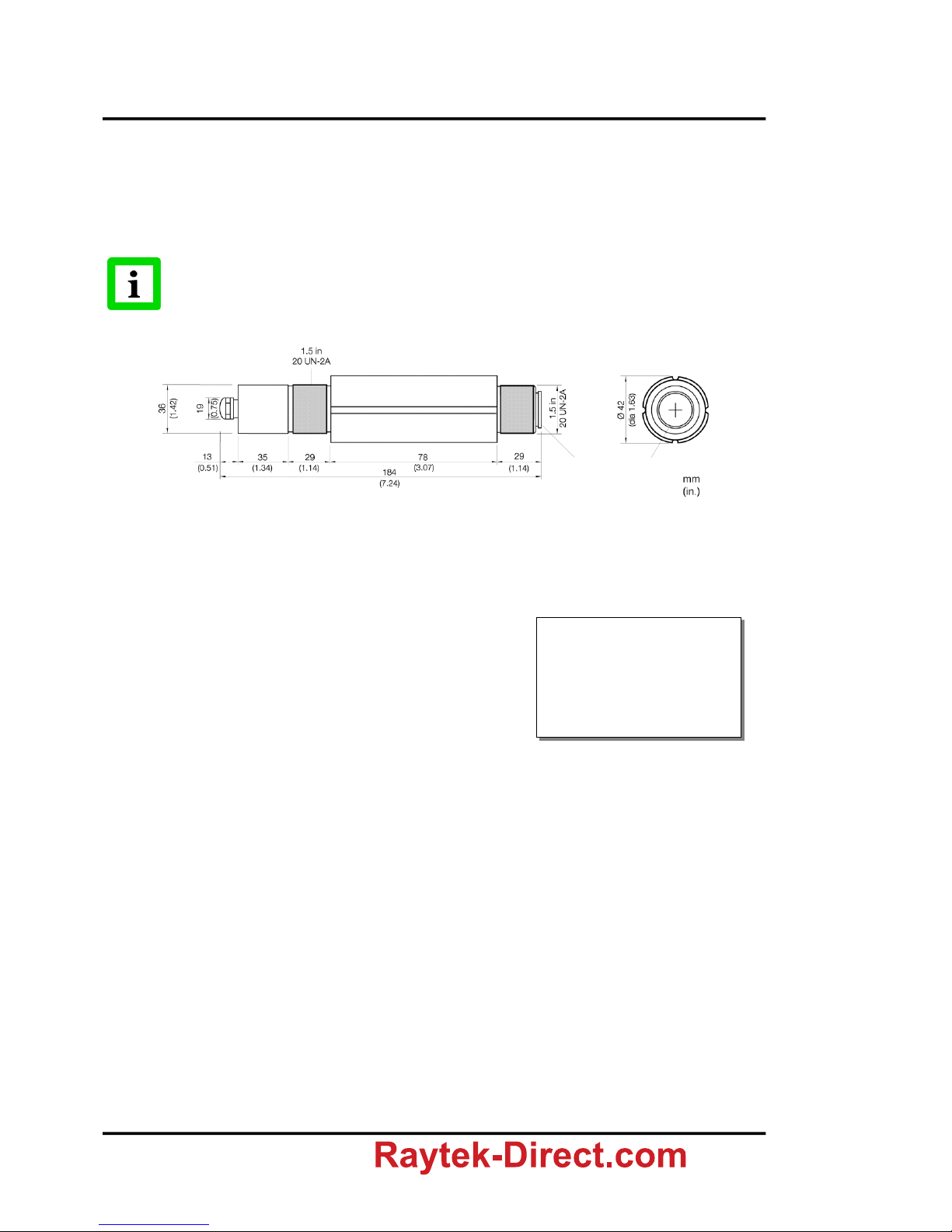
4.2 Dimensions of Sensor
All sensors are supplied with a fixed bracket and mounting nut. Alternatively, the sensor may also be
mounted using customer-supplied accessories. A pipe adapter and other accessories may also be used
(see section 6.1 Overview on page 29).
All sensors and accessories are supplied with 1.5“ 20 UN 2 threads!
Figure 4: Dimensions of the Sensor
4.2.1 Fixed Brackets
Figure 5: Fixed bracket XXXTXXACFB (left) with sensor delivered
4.3 Connecting the Signal Line
Before connecting the cable to the sensor (standard and Smart models) you should unscrew the cap
from the back of the sensor. Proceed as follows:
Protective Window
1.888.610.7664 info@Raytek-Direct.com
Page 14

Installation
TX Rev. O7 07/2017 17
1.) Prepare the cable, remove about 6cm (2.36 in) of
the insulation. Shorten the shield to about 1cm (0.4 in).
Tin-coat the connecting leads.
2.) Unscrew the end-cap until it can be pulled away
from the sensor body.
3.) Open the PG threaded cable gland.
4.) The cable gland consists of a PG nut,
a plastics part and a metal cone ring.
5.) Feed the prepared cable through the components
of the cable gland.
6.) Make sure to have a proper contact between the
braided shield and the metal cone ring.
7.) Place the PG screwed cable gland back into the
outer cap. Tighten the PG nut firmly.
8.) Connect the signal wires to the screw terminals.
9.) Screw the end-cap firmly onto the sensor until it is tight (flush with the sensor body).
IMPORTANT: Neither the end-cap nor the cable gland should have any play after tightening.
1.888.610.7664 info@Raytek-Direct.com
Page 15

Installation
18 Rev. O7 07/2017 TX
The screwed cable gland described above is not a strain relief! Consequently, the cable
must be clamped accordingly during the installation. The outside diameter of the
connecting cables (round cable) should lie between 4 to 6 mm (about 0.2 inches). Note
that it might be necessary to additionally seal the cable entry to allow IP65 with smaller
cables!
1.888.610.7664 info@Raytek-Direct.com
Page 16

Installation
TX Rev. O7 07/2017 19
4.4 Basic Model
The standard model is available for °C or °F. It
provides a 2 pin screw-jumper terminal for
connecting the 4 to 20 mA current loop. The polarity
is indicated on the panel.
Above the screw-jumper terminal there are two
rotary switches for emissivity setting. Emissivity is
preset at the factory at 0.95 (see figure). The appendix
lists typical emissivity values for common materials,
see appendix see section 9.2 Typical Emissivity
Values, page 42.
4.4.1 Installation with a Controller
Figure 7: Typical installation of basic model
4.5 Smart Model
The Smart model has a 3 pin screw-jumper terminal
for connecting the 4 to 20 mA current loop and the
alarm output. The terminal assignment is marked on
the panel. To allow clip leads from a HART adapter to
attach directly to the sensor for setting sensor
parameters, raise the removable terminal strip about
4 mm (0.2 inches) from the rear panel board and
connect across the exposed (+) and (-) pins. For
example, via line terminals, a lap-top with a HART
adapter can be used for programming the sensor.
4.5.1 HART Protocol
Originally, transmission of information was in one direction only, from sensing head to process control.
The parameters monitored for the production of a product were not changed. In order to use the same
technological equipment to manufacture a multitude of differing products, it must be possible to
quickly alter many process parameters. This has an effect on the sensing head. Measuring range,
accuracy and alarm values must be redefined. It would be extremely inconvenient if it were necessary
to reprogram the sensing head at the unit every time. The HART protocol arose from this requirement.
It allows the application of ”intelligent” sensors. The sensing heads can be programmed from the control
room. This means that information is transmitted in two directions. The sensing head provides analog
measured values to the control room via the 4 to 20 mA current loop. The sensing head can be
reprogrammed from the control room by means of bi-directional transmission of digital signals. The
superposition of analog and digital signals is described by the HART protocol. Sensors which are
programmable in this way are called SMART sensors. Apart from the Smart model, a HART/RS232
Figure 8: Back panel of basic model
Figure 6: Back panel of basic model
Controller
Shield
Basic model
1.888.610.7664 info@Raytek-Direct.com
Page 17

Installation
20 Rev. O7 07/2017 TX
adapter is also available. This adapter allows programming of infrared sensing heads using a computer
with an RS232 interface.
4.5.2 HART/RS232 Adapter
The adapter (XXXTXACRCK) allows both remote
setting and signal processing of one or more sensors
in a 4 to 20 mA current loop. A software suitable for a
Windows® PC are supplied together with the adapter.
The adapter has a 25-pin terminal connector for
connecting to an RS232 interface. Screw terminals are
provided for connecting the 4 to 20 mA current loop,
terminal 4 (S2) and terminal 5 (S1).
Terminal 6 is connected internally to computer chassis ground!
4.5.3 Installation of Smart Model
Figure 10: Typical installation of Smart model using the external resistor
Figure 11: Typical installation of Smart model using the internal resistor
Figure 9: HART/RS232 adapter
Controller, Display, or just nothing
within the current loop.
Computer
COM-Port
Controller, Display, or just nothing
within the current loop.
Computer
COM-Port
1.888.610.7664 info@Raytek-Direct.com
Page 18

Installation
TX Rev. O7 07/2017 21
4.5.4 Address Assignment for Multiple Sensors
The sensing heads are factory-programmed with ”Polling Address 0”!
When installing a number of sensors, note that each sensing head must first be assigned a separate
polling (1 to 15). To do this, use the software supplied with the Smart model, and the HART/RS232
adapter:
Install the software, see software manual.
Connect the HART/RS232 adapter to the RS232 interface of your computer.
Connect the Smart model which is to be programmed to the adapter. Use either the installation
with the external resistor or the alternative with the internal resistor.
For configuring the sensor, go to the <Sensor> <Sensor Setup> menu in the software.
Figure 12: Address assignment with external (left) and internal (right) resistor
Sensor
1.888.610.7664 info@Raytek-Direct.com
Page 19

Installation
22 Rev. O7 07/2017 TX
4.5.5 Installation of Multiple Sensors (digital, address mode)
Maximum 15 sensors can be used. The polling address must always be >0.
Communication is purely digital, no analog current output is provided
Set each sensor failsafe mode to “minimum”
Figure 13: All sensors in digital communication using the external resistor
Figure 14: Multiple sensors using the internal resistor
The sensing heads are factory-programmed with ”Polling Address 0”!
When installing a number of sensors, note that each sensing head must first be assigned a separate
polling address (1 to 15), section 4.5.4 Address Assignment for Multiple Sensors on page 21).
POWER SUPPLY
Sensors
Voltage [V]
Op. Current [mA]
1
2
3
4
5
6
7
8
9
10
11
12
13
14
15
24
24
24
24
24
24
24
24
24
24
24
24
28
28
28
4
8
12
16
20
24
28
32
36
40
44
48
52
56
60
Monitor
HART/RS232
Adapter
Shield (6)
Sensor1
Sensor2
Sensor...
!
1.888.610.7664 info@Raytek-Direct.com
Page 20

Installation
TX Rev. O7 07/2017 23
4.5.6 Installation of Multiple Sensors (digital and analog, address mode)
Maximum 12 sensors can be used.
Analog and digital communication for the sensor with polling address 0.
Communication for the remaining 11 sensors purely digital.
Figure 15: All sensors in digital communication, first sensor also with analog current output
The sensing heads are factory-programmed with ”Polling Address 0”!
When installing a number of sensors, note that each sensing head must first be assigned a separate
polling address (0 to 11), section 4.5.4 Address Assignment for Multiple Sensors on page 21).
4.5.7 Installation of Multiple Sensors (digital and analog, tag mode)
To run a sensor with analog current output, the sensor is to address with polling address 0. In case of
having multiple sensors running with analog current output, the polling address can not be the criteria
to distinguish between the sensors, because every sensor would be set to the same address. To avoid
this, a sensor can be named by means of a so called tag. The tag will be stored within the units memory
and can later be used to identify the sensor uniquely.
POWER SUPPLY
Sensors
Voltage [V]
Op. Current [mA]
1
2
3
4
5
6
7
8
9
10
11
12
24
24
24
24
24
24
24
24
28
28
28
28
23
27
31
35
39
43
47
51
55
59
63
67
HART/RS232
Adapter
Monitor
Shield (6)
!
1.888.610.7664 info@Raytek-Direct.com
Page 21

Installation
24 Rev. O7 07/2017 TX
Figure 16: All sensors in digital communication and with analog current output
In case of having more than 3 units, please contact your local dealer for additional
information for installing!
To prepare sensors for tag mode:
1. The sensing heads are factory-programmed with ”Polling Address 0”.
2. Start up the software with a single sensor (address mode).
3. Define a unique tag for the sensor, see the <Advanced Setup> in the menu <Sensor> <Sensor
Setup>.
4. Exit the software.
5. Repeat steps 2 to 4 for every additional sensor.
6. Start up the software with multiple sensors, select <Define Scan List>, input the tags for all
requested sensors.
4.5.8 Alarm Output
The alarm output of the Smart model is not electrically
isolated. The maximum current carrying capacity is 150
mA. Use the circuit diagram. The LED is operated with
10 mA and could be used as an indicator, or as an
optocoupler. The alarm current does not influence the
signal current (4 to 20 mA current loop).
Figure 17: Using the alarm output
HART/RS232
Adapter
Monitor
Shield (6)
current loop
1.888.610.7664 info@Raytek-Direct.com
Page 22

Options
TX Rev. O7 07/2017 25
5 Options
A full range of options for various applications and environments are available. Options are factoryinstalled and must be specified at the time of placing the order:
°C or °F (basic model only)
Air/Water cooled housing (Option: …W), includes air purge
Intrinsically-safe rating
…IS4 for TXS models
…IS4W for TXS models with Air/Water-Cooled Housing
…IS5 for TXS models in stainless steel
…IS5W for TXS models in stainless steel and Air/Water-Cooled Housing
ISO Calibration Certificate, based on national standards (e.g. DAkkS) (XXXTXCERT)
Sensor in stainless steel (…S)
5.1 Air/Water-Cooled Housing
The Air/Water-Cooled Housing option allows the sensor to be used in ambient temperatures up to
120°C (250°F) with air-cooling, and 175°C (350°F) with water-cooling. The cooling media should be
connected using 1/8” NPT stainless steel fittings. Air flow should be 1.4 to 2.5 l/sec at 25°C (77°F). Water
flow should be approximately 1.0 to 2.0 l/min (water temperature between 10 and 27°C (50 to 80.6°F).
Chilled water below 10°C (50°F) is not recommended, see section 5.1.2 Avoidance of Condensation on
page 26.
The Air/Water-Cooled Housing is also available in stainless steel (…S).
Figure 18: Sensor with Air/Water-Cooled Housing
Stainless Steel Fittings
1.888.610.7664 info@Raytek-Direct.com
Page 23

Options
26 Rev. O7 07/2017 TX
5.1.1 Connecting
As a standard the cooled housing is supplied with fittings and non-metric 1/8” NPT threads. If you
intend to supply the cooling media through pipes or hoses, consider the following information.
Thread Adapter - metric pipe to NPT inside thread
Thread Adapter - inch-type pipe to NPT inside thread
Supporting tube for PVC or Tygon hoses
5.1.2 Avoidance of Condensation
If environmental condition makes water cooling necessary, it is strictly recommended to check whether
condensation will be a real problem or not.
Water cooling also causes a cooling of the air in the inner part of the device. Thereby the capability of
the air to store water decreases. The relative humidity increases and can reach 100% very quickly. In
case of a further cooling, the surplus water steam will come out as water (condensation). The water will
condense on the lenses and the electronics resulting in possible damage to the sensor. Condensation can
even happen on an IP65 sealed housing.
There is no warranty repair possible in case of condensed water within the housing!
To avoid condensation, the temperature of the cooling media and the flow rate have to ensure a
minimum device temperature. The minimum device temperature depends on the ambient temperature
and the relative humidity, please consider the following table.
Inner Thread NPT (in.)
Pipe Outer Ø
1/8
4 mm (0.16 in)
1/8
6 mm (0.24 in)
1/8
8 mm (0.31 in)
Inner Thread NPT (in.)
DIN-ISO-Outer Thread
1/8
4 mm (0.16 in)
Tuber Outer Ø
Tube Inner Ø
6 mm
4 mm
8 mm
6 mm
1.888.610.7664 info@Raytek-Direct.com
Page 24

Options
TX Rev. O7 07/2017 27
Relative Humidity [%]
Ambient Temperature [°C/°F]
10
15
20
25
30
35
40
45
50
55
60
65
70
75
80
85
90
95
100
0/
32
0/
32
0/
32
0/
32
0/
32
0/
32
0/
32
0/
32
0/
32
0/
32
0/
32
0/
32
0/
32
0/
32
0/
32
0/
32
0/
32
0/
32
0/
32
0/
32
5/
41
0/
32
0/
32
0/
32
0/
32
0/
32
0/
32
0/
32
0/
32
0/
32
0/
32
0/
32
0/
32
0/
32
0/
32
0/
32
0/
32
0/
32
0/
32
5/
41
10/
50
0/
32
0/
32
0/
32
0/
32
0/
32
0/
32
0/
32
0/
32
0/
32
0/
32
0/
32
0/
32
0/
32
5/
41
5/
41
5/
41
5/
41
5/
41
10/
50
15/
59
0/
32
0/
32
0/
32
0/
32
0/
32
0/
32
0/
32
0/
32
0/
32
5/
41
5/
41
5/
41
5/
41
10/
50
10/
50
10/
50
10/
50
10/
50
15/
59
20/
68
0/
32
0/
32
0/
32
0/
32
0/
32
0/
32
5/
41
5/
41
5/
41
10/
50
10/
50
10/
50
10/
50
15/
59
15/
59
15/
59
15/
59
15/
59
20/
68
25/
77
0/
32
0/
32
0/
32
0/
32
5/
41
5/
41
10/
50
10/
50
10/
50
10/
50
15/
59
15/
59
15/
59
20/
68
20/
68
20/
68
20/
68
20/
68
25/
77
30/
86
0/
32
0/
32
0/
32
5/
41
5/
41
10/
50
10/
50
15/
59
15/
59
15/
59
20/
68
20/
68
20/
68
20/
68
25/
77
25/
77
25/
77
25/
77
30/
86
35/
95
0/
32
0/
32
5/
41
10/
50
10/
50
15/
59
15/
59
20/
68
20/
68
20/
68
25/
77
25/
77
25/
77
25/
77
30/
86
30/
86
30/
86
30/
86
35/
95
40/
104
0/
32
5/
41
10/
50
10/
50
15/
59
20/
68
20/
68
20/
68
25/
77
25/
77
25/
77
30/
86
30/
86
30/
86
35/
95
35/
95
35/
95
35/
95
40/
104
45/
113
0/
32
10/
50
15/
59
15/
59
20/
68
25/
77
25/
77
25/
77
30/
86
30/
86
35/
95
35/
95
35/
95
35/
95
40/
104
40/
104
40/
104
40/
104
45/
113
50/
122
5/
41
10/
50
15/
59
20/
68
25/
77
25/
77
30/
86
30/
86
35/
95
35/
95
35/
95
40/
104
40/
104
40/
104
45/
113
45/
113
45/
113
45/
113
50/
122
60/
140
15/
59
20/
68
25/
77
30/
86
30/
86
35/
95
40/
104
40/
104
40/
104
45/
113
45/
113
50/
122
50/
122
50/
122
50/
122
50/
122
50/
122
50/
122
60/
140
70/
158
20/
68
25/
77
35/
95
35/
95
40/
104
45/
113
45/
113
50/
122
50/
122
50/
122
50/
122
50/
122
60/
140
60/
140
60/
140
60/
140
60/
140
60/
140
70/
158
80/
176
25/
77
35/
95
40/
104
45/
113
50/
122
50/
122
50/
122
60/
140
60/
140
60/
140
60/
140
60/
140
70/
158
70/
158
70/
158
70/
158
70/
158
70/
158
80/
176
90/
194
35/
95
40/
104
50/
122
50/
122
50/
122
60/
140
60/
140
60/
140
70/
158
70/
158
70/
158
70/
158
80/
176
80/
176
80/
176
80/
176
80/
176
80/
176
90/
194
100/
212
40/
104
50/
122
50/
122
60/
140
60/
140
70/
158
70/
158
70/
158
80/
176
80/
176
80/
176
80/
176
80/
176
90/
194
90/
194
90/
194
90/
194
90/
194
100/
212
Tab. 1: Minimum device temperatures [°C/°F]
Temperatures higher than 60°C /
140°F are not recommended due to
the temperature limitation of the
device.
Example:
Ambient temperature = 50 °C
Relative humidity = 40 %
Minimum device temperature = 30 °C
The use of lower temperatures is at your own risk!
1.888.610.7664 info@Raytek-Direct.com
Page 25

Options
28 Rev. O7 07/2017 TX
5.2 ATEX Intrinsic Safety
The Smart unit is available with Intrinsic Safety rated as:
II 2G Ex ib IIC T4 Gb for -20°C < TAmbient < 70°C (-4°F < TAmbient < 158°F)
II 2D Ex ib IIIC T135°C Db IP65 for -20°C < TAmbient < 70°C (-4°F < TAmbient < 158°F)
The required power supply barrier for the unit must be ordered separately.
This intrinsically safe unit is available with a water-cooled housing. The water cooled housing can
provide a cooler, more stable operating environment for the electronics but does not allow for approved
IS operation when external ambient conditions are above 70°C (158°F).
The recommended power supply barrier for the unit consists, in its simplest form, of two parts from the
CONTRANS I series, manufactured by ABB Automation (formerly Hartmann & Braun):
XXXAOIS2 – Intrinsically Safe isolating Driver, Part # V17151-620
Din Rail mounted Sockets:
XXXAOIS1 – socket for one driver, with integrated power supply for input voltages of 95 to
253 VAC (V17111-130)
XXXAOIS6 – socket for one driver, with integrated power supply for input voltages of 19 to
33 VDC (V17111-120)
XXXAOIS3 – socket for up to eight drivers (V17111-251)
XXXAOIS4 – socket for up to 16 drivers (V17111-351)
The CONTRANS I interface modules are a series of driver modules, power supplies, and backplanes,
all of which can be intermixed to provide the best solution for a specific application. The recommended
solution, consisting of a single intrinsically safe isolating module and a single power supply socket, is
only one of several combinations possible.
Figure 19: Intrinsic Safety Installation (example)
Units with Intrinsic Safety (IS) rating are also available made from stainless steel.
The metallic enclosure of the intrinsically safe unit is not earthed by installation. At
least one of the following safety measures must be met to minimize the danger of
electrostatic charges:
Earth grounding of the cable shield
Installing the unit’s metallic enclosure on an earth grounded mounting bracket
or on any other grounded bases
Please also consider section 9.4 ATEX Certificate of Conformity, page 47.
Socket
HART
Adapter
Power
Explosion critical area
Isolating Driver
Ui = 22 V
Ii = 30 mA
Pi = 660 mW
Li = 0,17 mH
Ci = 16 nF
1.888.610.7664 info@Raytek-Direct.com
Page 26

Accessories
TX Rev. O7 07/2017 29
6 Accessories
6.1 Overview
For all models:
Mounting Nut XXXTXXACMN
Fixed Mounting Bracket XXXTXXACFB
Adjustable Bracket XXXTXXACAB
Air Purge Collar XXXTXXACAP
Right Angle Mirror XXXTXXACRA
Sighting Viewer XXXTXXACSV
Pipe Adapter XXXTXXACPA
Pipe Adapter XXXTXXAPA
ThermoJacket Housing RAYTXXTJ3M
Industrial Power Supply XXXSYSPS
Protective Window for lens protection
Panel Mount Display RAYGPC/RAYGPCM
For Smart model:
PC communications software, HART/RS232 Adapter XXXTXACRCK
USB/RS232 Adapter XXXUSB485S
Figure 20: Overview to the available accessories
Adjustable Pipe Adapter
(XXXTXXAPA)
Sighting Viewer
(XXXTXXACSV)
Right Angle Mirror
(XXXTXXACRA)
Air Purge Collar
(XXXTXXACAP)
Mounting Nut
(XXXTXXACMN)
Sensor
Fixed Bracket
(XXXTXXACFB)
Adjustable Bracket
(XXXTXXACAB)
Sensor with Air-/Water Cooled
Housing (Option)
ThermoJacket and Accessories
(RAYTXXTJ3M)
1.888.610.7664 info@Raytek-Direct.com
Page 27

Accessories
30 Rev. O7 07/2017 TX
6.2 Adjustable Bracket
Figure 21: Adjustable Bracket (XXXTXXACAB)
6.3 Air Purge Collar
The Air Purge Collar (XXXTXXACAP) is used to keep dust, moisture, airborne particles, and vapors
away from the lens. It can be mounted before or after the bracket. The air flow is passed through 1/8”
NPT stainless steel fitting onto the front aperture. Air flow should be a maximum of 0.5 to 1.5 l/sec.
Clean, oil free air is recommended.
Figure 22: Dimension of Air Purge Collar (left), Sensor with Air Purge Collar (right)
6.4 Right Angle Mirror
The Right Angle Mirror (XXXTXXACRA) is used to turn the field of view by 90° against the sensor axis.
It is recommended when space limitations or excessive radiation do not allow to directly align the sensor
to the target. The mirror must be installed after the bracket and after the Air Purge Collar and screwed
in fully. In dusty or contaminated environments, air purging is required to keep the mirror surface
clean.
1.888.610.7664 info@Raytek-Direct.com
Page 28

Accessories
TX Rev. O7 07/2017 31
Figure 23: Right Angle Mirror
When using the Right Angle Mirror, adjust the emissivity settings downward by 5%.
For example, for an object with an emissivity of 0.65, you adjust the value down to 0.62.
This correction accounts for energy losses in the mirror!
6.5 Sighting Viewer
The Sighting Viewer (XXXTXXACSV) is used to aid in the alignment of the standard sensor. It is used
when the object is small and far from the sensor as well as when it is difficult to obtain a direct in-line
sighting. It can be used both with and without the Air Purge Collar, but not with the Right Angle Mirror.
First secure the sensor to the bracket using the mounting nut or the Air Purge Collar. Next screw on the
Sighting Viewer Tool fully. Now, position and secure the bracket. When the alignment is complete, do
not forget to remove the Sighting Viewer Tool.
Figure 24: Sighting Viewer
6.6 Pipe Adapter
The adjustable pipe adapter (XXXTXXACPA) is available to connect a sighting tube or conduit to a
sensor with or without water/air cooled housing.
1.888.610.7664 info@Raytek-Direct.com
Page 29

Accessories
32 Rev. O7 07/2017 TX
Figure 25: Pipe Adapter
6.7 Adjustable Pipe Adapter
The adjustable pipe adapter accessory (XXXTXXAPA) can be permanently placed on a surface and
aimed in any direction within a 45° radius. The accessory kit includes two mounting flanges, a circular
pipe adapter, a 2” pipe nipple, a mounting flange for sighting tube, and all necessary bolts and washers.
Figure 26: Adjustable Pipe Adapter
6.8 ThermoJacket
The ThermoJacket® allows use of the sensor in ambient temperatures up to 315°C (600°F). The rugged
cast aluminum housing completely encloses the sensor and provides water cooling as well as air
purging. Sensing heads can easily be installed or removed with the ThermoJacket housing in its
mounted position.
2x Mounting flange
(XXXTXXMF)
Mounting flange for
sighting tube (XXXTXXMST)
1.888.610.7664 info@Raytek-Direct.com
Page 30

Accessories
TX Rev. O7 07/2017 33
Figure 27: ThermoJacket (RAYTXXTJ3)
For more information see the ThermoJacket’s manual.
1.888.610.7664 info@Raytek-Direct.com
Page 31

Accessories
34 Rev. O7 07/2017 TX
6.9 Industrial Power Supply
The DIN-rail mount industrial power supply delivers isolated dc power and provides short circuit and
overload protection.
To prevent electrical shocks, the power supply must be used in protected environments
(cabinets)!
Technical data:
Protection class prepared for class II equipment
Environmental protection IP20
Operating temperature range -25°C to 55°C (-13°F to 131°F)
AC Input 100 – 240 VAC 44/66 Hz
DC Output 24 VDC / 1.3 A
Cross sections input/output
0.08 to 2.5 mm² (AWG 28 to 12)
1
Figure 28: Industrial Power Supply (XXXSYSPS)
1
Copyright Wago®
1.888.610.7664 info@Raytek-Direct.com
Page 32

Accessories
TX Rev. O7 07/2017 35
6.10 Protective Window
Protective windows can be used to protect the sensor’s optic against dust and other contaminations. For
sensors with plastic lenses the use of a protective window combined with the air purge is strongly
recommended.
The following table provides an overview of the available protective windows recommended for a LT,
MT, HT, G5 and P7 model. All protective windows are also available in stainless steel (…S).
Order number
Model
Designation
Material
XXXTXACTWL
LT
none
Amtir
0.65
0.05
XXXTXACTWLF1
LT
none (stainless steel)
Polyethylene foil
(non-poisonous, non-fragile)
0.75
0.05
XXXTXACTWM
MT
4 red dots
Sapphire
0.88
0.05
XXXTXACTWH
HT
3 red dots
Glass
0.88
0.05
XXXTXACTWGP
G5, P7
2 red dots
Calcium Fluorid
0.93
0.05
Table 2: Protective Windows
For special requirements, please ask our Sales Department about our range of special protective
windows.
Models delivered with mounted protective windows are preset as follows:
Basic model Basic model has no adjustable parameter for the transmissivity. The influence of
transmissivity is reflected by a resulting emissivity value. E.g. transmissivity of
protective window is 0.88, emissivity of measured object is 0.95, resulting emissivity
value is set with the two rotary switches to 0.84 (0.88 * 0.95 = 0.84)
Smart model Transmissivity for the protective window is set in the software directly. The emissivity
value is not changed.
Determination of transmissivity of an unknown protective window:
If transmissivity of the measuring screen is not indicated on the data sheet, you can also determine the
transmissivity yourself. Please proceed as follows:
1. Measure the temperature of the target object with the sensing head, without using the protective
window. Note correct setting of emissivity. With the basic model, emissivity is set with the two
rotary switches. For the Smart model, the emissivity is entered in the software and the value for
“Transmissivity“ is specified as 1.00.
2. Insert the protective window in the sensing head.
3. If you use the basic model of the sensing head, adjust the emissivity until the same temperature is
displayed, as was determined without the protective window.
If the smart model is used, adjust the transmissivity in the software until the same temperature is
displayed, as it was determined without the protective window.
For more information regarding the mounting of a protective window, see section 8.4 Replacing a
Protective Window on page 40.
1.888.610.7664 info@Raytek-Direct.com
Page 33

Accessories
36 Rev. O7 07/2017 TX
6.11 USB/RS232 Adapter
The USB/RS232 Adapter is one standard USB 2.0 to serial bridge that has one DB-9 RS232 male
connector. The DB-9 pin serial port is configured as a DTE (data terminal equipment) device which is
same as all PC COM ports. The industry DIN rail and panel mounting design enable user a fast and
professional installation.
Technical Data
Power supply 5 VDC direct from USB port
Speed max. 256 kBit/s
RS232 standard 9 pin DTE full-duplex
USB connector type B (supplied with type A to type B cable)
Ambient Temperature 0 to 60°C (32 to 140°F), 10-90% relative humidity, non-condensing
Storage Temperature -20 to 70°C (-4 to 158°F), 10-90% relative humidity, non-condensing
Dimensions (L x W x H) 151 x 75 x 26 mm (5.9 x 2.9 x 1 in)
Figure 29: USB/RS232 Converter (XXXUSB485S)
TX Sensor HART/RS232 Adapter RS232/USB Adapter Computer
Figure 30: Principal bridging a TX sensor with HART communication
via RS232 to USB communications
1.888.610.7664 info@Raytek-Direct.com
Page 34

Software
TX Rev. O7 07/2017 37
7 Software
7.1 Requirements
PC running Windows 2000/XP/Vista/Win7 at minimum 64 MB RAM
approx. 10 MB hard-disc memory for the program
7.2 Installation and Start
The following explains how to start and setup the software. Make sure any sensor or sensors are turned
on before running the program. The Startup Wizard runs the first time you use the program. After the
first saving your settings, the program starts at the Main screen.
Software Start
1. To install the software, choose the SETUP.EXE file on your data medium.
2. Double click the <DataTemp Multidrop> icon on your desktop to open the software. The
software prompts you to choose to create a new file or open a saved file. Click the <Create a
New File> button.
3. The software checks for a free COM port, this appears as pre-setting. Make sure the <HART
Protocol> is selected on the screen.
4. Click <Continue> and follow instructions on the screen.
5. On the last screen click <Finish>.
Figure 31: Setting the Software to <HART> Protocol
After communication with the devices (real or simulated) is established, a screen similar to the one
below displays. This screen shows how many devices are attached as well as their identification
numbers and types of devices. Check here to make sure all installed devices are connected properly.
Note: If you notice that not all devices were found, click on the <Back> button to return to the previous screen,
then go check your sensor connections. After checking, click on the <Continue> button so the software
rescans for connected devices.
1.888.610.7664 info@Raytek-Direct.com
Page 35

Software
38 Rev. O7 07/2017 TX
Figure 32: List of Found Devices
7.3 Sensor Setup
Selecting <Sensor Setup> from the <Setup> displays a list of attached sensors. When you select one, a
screen similar to the following displays.
In the <Sensor Setup> screen, you may configure the settings for the signal processing (emissivity,
ambient control, hold modes, fail safe mode), the output signals (alarms and relay), and the advanced
setup (polling address, descriptions).
Figure 33: <Sensor Setup> Menu
See the DataTemp Multidrop software help for further instructions!
1.888.610.7664 info@Raytek-Direct.com
Page 36

Maintenance
TX Rev. O7 07/2017 39
8 Maintenance
Our customer service representatives are always at your disposal for any questions you might have.
This service includes any support regarding the proper application of your infrared measuring system,
calibration or the solution to customer-specific solutions as well as repair.
In many cases your problems will be applications-specific and can possibly be solved over the
telephone. So, if you need to return equipment to us, please contact our Service Department before
doing so, see phone and fax numbers at the beginning of this document.
8.1 Troubleshooting Minor Problems
Symptom
Possible Cause
Solution
No Output
Erroneous Temperature
Erroneous Temperature
Erroneous Temperature
Erroneous Temperature
Temperature Fluctuates
Cable Disconnected
Faulty Sensor Cable
Field of View Obstructed
Lens Dirty
Wrong Emissivity Setting
Wrong Signal Processing
Check Cable Connections
Verify Cable's Integrity
Remove the Obstruction
Clean the Lens
Correct the Setting
Correct Peak, Valley, or Average Settings
Tab. 3: Troubleshooting
8.2 Automatic Error Indication
The automatic error indication (alarm output) shall warn the user and guarantee a secure output in the
event of a system error. In the first place, however, its task is to switch the system off in case of a faulty
setup or a defect in the sensing head or in the electronic circuits.
Please select the desired Alarm Mode, see <Advanced Setup> in the menu <Sensor> <Sensor Setup> of
the software.
Off no alarm function
Normally Open open output within the alarm thresholds
Normally Closed closed output within the alarm thresholds
Intern. Temp. n.c. open, if internal sensor temperature is exceeded
Intern. Temp. n.o. closed if internal sensor temperature is exceeded
Current output:
Symptom
4 – 20 mA Output
Internal defect
21 mA
Target temperature under range
4 mA
Target temperature over range
20 mA
Never rely exclusively on the automatic error indication when monitoring critical
heating processes. It is strongly recommended to take additional safety measures!
1.888.610.7664 info@Raytek-Direct.com
Page 37

Maintenance
40 Rev. O7 07/2017 TX
8.3 Cleaning the Lens
Care should be taken to keep the lens clean. Any foreign matter on the lens will affect the accuracy of
the measurements. Be sure to take care when cleaning the lens. Please observe the following:
1. Blow off lose particles with clean air.
2. Gently brush off remaining particles with a soft camel hair brush.
3. To remove any more severe contamination use a clean, soft cloth dampened with distilled
water. In any case, do not scratch the lens surface!
For finger prints or other grease, use any of the following:
Denaturated alcohol
Ethanol
Kodak lens cleaner
Apply any of the above to the lens. Wipe gently with a clean, soft cloth until you see colors on the lens
surface, then allow to air dry. Never wipe the surface dry, this may scratch the surface. If the lens is
contaminated with silicones (e.g. from hand creams), clean it carefully using Hexane. Allow the lens to
air dry.
Do not use any ammonia or any cleaners containing ammonia to clean the lens.
This may result in permanent damage to the lens’ surface!
8.4 Replacing a Protective Window
8.4.1 Models produced after May 1999
Attention! Beginning production date May 1999, the models contain a thread allowing an easier
protective window exchange. (If you received your model together with this manual, your model was
produced after May 1999.) If you own an older model, refer to the description given in section 8.4.2
Models produced before May 1999 on page 41.
Make sure to use the appropriate protective window for the spectral range of your sensor model, for
more information see section 6.10 Protective Window on page 35.
The window material is placed in a metal ring with a thread with an inner rubber gasket. This rubber
gasket hermetically seals the sensor against atmospheric contaminants.
Replace the protective window using the special tool supplied with the spare window. Put the tools
nozzles into the wholes on the window’s mounting ring. Now gently unscrew the protective window
from its mount by turning to the left. Take care to screw in the new protective window as tight as
possible, but do not over tighten!
1.888.610.7664 info@Raytek-Direct.com
Page 38

Maintenance
TX Rev. O7 07/2017 41
Figure 34: Replacing the Protective Window
8.4.2 Models produced before May 1999
Attention! If you own a model produced before May 1999 and where the protective window looks
similar to the one shown on the photographs below, refer to the following description.
Make sure to use the appropriate protective window for the spectral range of your sensor model, for
more information see section 6.10 Protective Window on page 35.
The window material is placed in a metal ring which is enclosed with a rubber gasket. This rubber
gasket keeps the protective window in the sensor. (Models produced later than May 1999 have a thread
instead - check this, before you order spare parts!)
Replace the protective window using the plastic levers supplied with the spare window. Place the
levers’ blades beneath the projection of the protective window. Now gently lever the protective window
from its mount.
Figure 35: Replacing the Protective Window
Sensor
Window
Mounting Tool
1.888.610.7664 info@Raytek-Direct.com
Page 39

Appendix
42 Rev. O7 07/2017 TX
9 Appendix
9.1 Determination of Emissivity
Emissivity is a measure of an object’s ability to absorb and emit infrared energy. It can have a value
between 0 and 1.0. For example a mirror has an emissivity of 0.1, while the so-called “Blackbody“
reaches an emissivity value of 1.0. If a higher than actual emissivity value is set, the output will read
low, provided the target temperature is above its ambient temperature. For example, if you have set
0.95 and the actual emissivity is 0.9, the temperature reading will be lower than the true temperature.
An object’s emissivity can be determined by one of the following methods:
1. Determine the actual temperature of the material using an RTD (PT100), a thermocouple, or any
other suitable method. Next, measure the object’s temperature and adjust emissivity setting until
the correct temperature value is reached. This is the correct emissivity for the measured material.
2. For relatively low temperatures (up to 260°C / 500°F) place a plastic sticker (e.g. XXXRPMACED)
on the object to be measured. This sticker should be large enough to cover the target spot. Next,
measure the sticker’s temperature using an emissivity setting of 0.95. Finally, measure the
temperature of an adjacent area on the object and adjust the emissivity setting until the same
temperature is reached. This is the correct emissivity for the measured material.
3. If possible, apply flat black paint to a portion of the surface of the object. The emissivity of the paint
must be above 0.98. Next, measure the temperature of the painted area using an emissivity setting
of 0.98. Finally, measure the temperature of an adjacent area on the object and adjust the emissivity
until the same temperature is reached. This is the correct emissivity for the measured material.
To optimize surface temperature measurements, consider the following guidelines:
Determine the object emissivity using the instrument which is also to be used for the
measurements.
Avoid reflections by shielding the object from surrounding temperature sources.
For higher temperature objects use instruments with the shortest wavelength possible.
For translucent materials such as plastic foils or glass, assure that the background is uniform
and lower in temperature than the object.
Mount instrument perpendicular to surface if possible. In all cases, do not exceed angles more
than 30° from incidence.
9.2 Typical Emissivity Values
The following table provides a brief reference guide for determining emissivity and can be used when
one of the above methods is not practical. Emissivity values shown in the table are only approximate,
since several parameters may affect the emissivity of a material. These include the following:
1. Temperature
2. Angle of measurement
3. Geometry (plane, concave, convex)
4. Thickness
5. Surface quality (polished, rough, oxidized, sandblasted)
6. Spectral range of measurement
7. Transmissivity (e.g. thin films plastics)
1.888.610.7664 info@Raytek-Direct.com
Page 40

Appendix
TX Rev. O7 07/2017 43
METALS
Material
Emissivity
1 µm
2.2 µm
5.1 µm
8 – 14 µm
Aluminum
Unoxidized
0.1-0.2
0.02-0.2
0.02-0.2
0.02-0.1
Oxidized
0.4
0.2-0.4
0.2-0.4
0.2-0.4
Alloy A3003, Oxidized
0.4
0.4
0.3
Roughened
0.2-0.8
0.2-0.6
0.1-0.4
0.1-0.3
Polished
0.1-0.2
0.02-0.1
0.02-0.1
0.02-0.1
Brass
Polished
0.35
0.01-0.05
0.01-0.05
0.01-0.05
Burnished
0.65
0.4
0.3
0.3
Oxidized
0.6
0.5
0.5
Chromium
0.4
0.05-0.3
0.03-0.3
0.02-0.2
Copper
Polished
0.05
0.03
0.03
0.03
Roughened
0.05-0.2
0.05-0.2
0.05-0.15
0.05-0.1
Oxidized
0.2-0.8
0.7-0.9
0.5-0.8
0.4-0.8
Gold
0.3
0.01-0.1
0.01-0.1
0.01-0.1
Haynes
Alloy
0.5-0.9
0.6-0.9
0.3-0.8
0.3-0.8
Inconel
Oxidized
0.4-0.9
0.6-0.9
0.6-0.9
0.7-0.95
Sandblasted
0.3-0.4
0.3-0.6
0.3-0.6
0.3-0.6
Electropolished
0.2-0.5
0.25
0.15
0.15
Iron
Oxidized
0.7-0.9
0.7-0.9
0.6-0.9
0.5-0.9
Unoxidized
0.35
0.1-0.3
0.05-0.25
0.05-0.2
Rusted
0.6-0.9
0.5-0.8
0.5-0.7
Molten
0.35
0.4-0.6
—
—
Iron, Cast
Oxidized
0.9
0.7-0.95
0.65-0.95
0.6-0.95
Unoxidized
0.35
0.3
0.25
0.2
Molten
0.35
0.3-0.4
0.2-0.3
0.2-0.3
Iron, Wrought
Dull
0.95
0.9
0.9
Tab. 4: Typical Emissivity Values
1.888.610.7664 info@Raytek-Direct.com
Page 41

Appendix
44 Rev. O7 07/2017 TX
METALS
Material
Emissivity
1 µm
2.2 µm
5.1 µm
8 – 14 µm
Lead
Polished
0.05-0.2
0.05-0.2
0.05-0.1
Rough
0.5
0.4
0.4
Oxidized
0.3-0.7
0.2-0.7
0.2-0.6
Magnesium
0.3-0.8
0.05-0.2
0.03-0.15
0.02-0.1
Mercury
0.05-0.15
0.05-0.15
0.05-0.15
Molybdenum
Oxidized
0.5-0.9
0.4-0.9
0.3-0.7
0.2-0.6
Unoxidized
0.25-0.35
0.1-0.3
0.1-0.15
0.1
Monel (Ni-Cu)
0.3
0.2-0.6
0.1-0.5
0.1-0.14
Nickel
Oxidized
0.8-0.9
0.4-0.7
0.3-0.6
0.2-0.5
Electrolytic
0.2-0.4
0.1-0.2
0.1-0.15
0.05-0.15
Platinum
Black
0.95
0.9
0.9
Silver
0.04
0.02
0.02
0.02
Steel
Cold-Rolled
0.8-0.9
—
0.8-0.9
0.7-0.9
Ground Sheet
0.6-0.7
0.5-0.7
0.4-0.6
Polished Sheet
0.35
0.2
0.1
0.1
Molten
0.35
0.25-0.4
0.1-0.2 — Oxidized
0.8-0.9
0.8-0.9
0.7-0.9
0.7-0.9
Stainless
0.35
0.2-0.9
0.15-0.8
0.1-0.8
Tin (Unoxidized)
0.25
0.1-0.3
0.05
0.05
Titanium
Polished
0.5-0.75
0.2-0.5
0.1-0.3
0.05-0.2
Oxidized
0.6-0.8
0.5-0.7
0.5-0.6
Tungsten
0.1-0.6
0.05-0.5
0.03
Polished
0.1-0.3
0.05-0.25
0.03-0.1
Zinc
Oxidized
0.6
0.15
0.1
0.1
Polished
0.5
0.05
0.03
0.02
Tab. 5: Typical Emissivity Values
1.888.610.7664 info@Raytek-Direct.com
Page 42

Appendix
TX Rev. O7 07/2017 45
NON-METALS
Material
Emissivity
1 µm
2.2 µm
5.1 µm
8 – 14 µm
Asbestos
0.9
0.8
0.9
0.95
Asphalt
— 0.95
0.95
Basalt
— 0.7
0.7
Carbon
Unoxidized
0.8-0.9
0.8-0.9
0.8-0.9
Graphite
0.8-0.9
0.7-0.9
0.7-0.8
Carborundum
0.95
0.9
0.9
Ceramic
0.4
0.8-0.95
0.8-0.95
0.95
Clay
0.8-0.95
0.85-0.95
0.95
Concrete
0.65
0.9
0.9
0.95
Cloth
— 0.95
0.95
Glass
Plate
0.2
0.98
0.85
“Gob”
0.4-0.9
0.9 — Gravel
— 0.95
0.95
Gypsum
— 0.4-0.97
0.8-0.95
Ice — — 0.98
Limestone
— 0.4-0.98
0.98
Paint (non-al.)
— —
0.9-0.95
Paper (any color)
— 0.95
0.95
Plastic (opaque, over 20 mils)
— 0.95
0.95
Rubber
— 0.9
0.95
Sand
— 0.9
0.9
Snow
— —
0.9
Soil — — 0.9-0.98
Water
— —
0.93
Wood, Natural
— 0.9-0.95
0.9-0.95
Tab. 6: Typical Emissivity Values
1.888.610.7664 info@Raytek-Direct.com
Page 43

Appendix
46 Rev. O7 07/2017 TX
9.3 Display Monitor
The Display Monitor GP (order number: RAYGPC/RAYGPCM) may be
operated both with the standard and with the Smart model. The monitor
allows Peak Hold, Valley Hold and Average and allows to adjust two
setpoints for alarm- or control use. The display monitor requires a supply
voltage of 110 VAC or 220 VAC. The monitor meets IP54 (IEC529, NEMA-
12) requirements. The unit withstands ambient temperatures in between 0
to 50°C (32 to 120°F). The 1/8 DIN monitor provides a 4 to 20 mA signal
input. The 4 digit LED display has a display resolution from 1°C (1°F). For
more detailed information, please be referred to the GP manual.
9.3.1 Installation with the Sensor
Figure 37: Sensor in analog communication, display with the monitor
The monitor can also be used to provide the power supply for a smart sensor in digital communication
(pin 9: + 24 VDC, pin 10: ground). For activating the 4 – 20 mA current input, the monitor must be set to
the device type H005, see the operating instructions for the monitor.
A possible installation is given in the figure below. For other installations see the figures in section 4.5
Smart Model on page 19.
Figure 38: Sensor in digital communication, display and power with the monitor
Monitor Terminal Block
Shield
Sensor
Computer
COM-Port
Monitor
Sensor
Figure 36: Monitor GP
1.888.610.7664 info@Raytek-Direct.com
 Loading...