

Page 1

Raynger® Series
3i Plus
Handheld Infrared Thermometer
Operating Instructions
Rev. A1 Jan 2015
4557194
Find Quality Products Online at: sales@GlobalTestSupply.com
www.GlobalTestSupply.com
Page 2

Worldwide Headquarters
solutions@raytek.com
European Headquarters
raytek@raytek.de
France
United Kingdom
Fluke Service Center
info@raytek.com.cn
© Raytek Corporation
Raytek
All rights reserved. Specifications
Santa Cruz, CA USA
Tel: +1 800 227 – 8074
+1 831 458 – 3900
Fax: +1 831 458 – 1239
Contacts
(USA and Canada only)
Berlin, Germany
Tel: +49 30 4 78 00 80
Beijing, China
Tel: +86 10 6438 4691
Tel: +86 10 4008103435
Internet: http://www.raytek.com/
Thank you for purchasing this Raytek product. Register today at www.raytek.com/register to receive
the latest updates, enhancements and software upgrades!
(Service)
info@raytek.fr
ukinfo@raytek.com
and the Raytek Logo are registered trademarks of Raytek Corporation.
subject to change without notice.
Find Quality Products Online at: sales@GlobalTestSupply.com
www.GlobalTestSupply.com
Page 3

WARRANTY
The manufacturer warrants this instrument to be free from defects in material and workmanship
under normal use and service for the period of one year from date of purchase. This warranty extends
only to the original purchaser. This warranty shall not apply to fuses, batteries, or any product that
has been subject to misuse, neglect, accident, or abnormal conditions of operation.
In the event of failure of a product covered by this warranty, the manufacturer will repair the
instrument when it is returned by the purchaser, freight prepaid, to an authorized Service Facility
within the applicable warranty period, provided manufacturer’s examination discloses to its
satisfaction that the product was defective. The manufacturer may, at its option, replace the product in
lieu of repair. With regard to any covered product returned within the applicable warranty period,
repairs or replacement will be made without charge and with return freight paid by the manufacturer,
unless the failure was caused by misuse, neglect, accident, or abnormal conditions of operation or
storage, in which case repairs will be billed at a reasonable cost. In such a case, an estimate will be
submitted before work is started, if requested.
THE FOREGOING WARRANTY IS IN LIEU OF ALL OTHER WARRANTIES, EXPRESSED OR
IMPLIED, INCLUDING BUT NOT LIMITED TO ANY IMPLIED WARRANTY OF
MERCHANTABILITY, FITNESS, OR ADEQUACY FOR ANY PARTICULAR PURPOSE OR USE.
THE MANUFACTURER SHALL NOT BE LIABLE FOR ANY SPECIAL, INCIDENTAL OR
CONSEQUENTIAL DAMAGES, WHETHER IN CONTRACT, TORT, OR OTHERWISE.
SOFTWARE WARRANTY
The manufacturer does not warrant that the software described herein will function properly in every
hardware and software environment. This software may not work in combination with modified or
emulated versions of Windows operating environments, memory-resident software, or on computers
with inadequate memory. The manufacturer warrants that the program disk is free from defects in
material and workmanship, assuming normal use, for a period of one year. Except for this warranty,
the manufacturer makes no warranty or representation, either expressed or implied, with respect to
this software or documentation, including its quality, performance, merchantability, or fitness for a
particular purpose. As a result, this software and documentation are licensed “as is,” and the licensee
(i.e., the User) assumes the entire risk as to its quality and performance. The liability of the
manufacturer under this warranty shall be limited to the amount paid by the User. In no event shall
the manufacturer be liable for any costs including but not limited to those incurred as a result of lost
profits or revenue, loss of use of the computer software, loss of data, the cost of substitute software,
claims by third parties, or for other similar costs. The manufacturer’s software and documentation are
copyrighted with all rights reserved. It is illegal to make copies for another person.
Specifications subject to change without notice.
Find Quality Products Online at: sales@GlobalTestSupply.com
www.GlobalTestSupply.com
Page 4

Content
CONTENT ............................................................................................................................................................ 4
1 SAFETY INSTRUCTIONS ............................................................................................................................. 6
2 PRODUCT DESCRIPTION .......................................................................................................................... 11
2.1 FEATURES ................................................................................................................................................... 12
3 TECHNICAL DATA ...................................................................................................................................... 13
3.1 MEASUREMENT SPECIFICATIONS ............................................................................................................... 13
3.2 OPTICAL CHARTS ....................................................................................................................................... 14
3.3 GENERAL SPECIFICATIONS ......................................................................................................................... 14
3.4 ELECTRICAL SPECIFICATIONS .................................................................................................................... 15
3.5 SCOPE OF DELIVERY ................................................................................................................................... 15
4 BASICS ............................................................................................................................................................. 16
4.1 MEASUREMENT OF INFRARED TEMPERATURE .......................................................................................... 16
4.2 EMISSIVITY OF TARGET OBJECT .............................................................................................................. 16
5 OPERATION ................................................................................................................................................... 17
5.1 QUICK START.............................................................................................................................................. 17
5.2 OVERVIEW .................................................................................................................................................. 17
5.3 DISTANCE AND SPOT SIZE ......................................................................................................................... 18
5.4 HIGH TEMPERATURE NOSE ....................................................................................................................... 19
5.5 POWER SUPPLY ........................................................................................................................................... 19
5.6 DISPLAY ...................................................................................................................................................... 20
5.7 SIGHTING .................................................................................................................................................... 20
5.7.1 Dual Laser .......................................................................................................................................... 20
5.7.2 Red Dot Scope ..................................................................................................................................... 20
5.8 TEMPERATURE RECORDS ........................................................................................................................... 20
5.9 SAVE BUTTON ............................................................................................................................................. 21
5.10 MENU ....................................................................................................................................................... 21
5.10.1 Overview........................................................................................................................................... 21
5.10.2 EMS - Emissivity ............................................................................................................................. 23
5.10.3 Light .................................................................................................................................................. 23
5.10.4 Profile ................................................................................................................................................ 23
5.10.5 Trend ................................................................................................................................................ 25
5.10.6 MnMx – Minimum, Maximum ....................................................................................................... 26
5.10.7 Avg – Average .................................................................................................................................. 26
5.10.8 Lock – Trigger Button....................................................................................................................... 26
5.10.9 Laser .................................................................................................................................................. 27
5.10.10 Setup ............................................................................................................................................... 27
5.10.10.1 Time/Date ................................................................................................................................ 27
5.10.10.2 Alarm........................................................................................................................................ 28
5.10.10.3 Transmissivity ......................................................................................................................... 28
5.10.10.4 Background Temperature ...................................................................................................... 28
5.10.10.5 Bluetooth .................................................................................................................................. 28
5.10.10.6 Language ................................................................................................................................. 28
5.10.10.7 To Default ................................................................................................................................ 29
5.10.11 Log .................................................................................................................................................. 29
Find Quality Products Online at: sales@GlobalTestSupply.com
www.GlobalTestSupply.com
Page 5

5.10.12 °C and °F ......................................................................................................................................... 30
5.10.13 Scope ................................................................................................................................................ 30
5.11 DATA DOWNLOAD ................................................................................................................................... 30
6 ACCESSORIES ................................................................................................................................................ 31
7 WINDOWS SOFTWARE .............................................................................................................................. 32
7.1 INTRODUCTION ........................................................................................................................................... 32
7.2 SYSTEM REQUIREMENTS ............................................................................................................................. 33
7.3 SOFTWARE INSTALLATION ....................................................................................................................... 33
7.4 COMMUNICATION ...................................................................................................................................... 34
7.5 REAL-TIME DATA ....................................................................................................................................... 36
7.5.1 Display ................................................................................................................................................ 36
7.5.2 Settings ............................................................................................................................................... 36
7.5.3 Replay .................................................................................................................................................. 37
7.6 RECORDED DATA ........................................................................................................................................ 39
7.6.1 Basic Data ........................................................................................................................................... 39
7.6.2 Trend Data .......................................................................................................................................... 40
7.6.3 Profile Data ......................................................................................................................................... 40
7.6.3.1 Local .............................................................................................................................................. 41
7.6.3.2 Device ........................................................................................................................................... 42
8 MOBILE APP ................................................................................................................................................... 45
8.1 REAL TIME VIEW......................................................................................................................................... 45
8.2 BASIC TEST DATA ....................................................................................................................................... 46
8.2.1 Data Review ........................................................................................................................................ 47
8.2.2 Data Review by Time .......................................................................................................................... 48
8.3 PROFILE TEST DATA ................................................................................................................................... 50
9 MAINTENANCE ............................................................................................................................................ 53
9.1 TROUBLESHOOTING .................................................................................................................................... 53
9.2 LENS CLEANING ......................................................................................................................................... 54
9.3 HOUSING CLEANING .................................................................................................................................. 54
9.4 LASER FAULT .............................................................................................................................................. 54
9.5 BATTERY EXCHANGE .................................................................................................................................. 55
10 APPENDIX ..................................................................................................................................................... 56
10.1 DETERMINATION OF EMISSIVITY .............................................................................................................. 56
10.2 TYPICAL EMISSIVITY VALUES ................................................................................................................... 56
10.3 COMPLIANCE STANDARDS ....................................................................................................................... 59
Find Quality Products Online at: sales@GlobalTestSupply.com
www.GlobalTestSupply.com
Page 6

Safety Instructions
1 Safety Instructions
This document contains important information, which should be kept at all times with the instrument
during its operational life. Other users of this instrument should be given these instructions. Eventual
updates to this information must be added to the original document. The instrument can only be
operated by trained personnel in accordance with these instructions and local safety regulations.
Acceptable Operation
This instrument is intended only for the measurement of temperature. The instrument operates
reliably in demanding conditions, such as in high environmental temperatures, as long as the
documented technical specifications for all instrument components are adhered to. Compliance with
the operating instructions is necessary to ensure the expected results.
Unacceptable Operation
The instrument should not be used for medical diagnosis.
Replacement Parts and Accessories
Use only original parts and accessories approved by the manufacturer. The use of other products can
compromise the operation safety and functionality of the instrument.
Find Quality Products Online at: sales@GlobalTestSupply.com
6 Rev. A1 Jan 2015 3i Plus
www.GlobalTestSupply.com
Page 7
Safety Symbols
°C
°F
Li-ion
recycling information.
Restriction of the Use of Certain Hazardous Substances in Electrical and
Electronic Equipment
and is not to be used in homes.
Safety Instructions
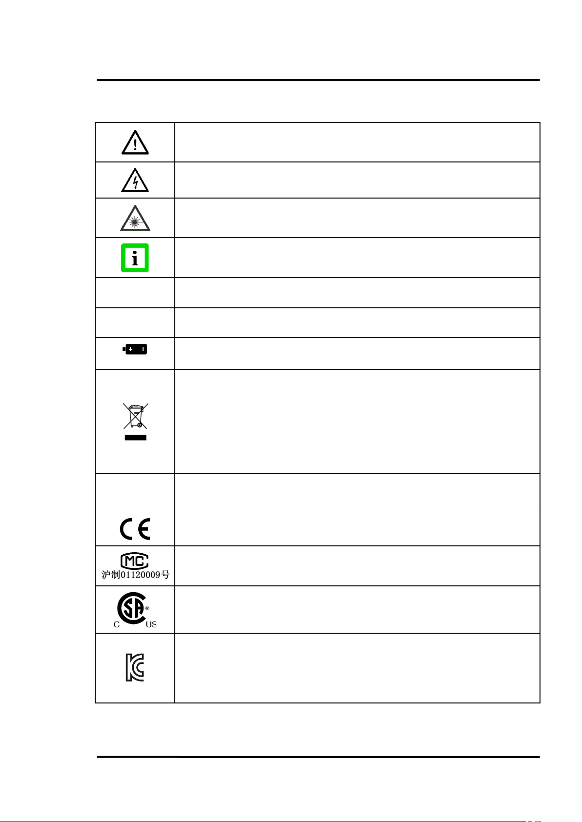
Risk of danger. Important information. See manual.
Hazardous voltage. Risk of electrical shock.
Warning Laser.
RoHS
Helpful information regarding the optimal use of the instrument.
Celsius
Fahrenheit
Lithium-Ion Battery
This product complies with the WEEE Directive (2002/96/EC) marking
requirements. The affixed label indicates that user must not discard this
electrical/electronic product in domestic household waste. Product Category:
With reference to the equipment types in the WEEE Directive Annex I, this
product is classed as Category 9 "Monitoring and Control Instrumentation." Do
not dispose of this product as unsorted municipal waste. Go to Fluke’s website for
Conforms to European Union directive.
Conforms to China Metrology Certification
CMC mark with Implement standard Q/SXAV 16
Conforms to Canadian Standards Association Certification.
Electromagnetic Compatibility Applies to use in Korea only. Class A Equipment
(Industrial Broadcasting & Communication Equipment)
This product meets requirements for industrial (Class A) electromagnetic wave equipment and the
Find Quality Products Online at: sales@GlobalTestSupply.com
3i Plus Rev. A1 Jan 2015 7
seller or user should take notice of it. This equipment is intended for use in business environments
www.GlobalTestSupply.com
Page 8

Safety Instructions
Class A digital device: This equipment has been tested and found to comply with
be required to correct the interference at their own expense.
the limits for a Class A digital device, pursuant to Part 15 of the FCC Rules. These
limits are designed to provide reasonable protection against harmful interference
when the equipment is operated in a commercial environment. This equipment
generates, uses, and can radiate radio frequency energy, and if it is not installed
and used in accordance with the instruction manual, it may cause harmful
interference to radio communications. Operation of this equipment in a
residential area is likely to cause harmful interference, in which case the user will
See figure below for the safety markings.
Find Quality Products Online at: sales@GlobalTestSupply.com
8 Rev. A1 Jan 2015 3i Plus
www.GlobalTestSupply.com
Page 9

Safety Instructions
Warnings
A warning identifies conditions and procedures that are dangerous to the user.
To prevent possible electrical shock, fire, or personal injury follow these guidelines:
• Read all safety information before you use the product.
• Use the product only as specified, or the protection supplied by the product can be
compromised.
• Do not use the product around explosive gas, vapor, or in damp or wet environments.
• Do not use the product if it operates incorrectly.
• See emissivity information for actual temperatures. Reflective objects result in lower than
actual temperature measurements. These objects pose a burn hazard.
• Do not look directly into the laser with optical tools (for example, binoculars, telescopes,
microscopes). Optical tools can focus the laser and be dangerous to the eye.
• Do not look into the laser. Do not point laser directly at persons or animals, or indirectly off
reflective surfaces.
• Use the product only as specified, or hazardous laser radiation exposure can occur.
• Do not use laser viewing glasses as laser protection glasses. Laser viewing glasses are used
only for better visibility of the laser in bright light.
• Do not open the product. The laser beam is dangerous to eyes. Have the product repaired
only through an approved technical site.
• Have an approved technician repair the product.
Cautions
A caution identifies conditions and procedures that can cause damage to the instrument or the
equipment under test.
For safe operation and maintenance of the product:
• Remove the batteries if the product is not used for an extended period of time, or if stored in
temperatures above 50°C (122°F). If the batteries are not removed, battery leakage can damage
the product.
• Recharge the batteries when the low battery indicator appears to prevent incorrect
measurements.
• Have the product repaired before use if the batteries leak.
• Do not short the battery terminals.
• Do not keep cells or batteries in a container where the terminals can be shorted.
• Do not put battery cells and battery packs near heat or fire. Do not put in sunlight.
To avoid damage to the product or the equipment under test, protect them from:
• EMF (electro-magnetic fields) from arc welders, induction heaters, etc.
• Static electricity
Find Quality Products Online at: sales@GlobalTestSupply.com
3i Plus Rev. A1 Jan 2015 9
www.GlobalTestSupply.com
Page 10

Safety Instructions
Battery Warning
The battery is a safety device. Do not attempt to disassemble or alter the battery. Always observe the
following precautions:
• Do not short-circuit the battery by directly connecting the negative terminals with positive
terminal.
• Do not heat the battery or discard it in a fire.
• Do not expose the battery to temperatures over 50°C (122°F). Keep the battery away from fire
and other heat sources.
• Do not charge the battery near a heat source, such as, a fire or heater.
• Do not leave the battery in direct sunlight.
• Do not pierce the battery with a sharp object, hit or step on it.
• Do not use a damaged battery.
• Do not apply solder to a battery.
• Do not connect the battery to an electrical power outlet.
To prevent the battery bursting, igniting, or fumes from the battery causing equipment damage,
always observe the following precautions:
• Do not immerse the battery in water or allow it to get wet.
• Do not place the battery in a microwave oven or pressurized container.
• If the battery leaks or emits an odor, remove it from all possible flammable sources.
• If the battery emits an odor or heat, is deformed or discolored, or in a way appears abnormal
during use, recharging or storage, immediately remove and stop using it.
Instrument
• If the unit is exposed to significant changes in ambient temperature (hot to cold or cold to
hot), allow 30 minutes for temperature stabilization before taking measurements.
• Do not operate the unit near large electrical or magnetic fields such as arc welders and
induction heaters. These fields can cause measurement errors.
• For the short wavelength units (e.g., 1.0 µm and 1.6 µm) — avoid taking temperature
measurements in bright sunlight. High levels of ambient light may produce apparently valid
high-temperature readings when no target is in the thermometer’s field-of-view.
Find Quality Products Online at: sales@GlobalTestSupply.com
10 Rev. A1 Jan 2015 3i Plus
www.GlobalTestSupply.com
Page 11

Product Description
Model
Temperature
Optics
Spectral
Sighting
700 to 3000°C
(1292 to 5432°F)
700 to 3000°C
(1292 to 5432°F)
400 to 2000°C
(752 to 3632°F)
400 to 2000°C
(752 to 3632°F)
2 Product Description
The Raynger 3i Plus Series of instruments are portable infrared temperature measurement devices.
Each model is rugged and easy to use for making fast, noncontact, nondestructive temperature
measurements. They can measure product temperatures during manufacturing or storage without
contaminating or marring the product.
Figure 1: Raynger 3i Plus Series
The Raynger 3i Plus Series thermometer is an upgraded version of Ranger 3i Series. It provides high
performance with better accuracy, increased optical resolution, a larger memory and other highlighted
functions. It is the best solution for monitoring process temperature and initial breakdown for the
steel, cement, heat treatment, and petrochemical industries.
Refer to the following table for a list of standard models along with their temperature ranges, optical
resolutions, spectral ranges, and sighting systems.
RAYR3IPLUS1ML
RAYR3IPLUS1MSCL
RAYR3IPLUS2ML
RAYR3IPLUS2MSCL
Table 1: Available Models
250:1 1 µm Dual laser
250:1 1 µm Dual laser + Scope
250:1 1.6 µm Dual laser
250:1 1.6 µm Dual laser + Scope
Find Quality Products Online at: sales@GlobalTestSupply.com
3i Plus Rev. A1 Jan 2015 11
www.GlobalTestSupply.com
Page 12

Product Description
2.1 Features
The Raynger 3i Plus Series has the following features:
• Dual laser sighting
• Current temperature plus MAX, MIN, DIF, AVG temperatures
• Audible/visual alarms for target temperature, ambient temperature, and low battery
• Adjustable emissivity and predefined emissivity table
• Background temperature compensation
• Transmissivity compensation
• User selectable °C or °F
• Profile definition to convenient measurement
• Curve to display trend with selectable time span
• Tripod mount
• Auto off
• 12- or 24-hour real time clock
• Last reading hold (20 seconds)
• English and Chinese user interface
• Data storage: up to 4,900 units with location, date, and time stamp
• Trigger lock
• USB 2.0 computer interface
• Lithium-ion battery, charged with or without unit
• Red dot scope sighting (scope model)
• Special material for 120°C (248°F) high temperature
• Warning system to prevent high temperature damage
®
• Bluetooth
• Documenting personal computer (PC) software
wireless technology1 for communication with a mobile device
1
Bluetooth® is a registered trademark owned by Bluetooth SIG, Inc.
Find Quality Products Online at: sales@GlobalTestSupply.com
12 Rev. A1 Jan 2015 3i Plus
www.GlobalTestSupply.com
Page 13

3 Technical Data
3.1 Measurement Specifications
Temperature Range
1M 700 to 3000°C (1292 to 5432°F)
2M 400 to 2000°C (752 to 3632°F)
Spectral Response
1M 1.0 µm
2M 1.6 µm
Optical Resolution D:S
All models 250:1
System Accuracy
1M ± (0.5% or reading + 1°C) for < 2700°C
2M ± (0.5% or reading + 1°C)
Repeatability
3
± (0.3% or reading + 1°C)
1
16 mm spot @ 4000 mm distance (0.63 in @ 157 in)
2
± (0.5% or reading + 2°F) for < 4892°F
± 2% or reading for > 2700°C (4892°F)
± (0.5% or reading + 2°F)
± (0.3% or reading + 2°F)
Technical Data
Temperature Resolution
Display ± 0.1°C (0.1°F)
Exposure Time 40 ms (95%)
Display Refresh Time 200 ms
Emissivity 0.01 to 1.00
Signal Processing Max / Min / Avg / Diff
1
at 90% energy in minimum and distance 4000 mm (157 in.)
2
Calibration geometry at ambient temperature 23°C ±2°C (73°F ±4°F), emissivity = 1.0
3
Calibration geometry at ambient temperature 23°C ±2°C (73°F ±4°F), emissivity = 1.0
Find Quality Products Online at: sales@GlobalTestSupply.com
3i Plus Rev. A1 Jan 2015 13
www.GlobalTestSupply.com
Page 14

Technical Data
3.2 Optical Charts
Figure 2: Spot Size Charts
3.3 General Specifications
Operating Temperature 0 to 50°C (32 to 122°F)
Storage Temperature -20 to 60°C (-4°F to 140°F) without battery
Operating Humidity 10 to 90% RH, not condensing at 30°C (86°F)
Environmental Rating IP40 (NEMA 1)
Drop Performance 1 m (3.3 ft)
Operating Altitude ≤ 2 000 m (6,500 ft.)
Storage Altitude ≤ 12 000 m (40,000 ft.)
Size
Standard 218 x 172 x 74 mm (8.6 x 6.8 x 2.9 in.)
with scope 218 x 222 x 74 mm (8.6 x 8.7 x 2.9 in.)
Find Quality Products Online at: sales@GlobalTestSupply.com
14 Rev. A1 Jan 2015 3i Plus
www.GlobalTestSupply.com
Page 15

Technical Data
Weight
Standard 700 g (25 oz)
with scope 950 g (34 oz)
Display Illuminated backlight display
(On/Off, white color, orange color)
display Hold (20 s)
Laser Dual laser (EN60825 Class 2, FDA Class II)
3.4 Electrical Specifications
Power Supply Battery or USB
Battery Lithium-ion, single cell, 3.6 V, 2500 mAh
1
Battery Life
USB Version 2.0, Mini USB (type B)
Bluetooth Version 4.0
24 h
Item Specifications
Frequency 2402 MHz in 2 MHz steps
Data Rate and Modulation 1Mbps, GFSK
Number of Channels 40:37 data / 3 advertising (0,12,39)
Receive Sensitivity (w/ chip antenna) -95 / -89 dBm
Output Power -23 to 4 dBm
Link Budget Up to 99 dB
RX/TX Turnaround 150 µs
3.5 Scope of Delivery
The scope of delivery includes the following:
• Raynger 3i Plus
• Carrying case
• CD with software for real-time graphic temperature display and data download, and
operator's manual (PDF format)
• Lithium-ion battery 2.5 Ah
• Mini USB port adapter (100 – 240 VAC 50/60 Hz)
• Mini USB to DC jack converter for charging battery separately
• 1.5 m (4.9 ft.) computer cable with USB to Mini USB
• Operator’s manual (printed format)
1
Laser: off, Bluetooth: off
Find Quality Products Online at: sales@GlobalTestSupply.com
3i Plus Rev. A1 Jan 2015 15
www.GlobalTestSupply.com
Page 16

Basics
4 Basics
4.1 Measurement of Infrared Temperature
All objects emit an amount of infrared radiation according to their surface temperature. The intensity
of the infrared radiation changes according to the temperature of the object. Depending on the
material and surface properties, the emitted radiation lies in a wavelength spectrum of approximately
1 to 20 µm. The intensity of the infrared radiation (”heat radiation”) is dependent on the material. For
many substances this material-dependent constant is known. It is referred to as ”emissivity value”
(see section 10.2 Typical Emissivity Values, page 56.
Infrared thermometers are optical-electronic sensors. These sensors are able to detect ”radiation of
heat.” Infrared thermometers are made up of a lens, a spectral filter, a sensor, and an electronic signalprocessing unit. The task of the spectral filter is to select the wavelength spectrum of interest. The
sensor converts the infrared radiation into an electrical signal. The signal processing electronics
analyzes the electrical signal and converts it into a temperature measurement. As the intensity of the
emitted infrared radiation is dependent on the material, the required emissivity can be selected on the
sensor.
The biggest advantage of the infrared thermometer is its ability to measure temperature without
touching an object. Consequently, surface temperatures of moving or hard to reach objects can easily
be measured.
4.2 Emissivity of Target Object
Determine the emissivity of the target object as described in section 10.1 Determination of Emissivity,
page 56. If emissivity is low, measured results could be falsified by interfering infrared radiation from
background objects (e.g., heating systems, flames, fireclay bricks, etc., close beside or behind the target
object). This type of problem can occur when measuring reflecting surfaces and very thin materials
such as plastic films and glass.
This measuring error can be reduced to a minimum if particular care is taken during installation, and
the sensing head is shielded from these reflecting radiation sources.
Find Quality Products Online at: sales@GlobalTestSupply.com
16 Rev. A1 Jan 2015 3i Plus
www.GlobalTestSupply.com
Page 17

Operation
modes and functions, and for full
5 Operation
5.1 Quick Start
To use the instrument right away, complete the following steps:
1. Point the instrument at the object the user wants to measure (as perpendicular as possible to
the object) and pull the trigger. The current temperature (in °C or °F), emissivity value, and
maximum and minimum measured temperature are displayed.
2. Change the emissivity value to correspond to the targeted material by pressing the <F1> key
twice to show the target material table. Press the ▲ and ▼ buttons to select the target material.
For complete definitions of the instrument’s
explanation of operation, refer to the later sections.
5.2 Overview
Portable infrared thermometers measure surface temperatures without touching the surface. They
collect the infrared energy radiated by a target and compute its surface temperature. They also
compute the running average, and maximum/minimum/differential temperatures and present them
on a digital display in either degrees Celsius or Fahrenheit. The instrument is battery-powered or can
be powered by a computer’s USB interface. Internal memory circuits store temperature data for later
recall, and a data-logging feature allows users to store and multiple temperature, emissivity, and
alarm readings (valuable for comparative analysis).
The following figure shows the features of the portable infrared thermometer.
Find Quality Products Online at: sales@GlobalTestSupply.com
3i Plus Rev. A1 Jan 2015 17
www.GlobalTestSupply.com
Page 18

Operation
Nose with Temperature
Tripod Screw
Trigger
Battery Cover and Screw
USB Interface
Save Key
Return Key
3x Soft Keys
Red Dot Scope
Polaroid Frame
Scope Adjustable Screw
2 Laser Aperture
Sensor inside
Figure 3: Portable Thermometer with Scope
The portable thermometer has the following:
Trigger: One-stage trigger, which activates the unit to take temperature readings.
Control Panel and Display: All controls (except the trigger) are located on the control panel. The
display shows temperature and setup values, mode and operating information.
Mini USB Output: Connects the instrument to the PC for downloading data or to DC Adaptor for
charging the battery.
Nose with Temperature Sensor inside: Has the thermistor on the nose for high temperature
protection.
Sighting System: Laser or red dot scope sighting is provided with each model for aiming. Note: Read
the laser warning label before operating the laser.
Polaroid Frame: To adjust brightness of red dot scope.
5.3 Distance and Spot Size
As the distance (D) from the object being measured increases, the spot size (S) of the area measured by
the instrument becomes larger. For the relationship between distance and spot size (D:S), see section
3.2 Optical Charts, page 14.
During measurements, please make sure that the target is larger than the instrument’s measurement
spot size at that distance. The smaller the target, the closer user should be to it.
Find Quality Products Online at: sales@GlobalTestSupply.com
18 Rev. A1 Jan 2015 3i Plus
www.GlobalTestSupply.com
Page 19
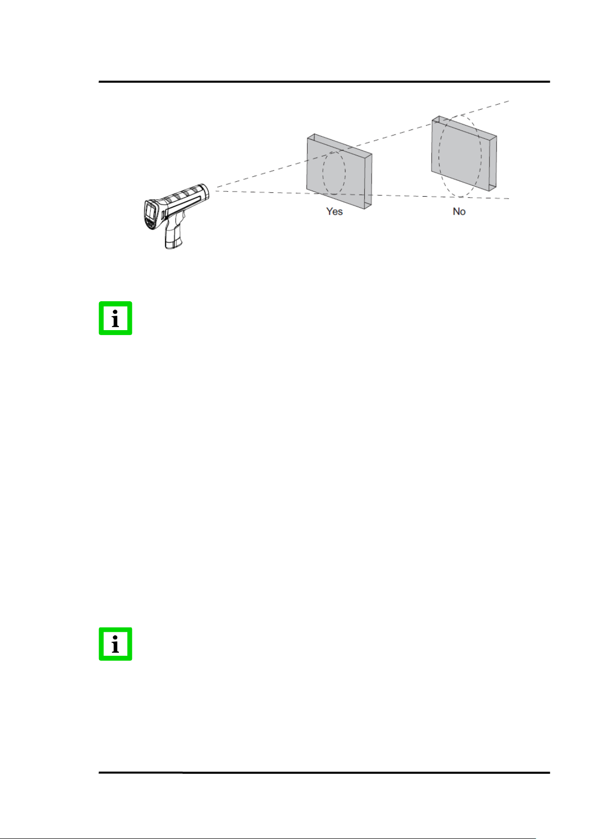
For accurate measurements the target size must be at least two times bigger than the
Spot diameter
there is
Operation
Figure 4: Field of View
5.4 High Temperature Nose
The instrument has a specially designed nose with high temperature resistant plastic material to avoid
damage from high temperature targets. On the other hand, please avoid over exposure when aiming
at a high-temperature target.
There is a temperature sensor inside the nose. During measurement, the instrument is monitoring the
temperature of the nose. If it is too hot, there will be a warning on the LCD display (ambient highlight
display and backlight change to red plus audible buzzer). Please move the unit away from the hightemperature target when seeing this alarm.
5.5 Power Supply
The instrument is powered by a battery or USB cable when connect to the PC. The battery is located in
the base of the handle.
The instrument provides two charging methods:
• AC adaptor through Mini USB port on the right side of the unit.
• Remove the battery, and use the AC adaptor plus Mini USB-to-DC jack converter to charge.
An indicator on the battery will show a “charging” red light and “charge complete” green
light.
The instrument can be powered when connecting the USB cable to the PC but
no charging since many USB ports have not enough power capability!
Find Quality Products Online at: sales@GlobalTestSupply.com
3i Plus Rev. A1 Jan 2015 19
www.GlobalTestSupply.com
Page 20

Operation
5.6 Display
The display retains the last infrared measurement for 20 s when the trigger is released and <HOLD> is
shown on the display. To hold the infrared temperature, release the trigger until <HOLD> shows on
the display.
5.7 Sighting
5.7.1 Dual Laser
All models use a dual laser method to show the measurement spot position and size. The two laser
points show the diameter of the spot circle, with the middle laser point as the center of the spot circle.
5.7.2 Red Dot Scope
The scope models for the Raynger 3i Plus series provide an additional red dot scope; the measurement
target can be seen through the scope. That aiming system can be used when the laser points are hard
to see due to the brightness of the target.
The scope's red dot shows the center of the measuring spot circle, which does not display on the real
object under measurement.
The intensity of the field sight can be adjusted by rotating the knob on the top of the instrument while
keeping the brightness of the red dot. This function is helpful for the user to clearly see the red dot
position when the instrument is measuring high-temperature objects.
If the scope's red dot does not match with the circle of the two laser points, use the following
adjustment method:
1. Open the two circular rubber caps on the top of the unit, and the scope's two adjustable
screws are shown.
2. Affix the unit to a tripod.
3. Aim at a target 4 m (13 ft.) off in the distance, like a wall, for viewing the two lasers clearly.
4. Adjust the two screws on the aiming scope to the center of the two laser points. Please try to
look straight through the aiming scope.
5. Remove the unit from the tripod.
6. Close the two circular rubber caps.
Warning: Please do not use the unit with the two rubber caps open, since unexpected contact with
the screws may introduce noise pulse to the units, resulting in noise readings or disorder of the
display
5.8 Temperature Records
The instrument can store measurement records, including time, date, emissivity, and measurement
record numbers. It can store 1,000 records for basic test data, 10 pcs trend display and 300 records for
profile.
The following types of data are available:
• Basic test data: Test data without a dedicated setting like profile. User can record random
measurement data in this area with a maximum 1,000 records.
• Trend data the data saved under trend mode which includes three screens of data with 360
test values. The data will be saved in a curve format and the user can review the value of each
test point with PC software. Press <View> to review the trend picture. User can press up and
Find Quality Products Online at: sales@GlobalTestSupply.com
20 Rev. A1 Jan 2015 3i Plus
www.GlobalTestSupply.com
Page 21

Operation
down arrows to select each saved trend data. The user can then use left and right arrows to
view the three screens for each piece of trend data.
• Profile test data: Profile setting under which 300 test data records (maximum) are saved.
Profile test data is defined as the test data under profile setting which could save maximum
300 records. By using the load value of each profile, these test data has been divided by group
according to the profile setting in PC software. User can find the temperature distribution
status in one group and convenient the measurement by using the setting in advance.
5.9 Save Button
The instrument can store up to multiple data records. The information below is stored in each record:
• Record number
• IR temperature in °F or °C
• Date/Time
• Emissivity
To save the current temperature reading (Basic test data):
1. Pull the trigger to take a measurement.
2. Release the trigger to stop taking the measurement.
3. Push the <Save> soft key to enter the Save menu.
4. Push the <Yes> soft key to save the reading.
The user can also push the <Cancel> soft key to not save the reading.
The <Save> soft key is also used to save records as profile or trend.
5.10 Menu
The instrument can display two languages, English and Simplified Chinese. To change the displayed
language, see section 5.10.10.6 Language, page 28.
5.10.1 Overview
There are many settings that can be changed with the menu. The following figure shows the LCD and
menu interface.
Find Quality Products Online at: sales@GlobalTestSupply.com
3i Plus Rev. A1 Jan 2015 21
www.GlobalTestSupply.com
Page 22
Operation
② ③ ④ ⑤ ⑥ ⑦ ⑧
①
⑭
⑬
⑫
⑪
⑩
⑨
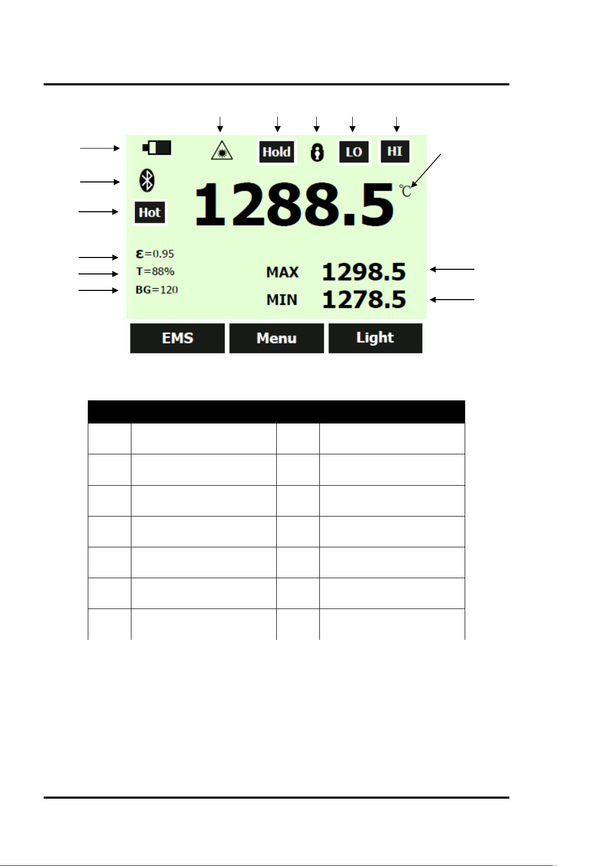
Figure 5: User Interface
Number Description Number Description
①
②
③
④
⑤
⑥
⑦
The Raynger 3i Plus series has three soft keys (F1, F2, and F3) just below the LCD display. There is a
“Soft Key Bar” on the LCD above the three soft keys to define their active function. By using soft keys,
the instrument has a convenient menu function. Each menu item and function is explained in detail in
the following sections.
In addition to the soft keys, there are also the <Save> and <Return> soft keys below the LCD display.
Selecting the <Menu> soft key advances the menu to the next level. The following table shows the toplevel description of the menu.
Battery Symbol
Laser Indicator
Scan/Hold
Lock/Unlock
Low Temperature Alarm
High Temperature Alarm
Main Temperature Display
Table 2: Menu Overview
⑧
⑨
⑩
⑪
⑫
⑬
⑭
Max. Value Display
Min. Value Display
Background Temp. Compensation
Transmissivity
Emissivity
“Hot” Warning Area
Bluetooth Symbol
Find Quality Products Online at: sales@GlobalTestSupply.com
22 Rev. A1 Jan 2015 3i Plus
www.GlobalTestSupply.com
Page 23

Operation
Level
<F1>
Description
<F2>
<F3>
Description
3
MnMx
Enables minimum/maximum
Menu
Avg
Enables average/difference
4
Lock/Unlock
Locks/unlocks the trigger button
Menu
Laser
Toggles the laser
Time/Date, Alarm, Transmissivity,
Language
6
°C/°F
Toggles between C and F
Menu
Scope
Toggles the red dot in the scope
1 EMS Sets the emissivity value Menu Light Toggles the LCD backlit
2 Profile Calls predefined profiles Menu Trend Reviews recorded trends
5 Setup
<Save> button Save Reading to Memory <Return> button Back to Last Menu
Background Temperature, Bluetooth,
Table 3: Top-Level Menu Description
Menu Log
Review/Delete recorded
temperatures
5.10.2 EMS - Emissivity
The <Emissivity> menu includes a list of pre-defined materials and their typical emissivity values, see
section 10.2 Typical Emissivity Values, page 56. The instrument’s default emissivity value is 1.00.
To access the Emissivity menu:
1. Push the <Menu> soft key until EMS (emissivity) is shown as the right soft key function.
2. Push the <EMS> soft key.
The user can push the table soft key to access the emissivity list. The user can also push the <No.> soft
key to manually enter the typical emissivity of a material.
If the Emissivity table is accessed, a list of materials and their suggested emissivity is shown.
1. Use the down arrow to navigate through the list.
2. Push the <Done> soft key to choose the desired material.
To enter an emissivity value manually:
1. Push the <No.> soft key.
2. Use the down or up arrow soft key to change the entry. Hold down the up or down arrow soft
key to increase the rate of change.
3. Push the <Done> soft key when finished to return to the main menu.
5.10.3 Light
The instrument has a backlit display. The backlight can be toggled by pushing the <Light> soft key.
5.10.4 Profile
To manage regular testing points, different profiles can be created by the Raynger 3i Plus software.
Each profile includes the settings for Emissivity, Alarm Temperature, Transmissivity, Background
Temperature, etc., as well as a unique profile name. When the setting is ready, the user can simply
select the profile name to call up the settings, save data and review accordingly.
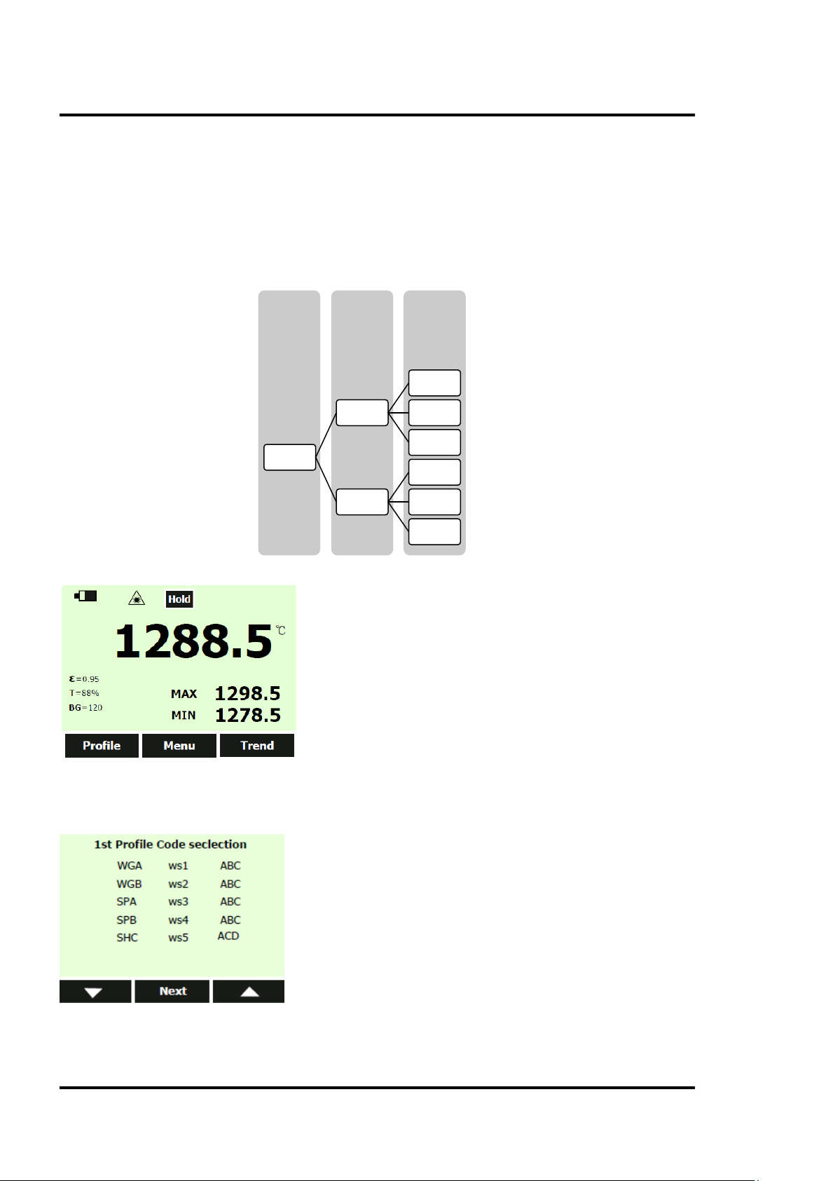
The maximum number of test points is 300. These test points are arranged in three levels, and the
maximum allowed for the second level is 50. The first and second levels could be represented by three
Find Quality Products Online at: sales@GlobalTestSupply.com
3i Plus Rev. A1 Jan 2015 23
www.GlobalTestSupply.com
Page 24
Operation
characters (combination of number and letter), and the third level can be defined by a sequential test
point number. The user can define the unique structure to meet complicated needs.
The following example can be regarded as a sequential structure:
• First level: WGA and WGB represent two heating ovens.
• Second level: ECA and ECB belong to WGA. The second level can be set up to 50 test points.
• Third level: Indicates the location number in each second-level folder. The sums for location
numbers in all third levels can up to 300 points.
3rd Level 2nd Level 1st Level
1
ECA
WGA
ECB
Examples are as follows:
Press <Profile> to enter the first level menu selection. Each displayed name is edited under the PC
interface, and then uploads to the instrument. Here the user can continue to the next screen using the
arrow keys if the item quantity is more than 15.
...
100
1
...
20
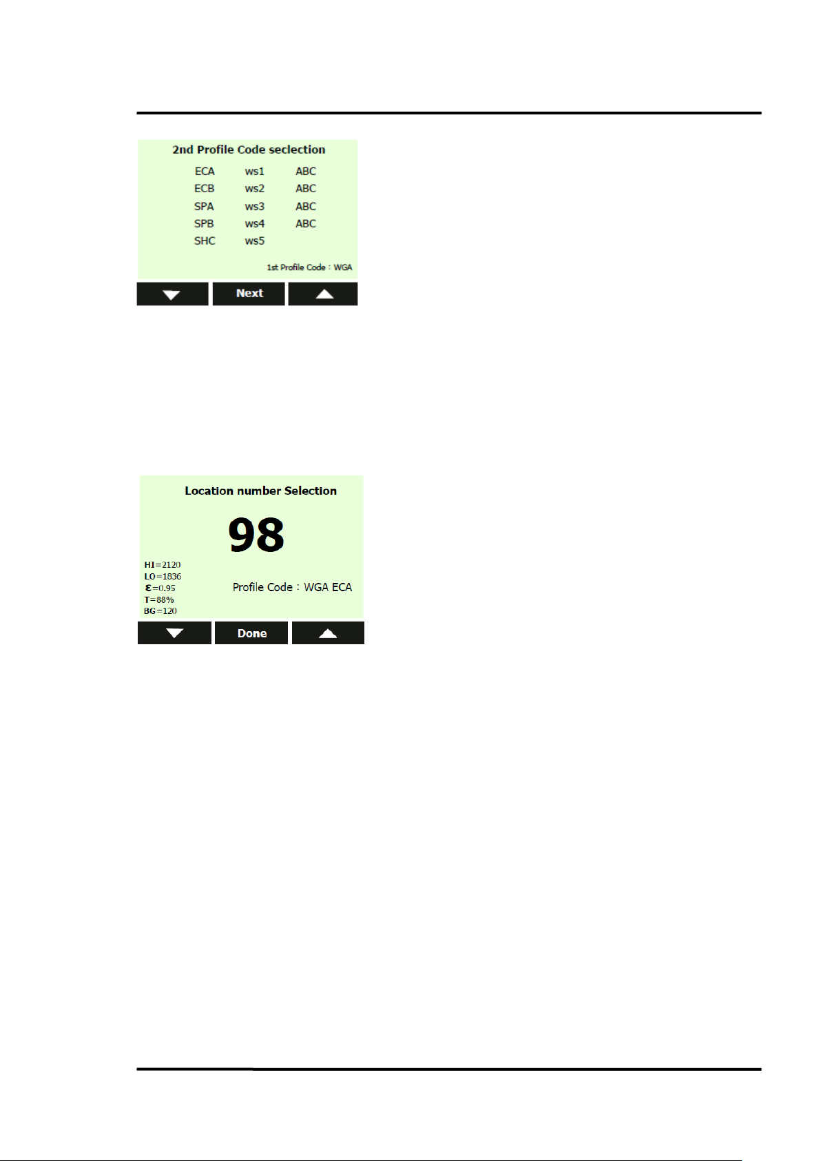
Press <Next> to continue to the second level menu, and upload to the instrument. Here, the user can
also continue to the next screen using the arrow keys.
Find Quality Products Online at: sales@GlobalTestSupply.com
24 Rev. A1 Jan 2015 3i Plus
www.GlobalTestSupply.com
Page 25
Operation
Choose the <Next> button, and the user can select location number and use various preset parameters
to perform test.
In the following example, selecting profile code WGA ECA location number 98 has a setting of:
High -temperature Alarm HI = 2120
Low -temperature Alarm LO = 1836
Emissivity ε = 0.95
Transmissivity T = 88%
Background Temperature Compensation BG = 120
Press <Done> to adopt this setting for this location and perform normal measurement.
If the user chooses to save the test data, the test point number will auto jump to the next one. If the
user doesn’t save the test data, the profile will keep the current test point.
Note: In this mode, the user can modify the emissivity values to adapt to field test conditions and use
<Save> soft key to save this change.
5.10.5 Trend
Press the <Menu> button, until <Trend> displays for the right function key and press enter.
The instrument provides two modes to display the trend.
• <Auto>: The user does not need to consider how to set upper and lower limits for the
displayed temperature. The temperature axis will be changed according to the actual
measurement range. After the user chooses an appropriate time span, the curve can be
displayed on the screen.
• <Manual>: The user should manually set the upper and lower limits for the Y-axes and the
time span for the X-axes in accordance to his needs.
Press the left key to enter the <Auto> mode. Enter the time axis settings. Press the arrow keys to select
the time interval. The unit can select 20 ms, 200 ms, 1 s, 10 s, 1 min, and 5 min time spans. After the
user has confirmed the selected time span and presses the trigger, the trend can be displayed on the
screen.
User also can choose the <Manual> mode to set the upper and lower limits and the time span.
Find Quality Products Online at: sales@GlobalTestSupply.com
3i Plus Rev. A1 Jan 2015 25
www.GlobalTestSupply.com
Page 26

Operation
The instrument will save three pages of curves when the user presses <Save>.
The maximum record in trend mode is 10 pcs curve; each curve can be displayed in three pages.
The figure below is under trend auto mode.
1. The data show on Y-axes is automatically displayed using the maximum and minimum value
in the record period.
2. The data show on X-axes is calculated by the time span the user has chosen.
Every page can store 120 points, so if you choose a time span with 200 ms, the maximum value on Xaxes should be 24 s.
5.10.6 MnMx – Minimum, Maximum
The instrument can measure the minimum (Min), maximum (Max) temperatures each time a reading
is taken.
To turn on the Min-Max mode:
1. Push the <Menu> soft key until <MnMx> (Min-Max) in shown as the F1 soft key function.
2. Push the <MnMx> soft key.
The display shows now the minimum and maximum readings.
5.10.7 Avg – Average
The instrument can measure the average (Avg) and differential (Dif) temperatures each time a reading
is taken.
To turn on the Avg/Dif mode:
1. Push the <Menu> soft key until <Avg> shows as the right soft key function.
2. Push the <Avg> soft key.
The display shows the average reading and the differential reading which is the difference between
the present minimum and the maximum temperature.
Averaging can be useful when an average temperature over a specific duration is desired, or when a
smoothing of fluctuating temperature is required. The signal is smoothed depending on the defined
time basis. In other words, the output signal tracks the detector signal with significant time delay but
noise and short peaks are damped.
5.10.8 Lock – Trigger Button
The instrument’s trigger can be locked to take temperature readings continuously without pressing
the trigger button all the time.
To lock the trigger button:
Find Quality Products Online at: sales@GlobalTestSupply.com
26 Rev. A1 Jan 2015 3i Plus
www.GlobalTestSupply.com
Page 27

Operation
1. Push the <Menu> soft key until the lock symbol shows as the left soft key function.
2. Push the soft key to lock the trigger. The lock symbol
a locked trigger. When the trigger is locked, the soft key changes to unlock. Push this soft key
to unlock the trigger.
5.10.9 Laser
The laser is to be used for aiming purposes only. It turns off when the trigger is released.
To enable or disable the laser:
1. Push the <Menu> soft key until <Laser> shows as the right soft key function.
2. Push the <Laser> soft key to enable or disable the laser. The laser symbol is shown on the
display when the laser is enabled.
To prevent eye damage and personal injury, do not look into the laser. Does not point
Do not point the laser directly at persons or animals or indirectly off reflective surfaces.
5.10.10 Setup
From the <Setup> menu, the time and date, alarm, transmissivity, background temperature, display
language and Bluetooth switch can be changed. In the <Setup> menu, transmissivity, and background
temperature can be set by the user.
is shown on the display to designate
5.10.10.1 Time/Date
To change the time on the instrument:
1. Push the <Menu> soft key until <Setup> shows as the left soft key function.
2. Push the <Setup> soft key to enter the <Setup> menu.
3. Push the down arrow soft key to select <Time/Date>.
4. Push the <Enter> soft key.
5. Push the <Time> soft key.
6. Push the necessary time format soft key (24-hour or 12-hour).
7. Use the up and down soft keys to the desired hour.
8. Push the <Next> soft key to select the minutes.
9. Use the up and down soft keys to the desired minute.
10. When in 12-hour mode, push the <Next> soft key to highlight the AM/PM parameter.
11. Use the up and down soft key to change to <AM> or <PM>.
12. Push the <Done> soft key when finished. The display reverts to the first page of the Time/Date
menu.
To change the date on the instrument:
1. From the main menu, push the <Menu> soft key until <Setup> shows as the left soft key
function.
2. Push the <Setup> soft key.
3. Push the down arrow soft key to select <Time/Date>.
4. Push the <Enter> soft key.
5. Push the <Date> soft key.
6. Select the date format: <Day/Month/Year> (DMY) or <Month/Day/Year> (MDY).
7. Use the up and down soft keys to change the selected parameter.
8. Push the <Next> soft key and the arrow soft keys to select the month, date, or year
parameters.
9. Use the up and down soft keys to change the selected parameter.
Find Quality Products Online at: sales@GlobalTestSupply.com
3i Plus Rev. A1 Jan 2015 27
www.GlobalTestSupply.com
Page 28

Operation
10. Push the <Next> soft key to move through each parameter.
11. Push the <Done> soft key when finished. The display reverts to the start of the <Time/Date>
menu.
5.10.10.2 Alarm
The instrument has a programmable alarm to designate high or low readings, depending on the
thresholds entered. When the alarm level is reached, an alarm will sound and the display will flash
orange and white. To set either the high or low alarm:
1. Push the <Menu> soft key until <Setup> shows as the right soft key function.
2. Choose the <Alarm> soft key to access the <Alarm> menu.
3. Push either the <Hi> or <Lo> soft key, depending on which alarm will be set.
4. Push the <On> soft key to turn the alarm on.
5. Push the <Off> soft key to turn the alarm off.
6. Use the <Set> soft key to access the <Hi> or <Lo> Alarm Set menu.
7. Use the down or up soft keys to change the alarm setting.
8. Once the necessary settings have been entered, push the <Done> soft key.
5.10.10.3 Transmissivity
To change the <Transmissivity> value when measuring target temperature through glass windows:
1. Push the <Menu> soft key until setup shows as the right soft key function.
2. Choose <Transmissivity> to access the <Alarm> menu.
3. Push the <On> soft key to turn the transmissivity on.
4. Use the <Set> soft key to access the transmissivity set menu.
Transmissivity could be set between 1% and 100%.
5. Push the <Off> soft key to turn <Transmissivity> off.
5.10.10.4 Background Temperature
This feature is useful when the target emissivity is below 1.0 and the background temperature is not
significantly lower than the target temperature. For instance, the higher temperature of a furnace wall
could lead to too-high temperatures being measured especially for lower emissivity targets. A built-in
ambient background temperature utility compensates for the impact of the reflected radiation in
accordance to the reflective behavior of the target. User can set this function as follows:
1. Push the <Menu> soft key until setup shows as the right soft key function.
2. Choose <Background Temperature> to access the <Alarm> menu.
3. Push the <On> soft key to turn the <Background Temperature> on.
4. Use the <Set> soft key to access the <Background Temperature Set> menu.
5. Push the <Off> soft key to turn the <Background Temperature> off.
5.10.10.5 Bluetooth
Menu to turn Bluetooth on and off.
5.10.10.6 Language
To change the display language:
1. From the main menu, push the <Menu> soft key until <Setup> shows as the left soft key
function.
2. Push the <Setup> soft key.
3. Use the down arrow soft key to move the indicator to <Language>.
4. Push the <Enter> soft key.
5. Push the <F1> soft key to complete the language selection or push the <Back> soft key to
return to the Setup menu.
Find Quality Products Online at: sales@GlobalTestSupply.com
28 Rev. A1 Jan 2015 3i Plus
www.GlobalTestSupply.com
Page 29

Operation
Parameter
Factory Default
Scope
OFF
Laser
OFF
Date Format
DD/MM/YY
Time
00:00:00
Temperature Unit
Celsius
Transmissivity
100%
Background Compensation Enable
OFF
High Alarm Temperature
Upper limit of measurement range
Low Alarm Enable
OFF
Trend Curve Limit Mode
Auto
5.10.10.7 To Default
To restore the instrument to the original factory default settings, press the <To Default> soft key. The
following table provides the values in case of a factory default.
White Backlight OFF
Orange Backlight OFF
Buzzer OFF
Date 2014.01.01
Time Format 24-Hour
Bluetooth Enable False
Language English
Emissivity 1.00
Transmissivity Enable OFF
Background Compensation Temperature 25°C (77°F)
High Alarm Enable OFF
Low Alarm Temperature Lower limit of measurement range
Trend Curve Upper-Limit Upper limit of measurement range
Trend Curve Lower-Limit Lower limit of measurement range
Trend Time Span 200 ms
Table 4: Factory Default Values
5.10.11 Log
This menu allows reviewing or deleting of previously stored temperature records.
To review temperature records follow the steps given below:
1. Push the <Menu> soft key until <Log> shows as the right soft key function.
2. Push the <Log> soft key and the select the temperature record of interest (Profile, Basic, or
Trend) to review it.
Additionally, pushing the <Delete> soft key allows you to remove an individual or all sets of the
temperature record.
Find Quality Products Online at: sales@GlobalTestSupply.com
3i Plus Rev. A1 Jan 2015 29
www.GlobalTestSupply.com
Page 30

Operation
Delete All Data
To delete all of the records:
1. Push the <All> soft key.
2. At the confirmation screen, push the <Yes> soft key.
Delete Individual Data Records
To delete individual records:
1. Push the one soft key.
2. Use the down and up arrow soft keys to access the desired record.
Once the desired record is shown, push the <Yes> soft key to delete the record.
5.10.12 °C and °F
To toggle between °C (Celsius) and °F (Fahrenheit) measurements, push the <Menu> soft key until °C
or °F is shown as the left soft key function. All temperature values are converted automatically. Push
the corresponding soft key to change between the measurements.
5.10.13 Scope
This is used by the scope model and is not available in the standard model.
Push the <Menu> soft key until <Scope> is shown as the right soft key function. Scope can be on or off
by pressing this soft key, which means the user can find an illuminated red dot when looking through
the scope.
5.11 Data Download
The stored data can be downloaded to a PC with the included USB cable and the included software.
See the software documentation for details. The USB input port is located on the right side of the
instrument.
The stored data can also be downloaded through the Bluetooth
iOS 7.0 and above. After activating Bluetooth on the instrument, the user can find it on the iPhone.
Use the “Raytek 3i Plus” App, which can be downloaded from the App Store (please search by its
name). To monitor real-time measurement in a relative faraway place, download the Basic test data
and Profile test data, take photos and send via e-mail.
®
4.0 interface to iPhone, support for
Find Quality Products Online at: sales@GlobalTestSupply.com
30 Rev. A1 Jan 2015 3i Plus
www.GlobalTestSupply.com
Page 31

Accessories
6 Accessories
Accessories include items that may be ordered at any time and added on-site:
• Carrying case (XXXR3IPLUSCC)
• Neck strap (XXXR3IPLUSSTRAP)
• CD with software for real-time graphic temperature display and data download
• Lithium-ion battery, 2.5 Ah (XXXR3IPLUSACCU)
• Mini USB port adaptor with multi-country power plug (100 – 240 VAC, 50/60 Hz), including
SAA, EU, UK, US and CCC (XXXR3IPLUSPS)
• Mini USB-to-DC jack converter for charging battery separately (XXXR3IPLUSPSCON)
• Computer cable with USB-to-Mini USB, 1.5 m (4.9 ft) (XXXR3IPLUSUSBCB)
Find Quality Products Online at: sales@GlobalTestSupply.com
3i Plus Rev. A1 Jan 2015 31
www.GlobalTestSupply.com
Page 32

Windows Software
7 Windows Software
7.1 Introduction
The DataTemp® Raynger 3i Plus is the PC software application for Raynger 3i Plus series instruments.
With this software, the user can perform real-time monitoring, download test data, and create profiles
to optimize measurement.
DataTemp Raynger 3i Plus software features:
• Displays acquired results in graphs and tables
• Real-time monitoring while connected to a PC, and records the wave according to your needs.
• Replays saved wave and exports record list to .CSV format.
• Downloads Basic test data, Trend data, and Profile test data to PC and exports to .CSV format
• Creates new profile in PC and uploads to the instrument
• Produces final reports in .csv format, and provides standard form templates
Standard users launch DataTemp Raynger 3i Plus software. Connect the meter to the PC, and transfer
data, monitor in real-time and download test data for reporting. More advanced users might spend
time to define and create a profile through the PC to optimize their measurement.
Figure 6: Main Screen
Find Quality Products Online at: sales@GlobalTestSupply.com
32 Rev. A1 Jan 2015 3i Plus
www.GlobalTestSupply.com
Page 33

No. Description
4
Profile
6
End Measuring button
12
Graph area shows the wave in real time.
Current area to indicate the big size showing data
n with Administrator
While installing the software, the USB driver for the instrument is installed
1
2
3
5
Real -time Monitor tab
Basic Test Data tab
Trend Test Data tab
create, edit, upload and Profile Test Data tab
Start Measuring button
Windows Software
7
8
9
10
11
13
14
Start Recording button
Pause Recording button
Setting button updates the instrument setting through the PC.
Table area shows test data in record list.
Replay button opens the saved wave file.
Display button which can real time monitor temperature change.
7.2 System Requirements
Minimum requirements for the PC:
• Operating system: Windows XP, Windows 7, Windows 8
• Communication: USB 2.0
To install DataTemp Raynger 3i Plus software you must log i
privileges!
7.3 Software Installation
From the CD, launch the executing file to install the software on a computer. Follow the installation
wizard’s instructions on the screen.
Automatically!
Find Quality Products Online at: sales@GlobalTestSupply.com
3i Plus Rev. A1 Jan 2015 33
www.GlobalTestSupply.com
Page 34
Windows Software
7.4 Communication
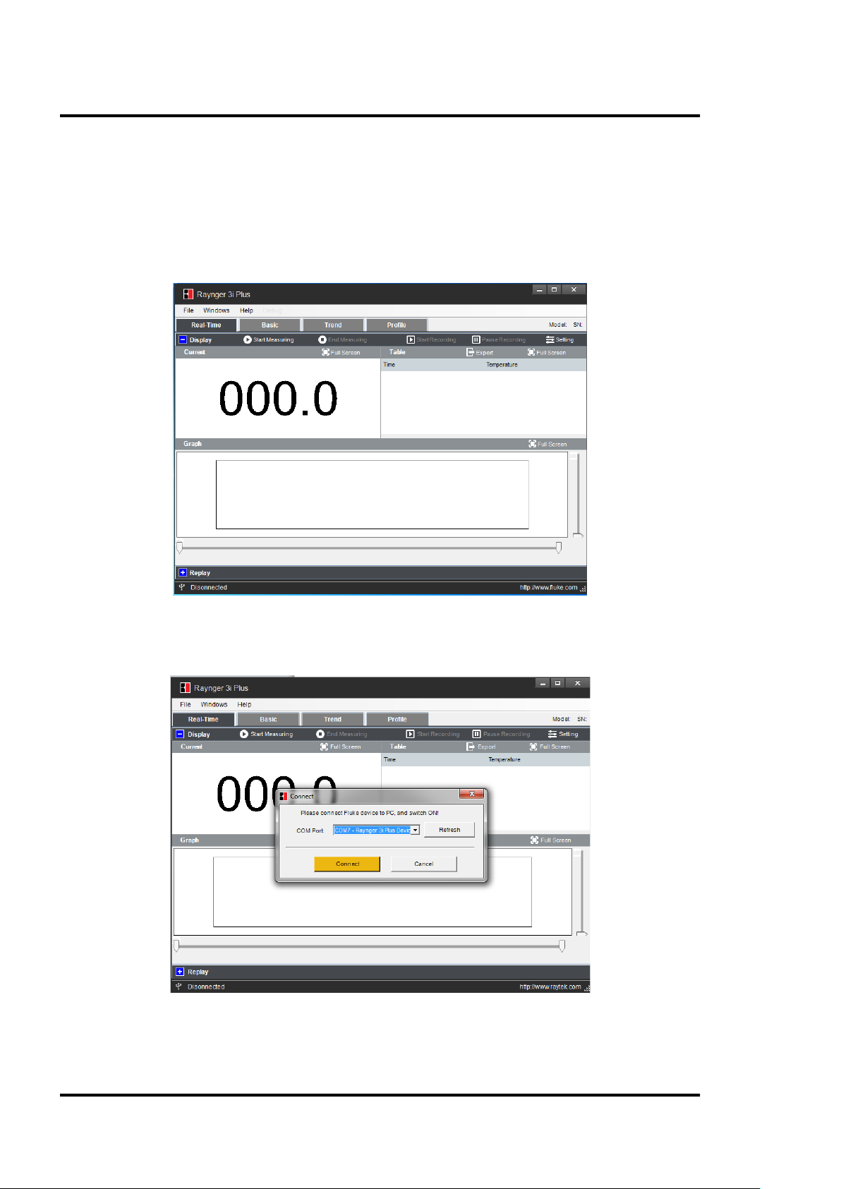
To establish communication between the instrument and the PC software, follow the steps below:
Step 1: Connect the instrument to the PC via USB
Step 2: Open the <File> menu
Figure 7: Open File
Step 3: Choose appropriate COM Port with Raynger 3i Plus Device and click <Connect>
Figure 8: COM Port Selection
Find Quality Products Online at: sales@GlobalTestSupply.com
34 Rev. A1 Jan 2015 3i Plus
www.GlobalTestSupply.com
Page 35

Windows Software
A simultaneous communication via USB and Bluetooth is not allowed!
Find Quality Products Online at: sales@GlobalTestSupply.com
3i Plus Rev. A1 Jan 2015 35
www.GlobalTestSupply.com
Page 36
Windows Software
7.5 Real-Time Data
7.5.1 Display
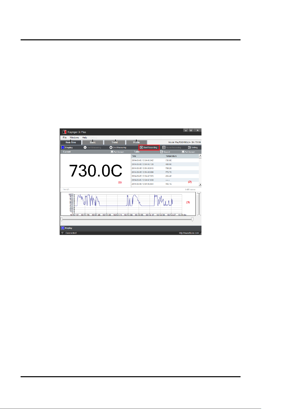
Under the real-time mode, the software provides multiple views. After pressing <Start Recording>,
you can enter real-time monitor mode, the trigger of the instrument is locked automatically. The
record list and the graph display will keep recording all test results until you press <Pause
Recording>.
• Display current temperature (1)
• Record list in a table (2)
• Real-time display curve as graph (3)
Figure 9: Display Window
7.5.2 Settings
When the instrument is connected to the PC, the software will read the instrument’s setting at first
and will add this information to the test report.
The user can also change these settings through the PC interface and upload to the instrument. Click
on the <Setting> button to launch the corresponding dialog box.
Find Quality Products Online at: sales@GlobalTestSupply.com
36 Rev. A1 Jan 2015 3i Plus
www.GlobalTestSupply.com
Page 37
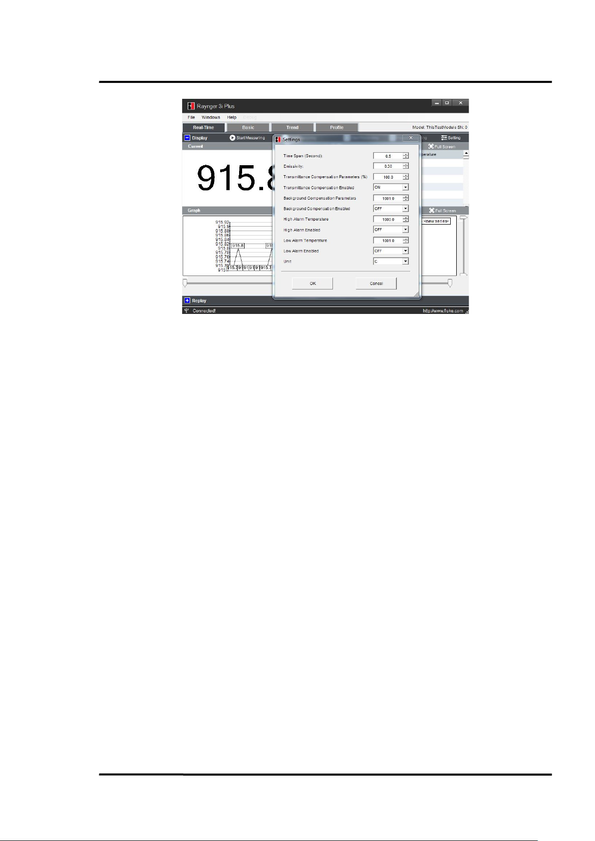
Figure 10: Settings Dialog
1
Time Span
2
Emissivity
3
Transmittance Compensation Parameters (%)
4
Transmittance Compensation Enabled
5
Background Compensation Parameters
6
Background Compensation Enabled
7
High Alarm Temperature
8
High Alarm Enabled
9
Low Alarm Temperature
10
Low Alarm Enabled
11
Unit
The user can change the following settings:
Windows Software
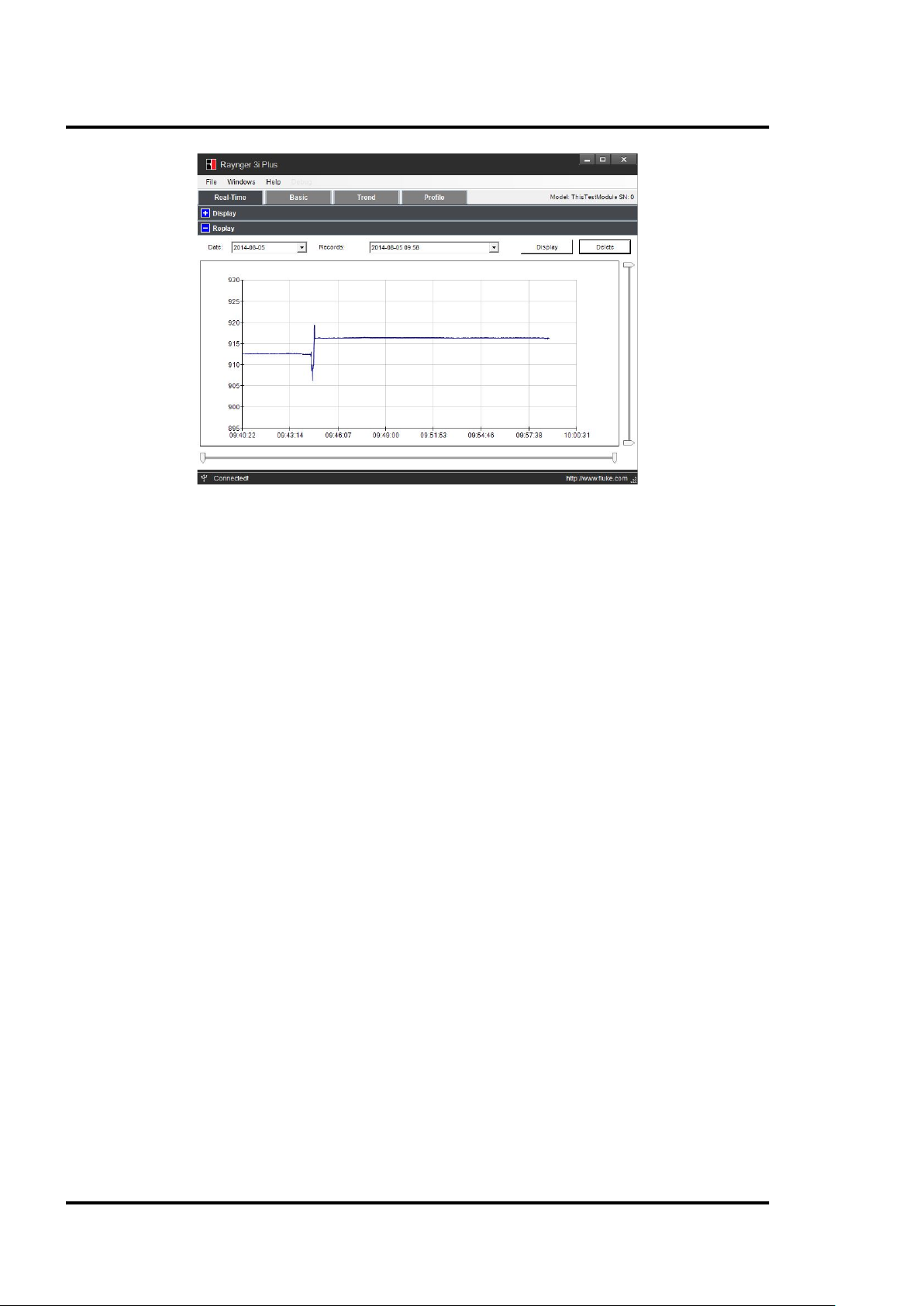
7.5.3 Replay
The user can replay the file recorded in real-time mode, search it according to date, and open the file
to review the trend change. The user can also export the saved curve into the .csv file format.
Find Quality Products Online at: sales@GlobalTestSupply.com
3i Plus Rev. A1 Jan 2015 37
www.GlobalTestSupply.com
Page 38
Windows Software
Figure 11: Replay Window
Find Quality Products Online at: sales@GlobalTestSupply.com
38 Rev. A1 Jan 2015 3i Plus
www.GlobalTestSupply.com
Page 39

Windows Software
7.6 Recorded Data
The recorded data is divided into three groups: <Basic test data>, <Trend data>, and<Profile test data>.
• <Basic test data> is the test data without dedicated settings. The user can record random
measurement data in this area with a maximum of 1,000 records.
• <Trend data> is saving data under trend mode, which should include three-screen data with
360 test values. The minimum interval for trend is 20 ms. In this mode, the user can capture
instant temperature changes. This data will be saved as a curve format. The user can review
the trend on the instrument, and the value of each test point by PC software.
Press <View> to review the trend picture, and the up and down arrows to choose each saved
trend data. The left and right arrows help in viewing the three screens for each piece of trend
data.
• <Profile test data> is the test data under the profile setting, which can save a maximum of
300 records. By using the load value of each profile, these test data have been divided by
group according to the profile setting in the PC software. The user can find the temperature
distribution status in one group. When starting the measurements, the user can easily recall a
profile instead of having the need to set each parameter individually such as emissivity or
temperature alarm thresholds.
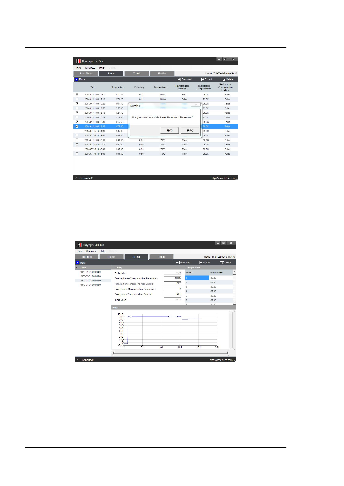
7.6.1 Basic Data
The user can import the test data under <Basic> measurement mode.
After pressing the <Download> button, the test data from the instrument will be read and appear in a
bivariate table format with time, temperature, emissivity, transmittance and background
compensation information.
Figure 12: Basic Window
There is a check box with each table row, so the user can choose the data to edit or export to a test
report with *. csv format.
Find Quality Products Online at: sales@GlobalTestSupply.com
3i Plus Rev. A1 Jan 2015 39
www.GlobalTestSupply.com
Page 40
Windows Software
7.6.2 Trend Data
Figure 13: Data Deletion
After the user has imported the trend test data from the instrument, the data will appear in a table
formatted with the point# and corresponding temperature value.
There is also a graphical area to display the trend data.
Figure 14: Trend Data
7.6.3 Profile Data
This feature provides a convenient method for the user to create settings through this function
according to their use case just before the measurements.
There are two locations to store the profile: <Local> and <Device>. The user can upload, edit, and
create the profile under the <Local> place, and download the device profile and device test data in
<Device> place.
Find Quality Products Online at: sales@GlobalTestSupply.com
40 Rev. A1 Jan 2015 3i Plus
www.GlobalTestSupply.com
Page 41

Figure 15: Profile Data
Windows Software
7.6.3.1 Local
Under this mode, in <Local> the user can create their own setting group with three level menus and
also with EMS, transmittance compensation, background compensation, high-temperature alarm, lowtemperature alarm setting, and laser and backlight enable or disable. For each profile, it will have a
profile code that includes the names of the first level menu, second level menu and test point number.
For example:
1. User named the first level “qwe,” the second level “asd,” and the test point is 20 pcs.
2. After these profiles were created, the user can upload these profiles to the instrument.
Find Quality Products Online at: sales@GlobalTestSupply.com
3i Plus Rev. A1 Jan 2015 41
www.GlobalTestSupply.com
Page 42

Windows Software
Figure 16: Local Profile
3. Before measurement, the user can call up this profile in the instrument:
7.6.3.2 Device
In <Device> mode, the user can download the existing profile from the instrument to the PC. Put the
mouse cursor on the 2
be found in this place, click <Import to Local> to perform editing both the profile structure and the
profile test data in <Local> place.
User can also delete the profile structure and profile test data in this place.
nd
level profile name, then click <Show Device Data>, afterwards all test data can
Find Quality Products Online at: sales@GlobalTestSupply.com
42 Rev. A1 Jan 2015 3i Plus
www.GlobalTestSupply.com
Page 43

Figure 17: Device Profile
Windows Software
The user can also download the test data with the <Export> function into a csv format.
Figure 18: Export Data to the PC
Find Quality Products Online at: sales@GlobalTestSupply.com
3i Plus Rev. A1 Jan 2015 43
www.GlobalTestSupply.com
Page 44

Windows Software
Profile
Name
Level 1
Profile
Name
Level 2
Test
Poin
t #
Tempera
ture
Value
Uni ts
Type
Record Time EMS
Transimit
tance
Compens
ation
Transimit
tance
Compens
ation
Backgro u
nd
Compens
ation
Backgro u
nd
Compens
ation
High
Alarm
Tempera
ture
High
Alarm
Enabled
Low
Alarm
Tempera
ture
Low Alarm
Enabled
SN
tes af d 1 768.2 C 2014/1/ 10 8:20 0. 1 FALSE 10% FALSE 25. 0C
2999.0C FALSE 699.0C FALSE 803
tes af d 1 768.5 C 2014/2/ 10 9:22 0. 1 FALSE 10% FALSE 25. 0C 2999.0C
FALSE
699.0C FALSE 803
tes af d 1
768.7 C 2014/ 3/10 10:25 0.1 FALSE 10% FALSE 25.0C 2999.0C FALSE 699. 0C
FALSE 803
tes af d 1 768.5
C 2014/4/ 10 8:23 0.1 FALSE 10% FALSE 25.0C 2999. 0C FALSE 699. 0C FALSE
803
tes af d 1 769.1 C 2014/5/ 10 8:22
0.1 FALSE 10% FALSE 25.0C 2999.0C FALSE 699.0C FALSE 803
tes af d 2 765.1 C 2014/1/ 10 9:09 0.25
FALSE
100% FALSE 25. 0C 2999. 0C FALSE 699. 0C FALSE 803
tes af d 2 765.4 C 2014/2/ 10 8:54 0.25 FALSE 100% FALSE
25.0C 2999.0C FALSE 699.0C FALSE 803
tes af d 2 765.7 C 2014/3/ 10 8:31 0.25 FALSE 100% FALSE 25.0C 2999.0C
FALSE 699. 0C FALSE 803
tes
afd 2 765.8 C 2014/ 4/10 8:39 0.25 FALSE 100% FALSE 25. 0C 2999.0C
FALSE
699.0C FALSE 803
tes af d 2
766.1 C 2014/5/ 10 8:29 0.25 FALSE 100% FALSE 25.0C 2999.0C FALSE 699. 0C
FALSE
803
The csv file will include the historical record of the same test points which is useful to the user to find
the change rule of each point. For example, in the table below, test point 1 and test point 2 all have 5
records with different times and the data shows the temperature is stable on these days.
Figure 19: Exemplary Historical Record
Find Quality Products Online at: sales@GlobalTestSupply.com
44 Rev. A1 Jan 2015 3i Plus
www.GlobalTestSupply.com
Page 45

Mobile App
8 Mobile App
The “Raytek 3i Plus” mobile app is a computer program designed to run on smartphones, tablet
computers and other mobile devices. The app requires the support of the iOS
system 7.0 or higher.
Please download the mobile app in the App Store by searching for its name, and install the app on
your mobile device.
After opening the Bluetooth switch on the instrument, the user can find the instrument on the mobile
device. Use the “Raynger 3i Plus” mobile app to monitor real-time temperature changes, download
Basic test data and Profile test data, and e-mail data in the .csv format.
Connecting the Instrument
Click on the <Raytek 3i Plus> icon; enter following <DataTemp Raynger 3i+> interface.
1. The APP can find the instrument automatically in the “Device” list.
2. User can change the device name to their favorite one and click the save icon, so it will be
shown when this instrument is connected next time.
3. After enter the APP, there are Real time; Basic log; Profile log options on the main screen.
1
mobile operating
Figure 20: Main Screens
8.1 Real Time View
The click on the <Real Time> button provides the following view.
1
iOS is a registered trademark of Apple Inc.
Find Quality Products Online at: sales@GlobalTestSupply.com
3i Plus Rev. A1 Jan 2015 45
www.GlobalTestSupply.com
Page 46

Mobile App
Figure 21: Real-Time Temperature View
By clicking on the camera icon on the upper-right corner, the user can take a photo from the field.
By clicking on the <Send> icon, the user could e-mail the photo and data.
Figure 22: Real-Time E-Mail
8.2 Basic Test Data
By clicking on the <Basic Test Data> button, the user can download the recorded Basic Data into the
unit.
This place permits the user to download Basic test data in several phases (100 pcs data in one phase).
So if there are plenty of test data, after the first 100 pcs has been finished download, please click the
continue button on the screen to keep on downloading the remained data.
Notes:
1. The download data won’t be stored in iPhone, so if user left this page and enter again, the
APP will download the test data again automatically.
Find Quality Products Online at: sales@GlobalTestSupply.com
46 Rev. A1 Jan 2015 3i Plus
www.GlobalTestSupply.com
Page 47

Mobile App
2. To ensure the download process more smooth, please do not use the unit perform testing
during data download period.
Figure 23: Basic Test Data Download
8.2.1 Data Review
After completing the download, a list of the recorded dates and times will be displayed, see left figure
below.
By clicking on the desired data set, the temperature and the relative settings of the reading will be
shown, see right figure below.
Figure 24: Basic Log
Clicking on the e-mail icon in the upper right corner enables details to be emailed.
Find Quality Products Online at: sales@GlobalTestSupply.com
3i Plus Rev. A1 Jan 2015 47
www.GlobalTestSupply.com
Page 48

Mobile App
Figure 25: Basic Log E-Mail Sending
For sending multiple sets of data via e-mail, click on the
below.
By clicking the e-mail icon in the upper right corner the selected test data can be sent, see right
figure below.
Figure 26: Basic Log – Multiple Data Sets
to the left of the list of items, see left figure
8.2.2 Data Review by Time
By clicking on the time input box in the upper left corner, a dialog box opens to select the starting
time/data for the recorded data sets.
Find Quality Products Online at: sales@GlobalTestSupply.com
48 Rev. A1 Jan 2015 3i Plus
www.GlobalTestSupply.com
Page 49
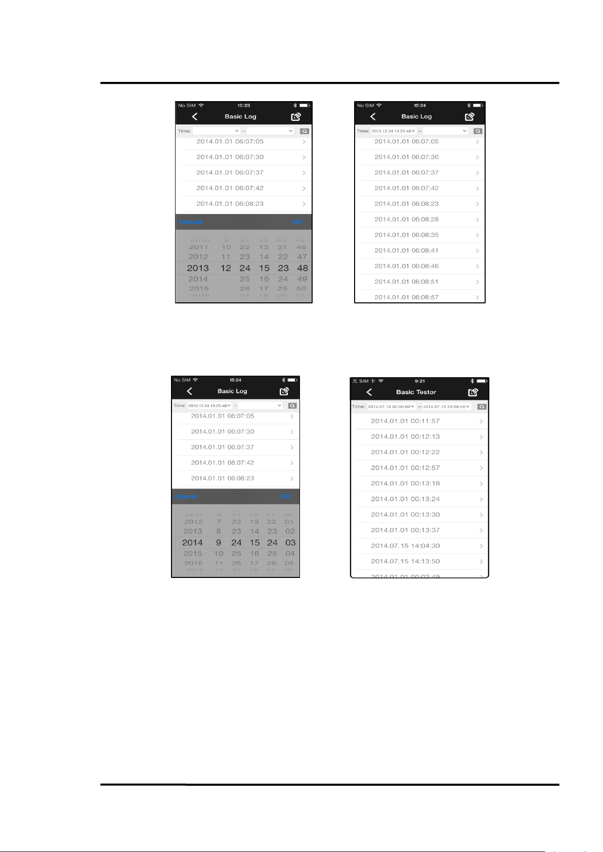
Mobile App
Figure 27: Basic Log – Data Sets at the desired Starting Time
By clicking on the time input box in the upper right corner, a dialog box opens to select the end
time/data for the recorded data sets.
Figure 28: Basic Log – Data Sets at the desired End Time
By clicking on the <Finding> icon, the selected items will be displayed as follows:
Find Quality Products Online at: sales@GlobalTestSupply.com
3i Plus Rev. A1 Jan 2015 49
www.GlobalTestSupply.com
Page 50

Mobile App
Figure 29: Basic Log Download – Selected Data Items
By clicking on the e-mail icon in the upper right corner, the selected data can be sent by e-mail.
Figure 30: Basic Log Data E-Mail
8.3 Profile Test Data
By selecting the <Profile Test Data> icon, the user can download the Profile Test data from the unit.
Clicking on each item provides the detail data for that group.
Note:
1. To ensure the download process more smooth, please do not use the unit perform testing
during data download period.
Find Quality Products Online at: sales@GlobalTestSupply.com
50 Rev. A1 Jan 2015 3i Plus
www.GlobalTestSupply.com
Page 51
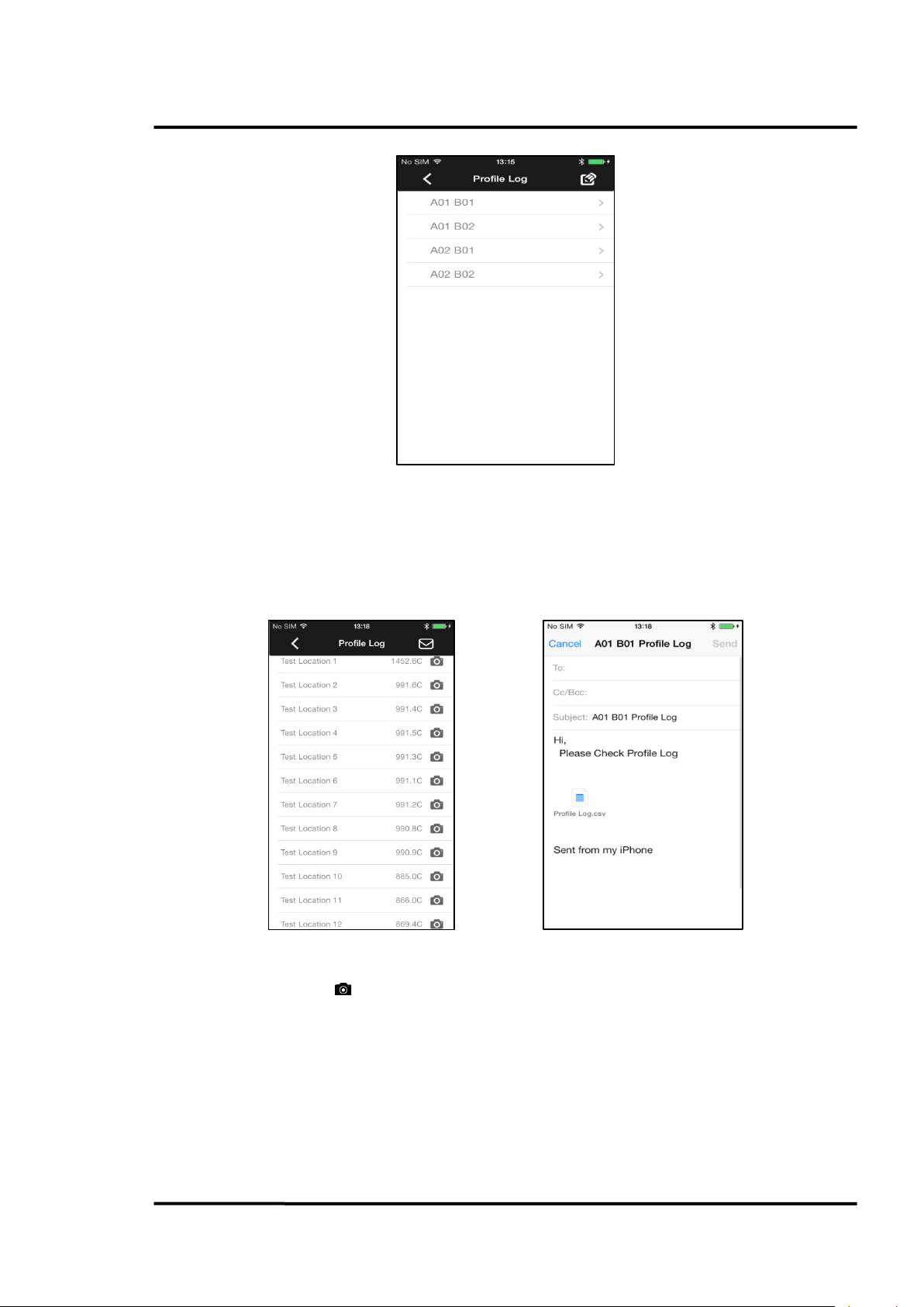
Figure 31: Profile Log Data
Mobile App
For sending multiple sets of data, such as<A01 B01>, click the
left figure below.
By clicking on the e-mail icon in the upper right corner the selected test data can be sent, see right
figure below.
Figure 32: Profile Test Data – E-Mail Sending
on the left side of the list of items, see
By clicking on the camera icon on the upper-right corner, the user can take a photo from the field.
By clicking on the e-mail icon in the upper right corner the selected test data can be sent.
Find Quality Products Online at: sales@GlobalTestSupply.com
3i Plus Rev. A1 Jan 2015 51
www.GlobalTestSupply.com
Page 52
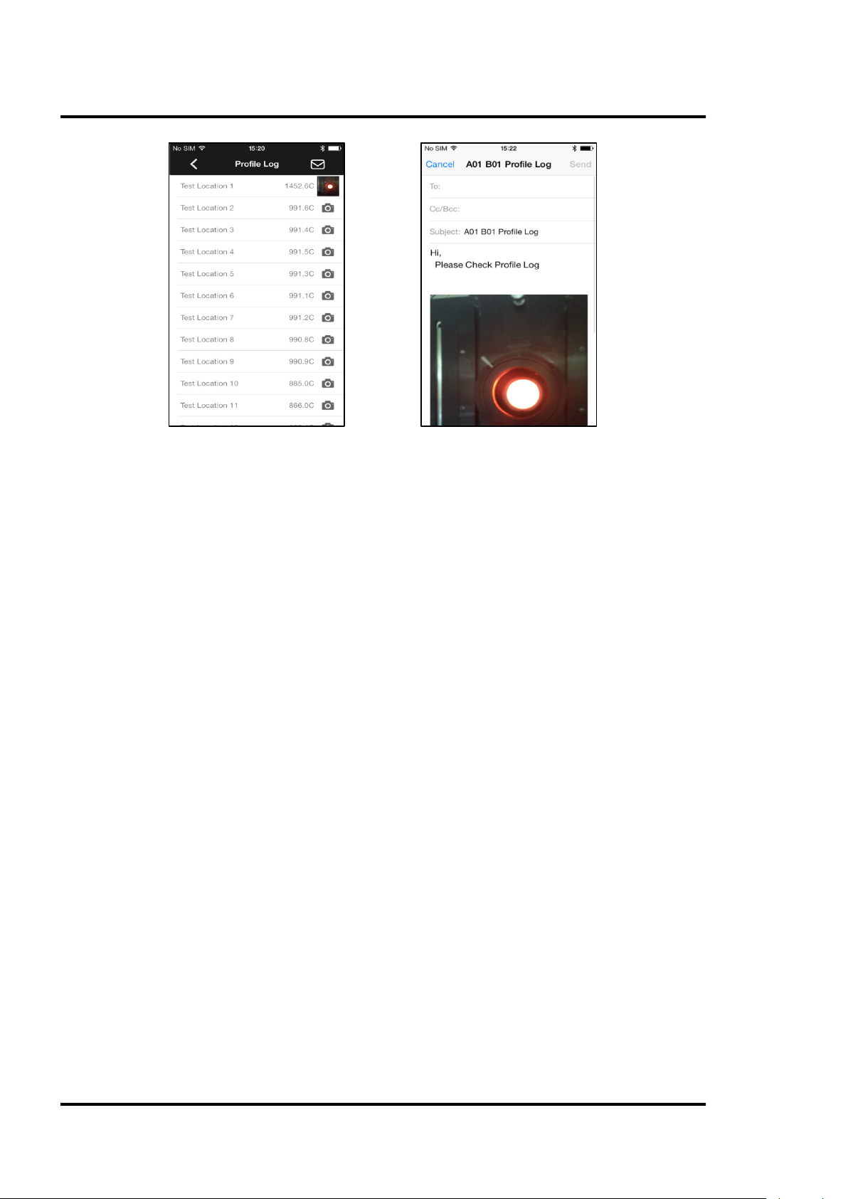
Mobile App
Figure 33: Profile Test Data with Photos Attached
Find Quality Products Online at: sales@GlobalTestSupply.com
52 Rev. A1 Jan 2015 3i Plus
www.GlobalTestSupply.com
Page 53

Maintenance
Symptom
Probable Cause
Solution
Wrong Emissivity
Correct Emissivity Setting
Wrong Background Temperature
Compensation
Correct Background Temperature
Compensation Setting
Wrong Transmittance
Correct Transmittance Setting
Adjust Field of View via Laser Indication or
Scope Red Point
Obstructed Field of View
Remove Obstruction
Dirty Lens
Clean Lens
Move the instrument away from the hot
temperature source
Wrong High Temperature Alarm
Correct High Temperature Alarm Setting
Wrong Low Temperature Alarm
Correct Low Temperature Alarm Setting
Battery Symbol Blank
Insufficient Battery Level
Charge Battery
No Trigger/Button
Unload Battery, Disconnected USB Cable
Reload Battery
Trigger/Button Damage
Contact After-Sale Service
Battery Level is too low
Charge Battery
Invalid Battery
Change to a new Battery
LCD damage
Contact Service
No LCD Backlight
LCD damage
Contact Service
No Scope Red-point
Scope damage
Contact Service
Ambient Temperature exceeds Operation
Temperature range
Laser damage
Contact Service
Wrong Cable
Use the special USB charge cable
Battery/Cable damage
Change to a new Battery/Cable
USB interface
Contact Service
Wrong Cable
Use the special USB cable
Wrong PC software
Reinstall the latest PC software
USB interface damage
Contact Service
9 Maintenance
Our sales and customer service representatives are always at your disposal for questions regarding
applications, calibration, repair, and solutions to specific problems. Please contact your local sales
representative if you need assistance. In many cases, problems can be solved over the telephone. If
you need to return equipment for servicing, calibration, or repair, please contact our Service
Department before shipping. Phone numbers are listed at the beginning of this document.
9.1 Troubleshooting
Erroneous Temperature
Inaccurate Field of view
LCD Backlight Red and
Buzzer Sounds
Response
No LCD Display
No Laser
Unable to Charge Battery
Via Cable
Unable to communicate
with PC Via Cable
Nose Too Hot
Use it in the operation temperature range
Unable to Communicate
with iPhone Via Bluetooth
Find Quality Products Online at: sales@GlobalTestSupply.com
3i Plus Rev. A1 Jan 2015 53
Wrong iPhone software Reinstall the latest iPhone App
Bluetooth damage Contact Service
Table 5: Troubleshooting
www.GlobalTestSupply.com
Page 54
Maintenance
Do not use any ammonia, or cleaners with ammonia, bleach, acids, or strong bases. This
, do NOT submerge it in water. Do not use abrasive
9.2 Lens Cleaning
The user should periodically clean the instrument’s front window.
A dirty front window (lens) can cause temperature measurement errors. The window is fragile, and
care should be taken when cleaning it to prevent scratching. Use camera lens or eye glass tissues to
clean the window.
Periodic cleaning can be done by completing one or more of the following in one of the following
ways:
• Blow loose particles off the front window with clean compressed air.
Note: Unfiltered compressed air, as well as user’s own breath, can cause condensation on the
front window, which can trap dust particles instead of removing them.
• Gently brush off particles with a soft camelhair brush.
• Thicker contaminants can be cleaned with water and a camera lens tissue.
• Fingerprints and grease can be removed either with isopropyl alcohol, Ethanol, Xylene,
Acetone, or Kodak
lens tissue until user see colors on the surface, then allow to air dry. Do not wipe the surface
dry, as this may scratch the surface.
Can cause severe damage to the front window!
®
Lens Cleaner. Apply to the front window, and wipe gently with a camera
9.3 Housing Cleaning
The user should periodically clean the instrument’s housing.
To clean the instrument’s housing, simply use soap and water or a mild commercial cleaner. Wipe
with a damp sponge or soft rag. Use a soft rag to gently wipe the display.
To avoid damaging the instrument
Cleaners will damage the case!
9.4 Laser Fault
If the laser (laser models only) does not operate properly, call the supplier of the instrument. DO NOT
open the instrument’s main housing.
Find Quality Products Online at: sales@GlobalTestSupply.com
54 Rev. A1 Jan 2015 3i Plus
www.GlobalTestSupply.com
Page 55
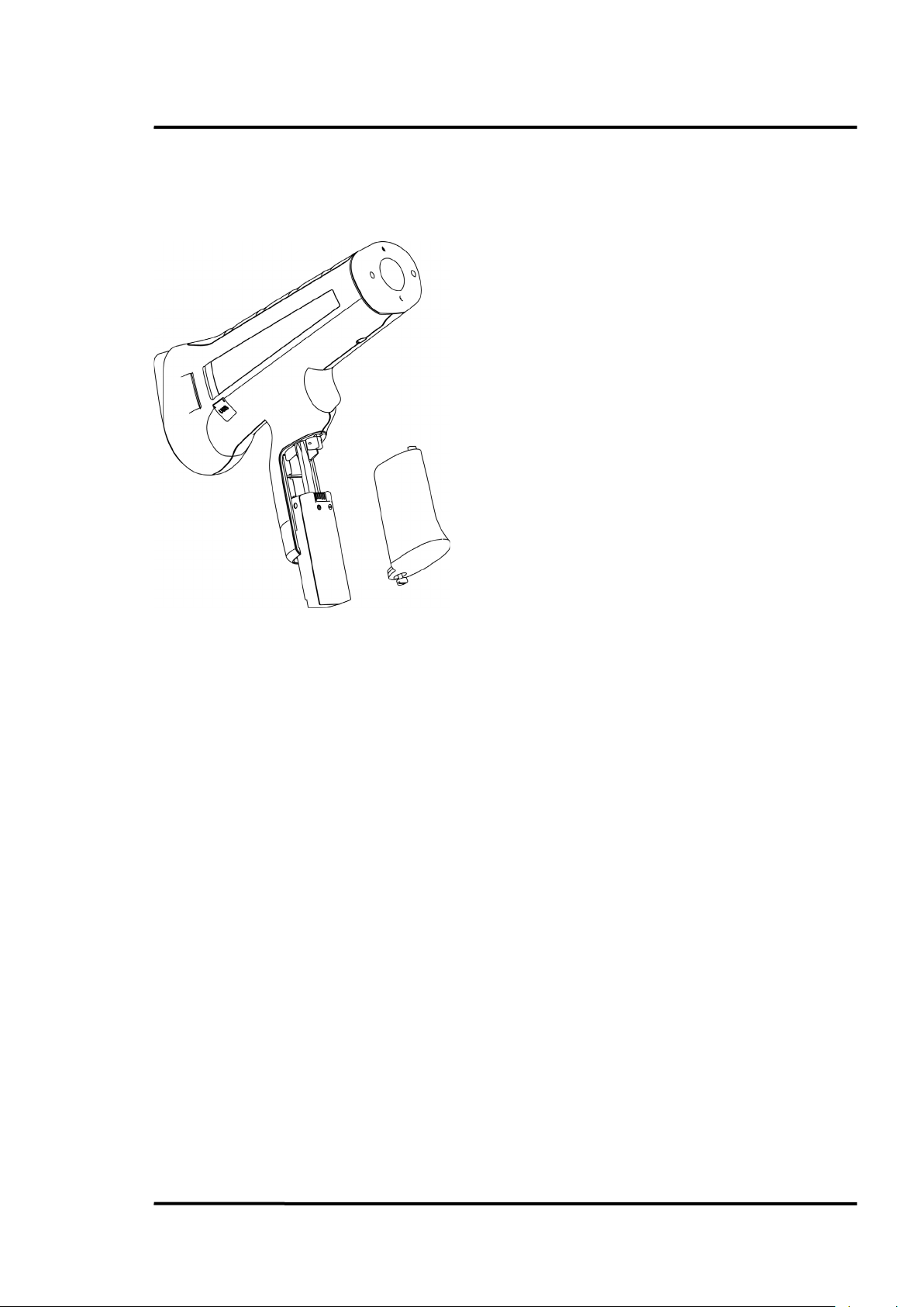
9.5 Battery Exchange
1. Unscrew the battery door.
For exchanging the battery, follow the steps given below.
2. Remove the battery door bolt.
3. Slide the battery along the lead rail.
Maintenance
Figure 34: Removing the Battery
Find Quality Products Online at: sales@GlobalTestSupply.com
3i Plus Rev. A1 Jan 2015 55
www.GlobalTestSupply.com
Page 56

Appendix
Emissivity at 1 µm for Non-Metals
Asbestos
0.9
Ceramic
0.4
Concrete
0.65
Carbon
Unoxidized
0.8-0.95
Graphite
0.8-0.9
10 Appendix
10.1 Determination of Emissivity
Emissivity is a measure of an object’s ability to absorb and emit infrared energy. It can have a value
between 0 and 1.0. For example, a mirror has an emissivity of 0.1, while the so-called “Blackbody“
reaches an emissivity value of 1.0. If a higher than actual emissivity value is set, the output will read
low, provided the target temperature is above its ambient temperature. For instance, if the set value is
0.95 and the actual emissivity is 0.9, the temperature reading will be lower than the true temperature.
An object’s emissivity can be determined by one of the following methods:
1. Determine the actual temperature of the material using an RTD (PT100), a thermocouple, or any
other suitable method. Next, measure the object’s temperature and adjust emissivity setting until
the correct temperature value is reached. This is the correct emissivity for the measured material.
2. If possible, apply flat black paint to a portion of the surface of the object. The emissivity of the
paint must be above 0.98. Next, measure the temperature of the painted area using an emissivity
setting of 0.98. Finally, measure the temperature of an adjacent area on the object and adjust the
emissivity until the same temperature is reached. This is the correct emissivity for the measured
material.
10.2 Typical Emissivity Values
The following table provides a brief reference guide for determining emissivity and can be used when
one of the above methods is not practical. Emissivity values shown in the table are only approximate,
since several parameters may affect the emissivity of a material. These include the following:
1. Temperature
2. Angle of measurement
3. Geometry (plane, concave, convex)
4. Thickness
5. Surface quality (polished, rough, oxidized, sandblasted)
6. Spectral range of measurement
7. Transmissivity (e.g., thin films, plastics)
Table 6: Typical Emissivity Values (Metals)
Table 7: Typical Emissivity Values (Non-Metals)
Find Quality Products Online at: sales@GlobalTestSupply.com
56 Rev. A1 Jan 2015 3i Plus
www.GlobalTestSupply.com
Page 57

Metals
Material
1 µm
1.6 µm
Aluminum
Unoxidized
0.1-0.2
0.02-0.2
Oxidized
0.4
0.4
Alloy A3003,
Oxidized
0.4
Roughened
0.2-0.8
0.2-0.6
Polished
0.1-0.2
0.02-0.1
Brass
Polished
0.1-0.3
0.01-0.05
Burnished
Oxidized
0.6
0.6
Chromium
0.4
0.4
Oxidized
Copper
Polished
0.03
Roughened
0.05-0.2
Oxidized
0.2-0.8
0.2-0.9
Gold
0.3
0.01-0.1
Haynes
Alloy
0.5-0.9
0.6-0.9
Inconel
Oxidized
0.4-0.9
0.6-0.9
Sandblasted
0.3-0.4
0.3-0.6
polished
0.2-0.5
0.25
Iron
Oxidized
0.4-0.8
0.5-0.8
Unoxidized
0.35
0.1-0.3
Rusted
0.6-0.9
Molten
0.35
0.4-0.6
Iron, Cast
Oxidized
0.7-0.9
0.7-0.9
Unoxidized
0.35
0.3
Molten
0.35
0.3-0.4
Iron, Wrought
Dull
0.9
0.9
Lead
Polished
0.35
0.05-0.2
Rough
0.65
0.6
Oxidized
0.3-0.7
Magnesium
0.3-0.8
0.05-0.3
Mercury
0.05-0.15
Molybdenum
Oxidized
0.5-0.9
0.4-0.9
Unoxidized
0.25-0.35
0.1-0.35
Appendix
Emissivity
Find Quality Products Online at: sales@GlobalTestSupply.com
3i Plus Rev. A1 Jan 2015 57
www.GlobalTestSupply.com
Page 58

Appendix
Metals
Material
1 µm
1.6 µm
Monel (Ni-Cu)
0.3
0.2-0.6
Oxidized
Nickel
Oxidized
0.8-0.9
0.4-0.7
Electrolytic
0.2-0.4
0.1-0.3
Platinum
Black
0.95
Silver
0.02
Steel
Cold-Rolled
0.8-0.9
0.8-0.9
Ground Sheet
Polished Sheet
0.35
0.25
Molten
0.35
0.25-0.4
Oxidized
0.8-0.9
0.8-0.9
Stainless
0.35
0.2-0.9
Tin (Unoxidized)
0.25
0.1-0.3
Titanium
Polished
0.5-0.75
0.3-0.5
Oxidized
0.6-0.8
Tungsten
Polished
0.35-0.4
0.1-0.3
Zinc
Oxidized
0.6
0.15
Polished
0.5
0.05
Emissivity
Table 8: Typical Emissivity Values
To optimize surface temperature measurements, consider the following guidelines:
• Determine the object emissivity using the instrument, which is also to be used for
measurements.
• Avoid reflections by shielding the object from surrounding temperature sources.
• For higher temperature objects use instruments with the shortest wavelength possible.
• For translucent materials such as plastic foil or glass, ensure that the background is uniform
and lower in temperature than the object.
• Hold instrument perpendicular to surface whenever emissivity is less than 0.9. In all cases, do
not exceed angles more than 30 degrees from incidence.
• For 1M and 2M models, avoid measurements in high ambient light conditions.
Find Quality Products Online at: sales@GlobalTestSupply.com
58 Rev. A1 Jan 2015 3i Plus
www.GlobalTestSupply.com
Page 59

Appendix
10.3 Compliance Standards
IEC 61010-1 Safety Requirements for Electrical Equipment for Measurement, Control, and Laboratory
Use -- Part1: General Requirements
IEC 60529 Degrees of Protection Provided by Enclosures (IP Code)
EN 61326-1 Electrical Equipment for Measurement, Control and Laboratory Use – EMC
Requirements --- Part1 : General Requirements
EN 61326-2-2 Electrical Equipment for Measurement, Control and Laboratory Use --EMC
Requirements – Part 2-2 : Particular Requirements – Test Configurations, Operational Conditions and
Performance Criteria for Portable Test, Measuring and Monitoring Equipment Used in Low-Voltage
Distribution Systems
CISPR 11 Industrial, Scientific and Medical Equipment –Radio-Frequency Disturbance
Characteristics –Limits and Methods of Measurement
EN 60825-1 Safety of Laser Products – Part 1 : Equipment Classification and Requirements
FDA 21 CFR 1040.10, 1040.11 with Laser Notice 50 Performance Standards for Light-Emitting
Products ---Laser Products
IEC 62133 Secondary Cells and Batteries Containing Alkaline or other non-acid Electrolytes — Safety
Requirements for Portable Sealed Secondary Cell, and for Batteries Made from Them, for Use in
Portable Applications
UN 38.3 Recommendations on the Transport of Dangerous Goods, Manual of Test and Criteria –
Lithium Batteries
EN 300328 Electromagnetic Compatibility and Radio Spectrum Matters (ERM); Wideband
Transmission System; Data Transmission Equipment Operating in the 2.4 GHz ISM Band and Using
Wide Band Modulation Techniques; Harmonized EN Covering Essential Requirements under Article
3.2 of the R&TTE Directive
Find Quality Products Online at: sales@GlobalTestSupply.com
3i Plus Rev. A1 Jan 2015 59
www.GlobalTestSupply.com
 Loading...