

Raytec SPZ-WL84-EM, SPX-WL84-STD, SPZ-WL84-STD, SPX-WL168-STD, SPZ-WL168-STD Installation Manual
...Page 1

SPX/SPZ
SPARTAN
Linear Range - Installation Guide
CML14ATEX3119 & IEC Ex CML15.0001
CML15ATEX4138 & IEC Ex CML15.0068
CML16ATEX1130 & IEC Ex CML16.0052
This installation guide provides instructions for installing SPARTAN series of explosion
protected linear luminaires.
Text in italics is specic for emergency variants.
Overview
1 Safety Instructions
2 Installation
3 Maintenance
4 Technical Specication
5 Declaration of Conformity
Important information
The SPARTAN series of explosion protected luminaires are specialist devices, certied for
use in specic operating environments.
The units must be installed in accordance with these instructions, must be correctly certied
for the specic operating environment and must be installed by suitably qualied personnel.
If you have any queries about the installation or the certication of the unit – please contact
Raytec for immediate assistance and advice.
910-M-0284 Rev A
Page 2
1. Safety instructions
1. Read this leaet carefully before commencing to install the SPARTAN unit and retain it
for future use. Installation can only be carried out by suitably qualied personnel.
2. Check the certication to ensure that the hazardous zone, mains supply, ambient
temperature present and ‘T’ rating are is suitable for the environment the unit is being
installed in.
3. If the SPARTAN unit is to be installed in areas of high vibration, please consult with
Raytec.
4. The SPARTAN unit housing is constructed from marine grade aluminium and
polycarbonate outer optic. The end user must ensure that these materials are suitable
for the environment the SPARTAN unit will be installed in; Zone 1 or Zone 2 Hazardous
areas.
Plastic components may be cleaned with water containing a small amount of detergent,
followed by a clean water wash. Chemicals/ oils that come into contact with plastic
parts may cause stress cracking and premature component failure.
5. Check certication nameplate on cover of luminaire to ascertain type of threaded cable
entry on the luminaire. Select suitably certied ATEX/IEC Ex cable glands and stopper
plugs, these must be parallel thread, have a minimum of 5 full thread engagement and
be of a medium/ne tolerance to ISO965-1 and ISO965-3. The cable entry devices
selected must maintain the IP rating of the luminaire
o
6. The incoming mains cable should not exceed a temperature rise of 27
ambient conditions; select suitable cable.
C above the
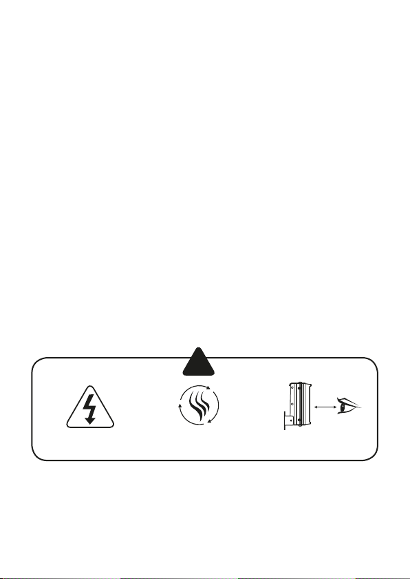
Isolate mains before
removing cover
2 www.raytecled.com UK / Europe Tel: +44 (0) 1670 520055
!
Install in a well
ventilated area
1.5m
Do not continually
stare at lamp
Americas Tel: +1 613 270 9990
Page 3
2. Installation
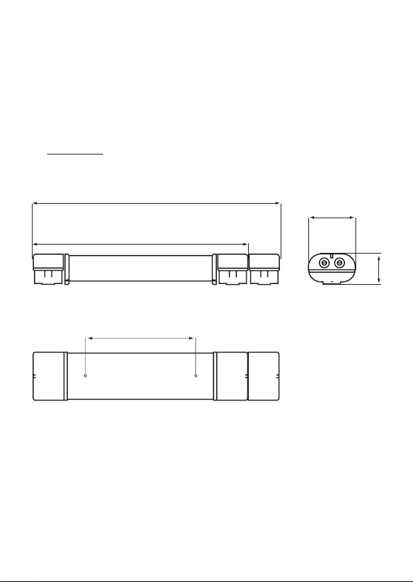
Mounting SPARTAN Unit
1. To meet the requirements of certication a MINIMUM of 2 xing points must be used,
the xing points must be suitable for the conditions of use.
2. The rear of the unit has 3 blind sets of M8/M6 xing points, a full range of mounting
accessories are available including a range of pole clamps, ceiling mount brackets,
various wall mount brackets, outreach bracket and chain mount eyelets. Please consult
www.raytecled for further details
1414 FOR WL168 EMER
775 FOR WL84 STD AND EMER
1295 FOR WL168 STD
1635 FOR WL168-1500 STD
400 FOR WL84
700 FOR WL168/WL168-1500
3. When installing the SPARTAN luminaire vertically where possible, the cable glands
should be kept to the bottom of the luminaire.
174
108
Americas Tel: +1 613 270 9990
3www.raytecled.comUK / Europe Tel: +44 (0) 1670 520055
Page 4
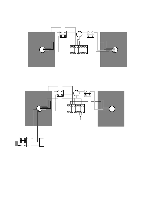
PSU
Typical wiri ng diagram - Standard Variants
EARTH TO SCREW
WHITE
WHITE/RED
GREEN
BROWN
BLUE
TO LED's
N E L1 L2
PSU
BROWN
BLUE
WHITE
RED
PSU
BLACK
BLACK
RED
FUSE
Wire the Mains cable into the terminal block. Provision has been made for this and identied
as the E (Earth), L1 (Live switched), L2 (Live permanent) and N (Neutral) terminals. There are
two pairs of contacts for each of these to facilitate a mains cable that can be looped in and
out of the unit, an identical terminal block is also available at the other end of the luminaire
to allow the unit to be through wired. The L2 terminals on a standard unit is not electrically
connected but allows them to be used on the same circuits as emergency luminaires.
4. Installer should earth the unit separately – an internal and external earth point are
provided as standard at each end of the luminaire
BATTERY
RED
4 www.raytecled.com UK / Europe Tel: +44 (0) 1670 520055
Typical wiri ng diagram - Emergency Variants
GREEN
EARTH TO SCREW
WHITE
WHITE/RED
GREY
BROWN
BLUE
TO LED's
N E L1 L2
REMOVE LINK IF 4-CORE CABLE USED
PSU
BROWN
BLUE
WHITE
RED
Americas Tel: +1 613 270 9990
Page 5

5. Connect wires to mains supply.
6. If the unit is opened for any reason, disconnect mains – On emergency luminaires
there may be more than one mains supply
7. All SPARTAN luminaires have terminal blocks suitable for looping 4mm2 cable,
only one cable should be connected to each terminal block connection
8. The battery fuse is located in the compartment that contains the battery, the fuse
is disconnected after nal manufacturing testing. When installing the linear the
battery fuse will need to be reconnected and the unit charged for 24 hours and then
discharged (repeated 3 times) to bring the battery up to peak capacity. (Unless an
‘EMX’ intelligent emergency variant – see notes below)
9. If a 4 core cable is used on emergency luminaires – L1, L2, N and E the link cable
at the front of the terminal block between L1 and L2 should be removed
10. During emergency operation the light output and duration will be determined by the
variant purchased
Spartan Intelligent Emergency Operation Guide
Operation
The light tting will carry out the following function automatically after installation:
• Commissioning Cycle
• Function test
• Self-test
A tri-colour LED indicator displays the light tting status. The indication colours are shown
in table 1.
a. Commissioning Cycle
• Starts automatically 24 hours after installation.
• 3 charge/discharge cycles to maintain battery’s full capacity.
• Battery is charged for 24 hours before each discharge cycle.
• No need for manual commissioning
b. Function Test
• Carried out every 7 days.
• Checks the function of the battery, lamp and power supply.
• Lasts for few minutes only.
Americas Tel: +1 613 270 9990
5www.raytecled.comUK / Europe Tel: +44 (0) 1670 520055
Page 6

c. Self-test
• Carried out at a random time every 3 month.
• Checks the battery’s capacity and lamp’s condition.
• Performs self-recovery for the battery if not at peak capacity.
• Is carried out at 100% load
• Discharges only 2/3 of the battery’s capacity.
LED indication
LED Indication Condition
Blinking amber Commissioning
Static Amber
Blinking Red
No light Emergency mode activated
Static Green Battery charged and PSU OK
Function Test
Self-test
Battery defective/Fuse blown
PSU error
Battery not at peak capacity
Light engine failure
Notes
• The luminaire will switch off momentarily (<0.5sec) during the transition between a
test and normal operation.
• If a test was interrupted by a mains failure, the test will be halted, and the unit will
enter emergency mode. Once the mains supply is back, the unit will allow 24 hours
to recharge the battery before continuing the tests.
• The self-test is carried out at a random time to eliminate the possibility of having more
than one unit undergoing the test at the same time.
6 www.raytecled.com UK / Europe Tel: +44 (0) 1670 520055
Americas Tel: +1 613 270 9990
Page 7

3. Maintenance
1. It is essential that all SPARTAN units are maintained in accordance with the
requirements of the EN60079-17 standard: (Electrical apparatus for explosive gas
atmospheres – other than mines).
2. IMPORTANT. No modications are permitted to the unit, all spare parts must be
purchased from the manufacturer, unauthorized modications or spare parts will
invalidate certication and make the equipment dangerous.
3. Isolate the SPARTAN unit from the mains supply and allow to cool before carrying out
any maintenance work.
• For Emergency variants, battery must be isolated/ connected when a hazardous
environment is NOT present prior to carrying out any maintenance work.
4. In the unlikely event of a number of LED’s failing, the light engine assembly must
be replaced. This is achieved by removing the outer polycarbonate cover and then
releasing the M3 bolts that hold the LED assembly in place, disconnect the white and
red/white cable to the power supply and pull the light engine PCB clear. Re tting a
light engine is a reversal of the above procedure.
• For emergency variants, battery must be isolated/ connected when a hazardous
environment is NOT present prior to carrying out any maintenance work.
5. The unit has either 1 or 2 independent power supplies located in the terminal chamber
covers, in the event that a power supply needs to be replaced the terminal chamber cover
should be removed, the cables disconnected and the dog clip can then be detached
from the cover. Fitting a new power supply is a reversal of the above procedure.
6. Disposal of packaging, SPARTAN unit and old LED assemblies/power supplies should
be carried out in accordance with national regulations.
Protection Concepts
CML14ATEX3119 or IEC Ex CML15.0001
Standard variants
II 2 GD Ex e mb op is IIC T4 Gb
Ex tb op is IIIC T75°C Db
-40°C to +55°C
CML15ATEX4138 or IEC Ex CML15.0068
Standard variants
II 3 GD Ex nA mc op is IIC T4 Gc
Ex tc op is IIIC T80°C Dc
-40°C to +60°C
CML16ATEX1130 or IEC Ex CML16.0052
Standard variants
II 2 D Ex tb op is IIIC T80°C Db
-40°C to +60°C
Americas Tel: +1 613 270 9990
Emergency variants
II 2 GD Ex e mb op is IIC T4 Gb
Ex tb op is IIIC T76°C Dc
-20°C to +50°C
Emergency variants
II 3 GD Ex nA mc op is IIC T4 Gc
Ex tc op is IIIC T75°C Dc
-20°C to +50°C
Emergency variants
II 3 D Ex tb op is IIIC T76°C Db
-20°C to +50°C
7www.raytecled.comUK / Europe Tel: +44 (0) 1670 520055
Page 8

4. Technical Specication
WL84-STD WL84-EM WL168-STD WL168-EM
Input Voltage 110-254V AC/DC
Input Current (230Vac, full load) 0.15A 0.3A
Consumption 35W 65W
Power Factor (230Vac, full load) >0.97
Mains Frequency 50/60Hz
Inrush Current (I
Total Harmonic Distortion (230Vac, full load) <10%
ATEX and IECEx Rating See below
Inrush Current Typical Curve
Ipeak
@50%) 20A, ∆t < 300µs 28A, ∆t < 300µs
peak
IP Rating IP66/67
Weight (std) 6Kg 7Kg 9Kg 10Kg
Dimensions See previous pages for line diagrams
Twidth
8 www.raytecled.com UK / Europe Tel: +44 (0) 1670 520055
Americas Tel: +1 613 270 9990
Page 9

Max number of ttings allowed per MCB
(Based on 230V)
MCB Type Rating
B 10A 11 10 5 4
B 16A 17 15 8 7
B 20A 25 22 12 11
B 25A 35 32 16 15
C 10A 24 20 11 10
C 16A 34 28 16 15
C 20A 49 44 23 20
C 25A 58 55 28 25
SPZ/SPX-WL84
SPZ/SPX-WL84EMSPZ/SPX-WL168
STD
STD
SPZ/SPX-WL168
EM
Americas Tel: +1 613 270 9990
9www.raytecled.comUK / Europe Tel: +44 (0) 1670 520055
Page 10

Declaration Of Conformity
With The Atex Directive 2014/34/EU
Raytec Ltd. declares under our sole responsibility that the product(s) listed below
conform with the relevant provisions of directive 2014/34/EU of 20
Manufacturer Raytec Ltd
Description
of Equipment
Notied Bodies Sira Certication Services (0518)
Certicate
numbers
CML14ATEX3119 or IEC Ex CML15.0001
Standard variants
II 2 GD Ex e mb op is IIC T4 Gb
Ex tb op is IIIC T75°C Db
-40°C to +55°C
CML15ATEX4138 or IEC Ex CML15.0068
Standard variants
II 3 GD Ex nA mc op is IIC T4 Gc
Ex tc op is IIIC T80°C Dc
-40°C to +60°C
Unit 15, Wansbeck Business Park
Rotary Parkway
Ashington
Northumberland
NE63 8QW
United Kingdom
Spartan range of linear luminaires – standard and emergency
Unit 6,
Hawarden Industrial Park
Hawarden
Deeside
CH5 3US
CML14ATEX3119 & IEC Ex CML15.0001
CML15ATEX4138 & IEC Ex CML15.0068
CML16ATEX1130 & IEC Ex CML16.0052
Emergency variants
II 2 GD Ex e mb op is IIC T4 Gb
Ex tb op is IIIC T76°C Dc
-20°C to +50°C
Emergency variants
II 3 GD Ex nA mc op is IIC T4 Gc
Ex tc op is IIIC T75°C Dc
-20°C to +50°C
th
April 2016
10 www.raytecled.com UK / Europe Tel: +44 (0) 1670 520055
Americas Tel: +1 613 270 9990
Page 11

CML16ATEX1130 or IEC Ex CML16.0052
Standard variants
II 2 D Ex tb op is IIIC T80°C Db
-40°C to +60°C
IP66 & IP67
110V-254V AC/154V-355V DC or 18-48V AC/18-69V DC
Compliance with the Essential Health and Safety Requirements has been assessed by
reference to the following standards -
EN 60079-0 : 2012 + A11: 2013 EN 60079-31 : 2014 EN 60079-28 : 2015
EN 60079-15 : 2010 EN 60079-18 : 2015
And also 2014/35/EU – Low Voltage Directive, 2014/30/EU – EMC Directive
Emergency variants
II 2 D Ex tb op is IIIC T76°C Db
-20°C to +50°C
Signed
Name Barry Thompson
Position Director of Hazardous Area Division
Dated
Serial number
Americas Tel: +1 613 270 9990
11www.raytecled.comUK / Europe Tel: +44 (0) 1670 520055
Page 12

UK / Europe
T: +44 (0) 01670 520055
hazsales@raytecled.com
Americas
T: +1 613 270 9990
ushazsales@raytecled.com
www.raytecled.com
 Loading...