

Page 1
and
LUXMAX
illuminators installation guide
(including IR Covert, IR PLATINUM, HYBRID and Low Voltage Series)
This installation guide provides instructions for installing the RAYMAX
and RAYLUX series illuminators
Installation Steps
1. Mount Illuminator
2. Mount Power Supply Unit (PSU)
3. Connect Illuminator to PSU
4. PSU connections
5. Connect PSU to Mains
Set Up Steps
1. Position illuminator adjacent to
camera and point towards scene
2. Adjust vertical angle
3. Adjust horizontal angle via Adaptive
Illumination (AI) (if required)
4. Tighten all fixings
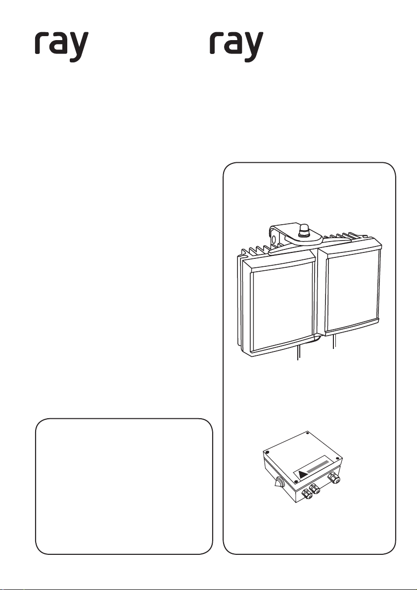
Overview
Package Contents
1. Illuminator
2. Power Supply (PSU)
GOLDEN RULES:
1. Ensure PSU lid orientation has
warning label in line with glands
(see PSU diagram, right)
2. Ensure operating voltage is
correct for unit being installed
3. DO NOT INPUT MAINS VOLTAGE
INTO LOW VOLTAGE PSU
4. Ensure PSU is fully water tight
Version 6.0
RAYMAX / RAYLUX illuminator
WARNING
!
PSU
Page 2
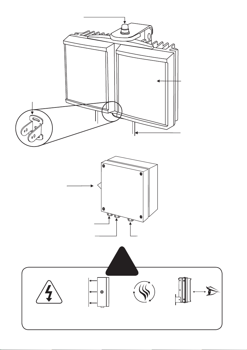
Adaptive illumination bolt
Bracket
Photocell
(automatic operation)
LED illuminator
LED output cable x2
2.5m (8.2ft)
LED output 1
LED output 2 Mains input
Isolate mains before
removing cover
Specifications subject to change without notice. Installation to be carried out by suitable trained and qualified personnel.
2
Mount PSU to
flat surface
!
Install in a well
ventilated area
Do not continually
stare at lamp
1.5 m
Page 3
Installation
1m - 9m
(3.3ft - 29.5ft)
Model dependent
Contact Raytec
2
Mains Lead
3
!
CAUTION: Red = +ve
Black = -ve
(polarity sensitive)
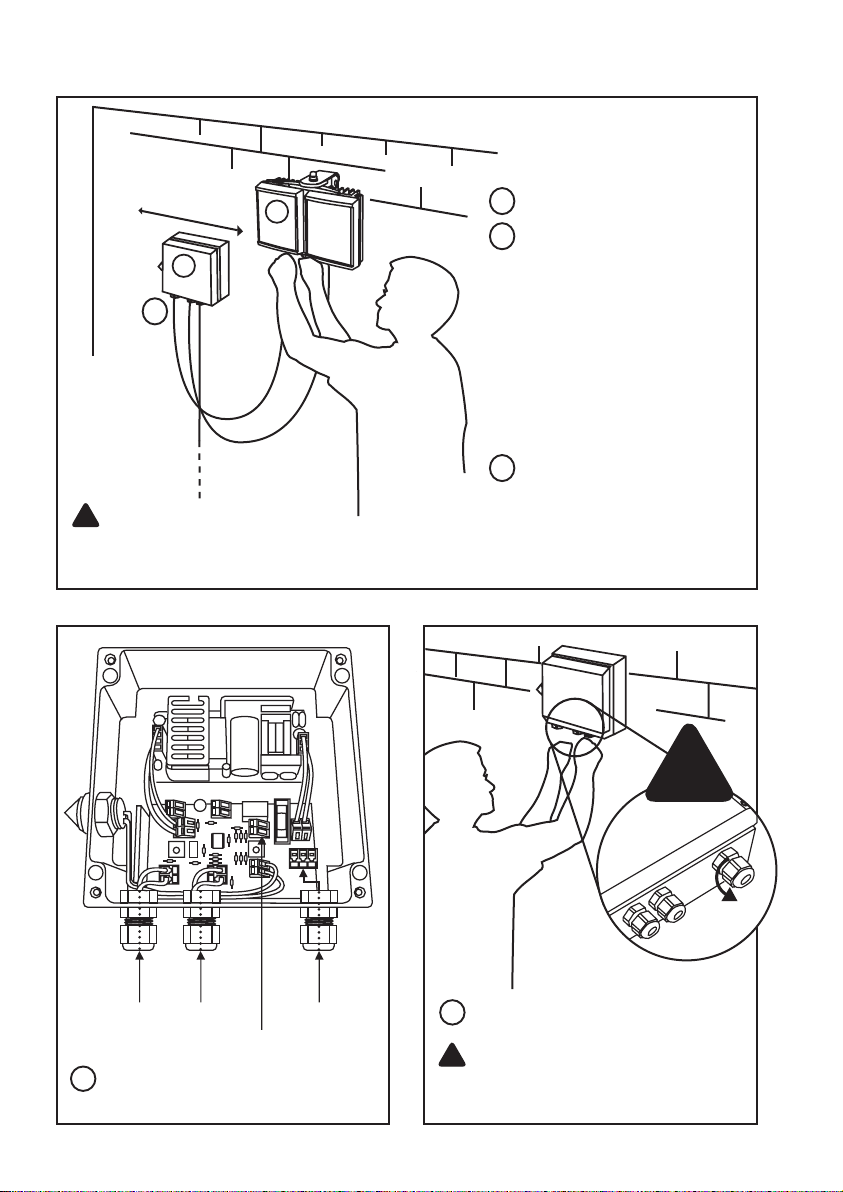
Mount illuminator
1
1
2
Mount PSU:
Do not position PSU
photocell facing illuminator
or other direct light sources
Photocell monitors ambient
lighting conditions
Mount PSU on wall/flat
surface with glands
facing down
Connect Illuminator to PSU:
3
Installers can extend or
reduce lead length using
appropriate cable and
weather proof box
LED Output x2
Telemetry Input
4
PSU connections.
Connect telemetry (if required)
Mains In
!
5
Connect PSU to Mains
!
CAUTION: Ensure cable glands
and PSU lid are water tight by
tightening the fixings
3
Page 4
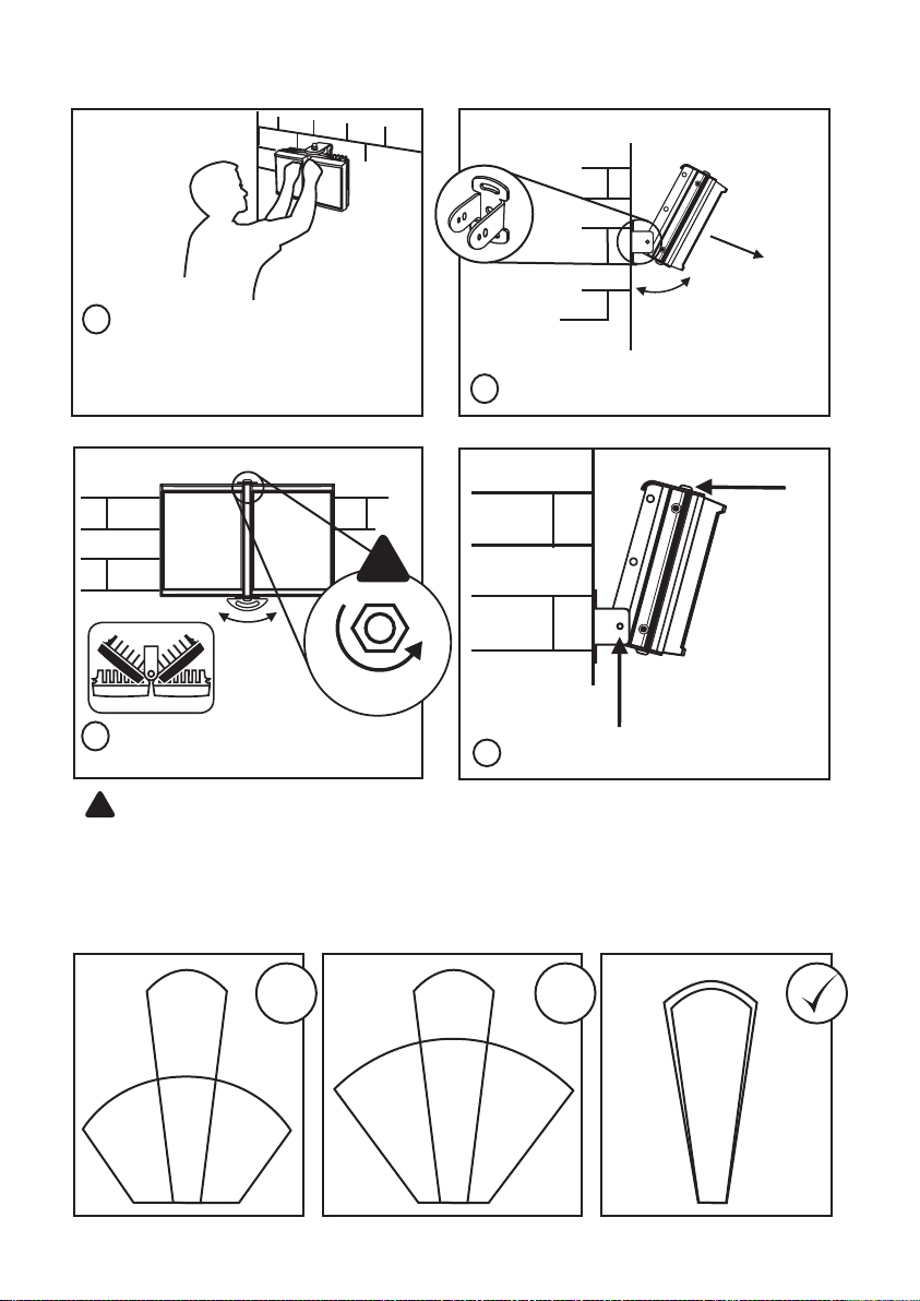
Set Up
1
Position illuminator adjacent to
camera and point towards scene
(Optional night set-up for
optimum image performance)
!
Max x2
2
Adjust vertical angle
TARGET
3
Adjust horizontal angle via Adaptive
Illumination (AI) (if required)
!
CAUTION: Do not fully loosen AI bolt.
Note: Power adjust available if required (see PSU diagrams, pages 8-9)
Tighten all fixings
4
Match illumination to camera field of view
Camera
Reduces performance May cause hot spots Best performance
4
x x
Light
Light
Camera
Camera
Light
Page 5

Technical Drawings (Not to scale)
Standard Bracketry
8.5mm
(0.3”)
48mm
(1.9”)
23.5mm
(0.9”)
47mm
(1.9”)
RM/RL 25
25mm
(1”)
100mm
(4”)
115mm
(4.5”)
8.5mm
(0.3”)
36mm
(1.4”)
52mm
(2”)
RM/RL 200/150/100/50
Optional Bracketry
Wall Mount Dome MountPtz Mount
72mm
(2.8”)
33mm
(1.2”)
RM/RL 300
140mm
(5.5”)
8.5mm
(0.3”)
Pole Mount
5
Page 6

PSU Specifications
INFRA-RED Series PSU
RM300 RM200 RM150 RM100 RM50 RM25
Input
Fuse 2.5A anti-surge 2.5A anti-surge 2.5A anti-surge 2.5A anti-surge 1A anti-surge 1A anti-surge
Typical Output
(Standard)
Typical Output
(IR PLATINUM)
Typical
Output
(IR Covert)
Adjustable
Power
Weight
Dimensions
L x W x D
Drilling
Dimensions
AC 100-230
universal<120W
6.6A @ 13.5V 4.4A @ 13.5V 3.6A @ 13.5V 2.4A @ 13.5V 1A @ 13.5V 0.5A @ 13.5V
9A @ 14V 6A @ 14V 6A @ 14V 4A @ 14V 2A @ 14V 1A @ 14V
9A @ 14V 6A @ 14V 6A @ 14V 4A @ 14V 2A @ 14V 1A @ 14V
10% - 100% 10% - 100% 10% - 100% 10% - 100% 10% - 100% 10% - 100%
2.3 kg
(5.1lbs)
240 x 160 x 81mm
(9.4 x 6.3 x 3.2”)
4 x M4 holes
@ 225 x 123mm
(8.9” x 4.8”)
AC 100-230
universal<80W
1.85 kg
(4.1lbs)
160 x 160 x 81mm
(6.3 x 6.3 x 3.2”)
4 x M4 holes
@ 145 x 123mm
(5.7” x 4.8”)
AC 100-230
universal<60W
2.3 kg
(5.1lbs)
240 x 160 x 81mm
(9.4 x 6.3 x 3.2”)
4 x M4 holes
@ 225 x 123mm
(8.9” x 4.8”)
AC 100-230
universal<40W
1.65 kg
(3.6lbs)
160 x 160 x 81mm
(6.3 x 6.3 x 3.2”)
4 x M4 holes
@ 145 x 123mm
(5.7” x 4.8”)
AC 100-230
universal<20W
0.9 kg
(2lbs)
130 x 130 x 60mm
(5.1 x 5.1 x 2.4”)
4 x M4 holes
@ 113 x 113mm
(4.4” x 4.4”)
AC 100-230
universal<10W
0.8 kg
(1.8lbs)
130 x 130 x 60mm
(5.1 x 5.1 x 2.4”)
4 x M4 holes
@ 113 x 113mm
(4.4” x 4.4”)
WHITE-LIGHT Series PSU
RL300 RL200 RL150 RL100 RL50 RL25
Input
Fuse 2.5A anti-surge 2.5A anti-surge 2.5A anti-surge 2.5A anti-surge 1A anti-surge 1A anti-surge
Typical Output 6.3A @ 13.5V 4.2A @ 13.5V 4.2A @ 13.5V 2.8A @ 13.5V 1.4A @ 13.5V 0.7A @ 13.5V
Adjustable
Power
Weight
Dimensions
L x W x D
Drilling
Dimensions
AC 100-230
universal<120W
10% - 100% 10% - 100% 10% - 100% 10% - 100% 10% - 100% 10% - 100%
2.3 kg
(5.1lbs)
240 x 160 x 81mm
(9.4 x 6.3 x 3.2”)
4 x M4 holes
@ 225 x 123mm
(8.9” x 4.8”)
AC 100-230
universal < 80W
1.85 kg
(4.1lbs)
160 x 160 x 81mm
(6.3 x 6.3 x 3.2”)
4 x M4 holes
@ 145 x 123mm
(5.7” x 4.8”)
AC 100-230
universal<60W
2.3 kg
(5.1lbs)
240 x 160 x 81mm
(9.4 x 6.3 x 3.2”)
4 x M4 holes
@ 225 x 123mm
(8.9” x 4.8”)
AC 100-230
universal <40W
1.65 kg
(3.6lbs)
160 x 160 x 81mm
(6.3 x 6.3 x 3.2”)
4 x M4 holes
@ 145 x 123mm
(5.7” x 4.8”)
AC 100-230
universal <20W
0.9 kg
(2lbs)
130 x 130 x 60mm
(5.1 x 5.1 x 2.4”)
4 x M4 holes
@ 113 x 113mm
(4.4” x 4.4”)
AC 100-230
universal <10W
0.8 kg
(1.8lbs)
130 x 130 x 60mm
(5.1 x 5.1 x 2.4”)
4 x M4 holes
@ 113 x 113mm
(4.4” x 4.4”)
HYBRID Series PSU
Input Fuse Typical Output
6
AC 100-230
universal<120W
2.5A anti-surge
Model
dependent
Contact Raytec
Adjustable
Power
10% - 100%
Weight
2.3 kg
(5.1lbs)
Dimensions
L x W x D
240 x 160 x 81mm
(9.4 x 6.3 x 3.2”)
Drilling
Dimensions
4 x M4 holes
@ 225 x 123mm
(8.9” x 4.8”)
Page 7

Low Voltage PSU (LVP) Specification
INFRA-RED AND WHITE-LIGHT Series PSU
(Excluding Platinum and Covert Series)
300 200 150 100 50 25
Input x 24V AC/DC x 24V AC/DC 12/24V AC/DC 12/24V AC/DC
Fuse x 5A x 5A 3A 3A
Typical Output
(Infra-Red)
Typical Output
(White-Light)
Adjustable
Power
Weight x
Dimensions
L x W x D
Drilling
Dimensions
!
NOTE: Ensure operating voltage is correct for unit being installed.
DO NOT INPUT MAINS VOLTAGE INTO LOW VOLTAGE PSUs.
x 4.4A @ 13.5V x 2.4A @ 13.5V 1A @ 13.5V 0.5A @ 13.5V
x 4.2A @ 13.5V x 2.8A @ 13.5V 1.4A @ 13.5V 0.7A @ 13.5V
x 10% - 100% x 10% - 100% 10% - 100% 10% - 100%
x
x
1.85 kg
(4.1lbs)
160 x 160 x 81mm
(6.3 x 6.3 x 3.2”)
4 x M4 holes
@ 145 x 123mm
(5.7” x 4.8”)
x
x
x
1.65 kg
(3.6lbs)
160 x 160 x 81mm
(6.3 x 6.3 x 3.2”)
4 x M4 holes
@ 145 x 123mm
(5.7” x 4.8”)
0.9 kg
(2lbs)
130 x 130 x 60mm
(5.1 x 5.1 x 2.4”)
4 x M4 holes
@ 113 x 113mm
(4.4” x 4.4”)
130 x 130 x 60mm
(5.1 x 5.1 x 2.4”)
@ 113 x 113mm
0.8 kg
(1.8lbs)
4 x M4 holes
(4.4” x 4.4”)
Power Supply Features
STANDARD PSU
• Adjustable photocell
• Adjustable power
• Telemetry input
PREMIUM PSU-PR
• Adjustable photocell
• Adjustable power
• Telemetry input
• Photocell following
contact, volt free relay
contact - normally open
(day) to normally closed
(night)
• 12V DC output @ 1.5A
PULSED PSU - PU
• Analogue version
• TTL version
• No photocell
• Adjustable power
• 12V DC output @ 1.5A
• Synchronised with
camera
PREMIUM TIMER PSU-PRT
• Adjustable photocell
• Adjustable power
• Telemetry input
• Photocell following
contact, volt free relay
contact - normally open
(day) to normally closed
(night)
• 12V DC output @ 1.5A
• Timer function
Maximum Projected Area (M²)
RM/RL25 (Single panel) 0.0086
(Single panel) 0.0155
RM/RL50
RM/RL50 Adaptive Illumination™
(Double panel)
RM/RL100 (Single Panel) 0.0279
RM/RL100 Adaptive
Illumination™
RM/RL150 Adaptive
Illumination™
RM/RL200 Adaptive
Illumination™
RM/RL300 Adaptive
Illumination™
(Double Panel)
(Triple Panel)
(Double Panel)
(Triple Panel)
0.0173
0.0311
0.0466
0.0559
0.0838
7
Page 8
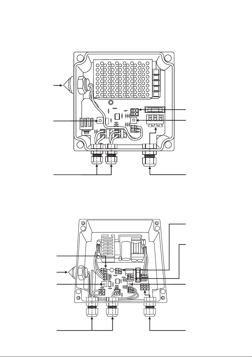
Power Supply Diagrams (Not to scale)
INFRA-RED and WHITE-LIGHT
RM/RL 50/25 Models
(Not to scale)
Photocell
Power Adjust
Telemetry Input
- requires zero volt,
latched input
Photocell Sensitivity
LED Output x2
(Polarity Sensitive)
INFRA-RED and WHITE-LIGHT
RM/RL 200/100 Models
(Not to scale)
12V DC power
(Premium PSU only)
(Polarity Sensitive)
output
Photocell
Power Adjust
LED Output x2
(Model shown: RM/RL 100 Premium)
Mains Input
100V to 230V AC
Auto-Sensing
Photocell following
contact - volt free,
non polarity sensitive
(Premium PSU only)
Telemetry Input
- requires zero volt,
latched input
Photocell Sensitivity
Mains Input
100V to 230V AC
Auto-Sensing
8
Page 9

INFRA-RED and WHITE-LIGHT
RM/RL 300/150 and Hybrid Models
(Final specification model dependant - model shown: RM/RL 300 Premium)
Note - Hybrid control boards will be labelled IR/WL
Photocell
Photocell
Sensitivity
Photocell
12V DC Power
Output (Premium
PSU only)
Power Adjust
following contact
- volt free, non
polarity sensitive
(Premium PSU only)
Telemetry Input
requires zero volt,
latched input
Up to x3
LED Output
(Polarity Sensitive)
(Model Dependant)
Mains Input
(100V to 230V AC)
Auto-Sensing
Hybrid PSU Models
Factory Setting:
IR controlled by photocell
WL controlled by telemetry night time only
Attach 1 wire of volt free input into photocell following output on top control board and other
wire of volt free input into telemetry input on bottom board.
Other set up options available...contact Raytec.
9
Page 10

Trouble Shooting
Ensure all tests are undertaken by a qualified, trained engineer
Ensure safe working practices are followed at all times
PLEASE NOTE: If the external flexible cable or cord is damaged, it shall be
exclusively replaced by manufacturer, service agent or similarly qualified person
to avoid a hazard.
Step 1: Basics
• Check polarity of Lamp connection
red=+ve, black=-ve
• Check telemetry link is in
• Check photocell is working
• Check power setting pot fully clockwise
• Check mains input
• Check fuse intact
If OK…
Step 2: Lamp Test
Check voltage of lamp o/p approx 14V (8V for pulsed units)
Check current of lamp – see instructions for correct current setting
To check lamp current (this must be done while both LED panels are connected to
the PSU) remove +ve LED from both lamp supply cables and connect multimeter
set to 10A current in line with the lamp. [One lead of multimeter in common (COM),
other lead into 10A socket of multimeter; set multimeter to 10A readings]. Refer to
PSU Specifications for correct current settings, see pages 6-7.
Step 3: Set-up Camera, lens and illumination
Check alignment of lamp
Check camera lens – fully open at night & set correctly
Check model number to Raytec performance specification to ensure required
distance is achievable
10
Page 11

Step 4: Call Raytec for further assistance
Note down:
• Model and serial number of illuminator
• Camera make and model
• Lens make and model
If the Raytec lamp is still not delivering the required performance, please contact
us for further assistance.
Additional Information
UL 1838 & CSA 22.2 No 9.0 – 96 Classification
• Suitable for indoor and outdoor use
• Suitable for use in wet locations
• Suitable for mounting on flammable surfaces
• Suitable for combustible surface use
• Suitable for temperatures not exceeding 35°C
Do not connect PSU to an ungrounded supply
Do not install within 10ft of pool or spa
Do not use with dimmers
Do not connect two or more power supplies in parallel
This product must be installed by a person familiar with the construction and operation of
the product and the hazards involved, in accordance with the applicable installation code.
The device is accepted as a component of a landscape lighting system where the
suitability of the combination shall be determined by CSA or local inspection authorities
having jurisdiction. Such systems should be protected by a ground fault circuit interrupter
of the Class A type.
Raytec Warranty
Please register you Raytec LED Illuminator(s) for its 5 year warranty by visiting
www.rayteccctv.com/products/warranty-card
11
Page 12

RRII/13/2.1
12
UK / Europe
T: +44 (0) 1670 520055
F: +44 (0) 1670 819760
sales@rayteccctv.com
Americas (Toll Free)
T: +1 888 505 8335
ussales@rayteccctv.com
www.rayteccctv.com
 Loading...