

Page 1

CATALOG NO. 2100.52A Effective: 05-22-13 Replaces: 06-01-09
Page 2

Subject to technical changes!
Slight changes may be made to the illustrations, process steps
and technical data as a result of our policy of continuous
improvement.
About these instructions
These Installation Instructions contain important information for
the safe and professional installation, start-up and maintenance
of the boiler with boiler capacities 87,000 and 120,000 btu/hr.
These Installation Instructions are intended for qualified installers,
who have the necessary training and experience for working on
heating and gas systems.
About the XPak
The boiler was designed for heating water for a space heating
system and generating hot water e.g. for domestic purposes.
The boiler can be fitted with a remote control or an On/Off room
thermostat (24 V), external sensor and with a 3-way valve for
DHW indirect storage tank controlled either with a tank thermostat
or a tank sensor (accessories).
Dear Costumer,
Thank you for choosing the XPak
boiler. This Raypak product provides
more efficiency and greater comfort to
the living space, thanks to its unique
features.
The new patented aluminum heat
exchanger provides ultra low
emissions, higher efficiency and easier
recycling after the boiler life.
Rev. A reflects the following:
Changes to: ASME Mark on page 1, AFUE values on page 10, piping diagrams on pages 19-21, Flue Gas
System on page 25, Warranty on pages 65-66.
Additions: Fig. 32A on page 33.
2
Page 3

CONTENTS
1 - WARNINGS 4
PAY ATTENTION TO THESE TERMS 4
2 - GENERAL SAFETY 6
TIME/TEMPERATURE RELATIONSHIPS IN SCALDS 6
3 - BEFORE INSTALLATION 6
4 - REGULATIONS AND GUIDELINES 7
5 - INTRODUCTION 8
TECHNICAL DATA 10
PRINCIPLE COMPONENTS 12
MODE OF OPERATION (AT REST) 12
MODE OF OPERATION 12
SAFETY DEVICES 12
BANNED MATERIAL STATEMENT 12
MANUAL HANDLING STATEMENT 12
XPAK INTERNAL HYDRAULIC CIRCUIT 12
PIPING CONNECTIONS 13
DIMENSIONS AND CONNECTIONS 1 4
PACKAGING AND TRANSPORTATION 15
1. Scope of delivery 15
2. Transporting the boiler 15
3. Boiler box content 15
6 - INSTALLATION 16
PREPARE XPAK LOCATION 16
1. Installations must comply with 16
2. Before locating the XPak boiler 16
3. Clearances for service access 16
4. Residential garage installation 16
5. Exhaust vent and intake air vent 16
6. Prevent combustion air contamination 16
7. When removing an existing boiler from an existing common 16
vent system
PREPARE XPAK 16
1. Remove XPak boiler from box 16
2. Placing the wall-mounted XPak boiler 17
3. XPak wall mounting instructions 17
4. Installation steps 17
XPAK PIPING 17
1. Relief valve 17
2. General piping information 17
3. Separate low water cutoff 17
4. Backflow preventer 17
5. Fitting the heating circuit supply and return pipes 17
6. Expansion tank and make-up water 17
7. Sizing space heat system piping 17
8. Boiler with DHW tank 18
9. Waterside Flow (primary circuit) 18
10.Procedure summary 18
11.Fill and purge heating system 18
XPAK INSTALLATION DIAGRAMS 19
MAKING THE GAS CONNECTION 22
BOILER TEMPLATE 23
COMBUSTION AIR AND VENTILATION OPENINGS 24
INSTALLATION OF THE EXHAUST AND AIR INTAKE SYSTEM 24
VENT SYSTEMS 25
1. Flue gas system 25
2. Boiler supply 25
3. Installations of supplied vent components 25
4. Minimum Clearances from Vent/Air Inlet Termination 26
CONNECTING THE CONDENSATE WATER DRAIN 34
1. Condensate Connection 34
7 - ELECTRICAL CONNECTIONS 34
1. External connection board connections 34
2. Electrical supply 34
3. Field wiring 34
4. Casing removal 35
5. Appliance terminal block 35
6. Connecting the electrical supply (120V) 35
7. External wiring 35
8. External wiring limitations 35
9. Connecting thermostat 35
10.Other devices 35
11 .Terminal strip details 36
12.Outdoor sensor connection 3 7
13.3-way valve wiring connection 3 7
14.Remote control connection 37
WIRING FUNCTIONAL DIAGRAM 38
9 - COMMISSIONING 40
1. Check/control water chemistry 40
2. Freeze protection (when used) 40
3. The heating system 40
4. Initial filling of the system 40
5. Purge air from boiler manual air release 40
6. System drain 40
7. Check thermostat circuit(s) 41
8. Testing for gas leaks 41
9. Initial flushing of the system 41
10. Pre-operation checks 4 1
11. Initial lighting 41
12. Checking gas pressure and combustion analysis 41
13. Final flushing of the heating system 41
14. Setting the boiler operating temperature 41
15. Regulating the central heating system 41
16.Final checks 42
17.Instructing the user 42
18.Warranty 42
10 - START-UP AND OPERATION 43
1. Switching on the appliance 43
2. How to read the display temperature 43
3. Adjusting heating water temperature with an outdoor probe connected 43
4. Adjusting domestic hot water temperature (if a storage tank with
sensor and 3-way valve is installed) 43
5. Working the boiler 43
6. Reset function 43
7. Switching off 43
8. Indicator LEDs and faults 44
11 - CHECKS, ADJUSTMENTS AND FAULT FINDING 46
1. Checking appliance operation 46
2. Appliance modes of operation 46
3. Selector switch in the off/stand by position 46
4. On-board functions 46
5. Heating mode 46
6. DHW mode 46
7. Boiler fan speeds 47
8. Checking the CO2 and adjusting the gas valve 47
9. Gas valve maximum setting 47
10 .Gas valve minimum setting 47
11.Combustion analysis test 47
12. External faults 47
13. Electrical checks 48
14.Component values & characteristics 48
15 .Boiler configuration 48
16.Setting the outdoor reset curve with outdoor sensor 49
17 .Fault codes 51
12 - SERVICING INSTRUCTIONS 52
1. General 52
2. Routine annual servicing 52
3. Replacement of components 52
4. Component removal procedure 52
13 - LPG INSTRUCTIONS 56
PROPANE GAS 56
14 - EXPLODED DIAGRAMS 59
IMPORTANT INSTRUCTIONS FOR THE
COMMONWEALTH OF MASSACHUSETTS 64
LIMITED PARTS WARRANTY 65
START-UP CHECKLIST FOR FAN-ASSISTED
RAYPAK PRODUCTS 67
8 - START-UP PROCEDURE 39
3
Page 4
1 - WARNINGS -
PAY ATTENTION TO THESE TERMS
DANGER:
Indicates the presence of immediate hazards which will cause severe personal injury, death or substantial property
damage if ignored.
WARNING:
Indicates the presence of hazards or unsafe practices which
could cause severe personal injury, death or substantial
property damage if ignored.
CAUTION:
Indicates the presence of hazards or unsafe practices which
could cause minor personal injury or product or property
damage if ignored.
NOTICE:
Indicates special instructions on installation, operation, or
maintenance which are important but not related to personal
injury hazards.
DANGER: Make sure the gas on which the boiler will operate
is the same type as that specified on the boiler rating plate and
on the coloured sticker near the boiler gas connection.
WARNING: Should overheating occur or the gas supply valve
fail to shut, do not turn off or disconnect the electrical supply to
the boiler. Instead, shut off the gas supply at a location e xternal
to the boiler.
WARNING: Do not use this boiler if any part has been under
water. Immediately call a qualified service technician to inspect
the boiler and to replace any part of the control system and any
gas control which has been under water.
AVERTISSEMENT: En cas de surchauffe ou de non fermeture
de la vanne d’alimentation en gaz, n’éteignez ou ne
débranchez pas l’alimentation électrique de la chaudière.
Coupez plutôt l’alimentation en gaz à l’extérieur de la
chaudière.
AVERTISSEMENT: N’utilisez pas cette chaudière si une partie
de celle-ci s’est retrouvée sous l’eau. Appelez immédiatement
un technicien de service qualifié pour inspecter la chaudière
et pour remplacer toute partie du système de contrôle et toute
commande de gaz s’étant retrouvée sous l’eau.
WARNING: To minimize the possibility of improper operation,
serious personal injury, fire, or damage to the boiler:
• Always keep the area around the boiler free of combustible
materials, gasoline, and other flammable liquids and vapors.
• Boiler should never be covered or have any blockage to the
flow of fresh air to the boiler.
WARNING: Risk of electrical shock. More than one disconnect
switch may be required to de-energize the equipment before
servicing.
WARNING - CALIFORNIA PROPOSITION
65: This product contains chemicals known to the State of
California to cause cancer, birth defects or other reproductive
harm.
CAUTION: This boiler requires forced water circulation when
the burner is operating. See minimum and maximum flow rates.
Severe damage will occur if the boiler is operated without proper
water flow circulation.
NOTE: Minimum 18 AWG, 105°C, stranded wire must be used
for all low voltage (less than 30 volts) external connections to
the unit. Solid conductors should not be used because they
can cause excessive tension on contact points. Install conduit
as appropriate. All high voltage wires must be the same size
(105°C, stranded wire) as the ones on the unit or larger.
NOTE: When the boiler has been filled for the first time or the
system has been drained and refilled, it will be necessary to
release any air that may have become trapped within the
appliance heat exchanger. Loosen the bleed screw until water
is released and then close.
IMPORTANT, THERE ARE NO OTHER MANUAL AIR
RELEASE VALVES LOCATED ON THE APPLIANCE.
The following instructions must be observed
– The boiler must only be used for its designated purpose,
observing the Installation Instructions.
– Only use the boiler in the combinations and with the
accessories and spares listed.
– Other combinations, accessories and consumables must only
be used if they are specifically designed for the intended
application and do not affect the system performance and the
safety requirements.
– Maintenance and repairs must only be carried out by
authorized professionals.
– You must report the installation of a condensing gas boiler to
the relevant gas utility company and have it approved.
– You are only allowed to operate the condensing gas boiler
with the combustion air/flue gas system that has been
specifically designed and approved for this type of boiler.
– Please note that local permission for the flue system and the
condensate water connection to the public sewer system may
be required.
You must also observe:
– The local building regulations stipulating the installation rules.
– The local building regulations concerning the air intake and
outlet systems and the chimney connection.
– T he regulations for the power supply connection.
– The technical rules laid down by the gas utility company
concerning the connection of the gas burner fitting to the local
gas main.
– The instructions and standards concerning the safety
equipment for the water/space heating system.
– The Installation Instructions for building heating systems.
– The boiler must be located in an area where leakage of the
tank or connections will not result in damage to the area
adjacent to the boiler or to lower floors of the structure. When
such locations cannot be avoided, it is recommended that a
suitable drain pan, adequately drained, be installed under
the boiler. The pan must not restrict combustion air flow.
– The boiler must be installed such that the gas ignition system
components are protected from water (dripping, spraying, rain
etc.) during boiler operation and service.
– The boiler must not be installed on carpeting.
– The boiler must only be installed on a wall.
– Do not restrict or seal any air intake or outlet openings.
– If you find any defects, you must inform the owner of the system
of the defect and the associated hazard in writing.
4
Page 5

DANGER
if flammable gas explodes.
Beware if you smell gas: there may be an explosion hazard!
Warning: If the information in these instructions is not followed
exactly, a fire or explosion may result causing property
damage, personal injury or death.
- Do not store or use gasoline or other flammable vapors and
liquids in the vicinity of this or any other boiler.
What to do if you smell gas
- Do not try to light any boiler.
- Do not touch any electrical switch; do not use any phone in your
building.
- Immediately call your gas supplier from a neighbor’s phone.
Follow the gas supplier’s instructions.
- If you cannot reach your gas supplier, call the fire department.
Installation and service must be performed by a qualified installer,
service agency or the gas supplier.
Observe these instructions as general warnings:
– Chemicals used to clean the system and/or inhibit corrosion
must be pH neutral, i.e. they should ensure that the level of the
pH in the system water remains neutral.
Premature failure of certain components can occur if the pH
level in the system water is out of normal levels.
– Raypak recommends that an inhibitor - suitable for use with
aluminum heat exchangers - is used to protect the boiler and
system from the effects of corrosion and/or electrolytic action.
The inhibitor must be administered in strict accordance with
the manufacturers instructions.
– A properly sized expansion tank must be installed in the boiler
system. No valve is to be placed between the boiler and the
expansion tank.
– When the boiler has been filled for the first time or the system
has been drained and refilled, it will be necessary to purge
any air that may have become trapped within the appliance
heat exchanger.
NOTE: Glycol in the system must not exced 40%.
Observe these instructions for space heating water:
– Thoroughly flush the system prior to filling.
Only use untreated main water to fill and top off the system.
– Do not use water softners in the system.
– Do not use inhibitors or other additives!
– The maximum permissible flow rate of the XPAK 85 this is 5.7
GPM (1,300 ltr/hr), for the XPAK 120 is 6.2 GPM (1,400 ltr/hr).
– When using oxygen-permeable pipes, e.g. for floor heating
systems, you must separate the system using heat exchangers.
Unsuitable heating system water promotes the formation of
sludge and corrosion. This may damage the heat exchanger
or affect its operation.
– A properly sized expansion tank must be installed in the boiler
system.
T ools, materials and additional equipment
For the installation and maintenance of the boiler you will need
the standard tools for space heating, gas and water fitting.
In addition, a handtruck with a fastening belt is very useful.
Disposal
– Dispose of the boiler packaging in an environmentally sound
manner.
– Dispose of components of the heating system (e. g. boiler or
control device), that must be replaced, by handing them in to
an authorized recycling facility.
5
Page 6
2 - GENERAL SAFETY
T o meet domestic hot water use needs , the high limit safety control
on this boiler is adjustable up to 140°F (60°C).Water temperatures
over 125°F (50°C) can cause instant severe burns or death from
scalds.
When supplying general purpose hot water, the recommended
initial setting for the temperature control is 125°F (50°C).
Safety and energy conservation are factors to be considered
when setting the water temperature on the thermostat. The most
energy-efficient operation will result when the temperature setting
is the lowest that satisfies the needs of the application.
Water temperature over 125°F (50°C) can cause instant severe
burns or death from scalds. Children, disabled and elderly are at
highest risk of being scalded.
• Feel water before bathing or showering.
• Temperature limiting valves are available.
NOTE: When this boiler is supplying general purpose hot
water for use by individuals, a thermostatically controlled
mixing valve for reducing point of use water temperature is
recommended to reduce the risk of scald injury. Contact a
licensed plumber or the local plumbing authority for further
information.
Maximum water temperatures occur just after the boiler’s burner
has shut off. To determine the water temperature being deliv ered,
turn on a hot water faucet and place a thermometer in the hot
water stream and read the thermometer.
WARNING: This boiler cannot supply hot water for use by
individuals directly. A heat exchanger must be used in
conjunction with this boiler to meet DHW needs.
TIME/TEMPERATURE
RELATIONSHIPS IN SCALDS
The following chart details the relationship of water temperature
and time with regard to scald injury and may be used as a guide
in determining the safest water temperature for your applications.
Water Time to Produce Serious
Temperature Burn
120°F More than 5 minutes
125°F 1-1/2 to 2 minutes
130°F About 30 seconds
135°F About 10 seconds
140°F Less than 5 seconds
145°F Less than 3 seconds
150°F About 1-1/2 seconds
155°F About 1 second
Table courtesy of The Shriners Burn Institute
The temperature of the water in the boiler can be regulated by
using the Raypak Remote Control REC08. To comply with safety
regulations, the control is set when shipped from the factory.
CAUTION: Hotter water increases the risk of scalding! There
is a hot water scald potential if the thermostat is set too high.
3 - BEFORE INSTALLATION
Raypak strongly recommends that this manual be reviewed
thoroughly before installing your XPak boiler. Please review the
General Safety information before installing the boiler. Factory
warranty does not apply to boilers that have been improperly
installed or operated. (Refer to the warranty at the back of this
manual.) Installation and service must be performed by a qualified
installer, service agency or gas supplier. If, after reviewing this
manual, you still have questions which this manual does not
answer, please contact the manufacturer or your local Raypak
representative. Thank you for purchasing a Raypak product. We
hope you will be satisfied with the high quality and durability of
our equipment.
Product Receipt
On receipt of your boiler it is suggested that you visually check
for external damage to the shipping package. If the package is
damaged, make a note to that effect on the Bill of Lading when
signing for the shipment. Remove the boiler from the shipping
packaging. Report any damage to the carrier immediately. On
occasion, items are shipped loose. Be sure that you receive the
correct number of packages as indicated on the Bill of Lading.
Claims for shortages and damages must be filed with the carrier
by consignee. Permission to return goods must be received from
Raypak prior to shipping. Goods returned to the factory without
an authorized Returned Goods Receipt number will not be
accepted. All returned goods are subject to a restocking charge.
When ordering parts, you must specify the model and serial
number of the boiler. When ordering under warranty conditions,
you must also specify the date of installation. Purchased parts
are subject to replacement only under the manufacturer’s
warranty. Debits for defective replacement parts will not be
accepted and will be replaced in kind only per Raypak’ s standard
warranty.
Model Identification
The model identification number and boiler serial number are
found on the boiler rating plate located on the casing right side.
Also the boiler serial number can be found on the back page of this
manual and inside the front control panel flap.
6
Page 7

Ratings and Certifications
Standards:
• Gas fired hot water boiler for either direct vent installation or for
installation using indoor combustion air. Design according to:
ANSI Z21.13b 2007 – CSA 4.9b 2007 – Fired low pressure hot
water boilers. Categor y IV.
• SCAQMD Rule 1146.2
All Raypak boilers are National Board Approved, and designcertified and tested by the Canadian Standards Association
(CSA) for the U.S. and Canada. Each boiler is constructed in
accordance with Section IV of the American Society of Mechanical
Engineers (ASME) Boiler Pressure Vessel Code and bears the
ASME H stamp. This boiler also complies with the latest edition
of the ASHRAE 90.1 Standard.
WARNING: Altering any Raypak pressure v essel by installing
replacement heat exchangers, tube bundle headers, or any
ASME parts not manufactured and/or approved by Raypak
will instantly void the ASME and CSA ratings of the vessel
and any Raypak warranty on the vessel. Altering the ASME
or CSA ratings of the vessel also violates national, state,
and local approval codes.
Installations at Elevation
Rated inputs are suitable for up to 4,500 ft elevation (see technical
data table). Consult the factory for installations at altitudes over
4,500 ft above sea level. No hardware changes are required to
the boilers for installations up to 10,000 ft (adjustments may be
required).
4 - REGULATIONS AND
GUIDELINES
The installation must be conform to the requirements of the
authority having jurisdiction or, in the absence of such
requirements, to the latest edition of the National Fuel Gas
Code, ANSI Z223.1. In Canada, installation must be in
accordance with the requirements of CAN/CSA B149.1,
Natural Gas and Propane Installation Code. Where required
by the authority having jurisdiction, the installation must
conform to the Standard for Controls and Safety Devices for
Automatically Fired Boilers, ANSI/ASME CSD-1.
Install CO detectors per local regulations. Boiler requires
yearly maintenance, see chapter “Checks, adjustments and
fault finding”.
Operating Limits of the boiler:
Max. boiler temperature: 194°F (90 °C)
Max. operating pressure: 45 psi (3.1 bar)
The hot water distribution system must comply with all
applicable codes and regulations. When replacing an e xisting
boiler, it is important to check the condition of the entire hot
water distribution system to ensure safe operation.
7
Page 8
5 - INTRODUCTION
The XPak boiler is a wall hung, fan assisted, direct vent, heating
boiler only. These boilers – by design – incorporate electronic
ignition, circulating pump, pressure relief valve, pressure gauge,
and automatic bypass.
As supplied, the boiler will automatically modulate to provide
central heating outputs between 25,600 - 87,000 Btu/hr (7.5-25.5
kW) - XPak 85 and 27,300 - 119,500 Btu/hr (8-35 kW) XPak 120.
IMPORTANT
It is the law that all gas appliances are installed by a competent
person.
It is in your own interest and that of safety to ensure that the law is
complied with.
• The installation must conform to the requirements of the authority
having jurisdiction or, in the absence of such requirements, to
the National Fuel Gas Code, ANSI Z223.1/NFPA 54 Where
required by the authority having jurisdiction, the installation must
conform to the Standard for Controls and Safety Devices for
Automatically Fired Boilers, ANSI/ASME CSD-1.
• The installation should conform with CGA B149 INST ALLATION
CODE and/or local installation Code, plumbing or waste water
codes and other codes as applicable.
• Clearances from combustible material must be strictly adhered to.
• Manufacturers instructions must NOT be interpreted in anyway
as overriding statutory obligations.
The XPak family comprises a range of high-efficiency hot water
boilers with outputs ranging from 87,000 Btu/hr (25.5 kW) to
119,500 Btu/hr (35 kW). Each appliance is provided with a fan
powered flue outlet with an annular co-axial combustion air intake
that can be rotated – horizontally – through 360 degrees for
various horizontal or vertical applications. The XPak can also be
used with two pipe flue vent system. These appliances are
designed for use with a sealed system only; consequently they
are not intended for use on open vented systems.
This booklet is an integral part of the appliance. It is therefore
necessary to ensure that the booklet is handed to the person
responsible for the property in which the appliance is located/
installed. A replacement copy can be obtained from Raypak
customer services.
R
XPAK 120
XPAK 85
GF
P
C
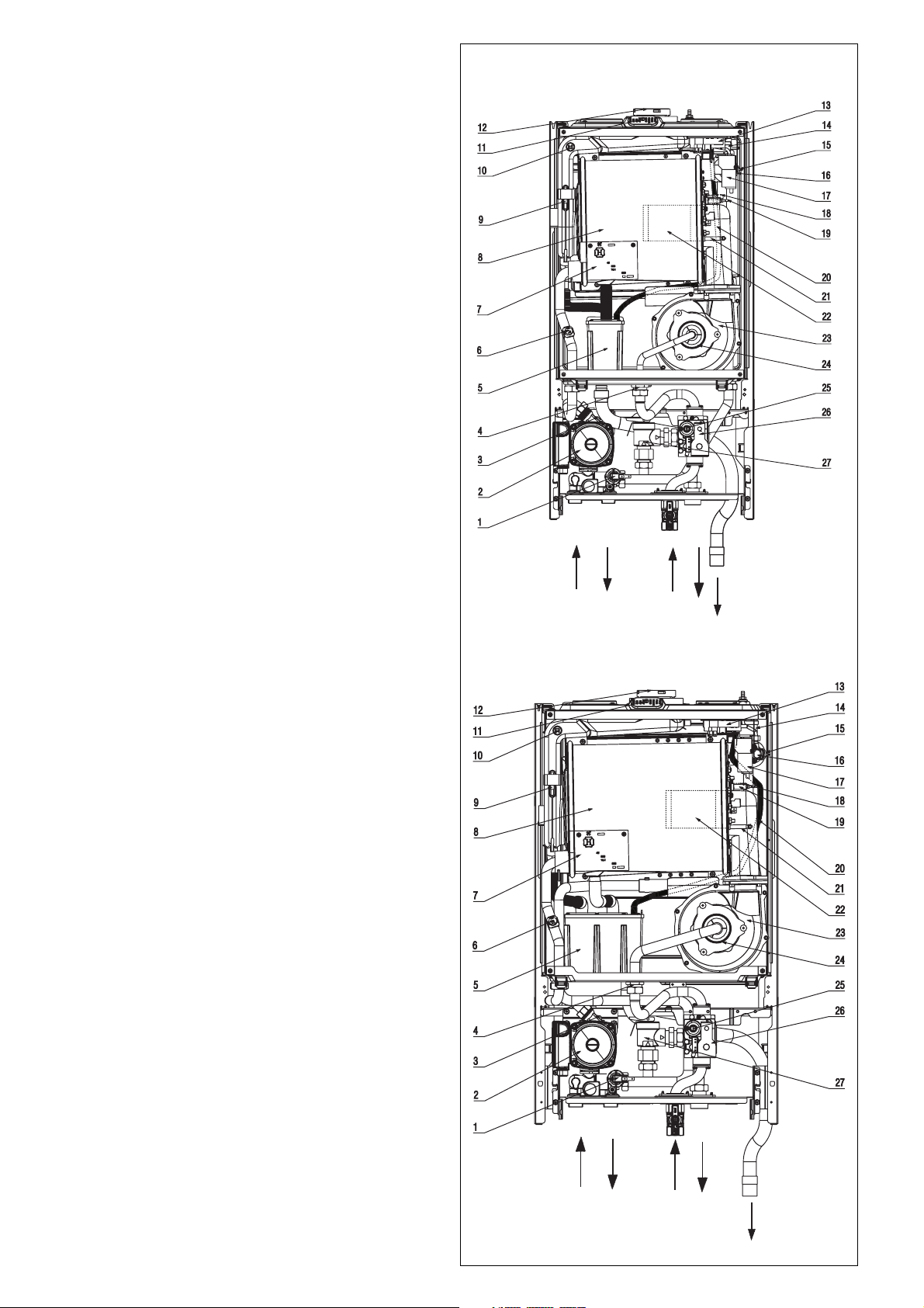
General layout (Fig. 1)
1 Water pressure switch
2 Pump
3 Bottom auto air vent (AAV)
4 Gas injector
5 Condense trap
6 Return sensor
7 H stamp main heat exchanger
8 Main heat exchanger
9 Flue thermostat
10 Flue sensor
11 Flue gas analysis test point
12 Flue outlet & air intake
13 Blocked flue switch
14 Top automatic air vent
15 Flow sensor
16 High limit thermostat
17 Ignition transformer
18 Sensing Electrode
19 Spark Electrode
20 Top automatic air vent drain pipe
21 Condensate level sensor
22 Cylindric Burner
23 Fan assembly
24 Mixer
25 Gas modulator coil
26 Gas valve
27 Pressure relief valve
R Boiler IN connection
F Boiler OUT connection
G Gas connection
P Pressure relief valve drain
C Condensate drain pipe
8
Fig. 1
R
F
G
P
C
Page 9
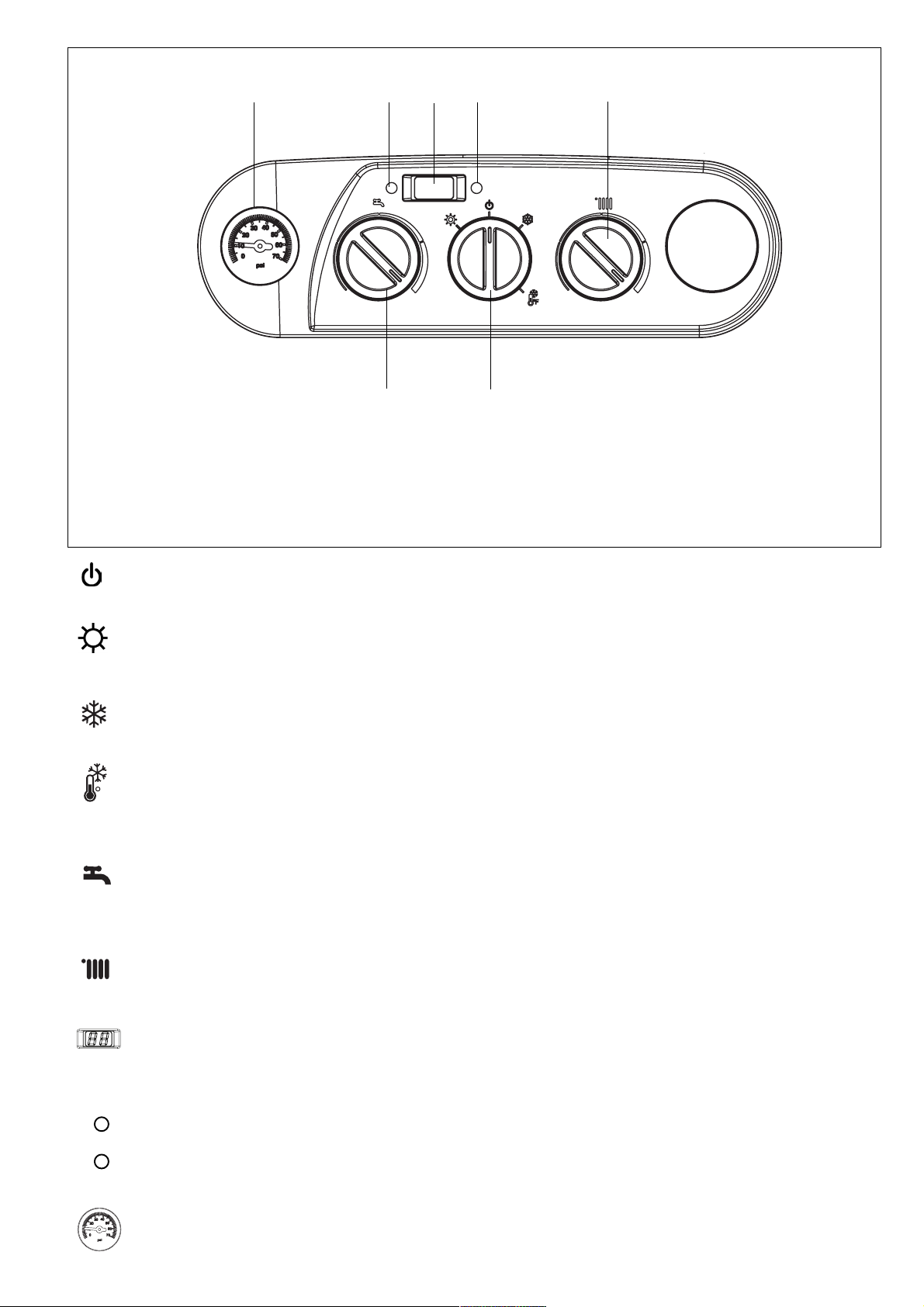
Fig. 1A
A
A Pressure gauge
B Green led
C 2-digit LED display
D Red led
E Temperature selector space heating
F Mode selector switch
G Temperature selector Domestic Hot Water
BC
G
D
E
F
Off/reset - Select this position when the boiler needs to be
reset or switched off.
Summer mode - The domestic hot water function provided
by the water tank is activated. The display indicates the
storage tank temperature (only with the external water tank
connected with a sensor).
Winter mode - The boiler produces hot water for heating
and, if connected to an external water tank, it provides
domestic hot water. The display indicates the boiler flow temperature.
Winter mode tank temperature - The boiler produces hot
water for heating and, if connected to an external water tank
F
with a sensor, it provides domestic hot water. The display
indicates the storage tank temperature.
Temperature selector DHW- Move the temperature selector
clockwise to increase the hot water temperature in the water
tank or counter-clockwise to reduce the temperature (working
only if a tank sensor is connected).
Temperature selector Heating - Move the temperature
selector clockwise to increase the heating temperature or
counterclockwise to reduce the temperature.
2-digit LED display - Displays the temperature according
the mode selector switch. During a fault condition, the
appropriate code will be displayed (refer to the installation
instructions regarding fault codes).
Green LED lit - Boiler is working/responding to a heating/
tank request (flame ON).
Red LED lit - Boiler has identified a fault and has shut down.
Refer to installation instructions on how to reset.
Pressure gauge - Ensure the system pressure is set
correctly (minimum 7 p.s.i. (0.45 bar))
9
Page 10
TECHNICAL DATA
Tab. 1
Input - Output
Input - (0 - 2000 ft / 0 - 610 m) Btu/hr 25,600 - 87,000 27,300 - 119,500
kW 7.5 - 25.5 8.0 - 35.0
Input - (2000 - 4500 ft / 610 - 1375 m) Btu/hr 25,600 - 82,900 27,300 - 114,300
kW 7.5 - 24.3 8.0 - 33.5
Output (176°F - 86°F / 80°C - 30°C) Btu/hr 25,200 - 76,600 26,600 - 108,300
kW 7.4 - 22.5 7.8 - 31.7
Energy Guide
AFUE % 90.3 90.5
Gas
Gas supply pressure Natural Gas (A) in w. c. 6.82
kPa 1.70
Min. gas supply pressure Natural Gas (A) in w. c. 3.5
kPa 0.87
Max. gas supply pressure Natural Gas (A)** in w. c. 10.5
kPa 2.62
Gas supply pressure LPG (E) in w. c. 11
kPa 2.75
Min. gas supply pressure LPG (E) in w. c. 8
kPa 1.99
Max. gas supply pressure LPG (E)** in w. c. 13
kPa 3.24
Gas Rate max natural rh/3tf)A( sag 10.12177.78
sm3/hr 34.394.2
Gas Rate min natural gas (A) ft3/hr 26.14 28.01
sm3/hr 97.047.0
Gas Rate max LPG (E) lbs/hr 55.520.4
kg/hr 25.228.1
Gas Rate min LPG (E) lbs/hr 82.102.1
kg/hr 85.045.0
System Data
Minimum relief valve capacity lbs/hr 87 119.50
Maximum operating pressure 54.i.s.p
bar 3.1
Minimum operating pressure p.s.i. 6.52
bar 0.45
Recommended system pressure p.s.i. 15
bar 1
Boiler max flow rate (ltr/hr) GPM 5.72 6.2
ltr/hr 004,1003,1
Pump residual head at max flow rate in w. c. 60.22 44.11
mbar 150 110
Primary water content CAN G 0.70 0.84
USG 0.85 1.0
ltr 3.2 3.8
Boiler Water Temperature
Adjustable high limit range - high temp. (radiators heating)* °F 104 - 176
°C 40 - 80
Adjustable high limit range - low temp. (space heating)* °F 68 - 113
°C 20 - 45
DHW production - set point °F 95 - 140
°C 35 - 60
Max boiler temperature °F 194
°C 90
Electric Data
Electric rate voltage V - Hz 120 - 60
Current less than A 1.19 1.25
Electric consumption (pump included) W 133 141
Electrical protection rating D5XPIPI
Fuses A - VAC 4 - 250
Flue Gas Values
CO2 setting natural gas (A) % 8.5%
CO2 setting LPG (E) % 10.0%
NOx @ max (A) ppm < 20 < 20
NOx @ min (A) ppm < 15 < 15
CO @ max (A) without air ppm < 135 < 170
CO @ min (A) without air ppm < 15 < 25
NOx @ max (E) ppm < 20 < 20
NOx @ min (E) ppm < 15 < 20
CO @ max (E) without air ppm < 200 < 220
CO @ min (E) without air ppm < 40 < 35
XPak 85 XPak 120
10
Page 11
XPak 85 XPak 120
Boiler flue gas connection in 2 3/8 2 3/8
Combustion air connection outer dia. in 4 4
Free fan unit feed pressure in w. c. 0.26 0.18
Flue gas mass flow rate at rated full load (A) lbs/hr 90.39 123.17
Flue gas mass flow rate at rated full load (E) lbs/hr 88.89 121.18
Flue gas mass flow rate at rated partial load (A) lbs/hr 26.58 28.48
Flue gas mass flow rate at rated partial load (E) lbs/hr 25.08 27.99
Condensate flow rate (A) at max - 122/86 °F (50/30°C)USG/hr 0.37 0.41
Condensate flow rate (A) at min. - 122/86 °F (50/30°C) USG/hr 0.13 0.16
Flue temperature at boiler return temp. 86°F/30°C °F 186.0 170.0
at full load (A) °C 86.0 77.0
Flue temperature at boiler return temp. 86°F/30°C °F 163.0 165.0
at partial load (A) °C 73.0 74.0
Flue temperature at boiler return temp. 140°F/60°C °F 194.0 186.0
at full load (A) °C 90.0 86.0
Max flues length de-rate less 2%
Max length horizontal coaxial 60/100 mm ft 6.5 6.5
Max total length 2 pipe 3” (80 mm) (air + flues) ft 40+40 16+16
Max flues length de-rate less 5%
Max length horizontal coaxial 60/100 mm ft 26 26
Max total length 2 pipe 3” (80 mm) - (air + flues) ft 130+130 115+115
Minimum Clearances To Combustibles
Top - front - rear in 0 - 0 - 0
Left - right - vent pipe in 0 - 0 - 0
Recommended Minimum Service Clearances
Top - front - rear in 12 - 24 - 0
Left - right in 1 - 1
Pipe Connections
Gas supply connection (shut off valve) i n 3/4 NPT - female
Boiler in connection in 3/4 NPT - male
Boiler out connection in 3/4 NPT - male
Pressure relief valve in 3/4 NPT - female
Condensate connection diameter (rubber flexible) in 0.825 female
Boiler drain valve - open-ended wrench dimension in 7/16
Boiler Dimensions And Weight
Height x Width x Dept in 30.7 x 15.75 x 14.1 30.7 x 17.7 x 14.1
Weight net lb s 73 8 0
Components
Burner Stainless Steel
Main heat exchanger ASME approved extruded aluminum
Gas valve SIT 848
Pump Groundfos UPM 15-52 Groundfos UPM 15-62
Pressure relief valve Watts M350 - M2 ASME approved
Fan MVL RG 128
3-way valve for DHW tank (field supply) Honeywell VC6011 + VCZMK6000
Injector Natural Gas (A) Ø 0.20 inch (5.1 mm) 0.26 inch (6.7 mm)
Injector LPG (E) - black coated Ø 0.15 inch (3.9 mm) 0.19 inch (5.0 mm)
mm 60 60
mm 100 100
Pa 65 45
kg/hr 41 55.87
kg/hr 40.32 54.97
kg/hr 12.06 12.92
kg/hr 11.88 12.70
ltr/hr 1.41 1.56
ltr/hr 0.48 0.6
m2 2
m 12+12 5+5
m 7.8 7.8
m 40+40 35+35
mm 0 - 0 - 0
mm 0 - 0 - 0
mm 300 - 600 - 0
mm 25 - 25
mm 21 female
mm 11
mm 780 x 400 x 358 780 x 450 x 358
kg 33 36
notes
*See jumpers configurations for heating temperature range setting
**If the gas supply pressure exceeds the maximum gas supply pressure value, a separate gas pressure regulator must be installed
upstream of the heating system.
11
Page 12
PRINCIPAL COMPONENTS
A fully integrated electronic control board featuring electronic
temperature control, anti-cycle control, pump over-run, actuator
anti-block function, self-diagnostic fault indicator, full air/gas
modulation.
- Radial aluminum heat exchanger.
- Electronic ignition with flame supervision
- Integral pump
- Fan
- Water pressure switch
- Condensate level sensor
- Pressure gauge
- Pressure relief valve
- Flue thermostat
- Flue sensor
- Blocked flue switch
MODE OF OPERATION (AT REST)
When the appliance is at rest and there are no requests for heating
or hot water, the following functions are active:
- 2-stage freeze protection system – the freeze protection system
protects the appliance against the risk of freeze damage. The
first stage enables activation of the pump should the temperature of the appliance fall to 43°F (6
become active, the appliance will function on minimum +25%
power until it reaches 95°F (35
- Anti-seize function – the anti-seize function enables the pump
to be energized for short periods, when the appliance has been
inactive for more than 24-hours.
o
C). Should the first stage
o
C).
BANNED MATERIAL STATEMENT:
No banned materials or substances have been used in the
manufacture or production of this appliance or its inherent
components
MANUAL HANDLING STATEMENT:
CAUTION: This appliance may require 2 or more persons
to lift or carry it to the installation location; due to the weight
of the appliance it may be necessary for two people to lift
and attach the appliance to its mounting. To avoid the
possibility of injury during the installation, servicing or
cleaning of this appliance, care should be taken when
handling component edges.
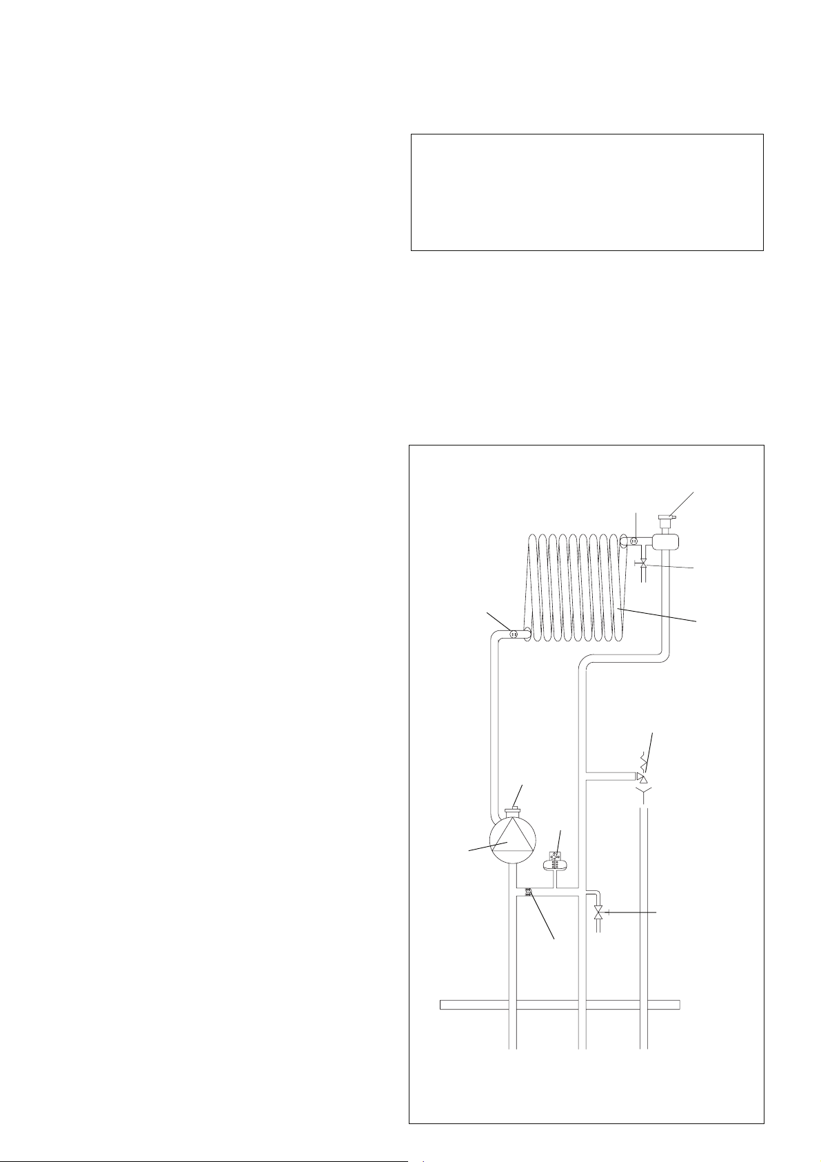
XPAK INTERNAL HYDRAULIC
CIRCUIT (FIG. 2)
MODE OF OPERATION
When there is a request for heat and/or hot water, via the
programmer/time clock and/or any external control, the pump and
fan are started, the fan speed will modulate until the correct signal
voltage
is received at the control PCB. At this point an ignition
sequence is enabled.
Ignition is sensed by the electronic circuitry to ensure flame
stability at the burner. Once successful ignition has been
achieved, the electronic circuitry increases the gas rate to 75% of
the MAX Heating (set by the corresponding HTG trimmer) for a
period of 15 minutes. Thereafter, the boiler’s output will either
increase to maximum or modulate to suit the set requirement.
When the appliance reaches the desired temperature the burner
will shut down and the boiler will perform a three-minute post purge
(timer delay).
When the request for heat has been satisfied the appliance pump
and fan may continue to operate to dissipate any residual heat
within the appliance.
SAFETY DEVICES
When the appliance is in use, safe operation is ensured by:
- a water pressure switch that monitors system water pressure
and will de-activate the pump (when lockout condition is
reached), fan and burner should the system water pressure
drop below the rated tolerance;
- blocked flue switch that monitors flue pressure and will de-
activate
burner should the flue pressure increase over the rated tolerance;
- fan speed sensor to ensure safe operation of the burner;
- a high limit thermostat that over-rides the temperature control
circuit to prevent or interrupt the operation of the burner;
- flame sensor that will shut down the burner when no flame signal
is detected;
- a sensor that interrupts the operation of the appliance if the
condensate pipe becomes blocked;
- a pressure relief valve which releases excess pressure from the
primary circuit;
- a flue sensor that controls the flue temperature continuously
checking to be right according the output;
- a flue thermostat that over-rides the temperature control circuit
to prevent or interrupt the operation of the burner.
the pump (when lockout condition is reached), fan and
temperature
pump
return
sensor
bottom
auto air
valve
pressure
switch
automatic
bypass
flow
temperature
sensor
pressure
relief
valve
drain
valve
top
auto air
valve
manual air
release
main heat
exchanger
12
Fig. 2
Heating
return
Heating
flow
pressure
relief valve
Page 13
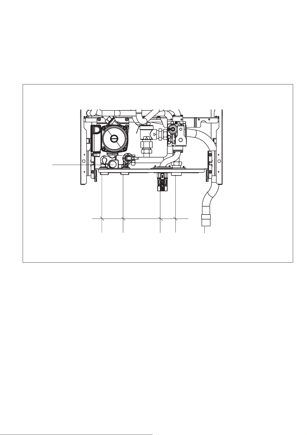
PIPING CONNECTIONS (FIG. 3)
Legend
A - boiler in connection 3/4” NPT - male
B - boiler out connection 3/4” NPT - male
C - gas supply connection 3/4” NPT - female
D - pressure relief valve drain connection 3/4” NPT - female
E - condensate connection Ø (rubber flexible) 0.825” (21 mm) female
F - boiler drain valve - open-ended spanner dimension 7/16” (11 mm)
F
Fig. 3
A
2.55”
65 mm
4.73”
120 mm
B
1.76”
45 mm
CD
E
13
Page 14
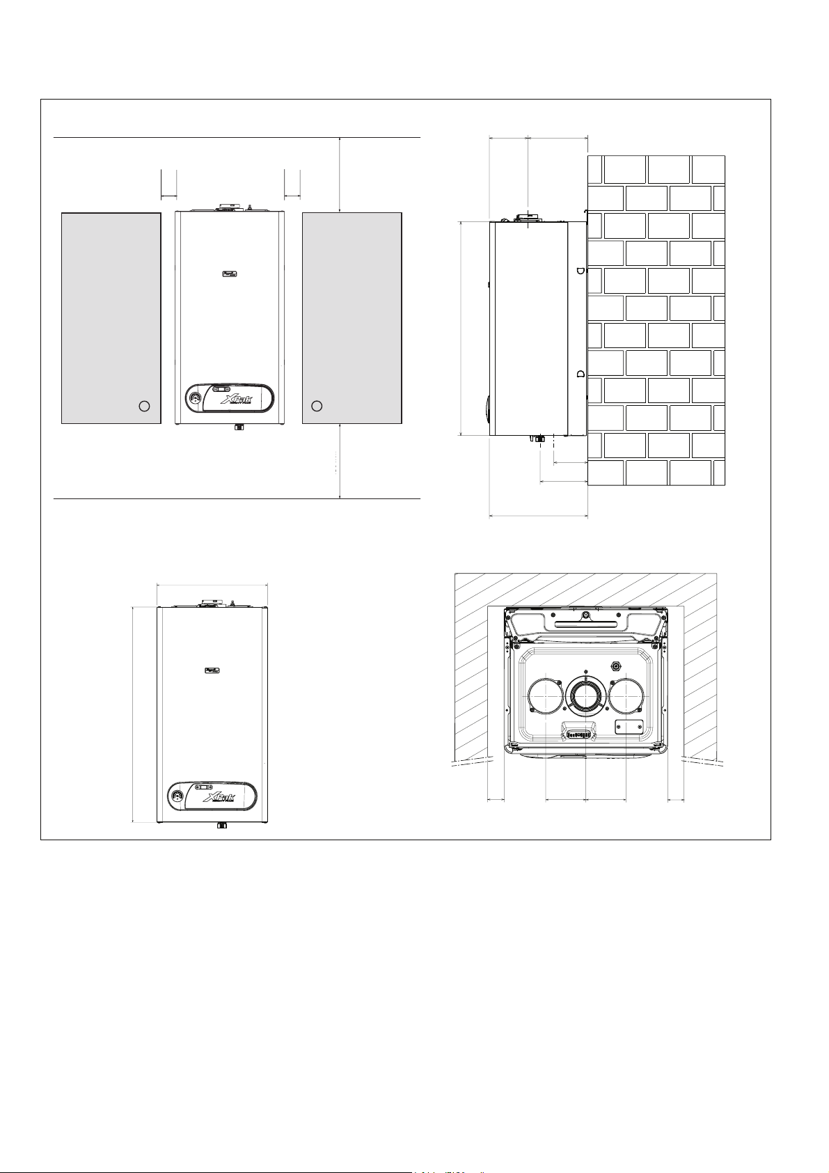
DIMENSIONS AND CONNECTIONS (Fig. 4)
Recommended minimum service clearances
1” (25 mm)
1” (25 mm)
5-1/2”
(140 mm)
12” (300mm)
30-3/4” (781 mm)
6” (150 mm)
14-1/8” (359 mm)
8-5/8”
(219 mm)
water 4-7/8” (124 mm)
gas 6-13/16” (173 mm)
XPak 85 = 15-3/4” (400 mm)
XPak 120 = 17-3/4” (451 mm)
30-3/4” (781 mm)
= =
1” (25 mm)
Fig. 4
1” (25 mm)
XPak 85= 3-15/16“ (97 mm)
XPak 120= 4-1/2“ (114 mm)
Minimum Clearances to Combustibles
Top=0
Front =0 AL, CL
Rear=0
Left=0
Right=0
AL = Alcove
CL = Closet
Note:
The XPak boiler has passed the zero inches vent clearance to combustibles testing requirements provided by the boiler Harmonized
Standard ANSI Z21.13b 2007 – CSA 4.9b 2007 and therefore is listed for zero clearance to combustibles when vented with a single
wall special venting system (AL29-4C material) or UL/ULC-listed gas vent material. The zero inches vent clearance to combustibles
for the XPak boiler supersedes the clearance to combustibles listing that appears on the special venting system label.
14
Page 15
PACKAGING AND TRANSPORTATION
1. SCOPE OF DELIVERY
The boiler is delivered fully assembled.
- When receiving the delivery, check if the packaging is intact.
- Check that all the items listed in Table 2 are included in the
delivery.
2. TRANSPORTING THE BOILER
CAUTION: The boiler may be damaged when it is improperly
secured.
- Only transport the boiler using the right transportation
equipment, such as a handtruck with a fastening belt or
special equipment for maneuvering steps.
- During transportation the boiler must be secured on the
transportation equipment to prevent it from falling off.
- Protect all parts against impacts if they are to be
transported.
- Observe the transportation markings on the packaging.
- Packaged boilers must always be lifted and carried to
their destination by two people, or you must use a handtruck
or special equipment to transport them to their destination.
- Transport the boiler to the room where it is to be installed.
2
1
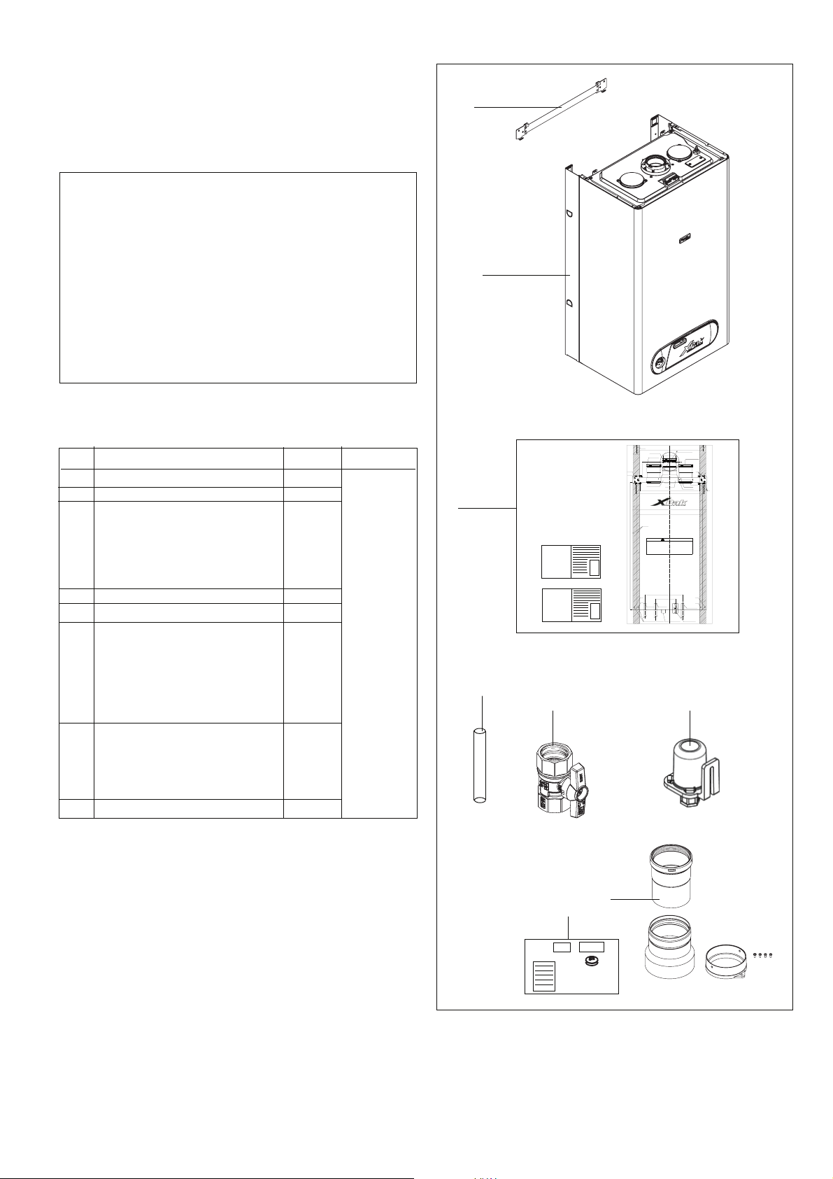
3. BOILER BOX CONTENT (Table 2)
Pos. Parts Quantity Packaging
1 Boiler with casing 1 1 box
2 Wall bracket 1
3 Technical documents 1
including:
- User’s Instructions
- Installation Instructions
- Wall Mounting Template
4 Top manual air vent drain pipe 1
5 Gas shut off valve 1
6 Flue gas adaptors including: 1
- vent adaptor for two pipes
vent system
- intake air adaptor for two pipes
- 3” adaptor
- 4 screws
7 LPG conversion kit 1
- injector black coated
- LPG sticker
- LPG conversion labelling
- Conversion instructions
8 1Outside air sensor
Refer to Fig. 5 for Boiler box contents.
Wall stud
"61 C/C
4,53"Hole for 60/100mm coaxial vent
3" vent adaptor (supplied)
1.5"
inside 3"
Inlet air either right or left
Exhaust vent adapter (supplied)
Screw (2x) (supplied)
14.17"
16.25"
XPak 120 - 17.81"
XPak 85 - 15.75"
C
L
CENTER LINE
OF BOILER
WARNING
This boiler is heavy and awkward to lift. It is
recommended and safer to install the boiler with two
people. Use caution as to not drop this boiler which
could cause personal injury. Verify that the boiler is
securely mounted before leaving the boiler unsupervised.
Ensure there is adequate clearances for mounting the boiler (details given in
installation instructions).
The wall mount bracket is designed for a stud spacing of 16 inches from
center. For other stud spacing a solid mounting surface must be provided by
the installer.
Do not mount the boiler to a hollow wall. Be sure to mount the boiler to the
studs only.
Mount the wall bracket using 4 5/16" lag screws. Ensure the bracket is level
when mounted.
Extreme care is needed to ensure the bolts are secured in the studs.
Hang the boiler on the bracket and secure the bottom of the boiler with two (2)
additional lag screws.
5.90"
3.14"
3.35" 1.38"
NPT male
IN 3/4"
OUT 3/4"
NPT male
Condensate piping exible (supplied)
4/5" female
Ø1/4" holes for earthquake restraint (2 places)
inside 3.15"
Inlet air adapter (supplied)
Screw (2x) (supplied)
Gas shut o valve (supplied)
3/4" NPT female
3" inlet air adapter (not supplied)
Pressure relief valve drain
3/4" NPT female
XPak
120
Screw (2x) (tted)
XPak
85
XPak
120
XPak
85
Boiler bracket
3.54"
(supplied)
Ø1/4" holes
for 5/16" lag
screws (4 places)
3
Boiler outline
30.71" Boiler height
XPak
120
XPak
85
4
5
8
Fig. 5
6
7
15
Page 16

6 - INSTALLATION
PREPARE XPAK LOCATION
1. INSTALLATIONS MUST COMPLY WITH:
- Local, state, provincial, and national codes, laws, regulations
and ordinances.
- National Fuel Gas Code, ANSI Z223.1 – latest edition.
- National Electrical Code.
- For Canada only: B149 Installation Code, CSA C22.1 Canadian
Electrical Code Part 1 and any local codes.
NOTICE: To prevent combustion air contamination when
considering exhaust vent and intake air vent termination.
Intake and exhaust may be vented vertically through the roof
or out a side wall.
The intake and exhaust venting methods are detailed in the
Venting Section. Do not attempt to install the XPak Boiler using any
other means. Be sure to locate the boiler such that the air intake
and exhaust vent piping can be routed through the building and
properly terminated. The air intake and exhaust vent piping
lengths, routing and termination method must all comply with the
methods and limits given in the Venting section.
NOTICE: The XPak boiler gas manifold and controls meet safe
lighting and other performance criteria as specified in ANSI
Z21.13b 2007 – CSA 4.9b 2007
2. BEFORE LOCATING THE XPAK BOILER
1. Check for nearby connection to:
- System water piping
- Venting connections
- Gas supply piping
- Electrical power
2. Check area around boiler. Remove any combustible materials,
gasoline and other flammable liquids.
WARNING: Failure to keep boiler area clear and free of
combustible materials, gasoline and other flammable liquids
and vapors can result in severe personal injury, death or
substantial property damage.
3. The XPak must be installed so that gas control system
components are protected from dripping or spraying water or
rain during operation or service.
4. If the new XPak is to replace an existing boiler, check for and
correct any existing system problems such as:
- System leaks.
- Incorrectly-sized expansion tank.
- Lack of freeze protection in heating water causing system and
boiler to freeze and leak.
- Excessive glycol which will affect the boiler system operation.
3. CLEARANCES FOR SERVICE ACCESS
1. See figure for recommended service clearances. If you do not
provide minimum clearances shown, it might not be possible to
service the boiler without removing it from the space.
WARNING: The space must be provided with combustion/
ventilation air openings correctly sized for all other
appliances located in the same space as the XPak boiler.
The boiler internal front cover must be securely fastened to
the boiler to prevent boiler from drawing air from inside the
boiler room in the case of sealed combustion operation.
This is particularly important if the boiler is located in the
same room as other appliances. Failure to comply with the
above warnings could result in sev ere personal injury, death
or substantial property damage.
4. RESIDENTIAL GARAGE INSTALLATION
Precautions
Take the following special precautions when installing the XPak
in a residential garage. If the boiler is located in a residential
garage, per ANSI Z223.1, paragraph 5.1.9:
- Mount the boiler with a minimum of 18 inches above the floor
of the garage to the bottom of the boiler to ensure the burner
and ignition devices will be no less than 18 inches above the
floor.
- Locate or protect the boiler so it cannot be damaged by a
moving vehicle.
5. EXHAUST VENT AND INTAKE AIR VENT
XPaks are rated ANSI Z21.13b 2007 – CSA 4.9b 2007 – Fired low
pressure steam and hot water boilers. Category IV.(pressurized
vent, likely to condense in the vent). Also installations with air
dependent operation are allowed providing proper openings in
the room are provided.
16
6. PREVENT COMBUSTION AIR CONTAMINATION
Install intake air piping for the XPak as described in the Venting
section. Do not terminate exhaust in locations that can allow
contamination of intake air.
WARNING: You must pipe outside air to the boiler air intake
for sealed combustion operation. Ensure that the intake air
will not contain any of the contaminants below. Contaminated
air will damage the boiler, resulting in possible severe personal
injury, death or substantial property damage. For example, do
not pipe intake air vent near a swimming pool. Also avoid
areas subject to exhaust fumes from laundry facilities. These
areas may contain contaminants.
7. WHEN REMOVING AN EXISTING BOILER FROM AN
EXISTING COMMON VENT SYSTEM
Do not install the XPak boiler into a common vent with any other
appliance.
This will cause flue gas spillage or appliance malfunction, resulting
in possible severe personal injury, death or substantial property
damage.
WARNING: Failure to follow all instructions can result in flue
gas spillage and carbon monoxide emissions, causing severe
personal injury or death.
At the time of removal of an existing boiler, the following steps shall
be followed with each appliance remaining connected to the
common venting system placed in operation, while the other
appliances remaining connected to the common venting system
are not in operation.
a. Seal any unused openings in the common venting system.
b. Visually inspect the venting system for proper size and horizontal
pitch and determine there is non blockage or restriction, leakage,
corrosion and other deficiencies which could cause an unsafe
condition.
c. Insofar as is practical, close all building doors and windows and
all doors between the space in which the appliances remaining
connected to the common venting system are located and other
spaces of the building. Turn on clothes dryers and any appliance
not connected to the common venting system. Turn on any
exhaust fans, such as range hoods and bathroom exhausts, so
they will operate at maximum speed. Do not operate a summer
exhaust fan. Close fireplace dampers.
d. Place in operation the appliance being inspected. Follow the
lighting instructions. Adjust thermostat so appliance will operate
continuously.
e. Any improper operation of the common venting system should
be corrected so the installation conforms with the National Fuel
Gas Code, ANSI Z223.1 — latest edition. Correct by resizing to
approach the minimum size as determined using the
appropriate tables in Table 13 of ANSI Z223.1 2006 of that
code. Canadian installations must comply with B149 Installation
Code.
PREPARE XPAK
CAUTION: CAUTION:
CAUTION: Cold weather handling — If boiler has been
CAUTION: CAUTION:
stored in a very cold location (below 0°F (-18°C)) before
installation, handle with care until the plastic components
come to room temperature.
1. REMOVE XPAK BOILER FROM BOX
1. XPak is heavy and awkward to lift.
Care must be taken to place it in a safe location prior to installation
on the wall to prevent damage to the bottom mechanical
connections.
Page 17

2. PLACING THE WALL-MOUNTED XPAK BOILER
XPak boilers are wall mounted. Use only the XPak boiler wall
mounting instructions included in the box.
WARNING: The wall must be capable of carrying the weight
of the boiler and its related components. The weights of the
boiler are approximately:
XPak 85 = 82 lbs (37 kg).
XPak 120 = 93 lbs (42 kg).
Failure to comply with above could result in severe personal
injury, death or substantial property damage
3. XPAK WALL MOUNTING INSTRUCTIONS
WARNING: This boiler is heavy and awkward to lift. It is
recommended and safer to install the boiler with two people.
Use caution as to not drop the boiler which could cause
personal injury. Verify that the boiler is securely mounted
before leaving the boiler unsupervised.
The wall must be vertically plumb and capable of carrying the
weight of the XPak and its related components.
The building frame (studs) must be 16" on center. If not, you must
use 1/2" minimum plywood 24" x 48", fastened with at least (14)
#12 x 3" (3/16" x 3") round head tapping screws to the frame of the
building to provide proper support for the boiler. Alternate methods
of mounting must not be used. (ex. toggle bolts, hollow wall
anchors) or any other fastener other than #12 x 3" (3/16" x 3") round
head tapping screws.
CAUTION: If the XPak is not vertically plumb, improper and
unsatisfactory operation may occur. This will cause excessive
condensation build-up causing unnecessary maintenance
and nuisance fault codes.
4. INSTALLATION STEPS
Prior to lifting the XPak Boiler onto the wall, use the enclosed
template to level and locate the wall bracket. Mount the wall
bracket using lag screws. Ensure the bracket is level when
mounted. Extreme care is needed to ensure the bolts are secured
in the studs. Hang the boiler on the bracket and secure the bottom
of the boiler with two (2) additional lag screws. This will provide
additional strength and support to the XPak boiler.
XPAK PIPING
1. RELIEF VALVE
The XPak has a pressure relief valve factory fitted.
Connect discharge piping to safe disposal location, following
guidelines in the WARNING below:
WARNING: To avoid water damage or scalding due to relief
valve operation:
- Discharge line must be connected to relief valve outlet and
run to a safe place of disposal. Terminate the discharge line
in a manner that will prevent possibility of severe burns or
property damage should the valve discharge.
- Discharge line must be as short as possible and be the same
size as the valve discharge connection throughout its entire
length.
- Discharge line must pitch downward from the valve and
terminate no more than 6” (150 mm) above the floor drain
where any discharge will be clearly visible.
The discharge line shall terminate plain, not threaded, with
a material serviceable for temperatures of 375 °F (190°C) or
greater.
- Do not pipe the discharge to any place where freezing could
occur.
- Do not plug or place any obstruction in the discharge line.
- Test the operation of the valve after filling and pressurizing
system by lifting the lever. Make sure the valve discharges
freely. If the valve fails to operate correctly, replace it with a
new relief valve.
- For boilers installed with only a pressure relief valve, the
separate storage vessel must have a temperature and
pressure relief valve installed. This relief valve shall comply
with the standard for Relief Valves for Hot Water Supply
Systems, ANSI Z21.22/CSA4.4.
- Failure to comply with the above guidelines could result in
failure of the relief valve to operate, resulting in possibility of
severe personal injury, death or substantial property damage.
2. GENERAL PIPING INFORMATION
CAUTION: Use two wrenches when tightening water piping
at boiler, using one wrench to prevent the boiler return line or
supply line from turning. Failure to support the boiler piping
connections to prevent them from turning could cause damage
to boiler components.
NOTICE: The XPak boiler control module uses temperature
sensors to provide both high limit protection and modulating
temperature control. The PCB also provides low water
protection using a water pressure switch (minimum 6.5 psi
(0.45 bar)) and blocked flue switch. Some codes/jurisdictions
may require additional external controls for high limit and/or
low water cutoff protection.
3. SEPARATE LOW WATER CUTOFF
A low water cutoff may be required by state local code or some
insurance companies. Check code requirements before
installation of the XPak boiler.
If required:
- Use a low water cutoff designed for hydronic installations
- Follow low water cutoff manufacturer’s instructions
NOTICE:
A hot water boiler installed above radiation level or as required
by the Authority having jurisdiction, must be provided with a
low water cut off device either as apart of the boiler or at the
time of the boiler installation.
4. BACKFLOW PREVENTER
Use a backflow preventer specifically designed for hydronic boiler
installations. This valve should be installed on the cold water fill
supply line per local codes.
5. FITTING THE HEATING CIRCUIT SUPPLY AND RETURN
PIPES
NOTICE:
- To protect the entire heating system Raypak recommends
installing a filter in the return circuit. When connecting the
boiler to an existing heating system this filter must definitely
be installed.
- Install shut-off valves immediately before and after the dirt
particle filter to enable the filter to be cleaned.
- Install a filling and drain cock in the heating system supply
pipe if required.
- Also install a safety valve in the system.
NOTICE: When using oxygen-permeable pipes, e. g. for floor
heating systems, you must separate the system using heat
exchangers.
- Thoroughly flush all pipes and radiators.
- Refer to the installation template for the pipe connection
dimensions.
- Connect the pipes so that they are free from strain.
6. EXPANSION TANK AND MAKE-UP WATER
1. Ensure expansion tank size will handle boiler and system
water volume and temperature. Allow 2 gallons for the boiler
and its piping.
CAUTION: Undersized expansion tanks cause system water
to be lost from relief valve and makeup water to be added
through fill valve. Eventual failure can result due to excessive
make-up water addition.
2. Expansion tank must be located near to the boiler as shown
in Piping “XPak installation diagrams”. No valve is to be placed
between the boiler and the expansion tank.
7. SIZING SPACE HEAT SYSTEM PIPING
- Size the piping and components in the space heating system
using recognized design methods.
NOTICE:
- The boiler, when used in connection with a refrigeration
system, must be installed so the chilled medium is piped
in parallel with the boiler and with appropriate valves to
prevent the chilled medium from entering the boiler.
- The boiler piping system of a hot water boiler connected to
heating coils located in air handling units where they may
be exposed to refrigerated air circulation must be equipped
with flow control valves or other automatic means to prevent
gravity circulation of the boiler water during the cooling cycle.
17
Page 18
8. BOILER WITH DHW TANK
- Connect the external hot-water tank according to the Installation
instructions of the hot-water tank and fittings concerned.
Domestic Hot Water Production via DHW Storage Tank
XPak boilers can be used in conjunction with the stand-alone
DHW storage tanks.
The boiler can control the DHW tank temperature directly from
the boiler control panel. In case a tank sensor is installed (see
boiler configuration jumpers Fig. 61) adjust the tank temperature
via the DHW selector. The display shows the tank temperature if
main selector in proper position.
Boiler can accept also a DHW tank controlled by a thermostat
(see boiler configuration jumpers Fig. 61), in this case the DHW
set point can not be adjusted on the control panel but only on the
tank thermostat (field supplied).
Both cases the supplied water temperature to the tank is 176°F
(80°C) and it goes ahead with priority over heating until the tank
request is satisfied (either the sensor or the termostat open).
The boiler can control a 3-way valve directly from the boiler control
panel (see 3-way installations Fig. 38).
Refer to electrical connections for 3-way valve installation.
Size and select the DHW storage tank based on the forecast
DHW consumption of the building in question.
If different method of DHW production are used, the boiler flow
temperature is set as heating mode (see boiler configuration
jumpers Fig. 61).
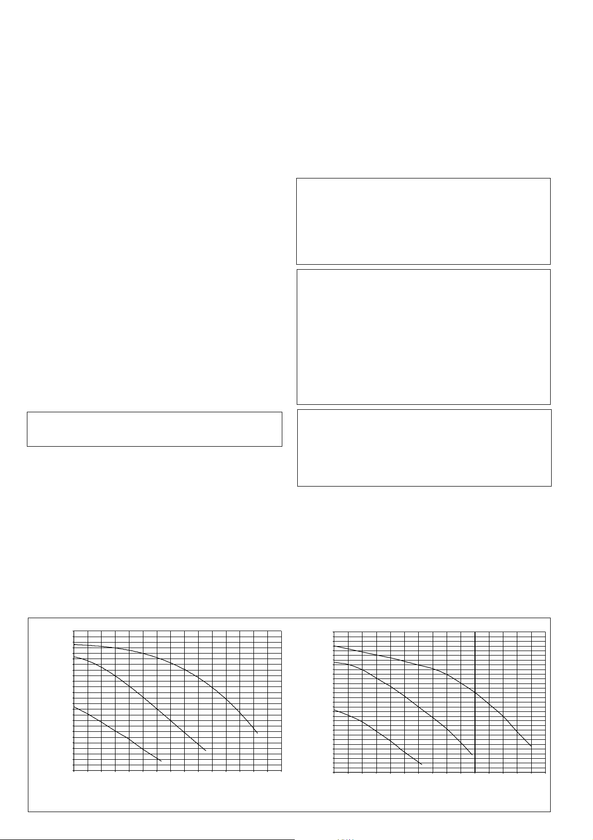
9. WATERSIDE FLOW (PRIMARY CIRCUIT)
The boiler is designed only for closed loop, forced circulation hot
water heating systems.
XPak is equipped with an internal 3 speed pump.
PUMP DUTY
Fig. 6 below shows the flow-rate available – after allowing for
pressure loss through the appliance – for system requirements.
When using this graph, apply only the pressure loss of the system.
The graph is based on a 36°F (20°C) temperature differential.
required system volume and capacity, no valve is to be placed
between the boiler and the expansion tank.
6. Install an Air Elimination Device on the system supply if
required, the boiler has two auto air vents built in.
7. Install a drain valve at the lowest point of the system.
Note: The XPak has a proper internal drain valve. (see Fig.
42a)
8. The Safety Relief Valve is installed at the factory. Pipe the
discharge of the safety relief valve to prevent injury in the
event of pressure relief. Pipe the discharge to a maximum of
6” (152 mm) above the floor to a drain. Provide piping that is
the same size as the safety relief valve outlet. Never block the
outlet of a safety relief valve.
11. FILL AND PURGE HEATING SYSTEM
CAUTION: For installation that incorporates standing Iron
Radiation and systems with manual vents at the high points.
Follow above section and starting with the nearest manual air
vent, open vent until water flows out, then close vent. Repeat
procedure, working your way toward furthest air vent. It may
be necessary to install a basket strainer in an older system
where larger amounts of sediment may be present. Annual
cleaning of the strainer may be necessary.
WARNING: Use only inhibited propylene glycol solutions
which are specially formulated for hydronic systems. Ethylene
glycol is toxic and can attack gaskets and seals used in
hydronic systems. Glycol mixtures should not exceed 40%.
1.Glycol in hydronic applications which is specially formulated
for this purpose includes inhibitors that prevent the glycol
from attacking metallic system components. Make certain
that the system fluid is checked for the correct glycol
concentration and inhibitor level.
2.The glycol solution should be tested at least once a year and
as recommended by the glycol manufacturer.
3.Anti-freeze solutions expand more than water. Allowances
must be made for this expansion in the system design.
CAUTION: The XPak should not be operated as a potable
Hot Water Boiler. The XPak should not be operated in a open
system.
10. PROCEDURE SUMMARY
1. Connect the system return marked “In”.
2. Connect the system supply marked “Out”.
3. Install a Back Flow preventor on the Cold Feed Make-Up
Water line.
4. Install a Pressure Reducing Valve if required on the Cold
Feed Make-Up Water line, 15 PSI (1 bar) nominal on the
system return. Check Pressure Gauge which should read
minimum pressure of 12 PSI (0.8 bar)
5. Install an Expansion Tank on the system supply. Consult the
tank manufacturer’s instruction for specific information relating
to expansion tank installation. Size the expansion tank for the
16
15
14
12
11
10
9
7
6
5
3
Residual head (ftwc)
2
0.6
0
0 20 41 61 81 102 122 142 163 183 203 224 244 264 285 305
XPak 85
3rd speed
2nd speed
1st speed
Flow rate (gph)
Fig. 6
CAUTION: It is highly recommended that you carefully follow
the glycol manufacturer’s recommended concentrations,
expansion requirements and maintenance recommendations
(pH additive breakdown, inhibitor reduction, etc.). You must
carefully calculate the additional friction loss in the system as
well as the reduction in heat transfer co-efficients; pH must be
maintained between 6-8.
16
15
14
12
11
10
9
7
6
5
3
Residual head (ftwc)
2
0.6
0
0 20 41 61 81 102 122 142 163 183 203 224 244 264 285 305
XPak 120
3rd speed
2nd speed
1st speed
Flow rate (gph)
18
Page 19
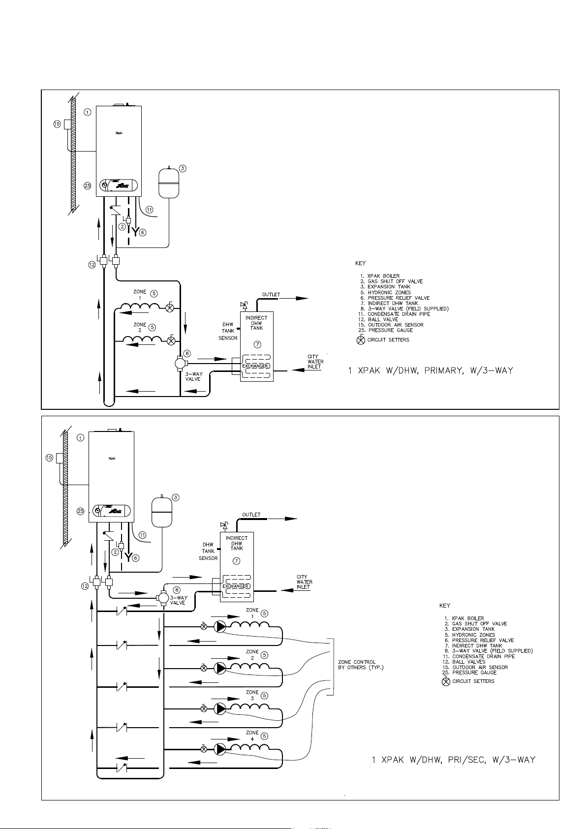
XPAK INSTALLATION DIAGRAMS
NOTICE: The following illustrations are simplified conceptual
illustrations only.
Fig. 7
Fig. 8
19
Page 20
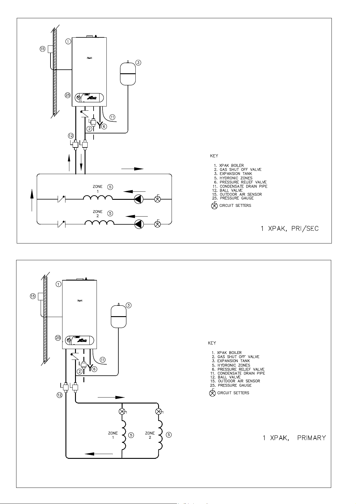
Fig. 9
Fig. 10
20
Page 21
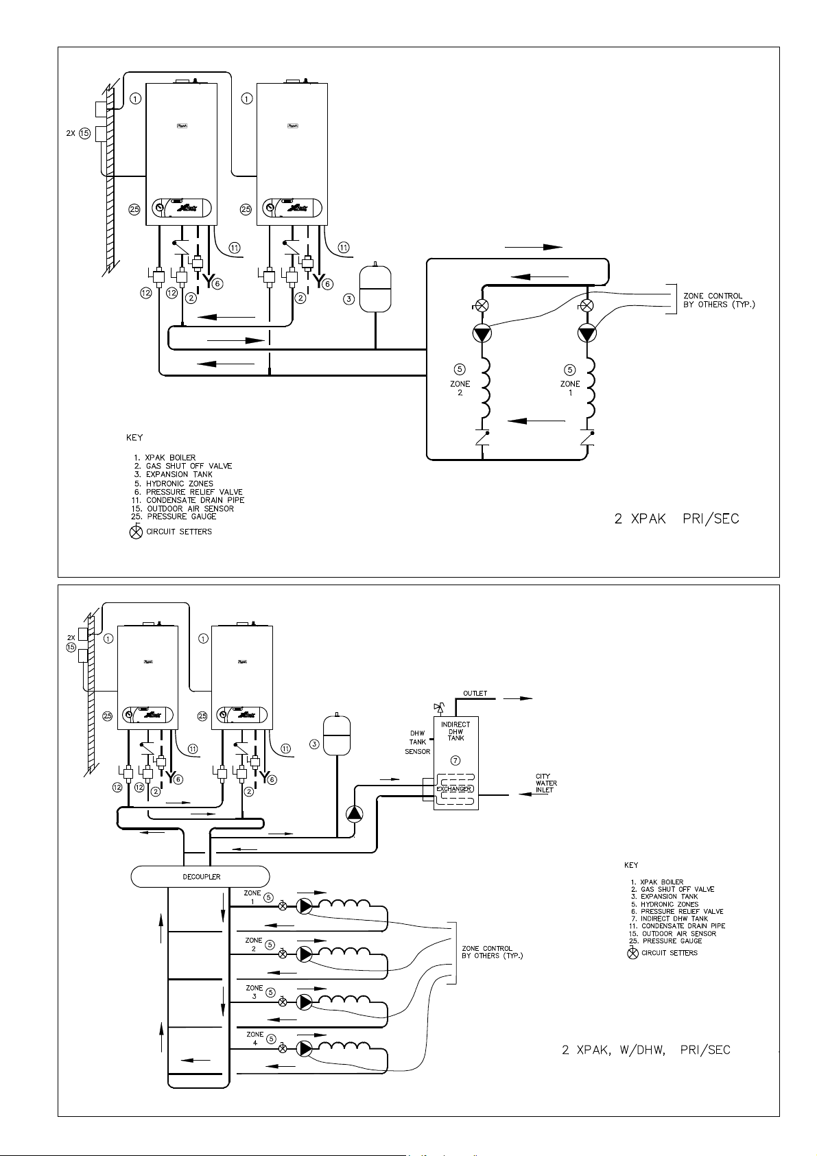
Fig. 11
Fig. 12
21
Page 22

MAKING THE GAS CONNECTION
DANGER: Only carry out work on gas conduits and fittings if
you are licensed for such work.
- Determine proper size gas pipe for the installation using
Table 3 and
and observe proper size of the fittings.
- Install the furnished 3/4” female gas cock on the gas
connection (3/4” male on the boiler) (Fig. 13).
- Connect the gas pipe to the gas cock so that it is free from
any strain.
CAUTION: The boiler and its individual shutoff valve must
be disconnected from the gas supply piping system during
any pressure testing of that system at test pressures in excess
of 1/2 psi (3.5 kPa).
Fig. 13
A- Manual main gas shutoff
valve (supplied)
B- Coupling (field supplied)
C- To gas supply
Table 4. Do not forget the pipe fitting losses
A
B
C
position
Fig. 14
Open
Closed
position
NOTICE: When installing the gas supply connection, it must
comply with local regulations or, if such regulations do not e xist,
with the National Fuel Gas Code, ANSI Z 223.1.
In Canada, the gas supply connection must comply with local
regulations or, if such regulations do not exist, with CAN/CSA
B149, Natural Gas and Propane Installation Code. A sediment
trap must be provided upstream of the gas controls.
Gas Pipe Capacity for different pipe sizes
Length of Gas Volume Capacity
pipe (feet) (ft3/h)
*
Ta b . 3
3/4” 1” 1 1/4” 1 1/2”
10 278 520 1,060 1,600
20 190 350 7 3 0 1,100
30 152 285 590 890
40 130 245 500 760
50 115 215 440 670
75 93 175 360 545
100 7 9 160 305 480
150 6 4 120 250 380
* Maximum pipe capacity in ft3/hr, based on a specific gravity of 60 (42
mbar) and a inlet gas pressure of 14 inches W.C. (35 mbar) or less and a
pressure drop of 0.3 inches W.C. (20 mbar)
Equivalent length for pipe fittings in feet
Ta b. 4
Steel pipe Equivalent length for Pipe Fittings in feet
diameter Type of pipe fitting
in inches 90° Elbow Tee Gate valve Gas cocks
(flow thru
branch)
Equivalent length in feet
3/4 2.1 4.1 0.5 1.25
1 2.6 5.2 0.6 1.60
1 1/4 3.5 6.9 0.8 2.15
1 1/2 4.0 8.0 0.9 2.50
NOTICE: The boiler must be isolated from the gas supply
piping system by closing its individual manual shutoff valve
during any pressure testing of the gas supply piping system at
test pressures equal to or less than 1/2 psi (3.5 kPa).
22
Page 23

BOILER TEMPLATE (Fig. 15)
Boiler bracket
(supplied)
Ø1/4" holes
for 5/16" lag
screws (4 places)
1.5"
Wall stud
3.54"
Exhaust vent adapter (supplied)
3" vent adaptor (supplied)
Inlet air either right or left
C/C16"
inside 3"
Screw (2x) (supplied)
14.17"
16.25"
XPak 120 - 17.81"
XPak 85 - 15.75"
4,53" Hole for 60/100mm coaxial vent
3" inlet air adapter (not supplied)
inside 3.15"
Screw (2x) (supplied)
Inlet air adapter (supplied)
XPak
120
Screw (2x) (fitted)
Wall Mounting Information
XPak comes with a template,
which allows you to easily mark
the location of the screws for the
mounting bracket and the location
of the flue gas pipe on the wall
(Raypak coaxial PP vent system
only).
The connection to the gas circuits
must be made on site, 3/4” gas
cock is supplied with the boiler .
XPak
85
30.71" Boiler height
C
Boiler outline
CENTER LINE
OF BOILER
This boiler is heavy and awkward to lift. It is
recommended and safer to install the boiler with two
people. Use caution as to not drop this boiler which
could cause personal injury. Verify that the boiler is
securely mounted before leaving the boiler unsupervised.
Ensure there is adequate clearances for mounting the boiler (details given in
installation instructions).
The wall mount bracket is designed for a stud spacing of 16 inches from
center. For other stud spacing a solid mounting surface must be provided by
the installer.
Do not mount the boiler to a hollow wall. Be sure to mount the boiler to the
studs only.
Mount the wall bracket using 4 5/16" lag screws. Ensure the bracket is level
when mounted.
Extreme care is needed to ensure the bolts are secured in the studs.
Hang the boiler on the bracket and secure the bottom of the boiler with two (2)
additional lag screws.
L
WARNING
XPak
120
XPak
85
IN 3/4"
NPT male
Ø1/4" holes for earthquake restraint (2 places)
5.90"
OUT 3/4"
3.35" 1.38"
NPT male
Condensate piping flexible (supplied)
0.825” female
4/5" female
3.14"
Pressure relief valve drain
3/4" NPT female
Gas shut off valve (supplied)
3/4" NPT female
XPak
120
XPak
85
Fig. 15
23
Page 24

COMBUSTION AIR AND
VENTILATION OPENINGS
Provisions for combustion and ventilation air must be made in
accordance with section 5.3, Air for Combustion and Ventilation,
of the National Flue Gas Code, ANSI Z223.1, or Sections 7.2, 7.3
or 7.4 of CAN/CGA B149, Installation Codes, or applicable
provisions of the local building codes.
CAUTION: BOILER DAMAGE AND OPERATIONAL
FAILURES !
Due to insufficient or lacking openings for combustion air
and/or ventilation of the boiler room. Provisions for
combustion air and ventilation are always required,
regardless whether the combustion air is taken from the
outside (sealed combustion) or inside (room air for
combustion). Insufficient ventilation of the boiler room can
lead to high air temperatures.
This can result in boiler damage.
– Make sure that intake and exhaust openings are sufficiently
sized and no reduction or closure of openings takes place.
– When the problem is not resolved, do not operate the boiler.
– Please note these restrictions and its dangers to the operator
of the boiler.
WARNING: BOILER DAMAGE !
Due to contaminated air.
– Boiler must be clear and free from combustible materials,
gasoline and other flammable vapors and liquids, and
corrosive liquids and vapors. Never use chlorine and
hydrocarbon containing chemicals (such as spray
chemicals, solution and cleaning agents, paints, glues etc)
in the vicinity of the boiler.
– Do not store and use these chemicals in the boiler room.
– Avoid excessive dust formation and build-up.
NOTICE: When one expects contaminated combustion air
(near swimming pools, chemical cleaning operations and
hair salons), sealed combustion operation is recommended.
DANGER: FIRE DANGER !
Due to flammable materials or liquids.
– Do not store flammable materials and liquids in the
immediate vicinity of the boiler.
All Air from Inside the Building (room air)
The room shall be provided with two permanent openings
communicating directly with an additional room(s). The total input
of all gas utilization equipment installed in the combined space
shall be considered in making this determination. Each opening
shall have a minimum free area of 1 square inch per 1,000 Btu per
hour of total input rating of all gas utilization equipment in the
confined space, but no less than 100 square inches. One opening
shall commence within 12 inches (305 mm) of the top, and one
opening shall commence within 12 inches (305 mm) of the bottom
of the enclosure. The minimum dimension of air openings shall be
not less than 3 inches (75 mm).
All Air from Outdoor (sealed combustion)
The room shall be provided with two permanent openings, one
commencing within 12 inches (305 mm) from the top, and one
commencing within 12 inches (305 mm) from the bottom of the
enclosure. The openings shall communicate directly, or by ducts,
with the outdoors or spaces (crawl or attic) that freely communicate
with the outdoors.
The minimum dimension of air openings shall be no less than 3
inches (75 mm).
1. Where directly communicating with the outdoors, each opening shall have a minimum free area of 1 square inch per 4,000
Btu/hr of total input rating of all equipment in the enclosure.
2. Where communicating with the outdoors through vertical ducts,
each opening shall have a minimum free area of 1 square inch
per 4,000 Btu/hr of total input rating of all equipment in the
enclosure.
3. Where communicating with the outdoors through horizontal
ducts, each opening shall have a minimum free area of 1 square
inch per 2,000 Btu/hr of total input rating of all equipment in the
enclosure.
4. Where ducts are used, they shall be of the same cross-sectional
area as the free area of the opening to which they connect.
INSTALLATION OF THE EXHAUST
AND AIR INTAKE SYSTEM
NOTICE: Consult local and state codes pertaining to special
building code and fire department requirements. Adhere to
national code requirements.
NOTICE: Observe the listed maximum lengths of vent system,
which are boiler model dependent. The maximum permissible
lengths are listed in the main specification Tab. 5.
An optional concentric vent/air intake body can be used for the
installation of a vertical venting system as well as for a horizontal
venting system. The concentric vent/air intake body can be ordered
through Raypak Inc.
The boiler can also be operated with separate air intake and
exhaust piping.
The termination shall be at least 4 ft (1220 mm) for the U.S. and
6ft. (1830 mm) for Canada away from a gas utility meter, service
regulator or the like (for room air applications only).
The termination shall terminate at least 4 ft (1220 mm) below, 4 ft
(1220 mm) horizontally from, or 1 ft (305 mm) above any door,
window, or gravity air inlet into any building.
Vent must be at least 12 inches (305 mm) above grade, anticipated
snow line or roof surface (Canada 18” (457 mm) minimum).
Vent termination must be at least 7 ft (2135 mm) above a public
walkway (see Fig. 20).
Vent must be 3 ft (915 mm)above any forced air intake within 10
ft (3050 mm) (see Fig. 20).
Do not extend exposed vent pipe outside the building beyond
recommended distance. Condensate could freeze and block vent pipe.
Vent should terminate at least 3 ft (915 mm) away from adjacent
walls, inside corners and below roof overhang.
It is not recommended to terminate vent above any door or
window, condensate can freeze causing ice formations.
Do not use chimney as a raceway if another boiler or fireplace is
vented into or through chimney.
All vent pipes must be glued, except for the flue gas adapter which
is fix into place and the first connection to the flue gas adapter.
Installed you can slide the pipe onto the adapter, properly supported
and the exhaust pipe must be pitched a minimum of a ¼ inch per
foot back to the boiler. This allows the condensate to drain away.
NOTICE:
- Do not use cellular core pipe.
- A minimum clearance of 4 feet horizontally from and in no case
above and below, unless a 4-foot horizontal distance is
maintained, from electric meters, gas
Below are approved examples of vertical and horizontal venting
installation
- Place pipe supports every 5 feet (1525 mm) of horizontal run,
beginning with support near boiler.
- Periodic cleaning of the vent terminal and air-intake screens is
mandatory.
- The minimum covering wall thickness is 1" (25 mm).
- The maximum covering wall thickness is 16" (406 mm).
- For Direct venting properly reassembele and reseal the vent
and air-intake systems.
CAUTION: Vent connectors serving appliances vented by
natural draft shall not be connected into any portion of
mechanical draft systems operating under positive pressure.
Fig. 15A
24
Page 25

VENT SYSTEMS
1. FLUE GAS SYSTEM
Raypak coaxial PP (Polypropylene/Aluminium) concentric flue
gas/fresh air systems, Raypak coaxial Alu/Alu concentric flue
gas/fresh air systems and two-pipe aluminum systems for room
air independent operation (sealed combustion) and air
dependent operation and side wall venting are tested to ANSI
ANSI Z21.13b 2007 – CSA 4.9b 2007 standards and are certified
together with the XPak boiler as a constructional unit.
The XPak boiler may also be vented vertically or horizontally,
using a metallic AL29-4C
sources: ProTech System Inc., or room air dependent venting
system (UL/ULC listed for category IV).
For a more detailed description of the direct vent and single-wall
vent system, please refer to the following installation Instructions.
See Fig. 32A (pg. 33) for special instructions on XPak 85 boilers.
NOTICE:
Brick or masonry surfaces directly behind the horizontal vent
termination should be protected with a rust-resistant sheet
metal plate.
Tab. 5
Country US + CANADA
Diameter 3”
Material Stainless steel
Single wall Maximum Equivalent Length 3” (80 mm)
Horizontally/
vertically
vented
(air+flues)
®
special stainless steel - Suggested
FasNseal
stainless steel vent
XPak 85
40+40ft
12+12m
XPak 120 XPak 85 XPak 120
16+16
5+5
De-rate less 5%De-rate less 2%
130+130 115+115
40+40 35+35
1
2
Fig. 16
3
4
5
A
B
A
1 Gasket in EPDM (peroxide) -58°F (-50°C) – 302°F (150°C)
2 Adapter in PP (polypropylene) male/female 80 mm > 3”
6
Always follow XPak Installation Instructions.
Select vent material based on
- Country of the installation
- Vent configuration
- Preferred material
- Necessary maximum equivalent length
NOTICE:
The minimum covering wall thickness is 1” (25 mm)
The maximum covering wall thickness is 16” (406 mm)
2. BOILER SUPPLY
XPak boilers are supplied with the following vent components and they
are certified together with the XPak boiler as a constructional unit.
- 60/100 mm vent exit (Fig. 16 pos. 1)
- Left side intake air (factory sealed with two screws) for two pipes
solutions (Fig. 16 pos. 2)
- Right side intake air (factory sealed with two screws) for two
pipes solutions (Fig. 16 pos. 3)
- Vent adaptor for two pipes vent system – 80 mm dia exit (Fig. 16
pos. 5) (Fig. 19)
- Intake air adaptor for two pipes vent system – 80 mm dia exit (Fig.
16 pos. 6) (Fig. 18)
- 3” adaptor (inside diameter 3”) (Fig. 16 pos 4, Fig. 17)
- Paper template to fix the boiler and the flues (Fig. 15)
3. INSTALLATIONS OF SUPPLIED VENT COMPONENTS
In the case of installations using two pipes or room dependent air
the following instructions must be observed.
1. Install the vent adapter (Fig. 19) to the boiler vent connection
(Fig. 16 pos. 1)
2. Use the two supplied screws to ensure the closing between
the adapter and boiler (Fig. 16 pos. 5)
3. Insert the 3” adapter (Fig. 17) into the vent adapter (Fig. 19) in
the case using 3” vents
4. Install the air adapter (Fig. 18) to the boiler air connection (choose
right or left installation (Fig. 16 pos. 2 - 3), using the two supplied
screws (Fig. 16 pos. 6) in the case of two pipes, room sealed vent
installation.
Fig. 17
Fig. 18
Fig. 19
25
Page 26

4. MINIMUM CLEARANCES FROM VENT/AIR INLET TERMINATION
Fig. 20
V = vent terminal X = air supply inlet \\\ = area where terminal is not permitted
Tab. 6
U.S. Installations1 Canadian Installations2
A Clearance above grade, veranda,
porch, deck, or balcony 1 ft (30 cm) 1 ft (30 cm)
B Clearance to window or door that may 4 ft (1.2m) below or to side of
be opened opening; 1 foot (30 cm) above 3 ft (91 cm)
opening
C Clearance to permanently closed window * *
D Vertical clearance to ventilated soffit located above 5 ft (1.5m) *
the terminal within a horizontal distance of 2 ft (61cm)
from the centerline of the terminal
E Clearance to unventilated soffit **
F Clearance to outside corner **
G Clearance to inside corner 6 ft (1.83m) *
H Clearance to each side of center line * 3 ft (91 cm) within a height
extended above meter/regulator assembly 15 ft above the meter/ regulator
assembly
I Clearance to service regulator vent outlet * 6 ft (1.83m)
J Clearance to non-mechanical air supply inlet to 4 ft (1.2m) below or to 3 ft (91 cm)
building or the combustion air inlet to any other side of opening; 1 ft
appliance (30 cm) above opening
K Clearance to mechanical air supply inlet 3 ft (91 cm) above if within 6 ft (1.83m)
10 ft (3m) horizontally
L Clearance above paved sidewalk or paved driveway 7 ft (2.13m) 7 ft (2.13m) t
located on public property
M Clearance under veranda, porch, deck or balcony * 12 in. (30 cm) TT
1 In accordance with the current ANSI Z223.1/NFPA 54 National Fuel Gas Code
2 In accordance with the current CAN/CGA-B149 Installation Codes
t Vent terminal shall not ter minate directly above sidewalk or paved driveway located between 2 single family dwellings that ser ves both dwellings
TT Permitted only if veranda, porch, deck, or balcony is fully open on a minimum of two sides beneath the floor and top of terminal and underside
of veranda, porch, deck or balcony is greater than 1 ft (30cm)
* Clearances in accordance with local installation codes and the requirements of the gas supplier
26
Page 27

NOTICE: The following illustrations are simplified conceptual
illustrations only.
Legend for illustrations 23-24-25-26-27-28-29-30-31-32
Two pipes vent adaptors (included with the boiler) Pos. 1
Mounting Clip (set of 4) 3.94” (100 mm) for coaxial Pos. 2 (Fig. 24)
90° Elbow 3” (80 mm) single wall Pos. 2 (Fig. 25-26-27-28)
Adaptor 80 mm > 3” (included with the boiler 1 pcs) Pos. 2 (Fig. 29-30-31-32)
45° Elbow 3” (80 mm) single wall Pos. 3 (Fig. 25-26-28)
V ertical vent termination 3.28 ft (1 m) 3.94” (100 mm) coaxial Pos. 3
Straight Pipe 1.64 ft (0.5 m) 3” (80 mm) single wall Pos. 4 (FIg. 25-26-28)
Roof Flashing flat universal Pos. 4 (Fig. 23)
Straight Pipe 3.28 ft (1 m) 3” (80 mm) single wall Pos. 5
Straight Pipe 6.56 ft (2 m) 3” (80 mm) single wall Pos. 6 (Fig. 28)
Roof Flashing sloping universal Pos. 6 (Fig. 24)
45° Elbow 3.94” (100 mm) coaxial Pos. 7
Horizontal inlet air vent 2.82 ft (0.86 m) 3” (80 mm) single wall Pos. 8 (Fig. 25-26-27)
Straight Pipe 1.64 ft (0.5 m) 3.94” (100 mm) coaxial Pos. 8 (Fig. 24)
Adaptor for room air dependent operation Pos. 9 (Fig. 28)
Straight Pipe 3.28 ft (1 m) 3.94” (100 mm) coaxial Pos. 9 (Fig. 24)
90° Elbow 3.94” (100 mm) coaxial Pos. 10 (Fig. 24)
Mounting Clip (set of 4) Pos. 10 (Fig. 25-26-27-28)
Vertical vent termination 3” (80 mm) single wall Pos. 11
Fig. 23
SEALED COMBUSTION OPERATION
VERTICAL COAXIAL
Fig. 24
VERTICAL COAXIAL
SEALED COMBUSTION OPERATION
27
Page 28

Fig. 25
a = total intake length = INTAKE
b = total flue length = EXHAUST
TWO PIPES SINGLE WALL
SEALED COMBUSTION OPERATION
Fig. 26
a = total intake length = INTAKE
b = total flue length = EXHAUST
TWO PIPES SINGLE WALL
SEALED COMBUSTION OPERATION
28
Page 29

Fig. 27
a = total intake length = INTAKE
b = total flue length = EXHAUST
TWO PIPES SINGLE WALL
SEALED COMBUSTION OPERATION
Fig. 28
a = total intake length = 0
b = total flue length = EXHAUST
TWO PIPES SINGLE WALL
ROOM AIR DEPENDENT OPERATION
a = 0
29
Page 30

Stainless Steel 3” Vent System
1
US + CANADA
Vent System - Room Air independent Operation (Sealed Combustion Operation) - Fig. 12-14-15-17
Tab. 7
Vent System diameter 3”
Vent system material Stainless steel
Two pipes vent adaptors (included with the boiler) - adaptor 80 mm > 3” (included with the boiler 1 pcs) for flue - adaptor 80 mm > 3” for intake air Field supplied Order No.
Combustion air intake vent material
ULC/UL listed
1
Stainless steel Vent material
45° elbow EqL = 2 ft / 0,6m Field supplied Order No.
90° elbow EqL = 3 ft / 0,9m
Bird Screen c/w Termination Field supplied Order No.
Venting support
1
stainless steel vent material must be ULC/UL listed, stainless steel AL29-4C® for category IV boilers. Sources FasNseal – Protech
System Inc.
2
Order Mounting Clip for each straight length of vent pipe installed, boiler can not support weight of vent system
3
allowable material for combustion air ABS – CPVC – PVC or stainless steel
2
dia. 3” Field supplied Order No.
- Do not exceed maximum equivalent vent length.
- Always follow XPak Venting System Installation Instructions.
3
Field supplied Order No.
Stainless Steel Vent System
1
US + CANADA
Vent System - Room Air Dependent Operation - Fig. 13-16-18
Vent System diameter 3”
Vent system material Stainless steel
Adaptor for room air dependent operation
adaptor 80 mm > 3” (included with the boiler 1 pcs) - ULC/UL listed
1
Stainless steel Vent material
45° elbow EqL = 2 ft / 0,6m Field supplied Order No.
90° elbow EqL = 3 ft / 0,9m
Bird Screen c/w Termination Field supplied Order No.
2
Venting support
1
Stainless steel vent material must be ULC/UL listed, stainless steel AL29-4C® for category IV boilers. Sources FasNseal –
Protech System Inc.
2
Order Mounting Clip for each straight length of vent pipe installed, boiler can not support weight of vent system
3
Provide a proper air opening in the room (size according indication pg. 7)
dia. 3” Field supplied Order No.
- Do not exceed maximum equivalent vent length.
- Always follow XPak Venting System Installation Instructions.
3
013102 Order No.
Tab. 8
30
Page 31

DESCRIPTION DIAGRAM DRAWING
P/N 013040
Two pipes vent adaptors Fig. 29-30-31-32
(included with the boiler) Pos. 1
P/N 013040
adaptor 80 mm > 3” Fig. 29-30-31-32
(included with the boiler 1 pcs) Pos. 2
Fig. 29
a = total intake length = INTAKE
b = total flue length = EXHAUST
TWO PIPES SINGLE WALL
SEALED COMBUSTION OPERATION
31
Page 32

Fig. 30
a = total intake length = INTAKE
b = total flue length = EXHAUST
TWO PIPES SINGLE WALL
SEALED COMBUSTION OPERATION
Fig. 31
a = total intake length = INTAKE
b = total flue length = EXHAUST
TWO PIPES SINGLE WALL
SEALED COMBUSTION OPERATION
32
Page 33

Fig. 32
a = total intake length = 0
b = total flue length = EXHAUST
TWO PIPES SINGLE WALL
SEALED COMBUSTION OPERATION
Fig. 32A
XPAK 85 ONLY:
If using two pipe single-wall
sealed combustion with
CPVC vent, add
polypropylene adapters
as shown. Field-supplied.
33
Page 34

CONNECTING THE CONDENSATE
WATER DRAIN
Install the condensate drain flexible pipe (Ø 0.825” - 21mm
female flexible rubber connection) with a suitable gradient (min.
2.5%).
Discharge condensate from the boiler into the drainage system,
either directly or (if required) via a neutralization unit (not
supplied).
1. CONDENSATE CONNECTION
The condensate drain of the boiler is equipped with a built-in
siphon trap in order to keep flue gases from being discharged
via the condensate drain.
The condensate formed both in the condensing boiler and in the
flue gas pipe must be discharged into the public sewage system
in accordance with all applicable local regulations.
The condensate produced by a gas-fired heating system has a
pH value between 3 and 4.
Some local codes may require the use of a separate neutralization
unit to treat the aggressive and corrosive condensate.
Raypak offers a Condensate Neutralizer Kit (Z-12 option) for use
when managing the condensate is desired or required. Order
part number 013141.
With a neutralization unit installed, all condensate from the boiler
and the flue gas pipe enters into the neutralization unit where it
is treated and released into the public sewage system with a
safe pH value of above 6.5.
The use of neutralization granulate (performing the neutralizing
process) is dependent on the operation of the heating system.
To deter mine the required refill amount, check granulate level
several times during the first year of operation. In some cases
one granulate fill may last an entire year.
The condensate discharge outlet to the drainage system
connection must be clearly visible. It must be installed with a
suitable gradient and provided with a stench trap.
If the condensate outlet of the boiler is lower than the drain, a
condensate pump must be used (see electrical wiring to loch out
the boiler in the case of failure of the condensate pump - alarm 21).
Only corrosion-resistant materials may be used for condensate
drainage purposes (e.g. braided hose). Do not use galvanized
materials or materials containing copper for piping, couplings etc.
Please note that other requirements may apply depending on
local regulations and/or project-specific details.
It is advisable to contact your local waterworks office (authority
responsible for waste water regulations) well before
commencing with the installation of the neutralization unit in order
to establish details of local regulations that apply.
NOTICE: Pipe ventilation must take place between the
siphon trap and the neutralization unit (if applicable).
7 - ELECTRICAL CONNECTIONS
Devices such as outdoor sensor, 3-way valve, tank sensor, tank
thermostat, remote controls are all connected to the external
connection board.
The electrical connections to the boiler must be made in
accordance with all applicable local codes and the latest revision
of the National Electrical Code, ANSI/NFPA-70.
Installations should also conform with CSA C22.1 Canadian
Electrical Code Part 1 if installed in Canada.
1. EXTERNAL CONNECTION BOARD CONNECTIONS
A qualified electrician should connect the electrical supply to the
appliance. If controls – external to the appliance – are required,
a competent person must undertake the design of any external
electrical circuits. ANY EXTERNAL CONTROL OR WIRING MUST
BE SERVED FROM THE SAME ISOLATOR AS THAT OF THE
APPLIANCE. Wiring to the appliance must be rated for operation
in contact with surfaces up to 194°F (90°C).
WARNING: ELECTRICAL SHOCK HAZARD — For your
safety, turn off electrical power supply at service entrance
panel before making any electrical connections to avoid
possible electric shock hazard. Failure to do so can cause
severe personal injury or death.
AVERTISSEMENT: RISQUE DE CHOC ÉLECTRIQUE —
Pour votre sécurité, coupez l'alimentation électrique au niveau
du tableau de distribution avant d'effectuer tout raccordement
électrique afin d'éviter un risque éventuel de choc électrique.
La non-observation du dernier point peut provoquer de
graves blessures ou la mort.
NOTICE: Wiring must be N.E.C. Class 1. If original wiring as
supplied with heater must be replaced, use only TEW 221°F
(105 °C) wire or equivalent. Heater must be electrically
grounded as required by National Electrical Code ANSI/
NFPA 70 — latest edition.
CAUTION: Label all wires prior to disconnection when
servicing controls. Wiring errors can cause improper and
dangerous operation.
Verify proper operation after servicing.
2. ELECTRICAL SUPPLY
The boiler requires a 120V 60Hz power supply. Ensure the
electrical supply is properly polarized.
The boiler must be grounded.
There must only be one common isolator, providing complete
electrical isolation for the boiler and any external controls using
PVC insulated cable 18 AWG x3C 105 °C /221°F.
All wiring must be installed in accordance with requirements of
National Electrical Code and any additional national, state, or
local code requirements having jurisdiction. All wiring must be
N.E.C. Class 1. The boiler must be electrically grounded in
accordance with the National Electrical Code, ANSI/NFPA No.
70-latest edition.
In Canada, installation must conform to CSA C22.1 Canadian
Electrical Code Part 1 and any local codes.
34
3. FIELD WIRING
The electrical junction box has a 24 volt terminal compartment and
120 volt terminal compartment. Each terminal connection is
clearly marked to ensure correct installation.
Optional devices
(24V) terminal block
B
Fig. 34Fig. 33
Electrical
supply (120V)
terminal block
Page 35

4. CASING REMOVAL (Fig. 33)
To gain internal access to the appliance you must first remove the
casing, proceed as outlined below:
- remove the 3 screws (B) located at the Left/Right/Front of the
underside of the casing
- lift the casing upward to disengage it from the top locating
hooks and then remove
- store the casing and screws (B) safely until required. Re-fit in
the reverse order.
5. APPLIANCE TERMINAL BLOCK
The appliance terminal block is located on the rear of the control
panel. Remove the casing. Gently pull the control panel forwards
and down. Locate the terminal block cover (see Fig. 34).
NOTICE: The appliance comes with a f actory installed jumper
for room thermostat connection to allow basic operation of
the boiler via the mode selector switch. If it is anticipated that
external controls will be required please refer to the wiring diagrams
(remove room thermostat jumper if there is the remote control
installed on the low voltage terminal strip - M4 Fig. 35).
External connection board connections
Make all electrical connections inside the external connection
box.
- Open the cover of the external connection box (Fig. 34).
Connecting incoming power
The boiler must be electrically grounded in accordance with local
codes, or in absence of local codes, with the National Electrical
Code, ANSI/INFPA 70 and/or the CSA C22.1, Electrical Code.
Boiler terminal strip (Fig. 35)
The XPak terminal strip is divided in two separated area: low
voltage and high voltage area.
The high voltage area is dedicated to:
- connections incoming power: ground neutral line, a fuse (4A)
is factory fit directly on the terminal strip, 3 pins - M3
- connection for 3-way DHW valve (field supplied) 3 pins - M3a
The low voltage area is dedicated to:
- external sensor (2 pins - M4)
- remote control (2 pins - M4)
- DHW tank sensor (2 pins - M4a)
- DHW tank thermostat (2 pins - M2)
- Room thermostat (2 pins - M4a) factory jumper
- External alarm (3 pins - M3b) factory jumper
7. EXTERNAL WIRING
The appliance comes with a factory installed room thermostat
link to allow basic operation of the boiler via the mode selector
switch. If external controls are to be added to the system, they
must be connected to the appliance as shown in the following
diagrams. For advice on controls that are not featured in this
book, please contact Raypak technical department.
8. EXTERNAL WIRING LIMITATIONS
Any external wiring must remain within the limits as detailed in
the table below
CONNECTION MAX. LENGTH
Outdoor air sensor 100 ft (30 metres)
Room thermostat 100 ft (30 metres)
Remote control connection 100 ft (30 metres)
9. CONNECTING THERMOSTAT
1. Connect room thermostat or end switch, terminal strip is 24V
(Fig. 35 ref. M4a)
2. Install thermostat on inside wall away from influences of drafts,
hot or cold water pipes, lighting fixtures, television, direct
sunshine or fireplaces.
10. OTHER DEVICES
Contact Raypak technical department should you require more
specific information on the suitability of a particular control. Further
guidance on the recommended practice for the installation of
external controls, can be found.
IMPORTANT
- The boiler must always be supplied with a permanent 120V
electrical supply.
- Always remove the link on M4a terminal strip on the appliance
low voltage 24V terminal strip whenever additional controls
are connected to the appliance.
- Do not connect any controls or auxiliary equipment to the 24V
terminal strip, other than that approved/supplied by the
manufacturer.
6. CONNECTING THE ELECTRICAL SUPPLY (120V)
Unhook and remove the terminal block cover (120V). Pass the
cable through the cable anchorage point on the control panel.
Pass the cable through the Strain Relief Bushings (field supplied)
(Fig. 39).
The boiler is equipped with 4 holes in the lower support .
- Chose the circle holes in the case of using Heyco-Flex Metallic
(SR 7K-2) (Fig. 39 ref. 2).
- Chose the non-circle holes in the case of using Strain Relief
Bushings (1/2” HFC-Z 1/2) (Fig. 39 ref. 1).
Connect the supply cable wires (LIVE, NEUTRAL & GROUND) to
their corresponding terminals (L, N & G) on the appliance - 120V terminal block. When connecting the GROUND wire, ensure that
it’s left slightly longer (about 1 in (20 mm)) that the others, this will
prevent strain on the GROUND wire should the cable become
taut.
Do not remove the link wire unless additional external controls
are to be fitted. The securing screw on the cable anchorage
should now be tightened (Fig. 37). This must be done before the
control panel is reinstalled in the upright position. The appliance
casing, screws and lower cover can now be reinstalled.
NOTICE: It is the installer’s responsibility to ensure that the
appliance is properly grounded.
Raypak cannot be held responsible for any damages or
injuries caused as a result of incorrect ground wiring.
35
Page 36

11. TERMINAL STRIP DETAILS
Terminal Description Technical Indications
strip specifications
reference
Tab. 9
M3 Main supply 120 VAC – 60 Hz The main supply cable must be anchored to the
boiler frame (Fig. 39) and pass through the
strains relief (field supplied). Cable as specified in
the electrical supply.
M3a 3-way valve:
Connections for DHW Model: Honeywell VC6011 (actuator) + VCZMK6000
external 3-way valve 120 VAC – 60 Hz (Cartridge valve)
The 3-way valve cable must be anchored to the boiler
frame (Fig. 39) and pass through the strains relief (field
High voltage (Fig. 35)
supplied) (Fig. 39). Cable as specified in the electrical
supply.
M4 Outdoor sensor 12 K Ohm B3760
M4 Remote control Open therm plus protocol Only Raypak Part No. 013073
M4a Room thermostat 24 VDC Volt free (Jumper when not used)
M4a Tank sensor 10 K Ohm B3435 Immersion type.
for DHW If the boiler is installed with a tank sensor, the Jumper
on the PCB must be in position 2 (Fig. 61)
M2a Tank thermostat On/off (NO) Volt free
for DHW If the boiler is installed with a tank termostat, the
Jumper on the PCB must be in position 3 (Fig. 61)
M3b Under-floor heating limit On/off (NC) Volt free.
Low voltage (Fig. 35)
thermostat and condensate This is a generic input to lock out the boiler. Jumper when
(generic available alarm) not used). If the contact will be
open the alarm number 21
will appear on the display and the boiler is lock out
REMOTE CONTROL
0T+
M4
Fig. 35
EXTERNAL
SENSOR
-t°
LOW VOLTAGE
TANK
THERMOSTAT
V
M2
ROOM
THERMOSTAT
(jumper when
not used)
UNDERFLOOR HEATING LIMIT
THERMOSTAT OR
CONDENSATE PUMP ALARM
(jumper when not used)
TANK
SENSOR
-t°
M4a
M3b
HIGH VOLTAGE
3W
M3a
PCB fuse=4AT
BROWN (CLOSED)
BLUE (COMMON)
BLACK(OPEN)
M3
120V
N
Cod. 20003227
L
F=
fuse 4AF
36
Page 37

12. OUTDOOR SENSOR CONNECTION
The user can program the desired supply temperature based on
the outdoor temperature. Once the outdoor sensor is connected
to the control board, the water temperature of the boiler will adjust
to run the boiler more efficiently and provide greater comfort to the
living space.
Connection Specification – Wire 22 AWG maximum to 100 ft (30 m).
Outdoor Sensor is connected in the junction box on the XPak.
Route wires from the terminal strip to your outdoor sensor, which
will allow the user to change the temperature going to the Central
Heating loop automatically. Place the outdoor sensor preferably
to the north or northwest or to the side which will be affected by
changing weather conditions outside. NOTE: Do not locate the
sensor in the direct sunlight.
13. 3-WAY VALVE WIRING CONNECTION
XPak boiler can manage an external 3-way valve (field supplied),
the terminal strip (M3a) output is 120V – 60 Hz (see electric
diagram).
Logic of the boiler managing 3-way valve
1. Boiler configuration in DHW (case A and case B), see Fig. 61
for boiler jumper configuration.
2. Once the jumper has set in DHW mode (tank with probe or
tank with thermostat), when there is a heat request from the
sensor or from the thermostat, there is power out (120V – 60
Hz) to the boiler terminal strip M3a (Fig. 35).
3. The output to the 3-way valve DHW pin is continuously supply
up to the heat is satisfied.
4. The room thermostat request is independent from the DHW
request (Priority is always given to DHW production).
5. The 3-way valve is always powered, even if there is no DHW
demand.
Fig. 36
Fig. 37
WARNING: The 3-way valve is continuously powered even
if there is no heat request from the tank.
Wiring connections 3-way valve
Suggested source: Honeywell VC6011 (actuator) + VCZMK6000
Wiring the valve as per diagram Fig. 38.
Follow the installation of the piping referring to the diagram
showing the logic of working Fig. 38.
The connections colors and schematic refer to the Honeywell
VC6011 (actuator) + VCZMK6000.
14. REMOTE CONTROL CONNECTION
The boiler can be fully remoted using an open therm plus remote
control (use only Raypak REC 08 Part No 013073).
When the control is installed with the boiler display shows as per
Fig. 36. No operation can be made on the boiler control panel
once the remote control is installed.
All the boiler settings can be made only by Remote Control once
it is connected.
See Remote Control instruction for setting and use.
Choose one of the two options for the strain relief that XPak allows
2
1
Fig. 38
Main supply
cable
1
Straight-Thru:
Heyco HFC-Z 1/2
2
Strain Relief
Bushings:
Heyco SR 7K-2
Fig. 39
3 way valve
1
2
cable
Listed under UL
File #E-206446
Listed under UL File
#E-15331 CSA
LR8919
37
Page 38

WIRING FUNCTIONAL DIAGRAM
38
Fig. 40
Page 39

8 - START-UP PROCEDURE
There are several steps involved in starting up the boiler.
instructions du fornisseur
fournisseur, appelez le service des
incendies.
d'admission du gaz qu'à la main; ne
jamais utiliser d'outil. Si la manette reste
coincée, ne pas tenter de la réparer;
appelez un technicien qualifié. Le fait de
forcer la manette ou de la réparer peut
déclencher une explosion ou un incendie.
dans l'eau, même partiellement. Faites
inspecter l'appareil par un technicien
qualifié et remplacez toute partie du
système de contrôle et toute commande
qui ont été plongés dans l'eau.
- Si vous ne pouvez rejoindre le
C.Ne poussez ou tournez la manette
D. N'utilisez pas cet appareil s'il a été plongé
INSTRUCTIONS D'ALLUMAGE
l'étape "B" des instructions de sécurité
sur la portion supérieure de cette
étiquette. S'il n'y a pas d'odeur de gaz,
passez à l'étape suivante.
gaz dans le sense antihoraire à la
position "marche" (ON)
8. Tourner le bouton de commande de
9. Remontez le couvercle du haut
10. Mettez l'appareil sous tension
11. Réglez le thermostat à la température
désirée
suivez les instructions intitulées
"Comment couper l'admission de gaz
de l'appareil" et appelez un technicien
qualifié ou le fournisseur de gaz.
12. Si l'appareil ne se met pas en marche,
vanne gaz en arret
pour
Cod. 20003235
ouvrir
dans le sens horaire à la position "arret"
4. Tournez le bouton de commande de gaz
5. Remontez le couvercle du haut.
POUR VOTRE SÉCURITÉ LISEZ AVANT DE METTRE EN MARCHE
Il est muni d'un dispositif d'allumage qui
allume automatiquement le brûleur. Ne
tentez pas d'allumer le brûleur
manuellement.
tout autour de l'appareil pour déceler une
odeur de gaz. Reniflez près du plancher,
AVERTISSEMENT: Quiconque ne respecte pas à la lettre les instructions dans la
présente notice risque de déclencher un incendie ou une explosion entraînant des
dommages, des blessures ou la mort.
A.Cet appareil ne comporte pas de veilleuse.
knob. Never use tools. If the handle will
call the fire department.
not turn by hand, don't try to repair it,
- If you cannot reach your gas supplier,
C. Use only your hand to turn the gas control
B. AVANT DE FAIRE FONCTIONNER, reniflez
call a qualified service technician. Force
or attempted repair may result in a fire
car certains gaz sont plus lourds que l'air
or explosion.
D. Do not use this appliance if any part has
et peuvent s'accumuler au niveau du sol.
QUE FAIRE SI VOUS SENTEZ UNE ODEUR
been under water. Immediately call a
qualified service technician to inspect the
vous servir des téléphones se trouvant
DE GAZ:
- Ne pas tenter d'allumer l'appareil
- Ne touchez à aucun interrupteur; ne pas
appliance and to replace any part of the
control system and any gas control which
has been under water.
dans le bâtiment
de gaz depuis un voisin. Suivez les
- Appelez immédiatement votre fournisseur
1. ARRÊTEZ! Lisez les instructions de
If you then smell gas, STOP! Follow "B"
sécurité sur la portion supérieure de cette
étiquette
2. Réglez le thermostat à la température la
in the safety information above this label.
If you don't smell gas, go to next step.
plus basse
l'appareil
3. Coupez l'alimentation électrique de
to open valve. Handle will be parallel to
pipe.
8. Turn gas shutoff valve counterclockwise
9. Install top cover.
vanne gaz en marche
veilleuse. Il est muni d'un dispositif
d'allumage qui allume automatiquement
le bruleur. Ne tentez pas d'allumer le
bruleur manuallement.
dans le sens horaire à la position "arret"
(OFF)
échapper tout le gaz. Si vous sentez une
odeur de gaz, ARRÊTEZ! Passez à
4. Cet appareil ne comporte pas de
10. Turn on all electric power to appliance.
the instructions "To Turn Off Gas To
11.Set thermostat to desired setting.
12.If the appliance will not operate, follow
5. Retirez le couvercle du haut
6. Tournez le bouton de la vanne de gaz
7. Attendre cinq (5) minutes pour laisser
Appliance" and call your service
technician or gas supplier.
Gas Valve CLOSED
pour
fermer
to OPEN
COMMENT COUPER L'ADMISSION DE GAZ L'APPAREIL
plus basse
1. Réglez le thermostat à la température la
2. Coupez l'alimentation électrique de
valve. Handle will be perpendicular to pipe.
Do not force.
4. Turn gas shut off valve clockwise to close
l'appareil s'il faut procéder à l'entretien
3. Retirez le couvercle
5. Install top cover.
FOR YOUR SAFETY READ BEFORE OPERATING
Fig. 41
WARNING: If you do not follow these instructions exactly, a fire or explosion
may result causing property damage, personal injury, or loss of life.
A. This appliance does not have a pilot. It
is equipped with an ignition device
which automatically lights the burner. Do
not try to light the burner by hand.
B. BEFORE OPERATING smell all around
the appliance area for gas. Be sure to
smell next to the floor because some
gas is heavier than air and will settle on
the floor.
WHAT TO DO IF YOU SMELL GAS
- Do not try to light any appliance.
- Do not touch any electric switch; do not
OPERATING INSTRUCTIONS
Follow the gas supplier's instructions.
use any phone in your building.
a neighbor's phone.
- Immediately call your gas supplier from
on this label.
1. STOP! Read the safety information above
2. Set the thermostat to lowest setting.
3. Turn off all electric power to the appliance.
4. This appliance is equipped with an
ignition device which automatically lights
the burner. Do not try to light the burner
by hand.
5. Remove top cover.
6. Turn gas shutoff valve clockwise to close
TO TURN OFF GAS TO APPLIANCE
Gas Valve OPEN
to CLOSE
valve. Handle will be perpendicular to
pipe. Do not force.
7. Wait five (5) minutes to clear out any gas.
if service is to be performed.
1. Set the thermostat to lowest setting.
2. Turn off all electric power to the appliance
3. Remove top cover.
39
Page 40

9 - COMMISSIONING
1. CHECK/CONTROL WATER CHEMISTRY
WARNING: Do not use petroleum-based cleaning or sealing
compounds in heater system. Damage to elastomer seals
and gaskets in system could occur, resulting in substantial
property damage.
Water pH between 6.0 and 8.0
1. Maintain heater water pH between 6.0 and 8.0. Check with
litmus paper or have chemically analyzed by water treatment
company.
2. If pH differs from above, consult local water treatment company
for treatment needed.
system the pressure gauge will begin to rise. Once the gauge
has reached 15 p.s.i. (1 bar) close both valves and begin venting
all manual air release valves, starting at the lowest first. It may be
necessary to go back and top-up the pressure until the entire
system has been filled. Inspect the system for water tightness,
fixing any leaks.
WARNING: Eliminate all system leaks. Continual fresh makeup water will reduce boiler life. Minerals can build up in the
heat exchanger, reducing heat transfer, overheating heat
exchanger, and causing heat exchanger failure.
Hardness less than 7 grains.
1. Consult local water treatment companies for unusually hard
water areas (above 7 grains hardness).
Chlorine concentration less than 200 ppm
1. Filling with chlorinated fresh water should be acceptable since
drinking water chlorine levels are typically less than 5 ppm.
2. Do not use the heater to directly heat swimming pool or spa
water.
3. Do not fill heater or operate with water containing chlorine in
excess of 200 ppm.
Clean system to remove sediment
1. You must thoroughly flush the system (without heater
connected) to remove sediment. The high-efficiency heat
exchanger can be damaged by buildup or corrosion due to
sediment.
2. Flush system until water runs clean and you are sure piping is
free of sediment.
Test/replace freeze protection fluid
1. For systems using freeze protection fluids, follow fluid
manufacturer’s instructions to verify inhibitor level and that
other fluid characteristics are satisfactory.
2. Freeze protection fluid must be replaced periodically due to
degradation of inhibitors over time. Follow all fluid
manufacturer’s instructions.
2. FREEZE PROTECTION (WHEN USED)
WARNING: NEVER use automotive or standard glycol
antifreeze, even ethylene glycol made for hydronic systems.
Use only freeze-prevention fluids certified by fluid
manufacturer as suitable for use with aluminum heaters,
verified in fluid manufacturer’s literature.
Throroughly clean and flush any system that has used glycol
before installing the new XPak Boiler. Provide XPak boiler owner
with a material safety data sheet (MSDS) on the fluid used (if
requested).
1. Determine freeze protection fluid quantity using total system
water content, following fluid manufacturer’s instructions.
Remember to include expansion tank water content.
2. Local codes may require back flow preventer or actual
disconnect from city water supply.
3. When using freeze protection fluid with automatic fill, install a
water meter to monitor water makeup. Freeze protection fluid
may leak before the water begins to leak, causing concentration
to drop, reducing the freeze protection level.
5. The system may have residual substances that could affect
water chemistry. After the system has been filled and leak
tested, verify water pH and chlorine concentrations are
acceptable.
CAUTION: It is important that you purge the system of air to
avoid damage to the heater.
5. PURGE AIR FROM BOILER
MANUAL AIR RELEASE (Fig. 42)
When the boiler has been filled for the first time or the system has
been drained and refilled, it will be necessary to release any air
that may have become trapped within the appliance heat
exchanger . Slacken the bleed screw using a 7/16” (11mm) openended spanner until water is released and then close.
IMPORTANT, THERE ARE NO OTHER MANUAL AIR RELEASE
VALVES LOCATED ON THE APPLIANCE.
WARNING: Never open the Manual Air Vent while the boiler
is hot. Allow boiler to cool to room temperature to avoid
scalding while purging.
Fill the system and watch that system pressure rises to correct
cold-fill pressure.
After the system has operated for a while, eliminate any residual air.
6. SYSTEM DRAIN (Fig. 42a)
Use a open-ended wrench (dimensions 7/16” (11 mm)) to drain
the water inside the boiler:
- attach the rubber pipe supplied to the drain valve (A)
- locate the wrench hole under the boiler
- fit the wrench to the valve
- gently rotate the wrench counterclockwise
- drain the boiler
- close the valve rotating the wrench clockwise
- remove the rubber pipe from the valve once the valve as been
closed
DANGER: The system water temper ature could be very hot,
be sure when the valve is opening that the rubber pipe is
well attached.
Frontal water flushing can occur and cause instant severe
burns or death from scalds.
3. THE HEATING SYSTEM
The appliance contains components that may become damaged
or rendered inoperable by oils and/or debris that are residual
from the installation of the system, consequently it is essential
that the system be flushed in accordance with the following
instructions.
4. INITIAL FILLING OF THE SYSTEM
Ensure both flow and return service valves are open, remove
appliance casing as described, identify the automatic air release
valves (AAV) and loosen the dust cap/s by turning the cap
counterclockwise one full turn. Ensure all manual air release
valves located on the heating system are closed. Fill the system
via proper filling method (field supplied). As water enters the
40
Fig. 42
Page 41

Fig. 42a
7. CHECK THERMOSTAT CIRCUIT(S)
1. Disconnect the two external wires connected to the boiler
thermostat terminals (low voltage terminal strip M4a).
2. Connect a voltmeter across these two incoming wires. Close
each thermostat, zone valve and relay in the external circuit one
at a time and check the voltmeter reading across the incoming
wires.
3. There should NEVER be a voltage reading.
4. If a voltage does occur under any condition, check and correct
the external wiring.
5. Once the external thermostat circuit wiring is checked and
corrected if necessary, reconnect the external thermostat circuit
wires to boiler low voltage terminal strip. Allow the boiler to
cycle.
8. TESTING FOR GAS LEAKS
Prior to start-up of the boiler you must check the external tightness
of the gas supply valve and confirm this in the start-up report.
Inspect the entire installation including the gas meter.
WARNING: Before starting the XPak, and during initial
operation, smell near the floor and around the heater for gas
odorant or any unusual odor. Remove heater front door and
smell interior of heater enclosure. Do not proceed with startup
if there is any indication of a gas leak. Repair any leak at once.
WARNING: LPG boiler only — Your propane supplier mixes
an odorant with the LPG to make its presence detectable. In
some instances, the odorant can fade, and the gas may no
longer have an odor. Before startup (and periodically
thereafter), have the LPG supplier verify the correct odorant
level in the gas.
WARNING:
- Cover endangered positions before leak testing.
- Do not spray the leak testing agent onto cables, plugs or
electrical connection lines.
- Do not allow it to drip onto them either.
DANGER: Leaks may be caused to pipes and screw
connections during commissioning and maintenance
activities.
- Carry out a proper leak test.
- Only use approved leak detection agents for leak detection.
- Disconnect the heating system from the power supply.
- Check the exterior tightness of new pipe sections up to
and including the direct sealing point on the gas burner
fitting.
A
- Ensure the 4 AMP fuses are installed;
- Ensure the system has been filled, vented, and the pressure
set to 15 p.s.i. (1 bar);
- Ensure the flue system has been installed properly and in
accordance with the instructions;
- Ensure all appliance service valves are open.
11. INITIAL LIGHTING AND IGNITION SAFETY SHUTOFF
DEVICE TEST
Ensure the electrical supply to the appliance is switched on. Ensure
any external controls are switched to an ‘ON’ position and are
calling for heat.
Move the selector switch to the ON position (
appliance will now operate.
NOTICE:
After installation, the boiler must be turned ON and the
thermostat set for CFH and operated with the manual gas
shut-off valve below the unit closed. Allow the boiler to go
through its 5 ignition tries and then lock out. The display should
indicates the alarm code 10. After the test, reset the control,
open the gas valve, set the thermostat to the proper setting
and ensure that the boiler operates properly.
12. CHECKING GAS PRESSURE AND COMBUSTION
ANALYSIS
The boiler is factory set and requires no additional adjustment
once installed.
If the installation does not include a gas meter (for example LPG)
and there are no means by which to calculate the gas rate, then a
combustion analysis test must be carried out in accordance with
local regulations to ensure the appliance is left working safely
and correctly.
Additionally, if the gas valve has been adjusted, replaced, or the
appliance has been converted for use with another gas type,
then it becomes necessary to carry out a combustion analysis/
check to ensure that correct combustion is occurring.
If there are no means to gas rate the appliance and/or carry out a
combustion analysis check, then it will not be possible to complete the commissioning procedure.
Details on how to carry out the combustion analysis can be found
in Section 11.
NOTICE: It’s imperative that a sufficient dynamic – gas –
pressure is maintained at all times. Should the dynamic gas
pressure fall below an acceptable level, the appliance may
malfunction or sustain damage.
13. FINAL FLUSHING OF THE HEATING SYSTEM
The system shall be flushed. Cleaners or chemicals used, must
be suitable for Aluminum heat exchangers and shall be from a
reputable manufacturer and shall be administered in strict
accordance with the manufacturers’ instructions.
NOTICE: Chemicals used to clean the system and/or inhibit
corrosion must be pH neutral, i.e. they should ensure that the
level of the pH in the system water remains neutral.
Premature failure of certain components can occur if the level
of pH in the system water is out of normal levels.
- - F), the
9. INITIAL FLUSHING OF THE SYSTEM
The whole of the heating system must be flushed both cold and
hot as detailed in Fig. 42a. Open all radiator or heating valves
and the boiler flow & return service valve. Drain the boiler and
system from the lowest points. Open the drain valve full bore to
remove any installation debris from the boiler prior to lighting.
Refill the boiler and heating system.
10. PRE-OPERATION CHECKS
Before attempting the initial lighting of the appliance, the following
checks must be carried out:
- Ensure all gas service valves from the meter to the appliance
are open and the supply pipe has been properly purged;
- Ensure the proper electrical checks have been carried out,
particularly continuity, polarity, and resistance to ground;
14. SETTING THE BOILER OPERATING TEMPERATURE
The flow outlet temperature can be adjusted between 104-176°F
(40-80°C) depending on the boiler configuration via the Heating
thermostat knob (Fig. 1A).
If the 3-way valve is connected, the flow outlet temperature to the
tank can be adjusted between 95-140°F (35-60°C) via the DHW
temperature selector (Fig. 1A).
15. REGULATING THE CENTRAL HEATING SYSTEM
Fully open all radiator and circuit valves and run the appliance for
both heating and hot water until heated water is circulating. If
conditions are warm remove any thermostatic heads. Adjust
radiator return valves and any branch circuit return valves until
the individual return temperatures are correct and are
approximately equal.
41
Page 42

16. FINAL CHECKS
- ENSURE ALL TEST NIPPLES ON THE APPLIANCE GAS V ALVE ARE TIGHT AND CHECKED FOR TIGHTNESS.
- ENSURE THE APPLIANCE FLUE SYSTEM IS INSTALLED
CORRECTLY AND IS PROPERLY SECURED.
- ENSURE ALL PIPE WORK IS RE-CHECKED FOR
SOUNDNESS.
- REATTACH APPLIANCE CASING.
- COMPLETE CHECKLIST
Complete details of the boiler, controls, installation and
commissioning in the checklist at the back of this book. It is
important that the checklist is correctly completed and handed to
the user. Failure to install and commission the appliance to the
manufacturers instructions may invalidate the warranty
17. INSTRUCTING THE USER
Hand over all documentation supplied with this appliance –
including these instructions – and explain the importance of
keeping them in a safe place.
Explain to the user how to isolate the appliance from the gas,
water and electricity supplies, and the locations of all drain points.
Show the user how to operate the appliance and any associated
controls correctly.
Show the user the location of any isolating valves and the location
of all manual air release points.
Explain to the user how to turn off the appliance for both long and
short periods and advise on the necessary precautions to prevent
freeze damage.
Explain to the user that for continued safe and efficient operation,
the appliance must be serviced annually by a qualified service
person.
.
18. WARRANTY
To validate the appliance warranty, it’s necessary to register the
appliance details with us. The warranty can be registered in
several ways, see last pages of this manual for details.
42
Page 43

10 - START-UP AND OPERATION
XPak wall-mounted condensing boiler is designed for the
production of heating and domestic hot water if a storage tank is
connected.
The control panel contains the main boiler control and management functions.
1. SWITCHING ON THE APPLIANCE
Switch on the boiler as follows:
- Open the gas tap under the boiler by turning it
counterclockwise (Fig. 46)
- Turn on the general switch of the system and then, after
lowering the flap, turn the function selector to summer
winter
on the chosen operating mode.
Pump cycle mode: when power is restored to the boiler and/
or the boiler is powered for the first time, the boiler will enter a 2minute purge cycle whereby only the pump will run for 15-seconds
then off for 15-seconds and will not “fire” until this period has
elapsed. To interrupt the purge cycling remove the knob of the
main selector switch and press the CO button (Fig. 59).
Off/reset - Select this position when the boiler needs to be
reset or switched off.
Summer mode
by the water tank is activated. The display indicates the storage
tank temperature (only with the external water tank connected
with a sensor).
Winter mode
and, if connected to an external water tank, it provides domestic
hot w
Winter mode tank temperature
hot water for heating and, if connected to an external water tank
with a sensor
the storage tank temperature.
2. HOW TO READ THE DISPLAY TEMPERATURE
● (dot in the middle)= means hundred (Fig.43)
● (dot on RIGHT side)= means DHW mode (Fig. 44)
example:
Fig. 43
Fig. 44
NOTICE:
For temperature over 199°F (93°C) the display shows .
Adjusting heating water temperature
To adjust the heating water temperature turn the knob mar ked
(Fig. 50) clockwise to increase and counterclockwise to
decrease.
When turning the knob, the required temperature automatically
appears on the digital display.
NOTICE: Depending on the type of system, it is possible to
pre-select the suitable temperature range:
- standard systems 104-176°F (40-80°C)
- floor systems 68-113°F (20-45°C).
For further details, consult the “Boiler configuration” (Fig. 61)
3. ADJUSTING HEATING WATER TEMPERATURE WITH
AN OUTDOOR PROBE CONNECTED
When an outdoor probe is connected, the value of the delivery
temperature is automatically chosen by the system which rapidly
adjusts ambient temperature to the changes in outdoor tempe-
or winter tank temperature F (Fig. 54) depending
- The domestic hot water function provided
- The boiler produces hot water for heating
ater. The display indicates the boiler flow temperature.
- The boiler produces
F
, it provides domestic hot water . The display indicates
Heating mode
60°F 160°F
DHW mode
40°F 140°F
rature. To increase or decrease the temperature with respect to
the value automatically calculated by the PCB, turn the heating
water selector (Fig. 50) clockwise to increase and
counterclockwise to decrease.
Adjustment settings range from comfort levels - 5 to + 5 which are
indicated on the digital display when the knob is turned.
4. ADJUSTING DOMESTIC HOT WATER TEMPERATURE
(IF A STORAGE TANK WITH SENSOR AND 3-WAY
VALVE IS INSTALLED)
When turning the knob, the required temperature automatically
appears on the digital display. The domestic hot w ater adjustment
,
ranges lies between 95°F (35°C) and 140°F (60°C). When
choosing the temperature, both for heating and domestic hot
water, the display shows the value being selected. About 4
seconds after the selection has been made, the modification is
recorded and the display returns to the delivery or domestic hot
water temperature read by the probe. Priority is always given to
DHW production.
The boiler setting depends from the jumper JP position (Fig. 63).
- CASE A (factory set) heating only + external water tank with
thermostat adjustment inapplicable - jumper in position 3
- CASE B heating only + external water tank with sensor - to
adjust the temperature of the domestic hot water in the water
tank, turn the temperature selector clockwise to increase and
counterclockwise to decrease - jumper in position 2.
5. WORKING THE BOILER
If a programmable timer or ambient thermostat are mounted,
these must be switched on and adjusted to higher than ambient
temperature in order to allow the boiler to start.
The boiler remains on standby until the burner ignites as a result
of a demand for heat. The g reen indicator LED (B, Fig. 52), located
on the left-hand side of the panel, lights up to indicate the flame
is present. The boiler continues to work until the selected
temperatures have been reached. It then returns to “stand-by”
while displaying delivery temperature.
In the event of a starting or operating fault, the boiler performs a
“SAFETY STOP”: the green indicator LED on the control panel
goes out, a fault code flashes on the display (Fig. 53) and a red
indicator LED (D) lights up in the event of a shutdown. To identify
the fault codes and reset the boiler, consult the “Indicator LEDs
and faults” section.
6. RESET FUNCTION
T o reset the boiler , turned the function selector to
move it to the required position and check that the red indicator
LED has gone out.
At this point, the boiler starts automatically if correct operating
conditions have been restored; when the burner ignites, the green
indicator led lights up and the digital display indicates the
instantaneous operating temperature.
NOTICE: Simply turning the selector to
boiler.
If the boiler continues not to work, call your local Service
Technician.
In normal operating conditions, when the function selector is
turned to
anti-freeze phase (AF - Fig. 56) is in progress or the combustion
analysis function is activated (CO - Fig. 58).
7. SWITCHING OFF
For short absences (weekends, brief journeys, etc.) turn the
function selector to
As the boiler remains powered with the gas tap open, it is
protected by the following systems:
- Freeze protection:
Heating
The function starts if the temperature measured by the flow
sensor falls below 43°F (6°C). In this mode, a heat demand is
generated and the burner ignites at minimum power. This is
maintained until the temperature of the water flow reaches
95°F (35°C).
, the digital display indicates “- -” (Fig. 55) unless the
OFF/RESET.
(Fig. 54) then
does not reset the
43
Page 44

Domestic hot water (with connection to an external water tank
with probe)
The function starts if the temperature measured by the water tank
probe falls below 40°F (4°C). In this mode, a heat demand is
generated and the burner ignites at minimum power. This is
maintained until the temperature of the delivery water reaches
95°F (35°C).
NOTICE: During the freeze protection mode, AF flashes on
the display (Fig. 56)
- circulator anti-block: if the boiler remains inactive, the
circulator performs a 30-second operating cycle every 24
hours. If the boiler is planned not to be used for a long
period, proceed as follows:
- move the function selector to OFF-RESET
- turn the main system switch to “off”
8. INDICATOR LEDS AND FAULTS
Green indicator LED (Fig. 52)
Off = boiler on stand-by, no flame
On = burner on, the boiler works regularly.
Red indicator LED (Fig. 53)
Stop: just the fault code flashes on the digital display.
Block: the red indicator LED lights up and the fault code flashes
on the digital display.
The fault code is not displayed in the OFF/RESET (
display it, move the function selector to
, or F. During
) mode. To
combustion analysis and the freeze protection mode, instead, it is
displayed. To reset the boiler, turn the function selector to
(OFF/
RESET) and then move it to be required position (Fig. 47) . If the
boiler still doesn’t work, call in the local Service Technician.
A
A
Pressure gauge
B Green led
C 2-digit LED display
D Red led
E Temperature selector space heating
F Mode selector switch
G Temperature selector Domestic Hot Water*
* The parts of the manual refering to the DHW circuit should be only considered if a indirect water tank with sensor is installed, case B (Fig. 61)
BC
G
D
F
E
Fig. 45
44
Page 45

Open
position
D red indicator LED fault
Fig. 46
DHW mode
Fig. 48
Fig. 47
Heating mode
Fig. 49
B green indicator LED
boiler status
Fig. 50
Code
AL10
AL20
AL21
AL29
AL60
AL71
AL73
AL28
AL26
AL79
AL41
AL40
AL34
AL52
AL55
AL91
Description of alarm
Ignition attempts finished (no flame/condensate present)
Limit thermostat fault, blocked flue switch, flue thermostat
Low temperature thermostat/condensate pump safety
device fault
Flue sensor over temperature lock out
Water tank probe fault
Delivery probe fault (open/short circuit)
Return probe fault (open/short circuit)
Return/delivery probe differential fault
Return over temperature
Delivery over temperature / return-delivery probe
differential fault
System water pressure low
System water pressure low (after 10 minutes)
Fan tacho fault
Generic electronic fault
No boiler mode configuration fault (corresponding jumper
absent)
The main heat exchanger need to be cleaned –
call the Raypak technical service
Fig. 51 Fig. 52
Status
Block
Block
Block
Block
Block
Stop
Stop
Block
Block
Block
Stop
Block
Block
Block
Block
Advice
For AL41 faults
If the pressure on the water gauge located on the control panel is
less than 7 psi (0.5 bar), proceed as follows:
- Turn the function selector to
(Fig. 54)
- Fill the system until the pressure indicated on the water gauge
lies between 14-21 psi (1-1.5 bar) (Fig. 45 pos. A)
- Move the function selector to the desired position.
In case of frequent pressure drops, call your local Service
Technician.
Fig. 53 Fig. 54
Closed
Fig. 55
Fig. 56
position
Fig. 57
For alarm AL91
The boiler has an internal self diagnostic system that can advise
if it is necessary to clean the main heat exchanger (alarm code
AL91) after 2500 hours of working in particular conditions. After
the heat exchanger cleaning (using the cleaning kit – Raypak Part
No. 013142F) it is necessary to reset the hour meter with the
following instructions:
Switch off the electric supply to the boiler
Remove the knob of the main selector
Switch on the boiler while pressing the CO button for at least 4
seconds (Fig. 59). To check if the counter has been reset, switch
OFF and ON the boiler main supply, after the lighting of all the
segments of the display, the value of the counter will appear.
NOTICE
The reset counter procedure must be carry on after every heat
exchanger deep cleaning and in any case after heat exchanger
replacement.
NOTICE
To check the hours of the counter, switch off the main supply, than
switch on. After the lighting of all the elements of the display, a
number will appear: multiply for 100 to get the hours (18 = 1800
hours, 01 = 100 hours)
45
Page 46

11 - CHECKS, ADJUSTMENTS AND FAULT FINDING
1. CHECKING APPLIANCE OPERATION
When carrying out any repairs or servicing to the appliance, the
relevant commissioning procedure must be undertaken to
ensure the continued safe operation of the appliance. Particular
attention should be made to ensure gas tightness, water
tightness, and the electrical integrity of the appliance.
2. APPLIANCE MODES OF OPERATION
NOTICE
There must be sufficient system water pressure min 7 psi (0.5 bar)
to ensure the water pressure switch is activated. If there is
insufficient system pressure the pump and fan will be prevented
from operating and the low-pressure fault code will be displayed.
The 2-digit display can show several different modes of
operation.
3. SELECTOR SWITCH IN THE OFF/STAND BY POSITION
When the selector switch is in the Off/reset position, the following
functions are active.
Active functions:
- Freeze protection system
- Pump anti-seize
4. ON-BOARD FUNCTIONS
- THERMOREGULATION: When an outdoor air sensor is
connected to the appliance, the electronic circuitry will
automatically adjust the flow outlet temperature to suit local
weather conditions in order to maintain comfort and efficiency . A
specific operating curve that is most suited to the system type
and geographical area can also be selected (Fig. 65).
- CO FUNCTION: the CO function when activated, will allow
the appliance to run at maximum and minimum output while a
combustion analysis check is being carried out. While the CO
function is active, all other functions are disabled (minimum
power operating period, anti-cycle, set-point, etc). Once
enabled, the CO function will remain active for a 15-minute
period, or until the function is manually deactivated (refit and
rotate in any direction the main selector switch).
- FREEZE PROTECTION: This function is only active when there
are no requests for heating or DHW. If the temperature drops
below 43°F (6°C), the boiler will operate on minimum power
until the temperature of the primary thermistor reaches 95°F
(35°C). Thereafter the pump & fan will post-purge for 30-seconds .
- ANTI-CYCLE FUNCTION: The anti-cycle function ensures
the burner remains switched off for at least 3-minutes after the
set-point hysteresis (set-point + 9°F (5°C)).
- PUMP ANTI-SEIZE FUNCTION: When there has been no
heating or DHW request for 24-hours, the anti-seize cycle is
activated. The pump will be activated f or a period of 30-seconds.
- ACTUATOR ANTI-SEIZE FUNCTION: When there has been
no heating or DHW request for 24-hours, the anti-seize cycle is
activated. The divertor valve actuator (3-way valve) will cycle
briefly to the heating position, and then back to the DHW position.
5. HEATING MODE
With the selector switch in the ON position (
additional controls (time clock, programmer , room thermostat, etc,)
calling for heat, the appliance will operate in the heating mode. The
pump and fan will be activated via the flow temperature sensor.
When the fan is sensed to be operating correctly (blower signal),
the ignition sequence commences. Ignition is sensed by the
electronic circuitry to ensure flame stability at the burner. Once
successful ignition has been achieved, the electronic circuitry
increases the gas rate to 75% of the MAX Heating (set by the
corresponding HTG trimmer) for a period of 15 minutes. The speed
of the fan and therefore the output of the boiler is determined by
the temperature of the water sensed by the flow temperature
sensor, consequently a high temperature at the flo w sensor results
in a lower fan speed. As the water temperature increases, the
temperature sensors – located on the flow pipe of the boiler –
reduce the fan speed via the electronic circuitry. Depending on
the load, either the water temperature will continue to rise until
the set point is achieved or the water temperature will fall whereby
fan speed will increase relative to the output required. When the
boiler has reached the set point (+ hysteresis), the burner will
switch off. The built-in anti-cycle device prevents the bur ner from
re-lighting for approximately 3-minutes. When the temperature
of the flow sensor falls below the set point (- hysteresis), the
burner will re-light.
NOTICE: If the spark/sensing electrode does not sense
ignition the appliance will re-attempt ignition a further 4-times
then go to lockout. When the set-point has been reached
(the position of the heating temperature selector) as
measured at the primary thermistor, the appliance will begin
the modulation phase whereby the fan and gas valve will
continuously modulate to maintain the set-point.
If the temperature continues to rise and exceeds the setpoint by 9°F (5°C) (hysteresis), the burner will shut down. A
new ignition sequence will be enabled when the 3- minute
anti-cycle has been performed and the temperature at the
primary thermistor has dropped 9°F (5°C) (hysteresis) below
the set-point.
NOTICE: When the request for heating and/or hot water has
been satisfied, the appliance pump and fan may continue to
circulate to dissipate any residual heat within the appliance.
6. DHW MODE
With the selector switch in either the hot water only or heating &
hot water position, the appliance will operate in the hot water
mode whenever a tank sensor/thermostat is in request. If there is
a request the pump and fan will be activated via the flow temperature sensor. When the fan is sensed to be operating correctly
(blower signal), the ignition sequence commences. Ignition is
sensed by the electronic circuitry to ensure flame stability at the
burner. Once successful ignition has been achieved, the
electronic circuit allows the gas rate to achieve the modulation
value.
- - F) and any
OFF/reset position
Normal heating request (example 140°F (60
Fig. 58
46
Freeze protection mode active
o
C)).
Purge cycle mode active
Combustion analysis mode active
Normal DHW request (example 140°F (60oC))
Page 47

NOTICE: When the request for heating and/or hot water has
been satisfied, the boiler pump and fan may continue to
circulate to dissipate any residual heat within the boiler.
7. BOILER FAN SPEEDS
The boiler fan speeds require to be checked and/or adjusted
prior to making any adjustments to the gas valve or if the main
PCB has been replaced.
ATTENTION
Gas type and appliance fan speed (output) must be set according
to the specific appliance specification. Raypak accepts no
responsibility if the gas type and/or fan speed is not correctly adjusted
according to the respective appliance specification as detailed on
the appliance data badge.
CHECKING/ADJUSTING THE BOILER FAN SPEEDS
Move the selector switch to the OFF position and remove the 3selector knobs.
ABSOLUTE MAX FAN SPEED
Locate the MAX trim pot (Fig. 59) and gently adjust clockwise or
counterclockwise to achieve the correct fan speed (see Table 10 below).
NOTICE: The display shows the fan RPM in multiples of 1000,
i.e. 2.5 = 2500RPM.
ABSOLUTE MIN FAN SPEED
Locate the MIN trim pot (Fig. 59) and gently adjust clockwise or
counterclockwise to achiev e the correct fan speed (see T able 10 below).
NOTICE: The display shows the fan RPM in multiples of 1000,
i.e. 2.5 = 2500RPM.
IGNITION FAN SPEED
NOTICE: Do this operation only after the adjusting of
absolute max and min fan speed.
Locate the IGN trim pot (Fig. 59) and gently adjust clockwise or counter
clockwise to achieve the correct fan speed (see Table 10 below).
NOTICE: The display shows the fan RPM in multiples of
1000, i.e. 2.5 = 2500RPM.
HEATING FAN SPEED
Locate the HTG trim pot (Fig. 59) and gently adjust clockwise or
counter clockwise to achieve the correct fan speed (see Table 10
below).
NOTICE: The display shows the fan RPM in multiples of
1000, i.e. 2.5 = 2500RPM.
FAN SPEED TABLE
Use the following table to set the corresponding fan speeds that
are relative to the boiler you are working on.
FAN SPEED (rpm) TABLE Tab. 10
MODEL MAX MIN HTG IGN
85 5,800 2,000 5,800 3,700
120 5,600 1,500 5,600 3,700
8. CHECKING THE CO2 AND ADJUSTING THE GAS VALVE
THE GAS VALVE MUST BE SET-UP OR ADJUSTED WITH THE
AID OF A PROPERLY CALIBRATED FLUE GAS ANALYZER.
Isolate the boiler from the electrical supply and remove the casing
as described in Fig. 33. Set the flue gas analyzer to read CO2 and
insert the probe into the flue analysis test point (Pos. B in Fig. 59a).
Restore the electrical supply to the boiler and switch the boiler to
the OFF mode. To adjust the gas valve you must first ensure that
the fan speed potentiometers (trim pot) have been set correctly
(Tab. 10).
Remove the 3-selector knobs, locate and press the CO button
(Fig. 59). The appliance will now operate in CO mode for
approximately 15-minutes.
9. GAS VALVE MAXIMUM PRESSURE SETTING (Fig. 61)
Locate and gently turn the HTG trim pot until the maximum value
(max fan speed) is obtained and check that it corresponds with
the appropriate CO2 value (Maximum) for the respective boiler
(see the data table for values). If the CO2 reading is correct,
proceed to gas valve minimum setting. Howe ver , if the CO2 reading
is incorrect, the maximum gas pressure must be adjusted as
follows:
- Using a suitable screwdriver, very slowly turn the maximum
pressure adjustment screw (Fig. 60)– clockwise to decrease,
counter clockwise to increase – until the correct value is
displayed on the CO2 analyzer (allow time for the analyzer to
stabilize).
10. GAS VALVE MINIMUM PRESSURE SETTING
Locate and gently turn the HTG trim pot until the minimum value
(min fan speed) is obtained and check that it corresponds with the
appropriate CO2 value (Minimum) for the respective appliance. If
the CO2 reading is correct, rotate the HTG trim pot until the correct
value is obtained for the respectiv e appliance (see fan speed Tab. 10).
However, if the CO2 reading is incorrect, the minimum gas
pressure must be adjusted as follows:
- Remove the sealing screw
- Using a suitable screwdriver, very slowly turn the minimum
pressure adjustment screw (Fig. 60) – clockwise to increase,
counter clockwise to decrease - until the correct value is
displayed on the CO2 analyzer (allow time for the analyzer to
stabilize).
COMPLETION
On completion of the combustion analysis check and/or any gas
valve adjustment, set the HTG trim pot to the corresponding value
as detailed in the fan speed table. Reattach the 3-selector knobs.
Remove the test probe from the test point and reattach the sealing
screws and/or cap.
DANGER: A GAS TIGHTNESS CHECK MUST BE CARRIED
OUT IF ANY GAS CARRYING COMPONENTS HA VE BEEN
REMOVED, REPLACED, OR DISTURBED.
11. COMBUSTION ANALYSIS TEST
A combustion analysis check can easily be carried out on the
boiler via the test points located on the top of the appliance.
- Insert the flue gas analyzer probe into the flue gas test point
(Pos. B in Fig. 59a).
- Operate the boiler in CO mode and compare the values with
those shown in T ab . 1 (Nat. Gas) or Section 13 (LPG). If diff erent
adjust the gas valve accordingly.
Fig. 59
Fig. 59a
HTG
TMR
12. EXTERNAL FAULTS
Before carrying out any troubleshooting or component
replacement, ensure the fault is not attributable to any aspect of
the installation.
MIN
CO
IGN
MAX
INSTALLATION FAULTS
Symptom Possible cause
No display/ignition Check wiring/check
electrical supply
A
No hot water Check external controls
No heating Check external controls
B
Fault code Possible cause
10 Check gas supply, check
flue system, check polarity,
check condensate
47
Page 48

Maximum
pressure
adjustment
Compensation
pipe connection
Fig. 60
NOTE: The gas valve sticker “WARNING: VALVE IS NOT FIELD
SERVICEABLE” means the v alve can be adjusted but not disassembled.
screw
Minimum
pressure
adjustment
screw
13. ELECTRICAL CHECKS
Any electrical checks must be carried out by a ServiceTechnician
Qualified.
GROUND CONTINUITY TEST
Isolate the boiler from the electrical supply, and using a suitable
multi-meter carry out a resistance test. Connect test leads between
an appliance ground point and the ground wire of the appliance
supply cable. The resistance should be less than 1 OHM. If the
resistance is greater than 1 OHM check all ground wires and
connectors for continuity and integrity.
SHORT CIRCUIT CHECK
Isolate the boiler from the electrical supply, and using a suitable
multi-meter, carry out a short circuit test between the Live & Neutral
connections at the appliance terminal strip (Fig. 35). Repeat above
test on the Live & Ground connections at the appliance terminal
strip.
NOTICE: Should it be found that the fuse has failed but no fault
is indicated, a detailed continuity check will be required to trace
the fault. A visual inspection of components may also assist in
locating the fault.
POLARITY CHECK
With the boiler connected to the electrical supply and using a
suitable multimeter, carry out the following voltage tests:
- Connect test leads between the Live & Neutral connections at
the boiler terminal strip (Fig. 35). The meter should read
approximately 120VAC. If so proceed to next stage.
- Connect test leads between the Live & Ground connections at
the boiler terminal strip (Fig. 35). The meter should read
approximately 120VAC. If so proceed to next stage.
- Connect test leads between the Neutral & Ground connections
at the boiler terminal strip (Fig. 35). The meter should read less
than 1 VAC. If so polarity is correct.
REVERSED POLARITY OR SUPPLY FAULT
Repeat the above tests at the appliance isolator , if testing re v eals
correct polarity and/or supply at the isolator, re-check wiring and
connections between the isolator and the boiler. If tests on the
isolator also reveal reversed polarity or a supply fault, consult the
local electricity supplier for advice.
RESISTANCE TO GROUND CHECK
Isolate the boiler from the electrical supply, and using a suitable
multi-meter carry out a resistance test. Connect test leads between
the Live & Ground connections at the appliance terminal strip
(Fig. 35). If the meter reads other than infinity there is a fault that
must be isolated, carry out a detailed continuity check to identify
the location of the fault.
These series of checks must be carried out before attempting
any troubleshooting procedures on the appliance. On completion
of any task that required the disconnection and re-connection of
any electrical wiring or component, these checks must be
repeated.
FAULT FINDING
Before attempting any faultfinding, the electrical checks must be
carried out. Isolate the appliance from the electrical supply.
Disconnect any external controls from terminal plug (Fig. 35),
and insert a jumper between the two wires at the room thermostat
connections (Fig. 35 ref. M4a).
NOTICE: Restore the electrical supply to the boiler and turn the
main selector switch to the heating request position
. The boiler
should now function. Should the boiler fail to respond, the internal
fuses and connectors should be checked to ensure integrity
and continuity.
14. COMPONENT VALUES & CHARACTERISTICS
COMPONENT VALUE
Fan 120VAC
Pump 120VAC
3-way valve (field supplied) 120VAC
Ignition transformer 120VAC
Gas valve 120VAC
Room thermostat connection 24 Vdc
NTC sensor (dry contact) 10Kohm
NTC sensor (wet contact) 10Kohm
FUNCTION VALUE
Standard Heating Range °F (°C) 104-176 (40-80)
Floor Heating Range °F (°C) 68-113 (20-45)
CH limited power at 75% 15 Min
Heating OFF hysteresis °F (°C) SP+8 (+5)
Heating ON hysteresis °F (°C) SP-8 (-5)
Anti-cycle delay 3-min
Pump over-run 30-sec
Low output (min. output + %) Min+25
CO function max temp. °F (°C) 203 (95)
CO re-light temp. °F (°C) 167 (75)
CO function time 15-min
Flow NTC max temp. °F (°C) 203 (95)
High limit thermostat °F (°C) 221 (105)
Maximum differential °F (°C) 95 (35)
IGNITION CONTROL VALUE
Ignition attempts before L/O (lockout). 5
Re-ignition attempts after loss of flame
signal 5
15. BOILER CONFIGURATION
The electronic board contains a series of jumpers that can be
used to configure the boiler; access these by loosening the
fasteners B and removing the control panel cover A after turning
off the main switch (Fig. 62).
Locate the JP positioning (Fig. 63).
JUMPER IN POSITION 1 (Fig. 61):
The position nr. 1 of the jumper indicates the boiler heating temperature; pre-selection of the most suitable heating temperature adjustment field according to the type of system.
Jumper not inserted (factory set) - case 1
Standard system (radiators) 104-176°F (40-80°C)
Jumper inserted - case 2
Floor system (radiant heating) 68-113°F (20-45°C).
NOTICE: The boiler has been factory-configured for standard
systems.
JUMPER IN POSITION 2:
Jumper inserted:
heating + indirect water tank with sensor
JUMPER IN POSITION 3:
Jumper inserted:
heating + indirect water tank with thermostat - factory set
JUMPER IN POSITION 4:
unused
48
Page 49

JUMPER IN POSITION 5:
unused
JUMPER IN POSITION 6:
unused
Select KT by turning the trimmer located under the domestic hot
water temperature knob (A).
The settable values of KT are:
- standard system: 1,0-1,5-2,0-2,5-3,0
- floor system: 0,2-0,4-0,6-0,8
The boiler is supplied standard with the jumper in position 3
(standard heating + indirect water tank with thermostat); if
you wish to use an external water tank with sensor , move this
jumper from position 3 to position 2 (case B, Fig 61); if you
wish to have low temperature for floor space heating move
the not inserted jumper in position 1 (Fig 61).
CASE A
radiators
(factory set)
6
1
Indirect water tank with
thermostat to control
DHW temperature
6
1
floor heating
6
1
CASE B
radiators
Indirect water tank with
sensor to control DHW
temperature
floor heating
6
1
Fig. 61
A
JP
B
Fig. 62
16. SETTING THE OUTDOOR RESET CURVE WITH
OUTDOOR SENSOR
Outdoor temperature reset only works with the outdoor air sensor
connected, therefore, after installation, connect the outdoor air
sensor to the relative connections on the boiler terminal board
(Fig. 35).
This enables the outdoor temperature reset function.
The user can program the desired supply temperature based on
the heat transmitter that will be used in the installation. Once the
outdoor sensor is connected to the control board, the water
temperature of the boiler will adjust to run the boiler more efficiently
and provide greater comfort to the living space.
NOTICE: The DHW temperature is independent from the
outdoor air sensor.
Selecting the offset heating curve (Fig. 65)
The offset heating curve maintains a theoretical ambient temperature of 68°F (20°C) at outdoor temperatures ranging from 68°F
to -4°F (+20°C to -20°C). The choice of the curve depends on the
rated minimum outdoor temperature (of the geographical area)
and the rated delivery temperature (on the type of system) and
must be carefully calculated by the installer using the following
formula using the correct values in °F or °C:
TMR =
Nominal flow Temp. - Tshift
68°F (20°C) - min. external design Temp.
Fig. 63
TYPE OF HEAT REQUEST
STANDARD
If a room thermostat is connected to the boiler: room
thermostat
The room thermostat makes a heat request when its contact
closes, while it stops it when its contact opens. Though delivery
temperature is automatically calculated by the boiler, the user
may manually override it. By modifying HEATING on the user
interface (C), the HEATING SET POINT will no longer be availab le
but just a value that can be set from +5 to -5 as required. Please
note that the number displayed is a comfort level: +5 means feel
hotter, -5 means feel colder. Modifications to this value do not
directly change flow temperature but affect the calculation made
to automatically determine its value by modifying the reference
temperature of the system (0 = 68°F (20°C)).
PROGRAMMABLE TIMER (DA Y+NIGHT)
If a programmable timer (day+night selector) is connected to
the boiler, set parameter 51 = 1 (this parameter can only be
modified from the remote control unit) (Fig. 67) available only
from Raypak technical service.
When the contact is closed, the heat request is made by the delivery
probe on the basis of the external temperature in order to maintain
the rated ambient temperature at the DAY level 68°F (20 °C). When
the contact opens, it does not stop the heat request but reduces
(parallel shift) the temperature curve to the NIGHT level 61°F (16
°C).
This activates the night mode.
Though flow temperature is automatically calculated by the boiler ,
the user may manually override it.
By modifying HEATING on the user interface (C, Fig. 13.2), the
HEATING SET POINT will no longer be available but just a value
that can be set from +5 to -5 as required. Please note that the
number displayed is a comfort level: +5 means feel hotter, -5
means feel colder.
Modifications to this value do not directly change flow temperature but affect the calculation made to automatically determine
its value by modifying the reference temperature of the system
(0 = 68°F (20°C) for DAY level; 61°F (16°C) for NIGHT level).
If a remote control (Raypak REC 08) is installed refer to
instructions for setting the outdoor sensor using.
Tshift =86°F (30°C) standard systems (radiators)
77°F (25°C) underfloor systems
If the calculation generates an intermediate value between two
curves, choose the nearest offset heating curve to that value.
E.g.: if the value obtained by the calculation is 1.3, it lies between
curve 1 and curve 1.5. In this case, select the nearest curve, i.e.: 1.5.
49
Page 50

0
(°F)
(°C)
OUTDOOR TEMPERATURE RESET CUR VES
212
194
176
158
140
122
Fig. 65
Fig. 66
FLOW TEMPERA TURE
FLOW TEMPERA TURE
104
86
68
(°F)
194
176
158
140
122
104
86
68
50
68 59 50 41 32 23 14 5 -4
OUTDOOR TEMPERA TURE
(°C)
90
80
70
60
50
40
30
+ 5 C
20
10
OUTDOOR RESET CORRECTION
0 C
- 5 C
86 77 68 59 50 41 32 23 14 5 -4
OUTDOOR TEMPERA TURE
(°C)
(°F)
-20-15-10-5051015202530
(°C)
(°F)
Fig. 67
50
FLOW TEMPERA TURE
(°F)
194
176
158
140
122
104
86
68
50
(°C)
90
80
70
60
50
40
30
20
10
Curva climatica GIORNO
Outdoor reset - DAY
NIGHT SETBACK
Curva climatica NOTTE
Outdoor reset - NIGHT
-15-10-505101520
68 59 50 41 32 23 14 5 -4
OUTDOOR TEMPERA TURE
-2
(°C)
(°F)
Page 51

17. FAULT CODES
When the boiler detects a temporary fault condition, the
appropriate code is shown flashing on the display. If/when the
fault code is final, the pump will perform a 60-second post
circulation and the red LED will be illuminated.
CODE CAUSE ALARM TYPE ACTION
AL10 Ignition failure/not flame sensed, Final Reset, check appliance operation
condense sensor activated
AL20 Limit thermostat fault, blocked flue switch,
flue thermostat Final Reset, check appliance operation
AL21 External device fault (UHT/CPA) Final Reset, check appliance
AL26 Return temperature too high Final Reset, check pump, ensure there is sufficient
flow sensor temperature). Circulation around
heating circuit/s
AL28 Temperature differential inverted Final Reset, check pump, ensure there is sufficient
(return sensor temperature higher than circulation around heating circuit/s thermistors
flowsensor temperature)
AL29 Flue sensor over temperature lock out Final Reset check appliance operation
AL34 Fan blower signal fault Final Reset check appliance operation, check fan
AL40 Insufficient system water pressure Final Check/refill system pressure, reset, check
appliance operation
AL41 Insufficient system water pressure Temporary Check/refill system pressure, check appliance
operation
AL52 Internal fault Final Reset, check boiler operation
AL5 5 Jumper tag fault Final Check jumper tag configuration
AL60 Jumper tag fault Temporary Check jumper tag configuration
AL71 Primary (flow) sensor fault Temporary Check primary thermistor, check wiring
AL73 Return sensor fault Temporary Check return ther mistor, check /wiring
AL74 Variation on temperature of primar y Final Reset, check boiler operation, check
and/or return too high pump, ensure there is
sufficient circulation around heating circuit/s
AL79 Flow temperature too high, or Final Reset, check appliance operation, check
temperature differential between thermistors
primary and return too high
AL91 The main heat exchanger need to be Advice Call the Raypak technical service
cleaned
51
Page 52

12 - SERVICING INSTRUCTIONS
1. GENERAL
To ensure the continued safe and efficient operation of the boiler,
it is recommended that it is checked and serviced at regular
intervals. It is essential that any worn or failed component be
replaced only with a genuine XPak spare parts. It should be
remembered that although certain generic components may look
similar, they will be specific to an individual appliance or product
range. Use of non-genuine XPak spare parts could invalidate your
warranty and may pose a potential saf ety hazard. The frequency of
servicing will depend upon the particular installation conditions,
but in general, once per year should be sufficient. It is the law that
any servicing work is carried out by competent person such as a
Raypak Technician, an approved service agent, or other suitably
qualified personnel. The following instructions apply to the
appliance and its controls, but it should be remembered that the
central heating and the domestic hot water systems would also
require attention from time to time.
2. ROUTINE ANNUAL SERVICING
- Check the operation of the boiler and ensure it functions as
described in Section “11. Checks, adjustments and fault
finding”.
- Thoroughly inspect the boiler for signs of damage or
deterioration especially the flue system and the electrical
apparatus.
- Check and adjust – if necessary – the system design pressure
(see pg. 63 ref. 10).
- Carry out an analysis of the flue gases (pg. 73), and visually
check the condition of the entire flue assembly.
- Check that the burner and main heat exchanger are clean and
free from any debris or obstruction.
- Check and clean – if necessary – the condense trap to ensure
correct operation.
- Compare the performance of the appliance with its design
specification. The cause of any noticeable deterioration should
be identified and fixed without delay.
- The combustion blower motor does not require lubrication for
proper operation. DO NOT attempt to oil the motor or damage
may occur.
3. REPLACEMENT OF COMPONENTS
Although it is anticipated that this appliance will give years of
reliable, trouble free service, the life span of components will be
determined by factors such as operating conditions and usage.
Should the appliance develop a fault, the troubleshooting section
will assist in determining which component is malfunctioning.
4. COMPONENT REMOVAL PROCEDURE
To remove a component, access to the interior of the boiler is
essential. Isolate the appliance from the electrical supply. And
when necessary, close all service valves on the boiler, remove
the casing and drain the water content from the boiler via the
drain valve. Ensure some water absorbent cloths are available
to catch any residual water that may drip from the boiler or
removed component. Undertake a complete commissioning
check, after replacing any component.
AL WAYS TEST FOR GAS TIGHTNESS IF ANY GAS CARR YING
COMPONENTS HAVE BEEN REMOVED OR DISTURBED.
AIR BOX FR ONT CO VER REMO VAL (Fig. 68)
Locate the two clips and remove air bo x front cover . If it’s necessary
to remove the air box side co ver , locate and remove the 4 securing
screws.
PUMP ASSEMBLY (Fig. 69)
Locate and remove the 2 securing screws (A) at the rear of the
pump assembly. Disconnect the flow pipe (B, only for XPak 120)
from the combustion chamber connection, slacken the pipe at the
hydraulic assembly and swing/rotate clear of the pump assembly.
Disconnect and remove the pump outlet pipe (C) from the pump
assembly/combustion chamber connection. Locate and remove
the pressure gauge securing pin (D) and disconnect the
pressure gauge from the pump assembly.
Disconnect the electrical wiring from the pump’s electrical
connection point (E). Remove locking pin (F) from pump base
and lift pump assembly clear of the hydraulic manifold. The
pump assembly can now be removed from the appliance.
Replace carefully in the reverse order.
PRESSURE RELIEF VAL VE (Fig. 69)
Disconnect the outlet pipe (L) and the flow pipe (M) from the
safety valve, remove pressure release valve. Replace in the
reverse order.
LOWER AUTOMATIC AIR RELEASE VALVE (Fig. 69)
Locate and remove the AAV locking pin (G) from the pump
assembly and remove the AAV assembly (H). Replace in the
reverse order.
TOP A UT OMATIC AIR RELEASE VAL VE (Fig. 70)
Remove the drain pipe (A). Unscrew the top AAV (B). Replace
in the reverse order . Loctite or similar should be used as a thread
sealant for the AA V.
XPak 85
H
G
L
I
G
XPak 120
A
C
D
E
M
F
H
Fig. 68
52
clips
A
Fig. 69
C
D
E
B
F
L
I
Page 53

E
XPak 85
B
A
C
Fig. 70
WATER PRESSURE SWITCH (Fig. 69)
Locate and remove the screw (I) from the water pressure switch.
Remove the wiring. Carefully remove the switch. Replace in the
reverse order.
FLOW SENSOR (PRIMAR Y THERMISTOR) (Fig. 1)
Unclip and remove the air chamber front cov er. Unclip the primary
thermistor from the flow outlet pipe. Disconnect thermistor electrical
plug. Replace in the reverse order.
RETURN SENSOR (RETURN THERMISTOR) (Fig. 1)
Unclip and remove the air chamber front cover. Unclip the retur n
sensor from the return inlet pipe. Disconnect sensor electrical
plug. Replace in the reverse order.
PRINTED CIRCUIT BOARD (Fig. 71)
Pull the control slightly forward and lower it. Push the clips (A)
and remove cover, after carefully taking note of all wiring
connections and jumper tag configurations; unhook and remove
connection block (B). Disconnect all wiring from the PCB, locate
and remove the PCB securing screws, remove the required PCB.
Replace in the reverse order ensuring that the position of the 3
control knobs are correctly aligned with the respective
potentiometers on the PCB.
Ensure that the correct jumper configuration has been made. It
will be necessary to check the functioning of the PCB is set for
the correct boiler type/application.
GAS V AL VE (Fig. 72)
The gas valve must be changed as complete unit. Disconnect
the electrical plug and leads from the gas valve, slacken and
unscrew upper gas valve pipe, please note that the gas injector
is located in this upper part. Disconnect the compensation pipe
(C). Locate and remove the two retaining screws (D); locate and
remove the four gas valve retaining screws (E). Replace in the
reverse order. Check and adjust burner pressure settings.
WARNING, A GAS TIGHTNESS CHECK MUST BE CARRIED
OUT.
D
E
XPak 120
E
C
D
Fig. 72
INJECTOR (Fig. 72)
Slacken and unscrew upper gas valve pipe; locate and remove
only two screws (D). Locate and remove the injector (F) inside
the pipe. Replace in the reverse order. Check and adjust burner
pressure settings.
WARNING, A GAS TIGHTNESS CHECK MUST BE CARRIED
OUT.
ELECTRODES & CONDENSATE SENSOR (Fig. 73)
Unclip and remove the air chamber front and right hand side
covers. Disconnect the electrode leads and ancillary wiring from
their respective connectors. Remove the retaining screws (A) for
spark and sensing electrodes and remove. Remove the retaining
nut (C) for condensate sensor (D) and remove.
E
NOTICE: The gas valve sticker “WARNING: VALVE IS NOT FIELD
SERVICEABLE” means the v alve can be adjusted but not disassembled.
B
A
Fig. 71
H
Fig. 73
F
I
G
A
D
C
53
Page 54

FLUE FAN & MIXER (Fig. 74)
Unclip and remove the air chamber front and the right hand side
covers. Slacken the gas pipe (A) at the air box connection and
swing/rotate away from the fan assembly. To remove the mixer
(B) locate and remove the three screws (C). To remove the fan
(D), disconnect the electrical connections attached to the fan,
locate and remove the four screws (E). Gently ease the fan from
its location.
Replace in the reverse order. Ensure all seals are in good
condition, taking care to ensure they are replaced correctly.
BURNER (Fig. 75)
Unclip and remove the air chamber front and the right hand side
covers. Slacken the gas pipe (A) at the air box connection and
swing/rotate of the fan assembly. Locate and remove the 3 internal
nuts (B) which secure the fan assembly in position (C) to the heat
exchanger (D). Disconnect the electrode leads and ancillary
wiring from their respective connectors. Remove the retaining
screws (A fig. 73) for sensing electrode and remove. Remove the
retaining nut (C fig. 73) for condensation sensor (D fig. 73) and
remove. Gently ease the fan assembly out of its location. Once
the assembly has been removed, the burner (E) can be withdrawn
from the heat engine. Ensure the seal (F) is in good condition,
taking care to ensure it is replaced correctly . Replace in the reverse
order.
BLOCKED FLUE PRESSURE SWITCH/IGNITION
TRANSFORMER (Fig. 73)
Disconnect the compensation pipe (G).
Disconnect the electric wiring from the pressure switch/ignition
transformer.
Remove the two screw (F) on the upper part of the combustion
chamber.
Remove the screw (I).
Remove the pressure switch. Replace in reverse order.
Remove the two screw (H), remove the ignition transformer.
Replace in reverse order.
Fig. 74
Fig. 75
A
B
D
C
E
D
E
F
B
A
C
MAIN HEAT EXCHANGER (Fig. 76-77)
Unclip and remove the three air chamber covers (front, left hand,
right hand sides). Disconnect all the wiring connections.
Fig. 76: slacken the gas pipe (A) at the air box connection and
swing/rotate of the fan assembly. Disconnect the flow (B), return
(C) and condensation connections on the heat exchanger. Locate
and remove the 4-screws that secure the heat exchanger to the
combustion chamber (D). Move the heat exchanger to the right and
disconnect it from the flue collector (E). The heat exchanger can
now be lifted up and removed from the boiler.
Fig. 77: to remove the fan burner assembly (A) locate and remove
the 3 external nuts (B). Replace in the reverse order. Ensure all
seals are in good condition, taking care to ensure they are
replaced correctly.
AUTOMATIC BYPASS (Fig. 78)
Disconnect and remove the flow pipe (1), at the connection to the
pressure relief valve, at heating manifold and at the connection
to the air chamber. Using a hooked piece of wire, carefully
withdraw the bypass cartridge (2).
Ensure all seals are in good condition, taking care to ensure they
are replaced correctly. Replace in the reverse order ensuring the
cartridge is facing the correct way.
Fig. 76
B
C
A
E
D
Fig. 77
54
A
2
1
B
Fig. 78‘
Page 55

CONDENSA TE TRAP REMOV AL (Fig. 79)
Disconnect the 2 upper rubber condensate pipes (A). Remove
the pin (B) that secures the trap to the air box plate. Disconnect
the lower rubber condensate pipe (C) from the condensate trap.
Carefully remove the condensate trap. Replace in the reverse
order.
FLUE COLLECTOR AND FLUE THERMOSTA T REMOV AL (Fig.
80)
Unclip and remove the air chamber front and left side covers.
Locate and remove the screw (A) that secures the flue gas
analysis test point cover (B). Disconnect the silicon pipe (right
hand) of the blocked flue switch. Remove the clip (C) and the flue
thermostat (D). Gently pull down and to the left and ease the flue
collector from its location. Replace in the reverse order.
A
B
C
A
B
Fig. 79
Fig. 80
C
B
A
D
C
55
Page 56

13 - LPG INSTRUCTIONS
This instruction must be retained adjacent
to the boiler as they contain important
details about the conversion made.
WARNING: This conversion kit shall
be installed by a qualified service
agency in accordance with the
manufacturer’s instructions and all
applicable codes and requirements
of the authority having jurisdiction.
If the information in this instructions
is not followed exactly, a fire, an
explosion or production of carbon
monoxide may result causing
property damage, personal injury
or loss of life. The qualified ser vice
agency is responsible for the proper
installation of this kit. The installation
is not proper and complete until the
operation of the converted appliance
is checked as specified in the
manufacturer’s instructions
supplied with the kit.
LPG INSTRUCTIONS
PROPANE GAS:
CAUTION: The gas supply shall be shut off prior to
disconnecting the electrical power, before proceding with the
conversion.
Installation Codes
Installations must follow these codes:
• Local, state, provincial, and national codes, laws, regulations
and ordinances
• National Fuel Gas Code, ANSI Z223.1/NFPA 54 – latest edition
(NFGC)
• For Canada only: CAN/CSA B149 Natural Gas and Propane
Installation Code and CSA C22.1 C.E.C. Part 1 (C22.1)
WARNING: XPak boilers are shipped ready to fire natural gas
ONLY. You must install the propane orifice and regulate the
gas valve if the boiler will be connected to propane. Failure to
comply could result in severe personal injury, death or
substantial property damage.
Pipe sizing for natural gas
Contact gas supplier to size pipes, tanks and 100% lockup gas
pressure regulator.
The XPak boiler is factory supplied to use natural gas. The boiler can
use also LPG gas by installing a kit (supplied with every unit). The
conversion to LPG is possible by:
1. Install the new gas injector
2. Modify the fan speed according the data in the table.
The kit is composed by:
1. Injector black coating (to be recognized from the natural gas
that is not black coated)
2. Relative gas sticker (red color) to be attached under the boiler
instead of the natural gas sticker (yellow color factory installed)
3. Instruction of the kit
4. LPG label to be affixed on the boiler casing and completed in
by the organization making this conversion.
Operations for conversion
1. Switch off the boiler
2. Change the gas injector
3. Apply the red sticker
4. Switch on the boiler
5. Set the new fan speed
6. Fill the final part of this instruction
GAS SUPPLY
The gas supply must be connected to the boiler by a competent LPG
installer and must be of sufficient size to supply the boiler at its
maximum output. An existing supply must be checked to ensure that
it is of adequate size to deal with the maximum rated input of this and
any other appliances that it serves.
GAS SUPPLY INSTALLATION
The entire installation including the meter must be purged and
checked for gas tightness.
CONVERTING THE BOILER GAS TYPE
To convert the boiler to another gas type it is necessary to change
the gas injector, adjust the fan speed and the gas valve.
NOTICE: The gas valve sticker “WARNING: VALVE IS NOT FIELD
SERVICEABLE” means the v alve can be adjusted but not disassembled.
CHANGE THE GAS INJECTOR
Slacken and unscrew upper gas
valve pipe; locate and remove the
two screws shown as (A). Locate
and remove the natural gas injector
(B) inside the pipe, insert the LPG
injector (black coating). Replace in
the reverse order. Check and
adjust burner pressure settings.
WARNING:
A gas tightness check must be
carried out if any gas carryng
components have been removed,
replaced or disturbed.
Fig. 1
CHECKING THE
RELATIONSHIP OF THE
IGNITER TO MAIN BURNER
Remove the burner assembly as
indicated in the boiler manual
“Servicing instructions”.
Check the distance between the
burner and the two electrodes
according the distances
indicated in Fig. 1A. Replace in
the reverse order.
A
B
0.35”±0.039”
(8.9 mm ± 1)
0.41”±0.039”
(10.3 mm ± 1)
Propane supply pressure requirements
1. Adjust propane supply regulator provided by gas supplier for
13" w.c. maximum pressure.
2. Pressure required at gas valve inlet pressure port: Maximum:
13" w.c. with no flow (lockup) or 8" w.c. minimum with boiler
operating
56
Fig. 1A
Page 57

TECHNICAL DATA - LPG
Gas pressure XPak 85 XPak 120
Input - (0 - 2000 ft / 0 - 610 m) Btu/hr 25,600 - 87,000 27,300 - 119,500
Input - (2000 - 4500 ft / 610 - 1375 m)
Gas supply pressure LPG in w. c. 11 11
Min. gas supply pressure LPG in w. c. 8 8
Max. gas supply pressure LPG in w. c. 13 13
Burner pressure (max-min) in w. c. 1.92-0.24 2.00-0.16
Rate
Gas Rate max LPG lbs/hr 4.02 5.55
Gas Rate min LPG lbs/hr 1.20 1.28
Emissions
CO2 setting % 10.0% 10.0%
NOx @ max ppm < 20 < 20
NOx @ min ppm < 15 < 20
CO @ max without air ppm < 200 < 200
CO @ min without air ppm < 40 < 35
Injector size
Injector LPG (E) - black coated Ø 0.15 inch (3.9 mm) 0.19 inch (5.0 mm)
kW 7.5 - 25.5 8.0 - 35.0
Btu/hr 25,600 - 82,900 27,300 - 114,300
kW 7.5 - 24.3 8.0 - 33.5
kPa 2.75 2.75
kPa 1.99 1.99
kPa 3.24 3.24
kPa 0.48-0.06 0.50-0.04
kg/hr 1.82 2.52
kg/hr 0.54 0.58
Fig. 2
Fig. 3
HTG
TMR
A (air)
MIN
CO
MAX
IGN
B (flue)
BOILER FAN SPEEDS
The boiler fan speeds require to be checked and/or adjusted
prior to making any adjustments to the gas valve or if the main
PCB has been replaced.
ATTENTION
Gas type and boiler fan speed (output) must be set according to
the specific appliance specification. Raypak accepts no
responsibility if the gas type and/or fan speed is not correctly
adjusted according to the respective specification as detailed on
the boiler data badge.
ADJUSTING GAS PRESSURE
The gas pressure can not be adjusted as the boiler is equipped
with a pneumatic gas valve.
CHECKING/ADJUSTING THE APPLIANCE FAN SPEEDS
Move the selector switch to the OFF position and remove the
3-selector knobs.
ABSOLUTE MAX FAN SPEED
Locate the MAX trim pot (Fig. 2) and gently adjust clockwise or counter
clockwise to achieve the correct fan speed (see table below).
NOTE
The display shows the fan RPM in multiples of 1000, i.e. 2.5 = 2500RPM.
ABSOLUTE MIN FAN SPEED
Locate the MIN trim pot (Fig. 2) and gently adjust clockwise or
counter clockwise to achieve the correct fan speed (see table below).
NOTE
The display shows the fan RPM in multiples of 1000, i.e.
2.5 = 2500RPM.
IGNITION FAN SPEED
ATTENTION
Do this operation only after the adjusting of absolute max and
min fan speed.
Locate the IGN trim pot (Fig. 2) and gently adjust clockwise or
counter clockwise to achieve the correct fan speed (see table below).
NOTE
The display shows the fan RPM in multiples of 1000, i.e.
2.5 = 2500RPM.
HEATING FAN SPEED
Locate the HTG trim pot (Fig. 2) and gently adjust clockwise or
counter clockwise to achieve the correct fan speed (see table
below).
NOTE
The display shows the fan RPM in multiples of 1000, i.e.
2.5 = 2500RPM.
F AN SPEED (rpm) T ABLE
MODEL MAX MIN HTG IGN
XPak85 5,700 1,900 5,700 3,700
XPak120 5,400 1,400 5,400 3,700
ADJUSTING THE GAS VALVE
THE GAS VALVE MUST BE SET-UP OR ADJUSTED WITH THE
AID OF A PROPERLY CALIBRATED FLUE GAS ANALYZER.
CHECKING THE CO2 AND ADJUSTING THE GAS VALVE
THE GAS VALVE MUST BE SET-UP OR ADJUSTED WITH THE
AID OF A PROPERLY CALIBRATED FLUE GAS ANAL YZER.
Isolate the boiler from the electrical supply and remove the
appliance casing. Set the flue gas analyzer to read CO2 and insert
the probe into the flue analysis test point (A-air, B-flue Fig. 3).
Restore the electrical supply to the boiler and switch the boiler to
the OFF mode. To adjust the gas valve you must first ensure that
the fan speed potentiometers (trim pots) have been set correctly.
Remove the 3-selector knobs, locate and press the CO button).
The appliance will now operate in CO mode for approximately 15minutes.
GAS VALVE MAXIMUM SETTING
Locate and gently turn the HTG trim pots until the maximum value
(max fan speed) is obtained and check that it corresponds with
the appropriate CO2 value (Maximum) for the respective boiler. If
the CO2 reading is correct, proceed to gas valve minimum setting.
However, If the CO2 reading is incorrect, the maximum gas
pressure must be adjusted as follows:
- Using a suitable screwdriver, very slowly turn the maximum
adjustment screw (Fig. 4) – clockwise to decrease, counter
clockwise to increase – until the correct value is displayed on
the CO2 analyzer (allow time for the analyzer to stabilize).
GAS VALVE MINIMUM SETTING
Locate and gently turn the HTG trim pot until the minimum value
(min fan speed) is obtained and check that it corresponds with
the appropriate CO2 value (Minimum) for the respective
appliance. If the CO2 reading is correct, rotate the HTG trim pot
until the correct value is obtained for the respective appliance
(see fan speed table) and proceed.
However, If the CO2 reading is incorrect, the minimum gas
pressure must be adjusted as follows:
- Using a suitable screwdriver, very slowly turn the minimum
adjustment screw (Fig. 4) – clockwise to increase, counter
clockwise to decrease - until the correct value is displayed on
the CO2 analyzer (allow time for the analyzer to stabilize).
INST ALLA TIONS A T ELEV ATION
Rated inputs are suitable for up to 4,500 ft elevation (see technical
data table). Consult the factory for installations at altitudes over
4,500 ft above sea level. No hardware changes are required to the
boilers for installations up to 10,000 ft (adjustments may be required).
COMPLETION
On completion of the combustion analysis check and/or any gas valve
adjustment, set the HTG trim pot to the corresponding value as detailed
in the fan speed table. Reattach the 3-selector knobs. Remove the test
probe from the test point and reattach the sealing screws and/or cap.
57
Page 58

IMPORTANT
A GAS TIGHTNESS CHECK MUST BE CARRIED OUT IF ANY
GAS CARRYING COMPONENTS HAVE BEEN REMOVED,
REPLACED, OR DISTURBED.
XPAK LPG LABEL
1. Fill in the enclosed LPG label with all the information required
and affix the label as close as possible to existing rating plate
2. Affix the enclosed RED color label over the existing YELLOW
color label under the boiler near to the boiler gas connection.
SEQUENCE OF THE IGNITION SYSTEM
Switch on the boiler as follows:
- Open the gas tap under the boiler by turning it
counterclockwise
- Turn on the general switch of the system and then, after lowering
the flap, turn the function selector to summer
winter tank temperature
mode.
depending on the chosen operating
F
, winter or
The boiler start to run according the automatic sequence: heat
request, fan start-up, tachometer check, ignition trials, gas
opening and ignition start-up.
Maximum screw
Compensation
pipe connection
Minimum screw
Fig. 4
58
Page 59

14 - EXPLODED DIAGRAMS
Drawing 1
2
1
12a
6
4
11
9
10
8
12a
3
7
5
59
Page 60

Drawing 2
19
17
18
56a
56b
15
12b
56a
14
13
16
60
Page 61

Drawing 3
XPAK 120XPAK 85
25
21a
21b
56c
56a
25
22
28
26
12d
21d
12d
28
24c
21c
56a
27
12c
20
24b
23
24d
24e
24a
24c
21c
12d
22
24e
28
26
21d
56a
24b
23
24d
24a
61
Page 62

Drawing 4
30
29
31
47
45
Drawing 5
40
33
56a
43
30
36
37
46
38
57
39
58
52 Drawing 5
32
57b
53 Drawing 5
41
57b
44
42
34
35
62
50
49
51
48
55
53
54
52
Page 63

CALL
OUT DESCRIPTION XPak85 XPak120
Electric/Case Components See Drawing #1
1 Jacket Front 012831F 012832F
2 Boiler Mounting Bracket 013004F 013004F
3 Control Panel 012829F 012829F
4 Control Panel Cover 012827F 012827F
5 Control Panel Door 012833F 012833F
6 PC Board 012828F 012828F
7 Control Knob 012830F 012830F
8 Control Panel Hinge 012834F 012834F
9 Pressure Gauge 012826F 012826F
10 Wire Harness Kit - (Includes Complete Set of Boiler Harnesses) 012836F 012999F
11 Control Panel Fuse Kit - (Includes Complete Set of Fuses) 013003F 013003F
12 Retainer Clip Kit - (Includes 12a {20pcs}, 12b {1 pc}, 12c {10 pcs} and 12d {10 pcs}) 013011F 013011F
13 Water Pressure Switch 013005F 013005F
14 Bypass Valve 013006F 013007F
15 Distribution Header 013008F 013008F
16 Vent Plug 013009F 013009F
17 PRV - 45# 013012F 013012F
18 PRV Adapter 013013F 013013F
19 PRV Discharge Plumbing Kit 013010F 013010F
20 Pump 013014F 013015F
21 Plumbing Kit - (Includes 21a, 21b, 21c and 21d) 013016F 013017F
22 Air Vent 013018F 013018F
23 Condensate Reservoir 013019F 013019F
24 Condensate Plumbing Kit - (Includes 24a, 24b, 24c, 24d and 24e) 013020F 013021F
25 Air Venting Plug Kit 013022F 013023F
26 High Limit 013024F 013024F
27 Pump Plug 013025F 013025F
28 Water Detector 013026F 013026F
29 Air Chamber Access Panel 013037F 013038F
30 Air Chamber Side 013027F 013027F
31 Intake Air/Flue Adapters 013040F 013040F
32 Combustion Air Blower 013028F 013028F
33 Burner Assembly 013029F 013029F
34 Igniter 013030F 013030F
35 Condensate Electrode Kit 013031F 013031F
36 Outlet Gas Manifold 013032F 013033F
37 Gas Valv e Kit 013034F 013034F
38 Inlet Gas Manifold 013035F 013035F
39 Gas Shut-Off Valve 013036F 013036F
40 Burner Observation Port Kit 013039F 013039F
41 Air/Gas Manifold 013041F 013041F
42 Manifold Gas/Blower Inlet 013042F 013064F
43 Gas Orifice - Nat 013043F 013044F
43 Gas Orifice - Pro 013045F 013046F
44 Combustion Air Mixer 013047F 013048F
45 Flame Sensor 013049F 013049F
46 Blower Heat Shield 013050F 013050F
47 Ignition Transformer
4
49 Flue Exhaust Condensate Collector 013056F 013057F
50 Flue Exhaust Condensate Collector Adapter 013058F 013058F
51 Air Pressure Switch 013059F 013059F
52 Outlet Heat Exchanger Seal Gasket 013060F 013060F
53 Inlet Heat Exchanger Seal Gasket 013061F 013061F
54 High Limit 013062F 013062F
55 Flue Sensor 013063F 013063F
56 Water Gasket Kit - (Includes 56a, 56b and 56c - 10pcs ea.) 013000F 013000F
57 Flue Exhaust/Gas Gasket Kit - (Includes 57a and 57b) 013001F 013001F
58 Nat to Pro Gas Conversion Kit 013052F 013053F
Hydraulic Components - 1 See Drawing #2
Hydraulic Components - 2 See Drawing #3
Burner Components - Air Box See Drawing #4
013051F 013051F
Combustion Chamber Components - Flue Drain
8 Heat Exchanger Assembly 013054F 013055F
See Drawing #5
For gas conversions, consult the factory for information.
63
Page 64

Important Instructions for the Commonwealth of
Massachusetts
The Commonwealth of Massachusetts requires compliance with regulation 248 CMR 4.00 and 5.00 for installation of through
– the – wall vented gas appliances as follows:
(a) For all side wall horizontally vented gas fueled equipment installed in every dwelling, building or structure used in whole
or in part for residential purposes, including those owned or operated by the Commonwealth and where the side wall exhaust
vent termination is less than seven (7) feet above finished grade in the area of the venting, including but not limited to decks
and porches, the following requirements shall be satisfied:
1. INSTALLATION OF CARBON MONOXIDE DETECTORS.
At the time of installation of the side wall horizontal vented gas fueled equipment, the installing plumber or gasfitter shall
observe that a hard wired carbon monoxide detector with an alarm and battery back-up is installed on the floor level where
the gas equipment is to be installed. In addition, the installing plumber or gasfitter shall observe that a battery operated or
hard wired carbon monoxide detector with an alarm is installed on each additional level of the dwelling, building or structure
served by the side wall horizontal vented gas fueled equipment. It shall be the responsibility of the property owner to secure
the services of qualified licensed professionals for the installation of hard wired carbon monoxide detectors
a. In the event that the side wall horizontally vented gas fueled equipment is installed in a crawl space or an attic, the hard
wired carbon monoxide detector with alarm and battery back-up may be installed on the next adjacent floor level.
b. In the event that the requirements of this subdivision can not be met at the time of completion of installation, the owner
shall have a period of thirty (30) days to comply with the above requirements; provided, however, that during said thirty (30)
day period, a battery operated carbon monoxide detector with an alarm shall be installed.
2. APPROVED CARBON MONOXIDE DETECTORS. Each carbon monoxide detector as required in accordance with the
above provisions shall comply with NFPA 720 and be ANSI/UL 2034 listed and IAS cer tified.
3. SIGNAGE. A metal or plastic identification plate shall be permanently mounted to the exterior of the building at a
minimum height of eight (8) feet above grade directly in line with the exhaust vent terminal for the horizontally vented gas
fueled heating appliance or equipment. The sign shall read, in print size no less than one-half (1/2) inch in size, “GAS VENT
DIRECTLY BELOW. KEEP CLEAR OF ALL OBSTRUCTIONS”.
4. INSPECTION. The state or local gas inspector of the side wall horizontally vented gas fueled equipment shall not approve
the installation unless, upon inspection, the inspector observes carbon monoxide detectors and signage installed in accordance
with the provisions of 248 CMR 5.08(2)(a)1 through 4.
(b) EXEMPTIONS: The following equipment is exempt from 248 CMR 5.08(2)(a)1 through 4:
1. The equipment listed in Chapter 10 entitled “Equipment Not Required To Be Vented” in the most current edition of NFPA
54 as adopted by the Board; and
2. Product Approved side wall horizontally vented gas fueled equipment installed in a room or structure separate from the
dwelling, building or structure used in whole or in part for residential purposes.
(c) MANUFACTURER REQUIREMENTS - GAS EQUIPMENT VENTING SYSTEM PROVIDED. When the manufacturer of
Product Approved side wall horizontally v ented gas equipment provides a venting system design or v enting system components
with the equipment, the instructions provided by the manufacturer for installation of the equipment and the venting system
shall include:
1. Detailed instructions for the installation of the venting system design or the venting system components; and
2. A complete parts list for the venting system design or venting system.
(d) MANUFACTURER REQUIREMENTS - GAS EQUIPMENT VENTING SYSTEM NOT PROVIDED. When the manufacturer
of a Product Approved side wall horizontally vented gas fueled equipment does not provide the parts for venting the flue
gases, but identifies “special venting systems”, the following requirements shall be satisfied by the manufacturer:
1. The referenced “special venting system” instructions shall be included with the appliance or equipment installation
instructions; and
2. The “special venting systems” shall be Product Approved by the Board, and the instructions for that system shall include
a parts list and detailed installation instructions.
(e) A copy of all installation instructions for all Product Approved side wall horizontally vented gas fueled equipment, all
venting instructions, all parts lists for venting instructions, and/or all venting design instructions shall remain with the
appliance or equipment at the completion of the installation.
64
Page 65

LIMITED WARRANTY
MODULATING - CONDENSING BOILER
TM
XPAK
SCOPE OF WARRANTY:
Raypak, Inc. (“Raypak”) warrants to the first retail purchaser of the XPAK Heating Boiler that was delivered with this limited warranty certificate (the
“Boiler”) that the Boiler will be free from defects in materials and workmanship under normal use and service for the Applicable Warranty Periods
specified below. Under this Limited Warranty, Raypak will, at its option, repair or replace any defective part of the Boiler in accordance with the terms
of this Limited Warranty. The Limited Warranty does not include labor or transportation costs, which are borne by the warranty claimant. The repair
or replacement Boiler or part will be warranted for only the unexpired portion of the original Applicable Warranty Period. This Limited Warranty applies
only to a Boiler that has NOT been moved from its original installation site. In the event that replacement or repair parts are no longer available, or
significant
read this entire Limited Warranty to fully understand all of its terms and conditions.
APPLICABLE WARRANTY PERIODS
XPAKTMResidential Extruded Aluminum Heat Exchanger:
The Applicable Warranty Period for the aluminum heat exchanger of the Boiler in a residential installation (as defined in “Additional Warranty
Exclusions and Terms”, below) is five (5) years after the original installation date of the Boiler. During the first three (3) years, Raypak will pay for
100% of the cost of the replacement part or repair (excluding labor and transportation costs). For years 4-5 of the Applicable Warranty Period for
the residential Boiler’s aluminum heat exchanger, Raypak will provide a replacement part for a defective part,
pays the following percentages of the cost of the replacement part:
design changes have occurred, Raypak reserves the right to replace, at its option, the Boiler or part with a current equivalent part. Please
HEATING BOILERS MODELS 85 & 120
provided that the warranty claimant
The table below lists the portion of the replacement part’s cost that the original homeowner
Years into Warranty % of List Price
First 3 0%
4 20%
5 40%
XPAK Commercial Extruded Aluminum Heat Exchanger:
The Applicable Warranty Period for the aluminum heat exchanger of the Boiler in a commercial installation (as defined in “Addit ional Warranty
Exclusions and Terms”, below) is three (3) years after the original installation date of the Boiler. During the first year of the Applicable
Warranty Period, Raypak will pay for 100% of the cost of the replacement part or repair (excluding labor and transportation costs). For years 2 and
3 of the Applicable Warranty Period for the commercial Boiler’s aluminum heat exchanger, Raypak will provide a replacement part for a defective part,
provided that the warranty claimant pays the following percentages of the cost of the replacement part:
The table below lists the por tion of the replacement part’s cost that the original owner
Years into Warranty % of List Price
1 0%
2 20%
3 40%
RESIDENTIAL BOILER F AN:
The Applicable Warranty Period for the fan of a Boiler in a residential installation (as defined in “Additional Warranty Exclusions and Terms”, below) is
three (3) years from the date of original installation, or thirty-seven months (37) months from the date that the residential Boiler was shipped from
Raypak’s factory based on Raypak’s records, whichever comes first. This Applicable Warranty Period does not apply to Boiler fans in commercial
installations (as defined in “Additional Warranty Exclusions and Terms”, below).
RESIDENTIAL WARRANTY
will be responsible to pay
COMMERCIAL WARRANTY
will be responsible to pay
ALL OTHER COMPONENTS OF THE BOILER:
Except as otherwise specified above for the heat exchangers and residential Boiler fan, the Applicable Warranty Period for all components in the Boiler
is one (1) year from date of the Boiler’s original installation, or thirteen (13) months from date that the Boiler was shipped from Raypak’s factory
based on Raypak’s records, whichever comes first.
SATISFACTORY PROOF OF ORIGINAL INSTALLATION DATE, SUCH AS INSTALLER’S INVOICE, IS REQUIRED. THIS WARRANTY WILL BE
VOID IF THE BOILER RATING PLATE IS ALTERED OR REMOVED.
ADDITIONAL WARRANTY EXCLUSIONS AND TERMS:
This Limited Warranty does NOT apply:
1. if the Boiler has been moved from its original place of installation, or if the original purchaser no longer owns the property where the original
installation was made;
2. to damage, malfunctions or failures resulting from improper installation, operation, or maintenance of the Boiler in accordance with the manufacturer’s
instructions;
3. to damage, malfunctions or failures resulting from misuse, neglect, alteration, accident, fire, flood and the like;
4. to damage, malfunctions or failures resulting from sediment or lime buildup, freezing, or other conditions causing inadequate water circulation;
. to damage, malfunctions or failures resulting from high velocity flow exceeding boiler design rates;
5
6. to damage, malfunctions or failures resulting from connected systems devices, such as pump or controller;
7. to damage, malfunctions or failures resulting from use of accessories or other components that are not authorized in writing by Raypak for use
in conjunction with the Boiler system;
8. to damage, malfunctions or failures resulting from failure to eliminate air from, or replenish water in, the connected water system;
9. to damage, malfunctions or failures resulting from chemical contamination of combustion air or use of chemically contaminated combustion air,
including, but not limited to contaminants such as chlorine gas, halogenated hydrocarbons, and Freon.
65
Page 66

10. to damage, malfunctions or failures resulting from ingestion by the Boiler of drywall, sheetrock or plasterboard dust and particles, lint or dirt.
11. to Boilers that have been installed by anyone other than a heating professional whose principal occupation is the sale and installation of heating,
plumbing and/or air conditioning equipment.
For purposes of this Limited Warranty, a residential installation is defined as the installation of a Boiler in any of the following residential spaces:
a) Single-family detached dwelling;
b) Two-family attached dwelling; or
c) Dwelling unit of a residential building in which each dwelling unit has an individual Boiler.
For purposes of this Limited Warranty, a commercial installation is defined as the installation of a Boiler in any site other than:
a) Single family detached dwelling;
b) Two family attached dwelling; or
c) Dwelling unit of a residential building in which each dwelling unit has an individual Boiler.
HOW TO MAKE WARRANTY CLAIM:
Promptly notify the original installer, supplying the model and serial numbers of the unit, date of installation and description of the problem. The
installer must then notify a Raypak distributor for instructions regarding the claim. If neither the installer nor the distributor is available, immediately
notify Raypak at 800-278-5300, supplying model number, serial number, date of original installation and a description of the problem. Proper
authorization MUST be obtained PRIOR to any repairs for the Limited Warranty to apply. This Limited Warranty is VOID if the Boiler is
repaired or altered in any way by ANY persons or agencies other than those authorized by Raypak. Raypak reserves the right at all times
to inspect, or require the return of, the defective Boiler or component part and to verify warranty coverage at its factory. The failed part must first
returned to Raypak if requested, with transportation charges prepaid, and all applicable warranty conditions satisfied. The replacement part will
be
be warranted for only the unexpired portion of the original warranty. Raypak makes no warranty whatsoever on parts manufactured by others, but
Raypak will apply any such warranty as may be provided by the parts manufacturer.
EXCLUSIVE WARRANTY-LIMITATION OF LIABILITY
The Limited Warranty is the only warranty given by Raypak. No one is authorized to make any other warranties on Raypak’s behalf. ANY IMPLIED
WARRANTIES, INCLUDING MERCHANTABILITY OR FITNESS FOR A PARTICULAR PURPOSE, SHALL NOT EXTEND BEYOND THE
APPLICABLE WARRANTY PERIOD SPECIFIED ABOVE. RAYPAK’S SOLE LIABILITY WITH RESPECT TO ANY DEFECT, SHALL BE AS SET
FORTH IN THIS LIMITED WARRANTY. IT IS AGREED THAT RAYPAK SHALL HAVE NO LIABILITY WHETHER UNDER THIS LIMITED WARRANTY
OR IN CONTRACT, TORT OR NEGLIGENCE OR OTHERWISE FOR CLAIMS FOR SPECIAL, INCIDENTAL OR CONSEQUENTIAL DAMAGES
(INCLUDING NO LIABILITY FOR DAMAGE FROM WATER LEAKAGE), ALL OF WHICH ARE EXPRESSLY EXCLUDED. Some states do not
allow limitations on how long an implied warranty lasts, or for the exclusion of incidental or consequential damages, so the above limitation or
exclusion may not apply to you. THIS LIMITED WARRANTY GIVES YOU SPECIFIC LEGAL RIGHTS, AND YOU MAY ALSO
RIGHTS WHICH VARY FROM STATE TO STATE. We suggest you immediately record the model and serial number and date of original installation
and retain this Limited Warranty Certificate in the event warranty service is needed.
HAVE OTHER
DO NOT RETURN THIS DOCUMENT TO RAYPAK. KEEP IT WITH YOUR BOILER OR BUSINESS RECORDS.
rellatsnI fo emaNrenwO fo emaN
Owners Address Installers Address
rellatsnI fo rebmuN enohpeleTnoitallatsnI relioB fo etaD
relioB ruoY fo rebmuN laireSrelioB ruoY fo rebmuN ledoM
66
Page 67

START-UP CHECKLIST FOR FAN-ASSISTED
RAYPAK PRODUCTS
This start-up checklist is to be completely filled out by the service technician starting up the Raypak Boiler for the first time. All
information may be used for warranty purposes and to ensure that the installation is correct. Additionally this form will be used to
record all equipment operation functions and required settings.
GAS SUPPLY DATA CLEARANCES
Regulator Model & Size _________ / CFH Front Clearance _______________In.
Gas Line Size (in room) ____________ In. NPT Right Side Clearance _______________In.
Length of Gas Line ____________ Eq F t Left Side Clearance _______________In.
Gas Shut-Off Valve Type ____________ Rear Clearance _______________In.
( Ball, Lube cock) Overhead Clearance _______________In.
Sediment Trap ____________ Y/N
Port _______Std__ Full ELECTRICAL
Voltage Supply (VAC) N o Load______ Load_____
Voltage -24 VAC _____________VAC
Voltage Com to Ground _____________VAC
VISUAL INSPECTION OF COMPONENTS Operating Control Setting _____________deg F
Verify inspection was done and condition of components are in
good working order with a “yes”
Wiring Harness _____________ Y/N
Burner/s (flame) _____________ Y/N
Remote flame sense _____________ Y/N Sketch plumbing on reverse side
WATER SUPPLY
Flow Rate in GPM or Delta T __________ If Avail
Measure flow rate at full fire
VENTING Number of Tanks and Size Qty____ ____ Gallons
Vent Size:___________ Stack Height:_____ Plumbing Size _______________
Category: _________ sketch vent on reverse side *** Pump Size: _________ (boiler) Pump HP: ________
Vent Material: __________________ Impeller trim____________ Pump Model________
Vent Termination Type: __________________ Louvers __________________ Screens____________
Combustion Air Openings: Low __________in2
Ventilation air High _________ in2
EMISSIONS SETTINGS AND TEST INFORMATION (AT FULL FIRE) Nominal Factory Recommended Settings
Blower Pressure Setting ______________ In. WC See manual or card tag
Supply Gas Pressure ______________ In. WC See manual or card tag
Verify stable pressure static & dynamic condition
Manifold Gas Pressure _____________ In. WC See manual or card tag
Tracking Pressure (clean filter) ______________In. WC
The following measurements must be obtained with a Combustion Analyzer.
NOX _____________ PPM Less than 20 PPM (If required by Certifying Agency)
Free Oxygen _____________ % See manual
CO _____________ PPM Less than 170 PPM
CO2 _____________ % See manual
Model Number: ______________________________ Serial Number: _______________________________
*** Note: draw venting with details, such as extractors, Site Altitude Above Sea Level __________________Ft.
barometric dampers, blast dampers or draft inducers
Job Name _______________________________________________________________________________________
Address _________________________________________________________________________________________
Physical Location of Boiler: Indoors______; Outdoors______; Ground Level______; Roof______; Below Grade______
Mechanical Contractor / Installer _______________________________________________________________________
Date and Time of Start-up _____________Print Name and Signature of Start-up Technician_________________________
Information must be faxed to: (805) 278-5471 in order to ensure warranty consideration Attn: Service Manager
67
Page 68

Your XPak serial number
for future reference
www.raypak.com
Raypak, Inc., 2151 Eastman Avenue, Oxnard, CA 93030 (805) 278-5300 Fax (805) 278-5468
 Loading...