

Page 1
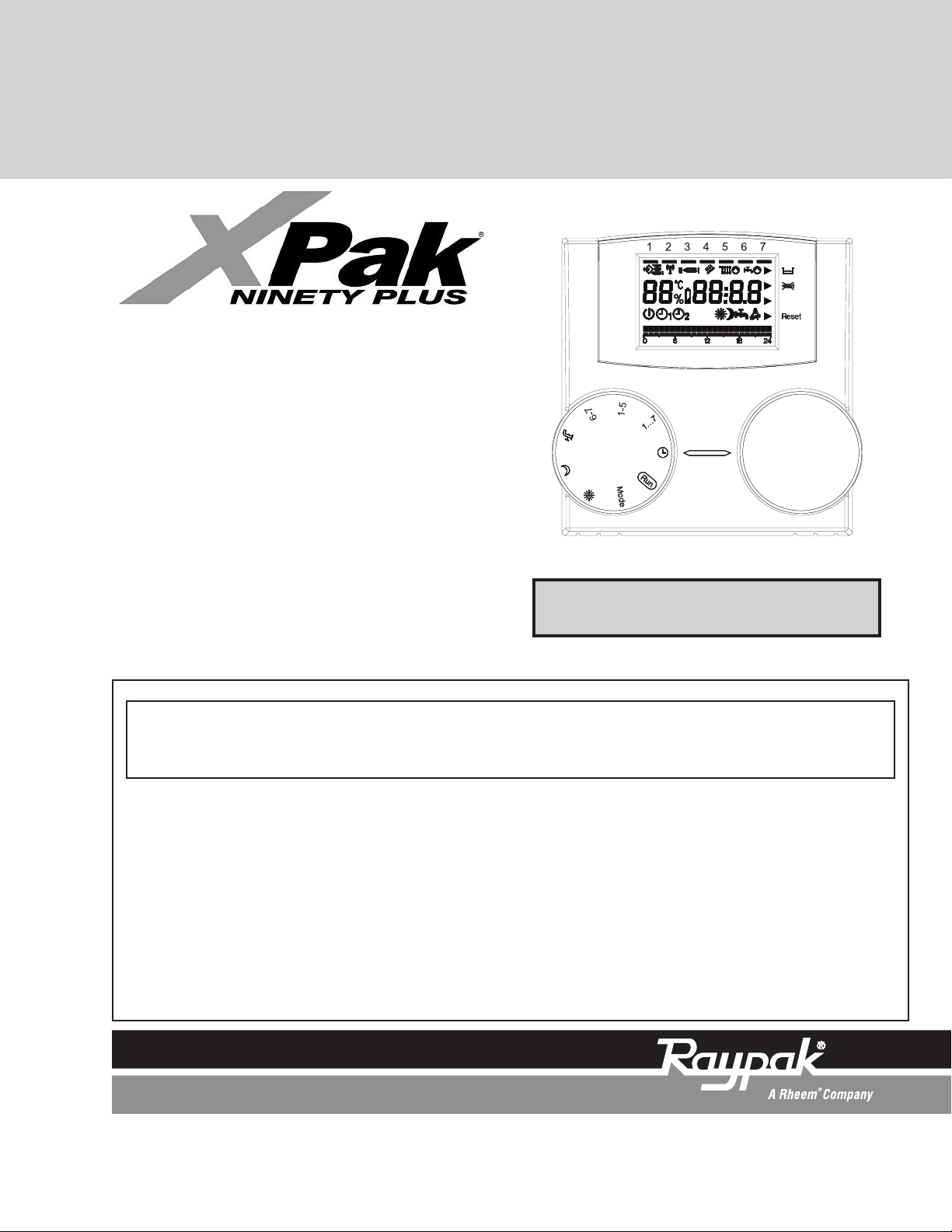
OPERATING INSTRUCTIONS
Remote
Control
Panel
For Models 85 & 120
REC08
FOR YOUR SAFETY: Do not store or use gasoline or other flammable vapors and
liquids or other combustible materials in the vicinity of this or any other appliance. To
do so may result in an explosion or fire.
WHAT TO DO IF YOU SMELL GAS:
• Do not try to light any appliance.
• Do not touch any electrical switch; do not use any phone in your building.
• Immediately call your gas supplier from a neighbor's phone. Follow the gas
supplier's instructions.
• If you cannot reach your gas supplier, call the fire department.
Installation and service must be performed by a qualified installer, service agency or
the gas supplier.
Effective: 01-26-10 Replaces: NEW P/N 208873 Rev. 1
Page 2

2
Page 3

TO USE THE REMOTE CONTROL PANEL CORRECTLY, CAREFULLY READ
THE CONTENTS OF THIS DOCUMENT.
WARNINGS:
1) The remote control must be installed where it can
be easily accessed for ambient temperature control
(generally in the living room).
2) To optimize legibility of the display, the control
panel must be positioned 5 feet from the floor, as
required by regulations.
3) The control panel is powered by low voltage
directly from the boiler.
4) The control panel must be kept away from heat
sources or drafts, as these can compromise the
accuracy of the ambient probe incorporated in the
panel.
5) Never open the panel, as it is maintenance-free.
6) Never press on the glass of the liquid crystal
display, as this may damage the glass and impair
viewing.
7) Only use a dry cloth to clean the display, as any
infiltration of liquids may damage the liquid crystals.
GLOSSARY OF TECHNICAL TERMS
• Heating water: This is the water which flows in the
comfort heat radiators after having been heated by
the boiler.
• Domestic hot water: This is the potable water
which flows to the fixtures in the home.
• Fault code: This is a code which appears on the
display to report any boiler or control panel operational problems.
• Initial configuration: This is the configuration of
the control panel after initial start-up or resetting.
• Display: This is the liquid crystal screen showing
all the symbols corresponding to the various functions.
• Freeze protection function: This function prevents low temperatures from freezing the water
flowing inside the pipes and damaging the heating
system. This function activates when the ambient
temperature falls below 40°F (5°C).
GENERAL INFORMATION
WHAT DOES THE REMOTE CONTROL
PANEL DO?
The remote control panel allows you to control the
temperature in your home and the operation of your
boiler without having to access the boiler directly. For
reasons of space, in fact, your boiler may be installed
outside the living space (e.g.: basements, garages,
external areas, etc.). The control panel, on the other
hand, is generally installed in the largest room of the
home, where control and adjustment operations can
be performed with ease.
OPERATING METHOD
The control panel allows more refined home heating
management, as you can decide how and when to
start the boiler. It also allows you to set the domestic
hot water temperature without having to access the
boiler panel. This manual sets out to explain each of
these operating methods and their connected functions.
• Control panel reset: This operation is performed
to reset the initial configuration of the control panel
by deleting any user program apart from the system clock.
• Summer mode: Set the control panel to this mode
when the heating system is not required (e.g.:
spring, summer). The boiler only delivers domestic
hot water (when piped to domestic hot water).
• Automatic heating and continuous heating
mode: Set the control panel to this mode when
heating is required (e.g.: autumn, winter). The boiler delivers both domestic hot water and heating
water.
• Comfort temperature: This temperature optimizes
heating in the home.
• Setback temperature: This temperature is used
when the home is uninhabited, or during the night.
• Ambient temperature: This is the temperature
measured in the room in which the remote control
panel is installed.
3
Page 4
• Outdoor temperature: This is the temperature
easured outside the house by the external sensor
m
(if installed) connected to the boiler.
• Outdoor reset curve: This is the relationship
between the external temperature and the temperature of the heating water. If the outdoor probe is
installed with the boiler, the temperature of the
heating water is automatically adjusted according
to the changes in outdoor temperature in order to
maintain a constant temperature in the home. The
outdoor reset curve is chosen by the installer
according to the geographical location and system
NOTE:
• The ambient temperature display ranges from
32°F to 210°F (0°C to 99°C).
• The outdoor temperature display ranges from
-38°F to 102°F (-39°C to 39°C).
• Temperatures outside these ranges are displayed
with three dashes “---”.
• Temperatures below 100° (°F or °C) will be displayed in tenths of a degree (XX.X).
• Temperatures of 100° or higher (°F) will be displayed in whole degrees (XXX°F)
OTE: Refer to Figure 35 on page 36 of the XPak
N
Installation and Operating Instructions for connections from this Remote Control Panel to the XPak
boiler.
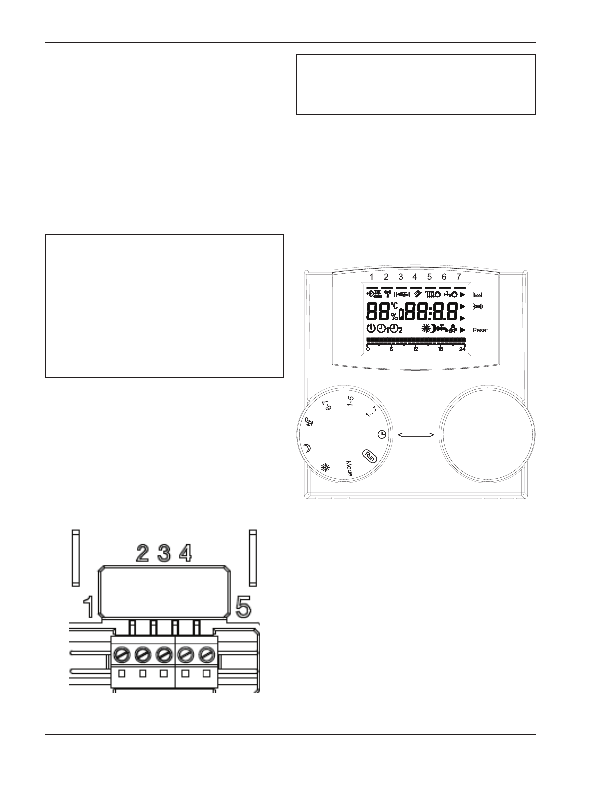
SWITCHES
The remote control unit features two directly accessible ENCODER knobs. The left-hand knob (SELECT)
is used to select the operating mode. Turn to “RUN”
for normal operation. The right-hand knob (EDIT) is
used to modify the selected value.
USING THE CONTROL PANEL
ELECTRICAL CONNECTIONS
1 = OT Bus
2 = OT Bus
3 = Phone switch
4 = Phone switch
5 = Not used
Fig 2: Switches
Fig. 1: Electrical connections
4
Page 5

Boiler status
The boiler status and communication
status are displayed
OT+ communication correct
Flame present in boiler
Current heating demand in boiler
Current domestic hot water
demand in boiler
Current heating program
Control panel operating mode
The current operating status of the control panel is
shown on this row of the display:
Standby / OFF
Automatic operation Heating according to
program 1
Automatic operation Heating according to
program 2
Continual heating at comfort temperature
Continual heating at setback temperature
Summer mode
System information
Some system information is shown on the central line of the display.
The ambient temperature and time are normally displayed 70 °F 16:32
If the holiday function is enabled, the time remaining in days
.deyalpsidsi
In case of a fault, ambient temperature and fault code are displayed. 70 °F E001
Turn the right-hand knob (EDIT) to view:
- Outdoor temperature (only if the outdoor air sensor is installed
in the )reliob
- Boiler supply temperature
°F 128.7
- Boiler supply temperature setpoint
(calculated by the remote control unit)
°F 128.7
- Domestic hot water temperature at boiler
°F 116.0
The day of the week is
indicated by the corresponding
segment lighting up on the
first row of the display.
Day of the week
Shows the current heating program.
AF °F 60.3
HO 05
Radio communication function
(not used on REC08)
Solar panel thermostatic control
Status during Service Technician repair
(not used on REC08)
(not used on REC08)
-- --
- Battery charge status (not used on REC08)
Fig. 3: Run Mode
5
Page 6

“”
“”
PL
HO
“”
RUN MODE
With the left-hand knob (SELECT) turned to “RUN,”
the control panel displays the information required to
check the status of the control panel and boiler. The
information is displayed in Fig. 3 on page 5.
Technical level
Setting of parameters 1-17.
oliday setting
H
CONTROL PANEL OPERATING MODE
SETTINGS
Turn the left-hand knob (SELECT) to “MODE” and
turn the right-hand knob (EDIT) to set one of the following
operating modes:
Standby / OFF
Heating and hot water are disabled. Only the freeze
protection function remains enabled.
Automatic operation - heating according to
program 1
Heating with program 1. Domestic hot water production enabled.
Automatic operation - heating according to
program 2
Heating with program 2. Domestic hot water production enabled.
Continual heating in comfort mode (manual)
24-hour heating at comfort temperature. Domestic
hot water production enabled.
Continual heating in setback mode (manual)
24-hour heating at setback temperature. Domestic
hot water production enabled.
Heating and hot water are disabled. Only the
freeze protection function remains enabled.
After setting the parameters, turn the SELECT knob
back to “RUN.”
Setting the comfort temperature
Turn the left-hand knob (SELECT) to
and turn the EDIT knob to set the required temperature from 40°F to 104°F (5°C to 40°C). After setting
the parameter, turn the SELECT knob back to “RUN.”
Setting the night setback temperature
Turn the left-hand knob (SELECT) to
and turn the EDIT knob to set the required temperature from 40°F to 104°F (5°C to 40°C). After setting
the parameter, turn the SELECT knob back to “RUN.”
Setting the domestic hot water temperature
Turn the left-hand knob (SELECT) to and
turn the EDIT knob to set the required temperature
from 95°F to 122°F (35°C to 50°C). After setting the
parameter, turn the SELECT knob back to “RUN.”
Setting the day of the week
Turn the left-hand knob (SELECT) to “1….7” and turn
the EDIT knob to set the required day of the week.
After setting the parameter, turn the SELECT knob
back to “RUN.”
Summer mode
No heating (only freeze protection). Domestic hot
water production enabled.
6
Page 7

Setting the time
“”
Turn the left-hand knob (SELECT) to
and turn the EDIT knob to set the current time. After
setting the parameter, turn the SELECT knob back to
“RUN.”
Setting the holiday program
Turn the SELECT knob to “MODE,” and then turn the
EDIT knob to “HO” and set the required number of
days holiday. Turn the SELECT knob back to “RUN.”
The function begins immediately and ends at midnight
on the last set day.
Heating program 2 is be used to modify parameters 1
(Monday) to 7 (Sunday). To set heating program 2,
enter the technical menu and select parameters 1 to 7
depending on the day being set. To do so, turn the
SELECT knob to “MODE” and then select “PL” with
the EDIT knob.
Select the required parameter by turning the SELECT
knob clockwise: 01 for Monday through 07 for Sunday.
Next to the heating program sign, the display shows
the current program in hours, the day or group of days
to which the programming refers, the programming
time and, the first hour block, which will be flashing. On
and off times are then set for both heating programs.
Turn the right-hand (EDIT) knob counter-clockwise to
set the heating phases at setback temperature. Turn
it clockwise to set the heating phases at comfort temperature. Every turn of the knob corresponds to a 15minute increase in time, and every movement of the
cursor corresponds to a 1-hour increase.
To exit heating program 1 settings, turn the SELECT
knob to “RUN.”
Fig. 4: Setting the holiday program
(Example shown indicates a 5-day holiday.)
Setting the heating program
The remote control unit can be used to set two heating
programs.
Heating program 1 is used to modify two blocks of
days independently: Monday-Friday and SaturdaySunday.
To set heating program 1, turn the SELECT knob to “6
– 7” in order to modify Saturday and Sunday settings
or to “1 – 5” in order to modify those of the rest of the
week.
To exit heating program 2 settings, after programming
the days of the week, turn the SELECT knob clockwise
to “PL,” turn the EDIT knob counter-clockwise until it
reaches the required operating mode (see the dedicated section). Then turn the SELECT knob to “RUN.”
Programming takes place throughout the 24 hours.
After 23:45, the hour block switches to 0:00.
Fig. 5: Setting the heating program
7
Page 8

Fault display
Reset blocks in case of boiler error
Faults are displayed with EXXX, where XXX is the
efault code generated by either the remote control
d
unit or the boiler. The code is displayed instead of the
time on the information line. The signal is fixed if the
alarm does not require a RESET while it flashes if it
requires the RESET procedure. Table A shows the
fault codes generated by the thermostat timer.
Fig. 6: Fault display
Some boiler alarms can be directly reset from the
emote control unit. In these cases, in addition to the
r
code flashing on the display, a triangle lights up next to
the RESET message on the right-hand side of the display (see Fig. 6). At this point, the RESET function can
be activated. Turn the EDIT knob clockwise. A
RESET command equivalent to pressing the button on
the boiler is generated and the release command is
sent to the boiler. The arrow disappears after the
RESET command has been given.
Error # Description
No communication with boiler. Data
E 201
E 81
E 80 Fault in the ambient temperature sensor.
Table A: Fault codes generated by the thermostat timer
For definitions of the alarms generated by the boiler,
please consult the XPak Installation and Operating
Instructions.
transmission to the boiler must be
checked.
EEPROM Error
This code means the memory of the termostat timer has been altered (e.g. via
EMV). Following the error, the default
data is loaded.
All the set values must be checked.
Fig. 7: Reset blocks in case of boiler error
Technical menu
To enter the technical menu, turn the SELECT knob
to “MODE,” turn the EDIT knob to “PL” and then
select the required parameter using the SELECT
knob.
Turn the EDIT knob to set the required value.
To exit the technical level, select the forward/back
parameter, “PL,” using the SELECT button and then
turn the EDIT knob.
Both heating program 2 and some installer parameters can be set in the technical menu.
To set the heating program, parameters 01-07, consult the above section
8
Page 9

Setting the heating program
Parameters 08 through 17 refer to ambient tempera-
ure adjustment and boiler operation.
t
WARNING: Changing the values of parameters
08 through 17 may compromise the normal operation
of the boiler. These parameters should be changed by
qualified technicians only.
08 Maximum heating temperature
Maximum delivery temperature of boiler in the
heating mode.
09 Minimum heating temperature
Minimum temperature of boiler in the heating
mode. If the outdoor air sensor is not fitted and
parameter 11, internal sensor influence, equals
zero, this parameter is used as a set point for the
temperature of the heating water.
10 Heat adjustment curve for heating water
This is only enabled if an outdoor air sensor is
connected. Relation curve of the outdoor air sensor in the algorithm used to calculate delivery temperature adjustment.
11 Internal sensor influence
Importance of the ambient temperature sensor in
the algorithm used to calculate delivery temperature adjustment.
12 Not used
13 Ambient sensor offset
Temperature offset of the measured internal sensor; this is used to adapt the value to the place of
installation.
14 Loading default parameters
Set this parameter to 1 to load the default configuration of the parameters. The day and time are
not modified.
15 Supplementary heat adjustment constant
Offset parameter in the algorithm used to calculate
delivery temperature adjustment.
16 Software version
This displays the code of the software implemented on the remote control unit.
17 °C/°F selection
This parameter selects whether to view temperatures in °F (Fahrenheit) or °C (Celsius).
9
Page 10

Maximum Delivery Temperature (°C/°F)
Outdoor Air Temperature (°C/°F)
20 16 12 8 4 0 -4 -8 -12 -16 °C
68 61 54 46 39 32 25 18 10 3 °F
68
104
140
176
212
°F °C
Fig. 8: Heat Adjustment Curves for heating water
10
Page 11

CODE CAUSE ALARM TYPE ACTION
AL10 Ignition failure/not flame sensed, Final Reset, check appliance operation
condense sensor activated
AL 20 Limit thermostat fault, blocked flue switch,
flue thermostat
Final Reset, check appliance operation
AL21 External device fault (UHT/CPA) Final Reset, check appliance
A
L26 Return temperature too high Final Reset, check pump, ensure there is sufficient
flow sensor temperature). Circulation around
heating circuit/s
AL2 Temperature differential inverted Final Reset, check pump, ensure there is sufficient
(return sensor temperature higher than circulation around heating circuit/s thermistors
flowsensor temperature)
AL29 Flue sensor over temperature lock out Final Reset check appliance operation
AL34 Fan blower signal fault Final Reset check appliance operation, check fan
AL40 Insufficient system water pressure Final Check/refill system pressure, reset, check
appliance operation
AL41 Insufficient system water pressure Temporary Check/refill system pressure, check appliance
operation
AL52 Internal fault Final Reset, check boiler operation
AL55 Jumper tag fault Final Check jumper tag configuration
AL60 Jumper tag fault Temporary Check jumper tag configuration
AL71 Primary (flow) sensor fault Temporary Check primary thermistor, check wiring
AL73 Return sensor fault Temporary Check return thermistor, check /wiring
AL74 Variation on temperature of primary Final Reset, check boiler operation, check
and/or return too high pump, ensure there is
sufficient circulation around heating circuit/s
AL79
Flow temperature too high, or
Final
Reset, check appliance operation, check
temperature differential between thermistors
primary and return too high
AL91
The main heat exchanger need to be
Advice
Call Raypak technical service
cleaned
XPak Fault Codes
Table B: XPak Fault Codes
11
Page 12

Raypak, Inc., 2151 Eastman Avenue, Oxnard, CA 93030 (805) 278-5300 Fax (805) 278-5468
Litho in U.S.A.
12
 Loading...