

Page 1
INSTALLATION & OPERATING
INSTRUCTIONS
Heat Pump
Pool & Spa
Heater
Professional
Series
9350HC and
9353HC
FOR YOUR SAFETY: Do not store or use gasoline or other flammable vapors and
liquids or other combustible materials in the vicinity of this or any other appliance. To
do so may result in an explosion or fire.
NOTE: The instructions in this manual are for the use of qualified individuals specially trained and experienced
in the installation and maintenance of this type of equipment and related system components. Installation and
service personnel are required by some states to be licensed. Persons not qualified shall not attempt to install,
service, or maintain this equipment.
This manual should be maintained in legible condition and kept adjacent to the heat pump pool heater or in a
safe place for future use.
Catalog No. 6000.58A Effective: 09-10-15 Replaces: 03-01-15 P/N 241571 Rev. 2
92-103778-11-02
Page 2
ATTENTION: Please Take This Opportunity to Quickly Register Your Unit!!
While your unit is being installed by your professional and licensed installer of choice, Please Take This
Opportunity to Quickly Register Your Unit!! With the necessary information in hand, Registering your new Heat
Pump Pool Heater only takes a few moments and is the only way to assure any verifiable warranty procedures
uring the span of your unit's period of protection.
d
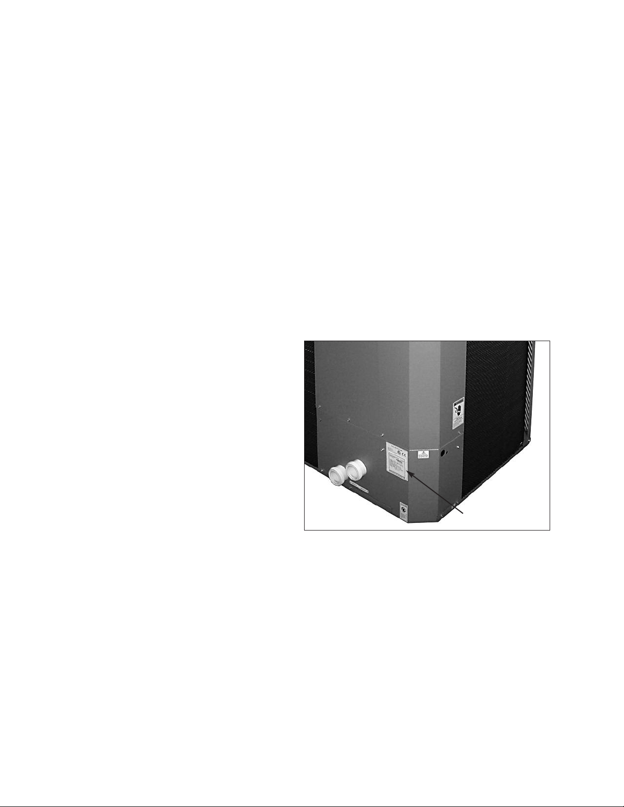
Using the diagram at the bottom of the page (Fig. i) please locate and record your model and serial number.
Once you have done this, please make sure you also have the following information on hand:
• Name, phone number, and email address of homeowner
• physical address of where the unit is installed; please include any
'subdivision' or similar information
• any service challenges present at the house/neighborhood: gated
community, locked access at house, guard dog, etc.
• date of installation of the new unit
• name and phone number of the professional and licensed entity that
performed the installation for you
With all of the above information in hand, please feel
free to call us at 800.260.2758 and ask to register your
brand new heat pump.
You will be given a Warranty Registration Confirmation
number which you should notate and keep in one location along with your Installation & Owner's Manual, a
copy of your warranty (provided with your manual) and
the above information.
This would also be a good time to review both the
manual and the warranty so that you are aware of how
to correctly operate your new equipment as well as
how to keep from voiding any aspects of your warranty.
During the life of your unit, please feel free to use the
above phone number, or the one conveniently located
right on the unit, to contact us with any questions you
may have about operation, warranty, and/or service.
Thank You Very Much Choosing us to Satisfy Your
Pool Heating needs!!
NAMEPLATE
Fig. i: Model and Serial Number Location
Rev. 2 reflects the following:
Changes to: Wiring diagrams on pages 32-33
Additions: None.
Deletions: None.
2
Page 3
Water Chemistry
(Corrosive water voids all warranties)
For your health and the protection of your pool equipment, it is essential that your water be chemically
balanced. The following levels must be used as a guide for balanced water.
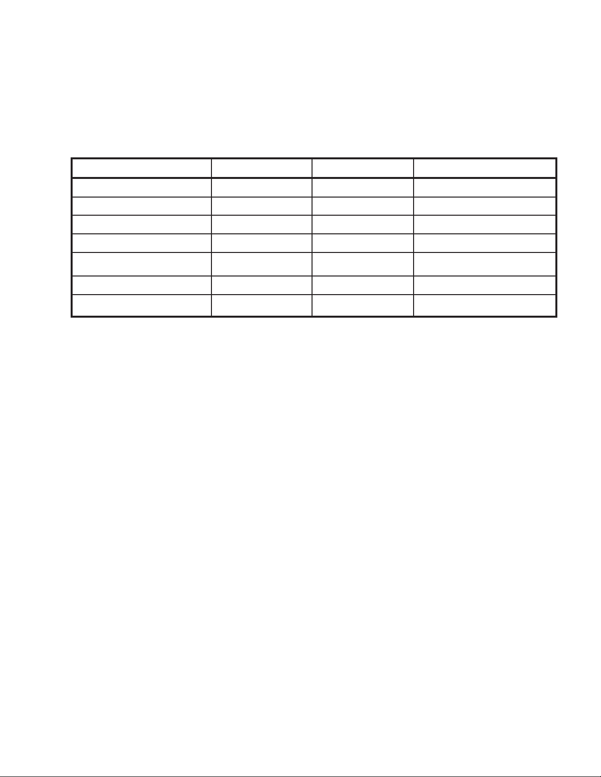
Recommended Level(s) Fiberglass Pools Fiberglass Spas Other Pool & Spa Types
Water Temp. (Deg. F) 68 to 88 89 to 104 68 to 104
pH 7.3 to 7.4 7.3 to 7.4 7.6 to 7.8
Total Alkalinity (PPM) 120 to 150 120 to 150 80 to 120
Calcium Hardness (PPM) 200 to 300 150 to 200 200 to 400
Salt (PPM)
Free Chlorine (PPM)* 2 to 3 2 to 3 2 to 3
Total Dissolved Solids (PPM)
*Free Chlorine MUST NOT EXCEED 5 PPM!
** In salt water chlorinated pools, the total TDS can be as high as 6000ppm.
• Occasional chemical shock dosing of the pool or spa water should not damage the heater providing
the water is balanced. However, it is highly recommended that the heat pump pool heater is isolated via shut off valves before any aggressive chemical treatment.
• Automatic chemical dosing devices and salt chlorinators are usually more efficient in heated water.
Unless controlled, they can lead to excessive chlorine level which can damage your heater.
• Further advice should be obtained from your pool or spa builder, accredited pool shop, or chemical
supplier for the correct levels for your water.
4500 MAXIMUM 4500 MAXIMUM 4500 MAXIMUM
3000 MAXIMUM** 3000 MAXIMUM** 3000 MAXIMUM**
3
Page 4

CONTENTS
Water Chemistry 3
Warnings 5
Pay Attention to These Terms 5
Introduction 6
Installation Considerations 6
Electrical Connections 7
Water Connections 9
Pressure Drop 9
HPPH Control Display 10
User Modes 11
HPPH Control Menus 11
USER MENU — HEAT/COOL Model
Type Selection 12
INSTALLER/SERVICE MENU —
HEAT/COOL Configuration 14
Control Settings 18
Set Current Time 18
C/F Display 18
Spa Max Temp 18
Pool Max Temp 18
Pump Periods 18
Temperature Control 18
Additional Features 18
Pump Control 18
Low Ambient (Outside) Lockout 18
Control Lock Box Mode 19
AUX Mode 19
Remote Pool Operation 19
Pool Auto Mode 19
Fault History
Run Hours/Cycles 19
Compressor Start Delay 20
Minimum Run Time 20
Defrost Operation 20
3-Way Valve Control 20
Battery Back-up 20
High Water Temperature Limit 20
High Pressure Switch Lockout 20
Low Pressure Switch Lockout 20
Water Flow Switch 21
Controls 21
Digital Controls Operating
Instructions 21
To Increase or Decrease the Desired Water
Temperature (Pool or Spa Mode) 22
Select Temperature in °C or °F 22
Heat/Cool Operation 22
System Start-Up 22
Seasonal Start-Up or
Annual Check 22
Summer Shutdown 22
Freeze Protection 23
System Drain-Down 23
Continuous Pump Operation 23
Maintenance 23
Air Coil Cleaning 23
Cabinet Care (optional) 23
Unplug Condensation Drain Holes 23
Troubleshooting 24
Service Call Verification 27
Power Supply 27
Water Flow 27
Time Clock Adjustment 27
Set Factory Defaults 27
Plumbing Diagrams 28
Wiring Diagram — 208V/230V
Single-Phase — Digital Models 32
Wiring Diagram — 208V/230V
Three-Phase — Digital Models 33
Installing a Remote Control
Device 34
Heater 2-Wire Controllers (Heat Only) 34
3-Wire Controllers 34
2-Wire Controllers For “Chill” Mode Heat/Cool Models Only 34
4
Page 5
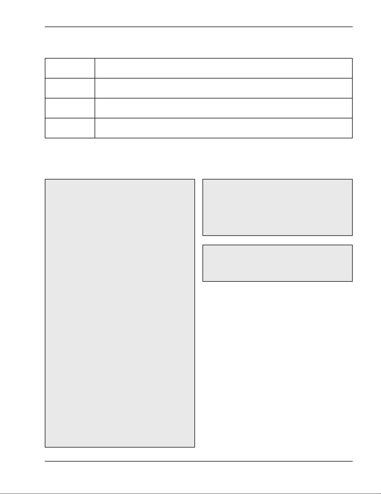
Warnings — Pay Attention to These Terms
ndicates the presence of immediate hazards which will cause severe personal injury, death
DANGER:
I
or substantial property damage if ignored.
WARNING:
CAUTION:
NOTE:
This manual, as well as the pool/spa heat pump pool heater itself, contains ANSI-approved product safety signs
and labels. Please read these signs and labels, as they convey important safety information about hazards that
may be potentially present in and around the heat pump pool heater.
CAUTION: Elevated water temperature can be
hazardous. The U.S. Consumer Product Safety
Commission has these guidelines:
1. Spa water temperatures should never exceed
104°F (40°C). A temperature of 100°F (38°C) is
considered safe for a healthy adult. Special caution is suggested for young children.
2. Drinking of alcoholic beverages before or during
spa or hot tub use can cause drowsiness which
could lead to unconsciousness and subsequently
result in drowning.
Indicates the presence of hazards or unsafe practices which could cause severe personal
injury, death or substantial property damage if ignored.
Indicates the presence of hazards or unsafe practices which could cause minor personal
injury or product or property damage if ignored.
Indicates special instructions on installation, operation, or maintenance which are important
but not related to personal injury hazards.
CAUTION: Improper chemical content in a swimming pool or spa can damage the heat pump pool
heater. DO NOT add pool chemicals to the skimmer.
This will damage the heat pump pool heater and
could void the heat pump pool heater warranty.
ALWAYS follow the product manufacturer’s directions when adding any chemicals to your pool.
WARNING: These heat pump pool heaters are
charged with R-410A refrigerant. Ensure that all
service work is done with gauges and equipment
suitable for R-410A.
3. Pregnant Women Beware! Soaking in water over
102°F (39°C) can cause fetal damage during the
first three months of pregnancy resulting in the
birth of a brain-damaged or deformed child.
Pregnant women should stick to the 100°F (38°C)
maximum rule.
4. Before entering the spa or hot tub, users should
check the water temperature with an accurate
thermometer; spa or hot tub thermostats may err
in regulating water temperatures by as much as
4°F (2.2°C).
5. Persons with a medical history of heart disease,
circulatory problems, diabetes, or blood pressure
problems should obtain a physician's advice
before using pools or hot tubs.
6. Persons taking medications which induce drowsiness, such as tranquilizers, antihistamines, or
anticoagulants, should not use spas or hot tubs.
5
Page 6

Introduction
Installation Considerations
WARNING: This pool/spa heat pump pool heater is
an electromechanical machine that incorporates a
ressurized refrigerant gas in a sealed system.
p
ONLY trained and qualified service personnel are
uthorized to install or service this equipment.
a
Without proper training and knowledge of such
equipment, any attempt to install or service the unit
could result in serious injury or even death.
This manual contains important information on the
use, maintenance and troubleshooting of your new
heat pump pool heater. This unit must be properly
installed, maintained and operated for optimal performance.
This heat pump pool heater is an extremely efficient,
economical machine designed specifically for swimming pool heating. It is similar in design and operation
to a typical residential air conditioning system. The unit
employs a hermetic motor/compressor operating in a
refrigeration cycle to extract heat from ambient air and
deliver it to the circulating pool water.
As with all heat pump pool heaters, compared to other
types of heaters such as gas or oil-fired, this heat
pump pool heater has lower heating capacity on a
BTUH/hr basis. As a result, it will be required to operate longer to accomplish the desired results. It may, at
certain times, operate as much as 24 hours per day.
However, this should not be of concern to the owner,
because the unit is designed to operate continuously.
Even though it may operate continuously for many
hours, it will still heat the pool with greater economy
than other types of fossil fuel heaters.
Place a cover or blanket over the pool at night and
other non-use periods. This will keep evaporation, the
cause of main heat loss, to a minimum, and will greatly reduce pool heating costs. During warmer weather,
the cover may be required only at night.
WARNING: Do not install the unit within 3 ft of
ossil fuel burning heaters. Air intake along the
f
sides of this heat pump pool heater could disturb
the combustion process of the unit, and could
cause damage or personal injury.
• Mount the unit on a level, sturdy base, preferably
a concrete slab or blocks. The size of the base
should be at least 3 ft by 3 ft.
• You must install the 4 black rubber sound isolation pads (each 2 inches square) that ship with
the unit. The pads are shipped in a bag with the
unions, gaskets and the I&O manual. Install pads
under the 4 corners of the unit to reduce vibration and sound transmission to the base.
CAUTION: The unit’s supporting base must be high
enough to keep it completely free of standing water
at all times.
Situate the heat pump pool heater carefully to minimize installation costs while providing maximum
efficiency of operation, and to allow adequate service
access, as follows:
• For unrestricted air intake and service access,
position each side of the unit at least 1 ft (30 cm)
from walls, pipes and other obstructions.
WARNING: This unit is designed for outdoor installation; DO NOT install it in an enclosed area such as
a shed or garage.
• Recirculation of cold discharge air back into the
evaporator coil will greatly reduce the unit’s heating capacity and efficiency.
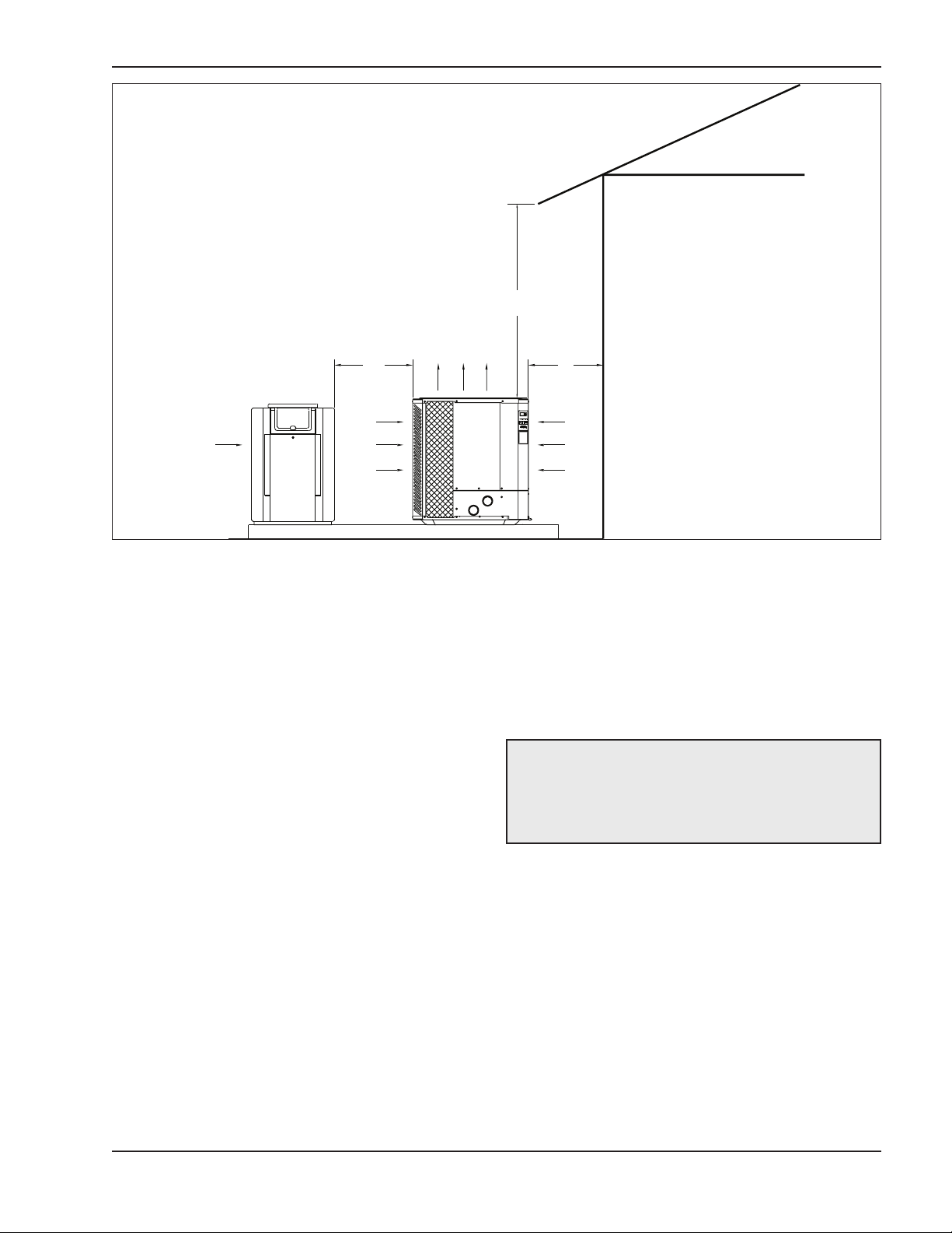
• This unit features an ‘up-flow’ discharge for quiet
operation. Air is pulled up through the evaporator
coil and discharged through the top grill. Allow at
least 5 ft (1.5 m) clearance above the unit for unrestricted air discharge. DO NOT install the unit
under a porch or deck. Refer to Fig. 1.
• To minimize water piping, locate the unit as close
as possible to the existing pool pump and filter.
6
Page 7
G
AS
HEATER
AIR
FLOW
IN
AIR
FLOW
IN
AIR FLOW OUT
3 FT
M
IN
12”
MIN
6
0”
MIN
Fig. 1: Installation Clearances
• Irrigation water should be directed away from the
heat pump pool heater-water spray can damage
the heat pump pool heater.
• Rain water run offs- the heat pump pool heater
can withstand normal rain. Install rain gutters to
prevent direct steams of rain water to the heat
pump pool heater.
• It is important to keep the area next to the heat
pump pool heater clear of shrubs, bushes and
chemicals containers. They could prevent air from
circulating fully through the heat pump pool heater,
and will affect the operation of the heat pump pool
heater or damage the heat pump pool heater.
• When installed in areas where freezing temperatures can be encountered, drain the water circuit
to prevent possible freeze-up damage.
• For high wind installation requirements, refer to
the diagram on page 8.
Electrical Connections
Refer to the unit rating plate below the control panel for
precise power requirements for your unit, and for
ampacity and over-current protection requirements.
All wiring must be in accordance with the National
Electrical Code, NFPA No. 70, latest edition, and all
applicable state and local codes. Wiring diagrams are
located on pages 32 through 33.
• Locate the equipment disconnect means within 3
feet of the heater’s electrical enclosure, or as
close to the heater as possible. Always satisfy
applicable codes and standards.
NOTE: Refer to the National Electrical Code, Article
680, for general requirements for swimming pools
and equipment, and to Article 440 for special considerations necessary for circuits supplying hermetic
refrigeration motor/compressors.
• In sizing power wiring, be especially aware of upsizing requirements necessary due to wiring
distances. Always satisfy applicable codes and
standards.
• Electrical installation should be done by a licensed
electrician only.
This unit is pre-wired to work with external control systems, heat-on-demand options and other external time
clock overrides. Refer to the external control system’s
instructions, and page 19 of this manual, for installation information.
7
Page 8
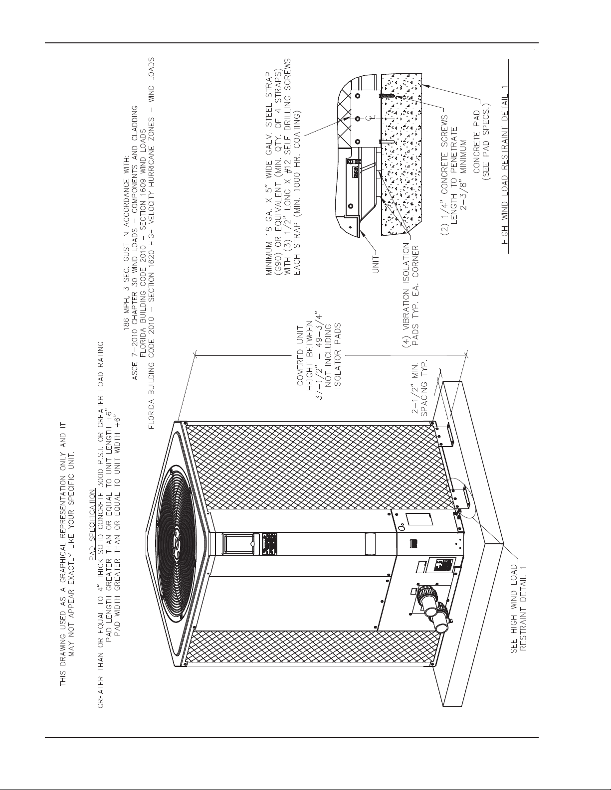
Fig. 2: Hurricane Tie Down Instructions
8
Page 9
Model No. VAC in - Phase - Hz
9350HC 208/230 - 1 - 60 42.0 50 60
9353HC 208/230 - 3 - 60 34.0 40 50
Table A: Typical System Electrical Power Requirements
Minimum Circuit
Ampacity (A)
Breaker Size (A)
IN
M
M
AX
Water Connections
CAUTION: The heat pump pool heater inlet and
outlet connections are NOT interchangeable. They
must be connected as instructed below.
1. Connect the heat pump pool heater in the return
water line between the filter and the pool/spa. See
the Plumbing Diagrams beginning on page 28.
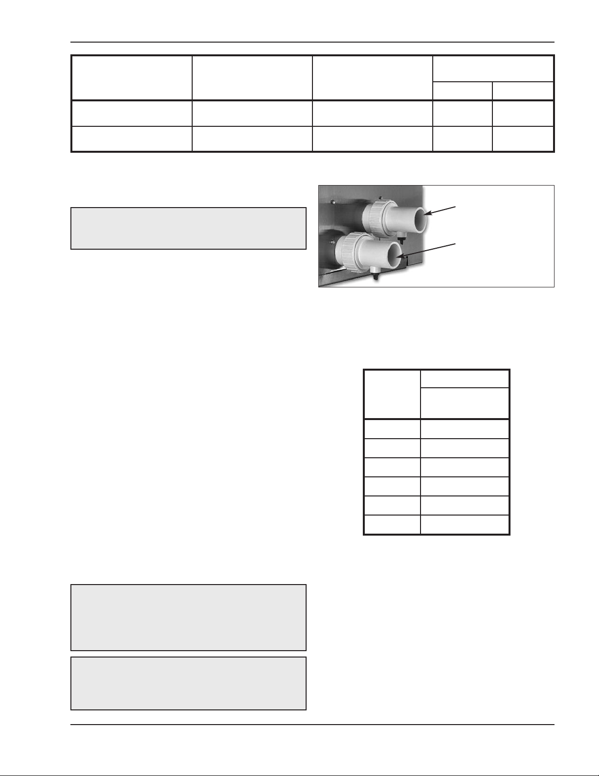
2. Connect the filter outlet to the fitting marked
WATER IN at the bottom front of the unit.
3. Connect the fitting marked WATER OUT to the
return piping to the pool/spa. Unit inlet/outlet connection fittings are 2-inch PVC unions.
Water connections from the unit to the main return
line can be PVC pipe or flexible pipe approved for
the purpose and, in either case, should be at least
equal in size to the main pool/spa circulation piping.
4. In cold weather (freeze zone) areas, shutoff valves
(ball or gate type) must be installed at the unit inlet
and outlet to facilitate service and cold weather
drain-down.
WATER OUT
WATER IN
Fig. 3: Water Connections
Pressure Drop
For system pressure drop information, refer to Table B
below.
Flow
(gpm)
30 9
40 9
50 10
60 11
70 12
Pressure Drop
9350HC/
9353HC
5. Operate the pump and check the system for leaks.
6. Drain plugs are located on each union fitting as
shown in Fig. 3 for draining the system during winterizing.
NOTE: While it is possible to mount the upper union
with the drain plug vertically, Raypak has determined
that installing both unions with the drain plugs facing
down as shown in Fig. 3 provides for the best draining of the system.
CAUTION: When the drain plugs are removed for
draining the system, ensure that they are stored in a
safe place for re-installation when needed to restart
the system.
80 13
Note: Multiply the pressure drop in psi by 2.3067 to yield the pressure drop in Ft. H2O Head (TDH).
Table B: Pressure Drop Across Heat Pump Pool Heater
9
Page 10
WARNING: Install a check valve and/or a Hartford
loop AFTER the heat pump pool heater and
BEFORE any chlorinating devices. Install any auto-
atic chemical feeders AFTER the heat pump pool
m
heater. Improper installation of any type of auto-
matic chemical feeders can result in serious
damage to, or premature failure of, the heat
ump pool heater and will void the heat pump
p
pool heater warranty.
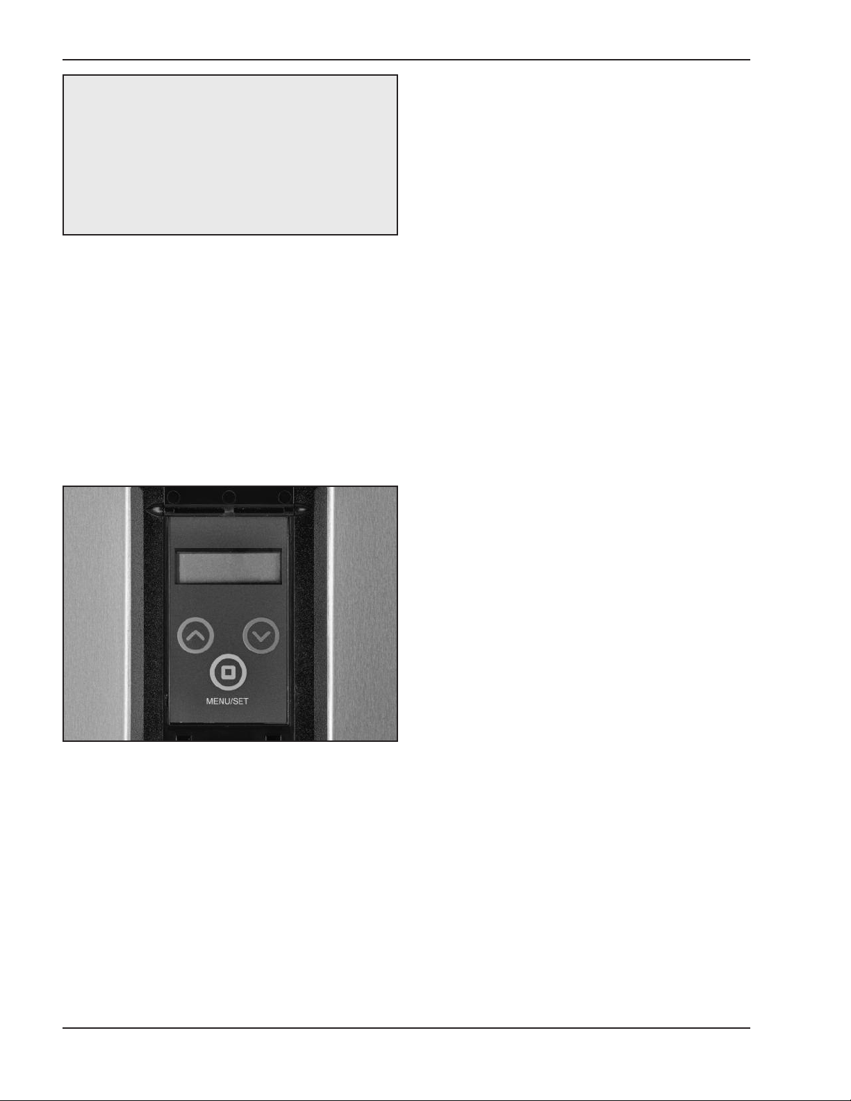
HPPH Control Display
The HPPH display is viewable from outside of the
heater. All operation and settings of the HPPH control
are accomplished through the use of the 3 buttons of
the user interface. These buttons are labeled as follows:
• MENU/SET – Scroll through available menus
and set changed values (MENU)
• UP – Increase values in the Adjust menu
• DOWN – Decrease values in the Adjust menu
and OFF. The cooling setpoint can be adjusted in the
range of 50F to the Cooling Deadband value below the
Heating setpoint. This allows use in Plunge Pools.
Adjust the cooling setpoint accordingly.
The control board is equipped with a red status LED
n the back of the board which flashes at a “heartbeat”
o
of 2Hz while operating normally. The control board is
also equipped with a green LED (next to the communications jack) on the back of the board which will
flicker to indicate active communications when connected to another system.
Upon initial application of power, the HPPH control
briefly sets all segments on the LCD at power-up. On
a normal power-up, the control displays the current
software revision and the model type configuration
(HEAT ONLY, POWER DEFROST or HEAT/COOL) on
the LCD for 2 seconds and then resumes the user
selected mode it was in before power was interrupted.
The configuration for these units should be
HEAT/COOL.
Setpoints are read from non-volatile memory. If the
self diagnostic check indicates corrupted values,
“EEPROM Fault” is displayed on the LCD and operation is prohibited until setpoints are manually set.
Fig. 4: HPPH Control Display
The display uses a 2-line, 16-character backlit Liquid
Crystal Display (LCD) as the method for supplying
information. The backlight is normally off. The backlight is on for 15 minutes after Power-Up and for 15
minutes after any button press. Use the LCD to setup
and monitor the operation of your heater.
If the membrane switch remains inactive for 180 seconds (3 minutes), the screen will revert to the current
view.
On HEAT/COOL models, the options available by
pressing the MENU/SET (MENU) button are POOL
HEAT, POOL COOL, POOL AUTO, SPA, TIMED SPA
If unit type has not been set (like during the replacement of the HPPH control), the control prompts the
user to set the model type (HEAT ONLY, POWER
DEFROST, or HEAT/COOL) before any device operation is enabled. Installation in these models requires a
model type of HEAT/COOL to be selected.
Upon initial installation, there are several items that
must be defined and programmed depending on the
configuration and accessories intended to be controlled by the HPPH control. These include: (1) 3-way
valve control (Yes or No), (2) Pump control (Yes or No
and then what type of control – 4-speed control or variable speed control), and (3) Auxiliary control (Yes or
No and then what type – External Heat, Auxiliary
Output or Remote Output).
Once these choices are made, then additional information relating to the establishing of pump periods,
pump speeds during each period and Return/Suction
Valve positions during each period must be determined and set in the control.
The options for the control can be very simple or very
detailed, depending upon each installation desires.
Once programming is completed, the control is ready
for operation.
10
Page 11

The user may select one of several operating modes
since these units are HEAT/COOL models. Each
mode is selected by pressing the MENU button to
cycle between the modes. Each press of the MENU
button selects the next mode. There is no automatic
increment from continually pressing the MENU button.
n fact, continually pressing the MENU button (for 3+
I
seconds) will move the user into the USER Menu.
temperature and the current operating state
“Heating” for example. Pressing the MENU button
will change the display to show the time remaining
n the timer. Press the MENU button again to go
o
back to the current status.
OTE: Setpoints are not adjustable while in the
N
OFF mode or if the Control Lock Box mode is active.
USER MODES
For HEAT/COOL models, the mode selections are:
OFF – POOL HEAT – POOL COOL – POOL AUTO
– SPA – TIMED SPA.
On HEAT/COOL models, there are additional operational modes available as noted below:
1. When POOL HEAT mode is selected, each press
of the UP or DOWN buttons will increase /
decrease the pool heating setpoint temperature.
Holding the UP or DOWN buttons down will speed
up the change of the temperature values.
2. When POOL COOL mode is selected, each press
of the UP or DOWN buttons will increase /
decrease the pool cooling setpoint temperature.
Holding the UP or DOWN buttons down will speed
up the change of the temperature values.
3. When POOL AUTO mode is selected, each press
of the UP or DOWN buttons will increase /
decrease the pool setpoint temperature. Holding
the UP or DOWN buttons down will speed up the
change of the temperature values.
4. When SPA mode is selected, each press of the UP
or DOWN buttons will increase / decrease the spa
setpoint temperature. Holding the UP or DOWN
buttons down will speed up the change of the temperature values.
5. When TIMED SPA mode is selected, the display
will read “Up or Dn to Set”. This tells the user to
press the UP or DOWN buttons to set the desired
timer for timed SPA heating operation. Pressing
the UP button will increase the timer in 15 minute
increments (up to a total of 6 hours). Pressing the
DOWN button will decrease the timer by 15 minute
increments. The timer will start and the unit will
begin heating as necessary to maintain the Spa
setpoint temperature for this duration. At the end of
the timed period, the unit will automatically go to
the last operational state (Pool Heat, Pool Cool,
Pool Auto, or OFF). Once the unit turns on, the
display will toggle between the current Spa water
The control saves the setpoint changes in non-volatile
memory and begins using them for heat demand
decsions after both the UP and DOWN buttons have
been released for 2+ seconds.
REMOTE Mode is accessed by pressing and holding
the UP and DOWN buttons simultaneously for 3 seconds. When exiting the REMOTE mode, the control
always selects the OFF Mode.
If the UP, DOWN or MENU buttons are pressed while
in REMOTE mode, the display will read “Exit Remote
Mode to Adjust Temp”. Mode and temperature setpoints are not changed. Press and hold the UP and
DOWN buttons for 3 seconds to exit REMOTE Mode.
The service display can be accessed by pressing and
holding the UP and MENU buttons for 3+ seconds.
The service display does not affect operation of the
unit which continues to operate in the background.
When in this mode, pressing the UP or DOWN buttons
will toggle through the various information reported.
Some items (Fault History and Sensor Temperatures)
have multiple values (press UP or DOWN buttons to
scroll through the additional information. The service
display mode may be exited to return to the previous
display be pressing the UP and MENU buttons or it will
automatically be exited if no button is pressed within
60 seconds.
HPPH Control Menus
The USER menu is accessed by pressing and holding
the MENU button on the HPPH display for 3+ seconds.
This menu is intended for use by the end user to
change temperature settings and pump periods as
desired. There are different features and settings
required for different Model types. The model types
shown are HEAT ONLY, POWER DEFROST and
HEAT/COOL. For use in these units, the model type
selected should be “HEAT/COOL”. The following table
outlines the items noted on the display in the
HEAT/COOL configuration, the default values and
range of adjustable values as well as a brief description of the feature.
11
Page 12

Table C: USER MENU — HEAT/COOL Model Type Selection
Item Range
Set Current
Time
C/F Display Celsius/Fahrenheit Fahrenheit User Selects the units of measure for tem-
Spa Max Temp 65F–104F/18C–40C 102F User
Pool Max Temp 65F–95F/18C–35C 80F User
Pump Periods 0–4 User
Pump On Time 1 12:00A–11:59P --- User Select ON time for Pump Period #1 to
Pump Off Time 1 12:00A–11:59P --- User Select OFF time for Pump Period #1
Pump Speed 1 1–4 if 4-Speed Enabled
Return Valve 1 Pool/Spa Pool User Select the position of a 3-way valve
12:00A–11:59P --- User
0%–100% if Variable
Enabled
Default
Value
Access Level Description
Selects current time – “A” or “P” will
indicate whether the set time is AM or
PM.
perature readings.
Selects the maximum Spa temperature that the control can be adjusted
to in normal operation.
Selects the maximum Pool temperature that the control can be adjusted
to in normal operation.
Only available if Pump Operation in
the Installer’s Menu is set to “4Speed Enabled” or “Variable
Enabled”.
take effect.
to stop.
User On 4-speed pumps, this denotes the
selected pump output (which connects to the pump for the selected
speed) for this pump period. On
Variable speed pumps, this denotes
the PWM signal to be provided to the
pump for pump operation.
located between the HPPH and the
Pool/Spa for this scheduled pump
period.
Suction Valve 1 Pool/Spa Pool User Select the position of the 3-way valve
Pump On Time 2 12:00A–11:59P --- User Select ON time for Pump Period #2 to
Pump Off Time 2 12:00A–11:59P --- User Select OFF time for Pump Period #2
Pump Speed 2 1–4 if 4-Speed Enabled
0%–100% if Variable
Enabled
Return Valve 2 Pool/Spa Pool User Select the position of a 3-way valve
Suction Valve 2 Pool/Spa Pool User Select the position of the 3-way valve
Pump On Time 3 12:00A–11:59P --- User Select ON time for Pump Period #3 to
User On 4-speed pumps, this denotes the
located between the Pool/Spa and the
Pump for this scheduled pump period.
take effect.
to stop.
selected pump output (which connects to the pump for the selected
speed) for this pump period. On
Variable speed pumps, this denotes
the PWM signal to be provided to the
pump for pump operation.
located between the HPPH and the
Pool/Spa for this scheduled pump
period.
located between the Pool/Spa and the
Pump for this scheduled pump period.
take effect.
12
Page 13

Item Range
Default
Value
Access Level Description
Pump Off Time 3
Pump Speed 3 1–4 if 4-Speed Enabled
Return Valve 3 Pool/Spa Pool User Select the position of a 3-way valve
Suction Valve 3
Pump On Time 4 12:00A–11:59P --- User Select ON time for Pump Period #4 to
Pump Off Time 4 12:00A–11:59P --- User Select OFF time for Pump Period #4
Pump Speed 4 1–4 if 4-Speed Enabled
Return Valve 4 Pool/Spa
12:00A–11:59P --- User Select OFF time for Pump Period #3
0%–100% if Variable
Enabled
PoolSpa Pool User Select the position of the 3-way valve
0%–100% if Variable
Enabled
Pool
User On 4-speed pumps, this denotes the
User On 4-speed pumps, this denotes the
User Select the position of a 3-way valve
to stop.
selected pump output (which connects to the pump for the selected
speed) for this pump period. On
Variable speed pumps, this denotes
the PWM signal to be provided to the
pump for pump operation.
located between the HPPH and the
Pool/Spa for this scheduled pump
period.
located between the Pool/Spa and the
Pump for this scheduled pump period.
take effect.
to stop.
selected pump output (which connects to the pump for the selected
speed) for this pump period. On
Variable speed pumps, this denotes
the PWM signal to be provided to the
pump for pump operation.
located between the HPPH and the
Pool/Spa for this scheduled pump
period.
Suction Valve 4 Pool/Spa Pool User Select the position of the 3-way valve
located between the Pool/Spa and the
Pump for this scheduled pump period.
NOTE: Make sure that the values for each setting are recorded for future reference or if the control ever needs
to be reset to Factory Defaults. All these values will need to be re-entered.
13
Page 14

The Installer/Service menu is used by Installers and Service personnel to set up and troubleshoot the HPPH.
his menu is accessed by pressing and holding the UP and MENU buttons for 3+ seconds. WARNING: This
T
menu should never be used by the end user as changes can affect proper operation of the unit.
Table D: INSTALLER/SERVICE MENU — HEAT/COOL Configuration
Item Range
Set Current
Time
Remote Pool Heat, Cool, Auto Cool Installer Selects unit operation when controlled
Pump Periods 0–4 Installer Only available if Pump Operation in
Pump On Time 1
Pump Off Time 1 12:00A–11:59P --- Installer Select OFF time for Pump Period #1
Pump Speed 1 1–4 if 4-Speed Enabled
Return Valve 1
Suction Valve 1 Pool/Spa Pool Installer Select the position of the 3-way valve
12:00A–11:59P --- Installer Selects current time – “A” or “P” will
12:00A–11:59P --- Installer Select ON time for Pump Period #1 to
0%–100% if Variable
Enabled
Pool/Spa Pool Installer Select the position of a 3-way valve
Default
Value
Access Level Description
indicate whether the set time is AM or
PM.
by remote.
the Installer’s Menu is set to “4Speed Enabled” or “Variable
Enabled”.
take effect.
to stop.
Installer On 4-speed pumps, this denotes the
selected pump output (which connects to the pump for the selected
speed) for this pump period. On
Variable speed pumps, this denotes
the PWM signal to be provided to the
pump for pump operation.
located between the HPPH and the
Pool/Spa for this scheduled pump
period.
located between the Pool/Spa and the
Pump for this scheduled pump period.
Pump On Time 2 12:00A–11:59P --- Installer Select ON time for Pump Period #2 to
Pump Off Time 2 12:00A–11:59P --- Installer Select OFF time for Pump Period #2
Pump Speed 2 1–4 if 4-Speed Enabled
0%–100% if Variable
Enabled
Return Valve 2 Pool/Spa Pool Installer Select the position of a 3-way valve
Suction Valve 2 Pool/Spa Pool Installer Select the position of the 3-way valve
Pump On Time 3 12:00A–11:59P --- Installer Select ON time for Pump Period #3 to
Installer On 4-speed pumps, this denotes the
take effect.
to stop.
selected pump output (which connects to the pump for the selected
speed) for this pump period. On
Variable speed pumps, this denotes
the PWM signal to be provided to the
pump for pump operation
located between the HPPH and the
Pool/Spa for this scheduled pump
period.
located between the Pool/Spa and the
Pump for this scheduled pump period.
take effect.
14
Page 15

Item Range
Default
Value
Access Level Description
Pump Off Time 3 12:00A–11:59P --- Installer Select OFF time for Pump Period #3
Pump Speed 3 1–4 if 4-Speed Enabled
Return Valve 3 Pool/Spa Pool Installer Select the position of a 3-way valve
Suction Valve 3 Pool/Spa Pool Installer Select the position of the 3-way valve
Pump On Time 4
Pump Off Time 4 12:00A–11:59P --- Installer Select OFF time for Pump Period #4
Pump Speed 4 1–4 if 4-Speed Enabled
Return Valve 4
Suction Valve 4 Pool/Spa Pool Installer Select the position of the 3-way valve
0%–100% if Variable
Enabled
12:00A–11:59P --- Installer Select ON time for Pump Period #4 to
0%–100% if Variable
Enabled
Pool/Spa
Pool
Installer On 4-speed pumps, this denotes the
Installer On 4-speed pumps, this denotes the
Installer Select the position of a 3-way valve
to stop.
selected pump output (which connects to the pump for the selected
speed) for this pump period. On
Variable speed pumps, this denotes
the PWM signal to be provided to the
pump for pump operation.
located between the HPPH and the
Pool/Spa for this scheduled pump
period.
located between the Pool/Spa and the
Pump for this scheduled pump period.
take effect.
to stop.
selected pump output (which connects to the pump for the selected
speed) for this pump period. On
Variable speed pumps, this denotes
the PWM signal to be provided to the
pump for pump operation.
located between the HPPH and the
Pool/Spa for this scheduled pump
period.
located between the Pool/Spa and the
Pump for this scheduled pump period.
Faults Last Installer/
Clear Faults Installer/
Run Hours
XXXX
Cycles
XXXX
Service
Service
Installer/
Service
15
Fault history starting with the most
recent and going back to 10 last
faults. Using the UP/DOWN buttons
scrolls through the fault history. If
there are no faults present, the display will read “All Faults Clear”.
Holding down the UP and DOWN buttons for 3+ seconds clears the
recorded fault history and “Faults
Cleared” appears on the display.
Displays the number of run hours that
the compressor has been running as
well as the number of cycles that the
unit has operated.
Page 16

Item Range
Default
Value
Access Level Description
Voltage
Up/ Down for
More
Installer Menu
Installer/
Service
Voltage View Only – VAC --- Installer/
Coil Temp View Only –
Amb Temp View Only –
Suct Temp View Only –
EXV Temp View Only –
Sat Temp View Only –
Water Temp
Pump Operation 4-Speed Enabled,
Pump Heat
degrees F or C
degrees F or C
degrees F or C
degrees F or C
degrees F or C
View Only –
degrees F or C
Yes or No No Select YES and press the MENU but-
Disabled Installer/
Variable Enabled,
Disabled
Service
Installer/
Service
Installer/
Service
Installer/
Service
Installer/
Service
Installer/
Service
Installer/
Service
Service Submenu
Installer/
Service Submenu
Press UP or DOWN buttons to access
additional temperature measurements.
Displays the 24VAC voltage as measured by the control board.
Displays the coil temperature sensor
value – used for defrost operation.
Displays the ambient temperature
sensor value – used for Outside
Lockout operation and defrost.
Displays the suction line temperature
sensor value – used for EXV operation ONLY. Will not be shown if EXV
Disabled is selected.
Displays the EXV temperature sensor
value – ONLY available with EXV
Enabled AND EXV Temp Sensor utilized. NOTE: This is ONLY utilized
when the pressure transducer is NOT
used.
Displays the pressure transducer converted to a temperature. It is
displayed whenever EXV is enabled.
Displays the water temperature sensor value – used for temperature
operation
ton to gain access to additional
programming selections in this
Installer/Service Sub-menu. Select
No and the next MENU button press
returns to the Set Current Time
screen.
If pump control through the HPPH is
desired, select the appropriate pump
mode – 4-Speed Enabled for discrete
speed control or Variable Enabled for
PWM control of pump.
This feature selects the Digital input
(pump speed) for the pump to operate
during HPPH operation.
Valve Operation Enabled, Disabled Disabled Installer/
Return Valve
Position 1 =
Suction Valve
Position 1 =
AUX Mode AUX OFF, AUX
Pool/Spa Pool
Pool/Spa Pool
AUX OFF Installer/
OUTPUT, REMOTE
OUT, EXT HEAT
Service Submenu
Service Submenu
16
This feature allows control of 3-way
valves. Disabled is the default.
When Enabled, the control will seek
information as to whether the Return
and Suction valves should be positions for Pool or Spa positions for
each pump period.
See description of auxiliary mode
operation on page 19.
Page 17

Item Range
Default
Value
Access Level Description
AUX1 On Time 12:00A-11:59P --- Installer/
AUX1 Off Time 12:00A-11:59P --- Installer/
AUX2 On Time 12:00A-11:59P --- Installer/
AUX2 Off Time 12:00A-11:59P --- Installer/
Cooling
Deadband
Defrost Temp 20F–35F / -6.5C–1.5C 24F Installer/
Def Terminate
Outside Lockout Off,
Set Model Type HEAT ONLY, POWER
2F–10F / 1C–5.5C 6F Installer/
40F–60F / 4C–15.5C 50F Installer/
30F–50F / -1C–10C
DEFROST,
HEAT/COOL
Off Installer/
HEAT/
COOL
Service Submenu
Service Submenu
Service Submenu
Service Submenu
Service Submenu
Service Submenu
Service Submenu
Service Submenu
Installer/
Service Submenu
Select ON time for AUX1 to take
effect.
Select OFF time for AUX1 to stop.
Select ON time for AUX2 to take
effect.
Select OFF time for AUX2 to stop.
In Pool Auto mode, the cooling setpoint is the heating setpoint minus
this Cooling Deadband value.
This is the temperature measured on
the coil when the control goes into
Defrost mode.
If the coil temperature reaches this
setpoint, Defrost will terminate. Other
Defrost algorithms are still operating
behinds the scene.
The installer can program the control
to Lock out operation of the unit if a
specific outside temperature is measured. Off allows operation at any
ambient temperature.
Set at the factory. Will need to be set
by Installer during any replacement of
the control board.
EXV
Change EXV to Yes/No Installer/
Brownout
Detection On
Set Factory
Defaults
Disabled, Type 1,
Type 2
On/Off On Installer/
Disabled Installer/
Service Submenu
Service Submenu
Service Submenu
Installer/
Service Submenu
Set at the factory on new units.
Select “Disabled” if unit equipped with
TXV for board replacement. EXV
Type 1 is 500 step EXV. EXV Type 2
is 1600 step EXV.
This screen asks if you really want to
change the EXV setting – the UP or
DOWN button must be pressed to
show YES before the EXV type will be
changed.
This function will shut down operation
of the unit if the 24VAC signal drops
below 18VAC to protect the unit from
Low Voltage. This feature can be
turned off as desired.
Press and hold both the UP and
DOWN buttons for 3+ seconds to
reset the factory defaults in the control. When reset, the screen will
display “Defaults Set”.
NOTE: Make sure that the values for each setting are recorded for future reference or if the control ever needs
to be reset to Factory Defaults. All these values will need to be re-entered.
17
Page 18

Control Settings
The user can access these control settings by pressing and holding the MENU button for 5+ seconds. Any
changes to values are stored into the non-volatile
emory when the MENU button is pressed – which
m
also toggles to the next setting. Failure to press any
buttons for 60 seconds will cause the screen to revert
back to its previous operating mode screen. However,
the user mode can also be exited by pressing and
holding the MENU button for 5+ seconds.
If the control is in the temporary lockbox override when
the program mode is entered, the first prompt will be
“Reset PIN?”. The 2nd line will display “No”. Pressing
the UP or DOWN buttons will toggle the 2nd line
between “Yes” and “No”. If the MENU button is
pressed while “Yes” is selected, the lockbox mode will
be cleared without needing to know the original PIN.
This step will be skipped if the control is not in the temporary lockbox override mode.
Set Current Time
This allows setting of the current time. The time is followed by an “A” or “P” for AM and PM respectfully. The
control has a 24-hour time clock – although it is NOT
a 7-day time clock. The time clock is used for control
of the pump periods.
C/F Display
This setting is used to define the units of measure for
all temperature readings. Fahrenheit is the default
value. You can change the setting to Celsius by toggling the UP or DOWN button and then pressing mode
to lock in the change.
Spa Max Temp
This setting is used to define the maximum temperature that the control can be set at for the Spa
operation. The range is 65F – 104F. The default value
is 102F.
Pool Max Temp
This setting is used to define the maximum temperature that the control can be set at for the Pool
operation. The range is 65F – 95F. The default value
is 80F.
tons increments/decrements the number of pump periods – factory default is 1. If a non-zero number of
pump periods is selected when the MENU button is
pressed, the control will prompt for On/Off times for
each of the selected number of pump periods.
Temperature Control
The control uses the appropriate Pool or Spa setpoint
as selected in the Operating mode. The heat demand
begins when the water temperature is 0.5F or more
colder (or 0.5F or more hotter in cooling mode) than
the setpoint.
Additional Features
Pump Control
The control is equipped to control the system pump
(particularly if it is a Raypak VSP pump). The control
provides for an output for a single speed pump (0.75A
@ 24VAC maximum) as well as an output for a variable speed pump (10mA @12 VDC). Four signals are
provided for selection of 4 discrete speeds for a variable speed pump. The control can be configured to
provide a PWM signal on the speed1 output. The control will energize the pump at the requested speed for
each of the pump periods set in the program mode. If
a heat pump demand is present during a scheduled
pump operation, the pump runs at the override speed
(Speed 1) regardless of the scheduled speed. When
the pump is active because of scheduled operation
and there is no active heat demand, the control sets
the 3-ways valve outputs to the states set in the program mode schedule.
Low Ambient (Outside) Lockout
The control is equipped with a Low Ambient Lockout
feature which will prevent the start of a new cycle if the
ambient temperature is lower than the programmed
value. This feature is accessed through the
Installer/Service Sub-menu as noted in Table D, page
17. The default value is “OFF”, but the temperature
can be adjusted between 30F and 50F. This feature
can be enabled if it is desired to not operate the unit if
the temperature falls below this value. NOTE: This
feature will NOT stop the operation of an existing
cycle, it will only prevent operation of a new cycle.
Pump Periods
When the Pump Operation in the Installer’s Menu is
set to “4-Speed Enabled” or “Variable Enabled”, this
allows the setting of Pump Periods from this menu.
When setting this parameter, the control displays
“Pump Periods” on the first line of the display. The
number of pump periods (0 – 4) is displayed on the
center of the 2
nd
line. Pressing the UP or DOWN but-
An open outdoor temperature sensor (display will read
“Air Temp -46F”) will trigger an “Outside Lockout” error
if the Low Ambient lockout is enabled. An open or
shorted (display will read “Air Temp 282F”) outdoor
temperature sensor will also cause the control to shut
off the compressor regardless of if the Low Ambient
lockout is enabled.
18
Page 19

Control Lock Box Mode
The control is equipped with a Control Lockout feature
which is accessed by pressing and holding the MENU
and DOWN buttons for 5 seconds. The user will be
prompted to enter a 3-digit code. A cursor flashes
under each digit in the 3 digit code when that digit is
being set. Pressing the UP or DOWN buttons increases or decreases the value and press the MENU button
to lock in that value. The cursor moves to the next digit
for setting. Once the last digit is selected (pressing
MENU) the display will ask to confirm the established
Lockout code. Pressing UP or DOWN until “YES” is
shown and then press the MENU button to confirm this
Lockout code. NOTE: Record this Lockout code for
future reference.
Pressing any button when the control is in Lockout
Mode will prompt the user for the Lockout code. The
display will read “Control Lockout – Enter PIN 000”. If
the PIN is entered incorrectly, the display will show
“Invalid PIN”. Pressing any button will return the user
to the lockout code screen.
Entering the correct Lockout code will result in the display showing “Lockout Cleared” and the display will go
to the current operating state of the unit.
AUX Mode
The control has the capability to control two auxiliary
outputs for various external uses (rating is 0.75A @
24VAC max.). There are 4 selectable modes within
the Installer/Service Sub-menu for auxiliary mode control. These include: AUX OFF (default), AUX
OUTPUT, REMOTE OUT, and EXT HEAT. The control
allows setting ON and OFF times for these 2 auxiliary
outputs in the Installer/Service Sub-menu.
heat demand. This allows the use of a solar system in conjunction with this unit and the control will
operate the solar system first and only bring this
unit on if the heating demand is NOT being met by
the solar system. AUX2 is always off in this configuration.
The 2ndstage (HPPH) demand is initiated when
water temperature has remained more than 0.5F
colder than the heat setpoint for more than 2
hours, or when the water temperature is 1.5F or
more colder than the heating setpoint.
Remote Pool Operation
The control displays “Remote Pool” on the first line of
the display while the 2ndline displays “Cool”, “Heat” or
“Auto”. Pressing the UP or DOWN buttons toggles
between these values. Factory default is “Cool”. The
control uses the value selected when the MENU button is pressed to advance to the next item.
Pool Auto Mode
The control is equipped with a mode which will automatically heat and cool the pool within the range of the
heating setpoint plus the Cooling Deadband (2-10F
adjustable – default 6F) established in the
Installer/Service Sub-menu.
Fault History
The control is equipped to maintain fault history in the
Installer/Service menu. It will retain the last 10 faults
(starting with the most recent). If the fault history
exceeds 10 events, the earliest fault drops off when a
new fault occurs. NOTE: There is no time/date stamp
associated with each fault. This history is intended to
simply show what faults the unit has experienced.
1. AUX OUTPUT – When AUX OUTPUT is selected,
the AUX1 and AUX2 outputs turn ON/OFF from the
time schedule loaded into the control at installation. Time schedules for each output are
independent of each other. If the OFF time is
before the ON time, the control will assume the
Aux output is to be energized over midnight. If the
time of day is not known due to a clock failure, the
AUX output schedules are not run.
2. REMOTE OUT – When REMOTE OUT is selected, the AUX1 output is used to control another pool
heater. The AUX1 output energizes 10 seconds
after the first unit compressor and de-energizes
when the first unit compressor de-energizes.
AUX2 output is always off in this configuration.
3. EXT HEAT – When EXT HEAT is selected, AUX1
st
output is energized whenever there is a 1
stage
When the “Faults Last” shows on the display, pressing
the UP button toggles to the most previous fault.
Pressing the UP button toggles through the recorded
faults. The faults are labeled on the first line of the display as Faults Last, Faults 2, Faults 3, etc.
Consecutive identical faults are only stored once.
Run Hours/Cycles
The control is equipped to monitor the number of run
hours of the unit and the cycles of operation. This is
accessible through the Installer/Service menu. These
values are not resettable. The “Run Hours” tracks the
number of hours that the compressor has been energized. This data is stored in non-volatile memory each
time the demand for heat is satisfied. Hours and minutes are stored, although only hours are displayed.
The “Cycles” tracks the number of times that the compressor has been energized.
19
Page 20

Compressor Start Delay
The control is equipped with a compressor start delay
to prevent short-cycling of the compressor. The control will not energize a compressor unless the
compressor has been off for at least 3 minutes. When
this situation arises, the display shall read “Comp Start
Delay” until the timer clears and the compressor starts.
Minimum Run Time
To ensure proper operation of the compressor and
longest life, the control has a minimum run time for the
compressor of 3 minutes. If the setpoint is reached
within 3 minutes, the compressor will continue to run
for 3 minutes unless (1) the high pressure switch trips,
(2) the water pressure switch trips, (3) the high temperature limit is reached, or (4) the user selects “OFF”
mode.
waits indefinitely with the pump and compressor off
until the water pressure switch (water flow switch)
opens. After it senses the open switch, the control
switches the 3-way valves and resumes normal operation.
If no thermostatic demand is requesting operation and
the pump is being run from scheduled pump periods,
the control sets the 3-way valves to the states requested in the pump period mode schedule.
When there is no demand for pump output because of
manually selected OFF mode, no thermostat demand
or no scheduled pump period, the control leaves the 3way valves in their last commanded state. Valve
outputs will not change until there is an active request
for them to be in a different state.
Defrost Operation
The control is equipped with several defrost algorithms
depending on the configuration of the unit (HEAT
ONLY, POWER DEFROST or HEAT/COOL).
On this HEAT/COOL model, the control initiates a
defrost cycle based on a programmed algorithm
involving current and baseline ambient temperatures,
and current and baseline coil temperatures when the
coil temperature drops below the “Defrost Temp” set in
the Installer/Service sub-menu. Factory default is 24F.
The control shuts off the fan and activates the reversing valve so the hot refrigerant gas is directed to the
coil to defrost the coil. When the coil sensor sees temperatures above the “Def Terminate” value set in the
Installer/Service sub-menu, the unit returns to normal
operation.
3-Way Valve Control
The control is equipped to control system 3-way
valves. The control will set the 3-way valves to the
state requested when there is an active thermostat
demand for spa heat, pool heat or pool cool. This
takes priority over positions requested by Pump
Schedule operations. If the control also controls the
pump, the pump will shut off for 30 seconds before the
valves change state so as to not have to fight pump
head pressure during change of position. During this
change, the display will show “Valve Chng Delay”.
The 3-way valves are field installed to the #38-40 &
#41-43 terminals on the terminal strip inside the junction box of the unit. The initialization of the 3-way
valves is set in the Installer/Service sub-menu.
If the water pressure switch (or water flow switch) is
closed when the control needs to change the 3-way
valve position, the control displays “WPS Closed” and
The rating of the control contacts is 0.75A at 24VAC
maximum.
Battery Back-up
The control is equipped with a battery to maintain control settings through power outages. This is located on
the upper right rear corner of the control. Replace as
necessary with a BR2032, 3V battery.
High Water Temperature Limit
The control is equipped with a high water temperature
limit which will shut off operation of the compressor if
either temperature sensor reads at or above 108F
(41C). The display will read “Hi Water Temp”. The
compressor will remain locked out until both sensors
are below 103F (40C) and
button. The high temperature limit is active in all
modes of operation.
High Pressure Switch Lockout
If the high pressure switch opens, the control de-energizes the compressor output and the fan continues to
run for 15 minutes after the HPS opened and the display will show “Hi Press Trip”. If the high pressure
switch trips 7 times in a single cycle, the display will
show “Hi Press Lockout” and the unit will be locked out
of operation for 4 hours. The unit will automatically
reset after 4 hours or the lockout can be manually
reset by pressing the MENU button or cycling the
power. The high pressure switch must close for 3 seconds for the control to recognize it as closed.
Low Pressure Switch Lockout
The control ignores an open low pressure switch for
the first 30 seconds after the compressor is energized.
If the low pressure switch opens for 3+ seconds any
time after this 30 second period, the compressor will
shut down and “Lo Press Trip” will show on the display.
the user presses the UP
20
Page 21

If the low pressure switch trips 6 times in a single
cycle, the display will show “Lo Press Lockout” and the
unit will be locked out of operation for 4 hours. The
unit will automatically reset after 4 hours or the lockout
can be manually reset by cycling the power. The low
pressure switch must close for 3 seconds for the control to recognize it as closed.
Water Flow Switch
The control monitors the water flow switch. If the
pump has run for 3+ seconds, there is a demand for
compressor and the water flow switch is open, the
control will prevent the compressor from running and
show “Water PS Open” on the display. The water flow
switch is checked to ensure that it is open BEFORE
allowing the 3-way valves to switch. This ensures that
the pump is OFF before trying to change the 3-way
valve positions.
Sequence of Operation
1. Upon initial application of power, the HPPH control
briefly sets all segments on the LCD at power-up.
2. The control displays the current software revision
and the model type configuration (HEAT/COOL for
these models) on the LCD for 2 seconds and then
resumes the user selected mode it was in before
power was interrupted.
3. Setpoints are read from non-volatile memory. If
the checksum of the setpoints indicates corrupted
values, “EEPROM Fault” is displayed on the LCD
and operation is inhibited until setpoints are manually set.
4. If unit type has not been set (like during the
replacement of the HPPH control), the control
prompts the user to set the model type before any
device operation is enabled.
5. Upon initial installation, there are several items
that must be defined and programmed depending
on the configuration and accessories intended to
be controlled by the HPPH control. These include:
(1) 3-way valve control (Yes or No), (2) Pump control (Yes or No and then what type of control –
4-speed control or variable speed control), (3)
Auxiliary control (Yes or No and then what type –
External Heat, Auxiliary Output or Remote Output).
6. Once these choices are made, then additional
information relating to the establishing of pump
periods, pumps speed during each period and
Return/Suction Valve positions during each period
must be determined and set in the control.
7. The options for the control can be very simple or
quite complicated, depending upon each installation desires.
8. Once programming is completed, the control is
ready for operation.
9. The user may select “On” for several operating
modes depending on the unit type. Each mode is
selected by pressing the MENU button to cycle
between the modes. Each press of the MENU button selects the next mode. There is no automatic
increment from continually pressing the MENU
button. In fact, continually pressing the MENU button (for 3+ seconds) will move the user into the
USER Menu.
10. For HEAT/COOL models, the mode selections are
OFF – POOL COOL – POOL HEAT – POOL AUTO
– SPA – TIMED SPA.
11. REMOTE Mode is accessed by pressing and holding the UP and DOWN buttons simultaneously for
3 seconds. When exiting the REMOTE mode, the
control always selects the OFF Mode.
12. If the UP, DOWN or MENU buttons are pressed
while in REMOTE mode, the display will read “Exit
Remote Mode to Adjust Temp”. Mode and temperature setpoints are not changed.
13. Press and hold the UP and DOWN buttons for 3
seconds to exit REMOTE Mode.
14. When operating, the unit will continue to operate
until the water temperature is 0.5F above/below
setpoint (below for cooling), until a defrost condition is needed or the unit is manually turned off.
15. The unit will remain in standby waiting for the next
heat/cool demand.
Controls
Your heat pump pool heater incorporates digital safety controls and indicators to ensure its safe, reliable
operation.
Water Flow Switch: Prevents operation when the
pump is OFF. The unit requires 20 gpm minimum
water flow for unit operation.
Digital Water Temperature Control: The pool water
temperature is controlled by the heat pump pool
heater’s digital control system, which gives you the
option of two settings: one for the desired spa temperature and the other for the desired pool
temperature. Additionally, as mentioned earlier, the
unit is compatible with most ‘2-wire’ and ‘3-wire’ control/automation systems.
Digital Controls Operating
Instructions
The electronic board has the capability of memorizing
two different programmed temperature settings as follows:
• For a pool, maximum 95°F (35°C)
• For a spa, maximum 104°F (40°C)
21
Page 22

To Increase or Decrease the
Desired Water Temperature
(Pool or Spa Mode)
With the MENU in either Pool or Spa mode, simply
press the UP or DOWN buttons to raise or lower the
setpoint. Holding the UP or DOWN button will increment the setpoint 1 degree at a time, but continuing
to hold either button will result in a “Speed-Up” mode
which will increase the speed of number changes.
Select Temperature in °C or °F
Press the MENU button for 3+ seconds to enter the
user mode. Once in the user mode, toggle to the 2nd
entry and using either the UP or DOWN buttons,
change the temperature readings into °C or °F.
When complete you can press and hold the MENU
button for 3+ seconds to return to the operating mode
or simply wait and the program will automatically
return to the operating mode in 180 seconds.
3. Allow the heat pump pool heater to operate for a
ew minutes to stabilize operating pressures and to
f
allow various component temperatures to normal-
ze.
i
4. Verify that the discharge air temperature is approx-
imately 8°–10°F cooler than the air entering the
nit (in heating mode). If not, see the
u
Troubleshooting Section.
Seasonal Start-Up or Annual
Check
NOTE: At the beginning of the heating season or
whenever the pool water temperature is to be raised
several degrees, the pool pump and heat pump pool
heater may need to operate continuously for several
days. During summer months, only a few hours per
day may be necessary or none at all.
Heat/Cool Operation
These units are equipped to provide both heating and
cooling to the pool.
NOTE: Remove the pool/spa blanket and turn on
any fountains, sprays or other water features to
speed cooling.
When the unit has been operating in the heating
mode for a few minutes, the discharge air temperature should be 8°–10°F cooler than the air entering
the unit.
When the unit has been operating in the cooling
mode for a few minutes, the discharge air temperature should be 8°–10°F warmer than the air entering
the unit.
NOTE: Heating is more efficient during warmer daylight hours and cooling is more efficient during cooler night time hours.
System Start-Up
1. Verify that the Digital Board is displaying a temperature and the pool pump is running and water is
circulating properly.
1. Remove leaves, pine needles, etc., from the evaporator coil. Clean the coil by gently applying a mild
solution of household liquid soap and water.
2. Gently rinse the coil with water; DO NOT use high
pressure.
3. Backwash or otherwise clean the pool filter. If necessary, clean the skimmer basket and pump
strainer.
4. Set the valves to ensure proper water flow through
the unit.
NOTE: If the pool pump and heat pump pool heater
shut OFF before the water temperature is raised to
the desired level, you must lengthen the running time
of both. To do this, reset the time clock dial for the
longer running time, or manually operate the pump
with the timer override switch. Since the heat pump
pool heater capacity and efficiency are both greater
at higher ambient air temperatures, run time should
be set to take advantage of all daylight hours, when
the air is generally warmer.
Summer Shutdown
If you do not plan to use the heat pump pool heater
during the summer months, secure and protect it as
follows:
2. Verify that the Board is programmed so that the
desired temperature of the Pool and/or Spa is
higher than the displayed current water temperature.
1. Turn the unit circuit breaker or disconnect switch to
OFF.
2. Leave the valves set the way they are unless additional circulation is required. DO NOT stop all flow
through the heat pump pool heater.
22
Page 23

3. IMPORTANT: Remember to reset the valves
before the next heating season, or the unit will not
perate properly.
o
Freeze Protection
If the unit is installed in a location subject to freezing
conditions, it is important to protect the water circuit
from freezing, just as should be done for the pump
and filter.
System Drain-Down
1. Turn the unit circuit breaker or disconnect switch to
OFF.
2. With the pool pump OFF, close the external shutoff valves and remove the drain plugs located in
the inlet and outlet water unions to allow water to
drain.
Maintenance
he following maintenance procedures are designed
T
to keep your unit operating at a high level of reliability.
aintenance must be performed on a periodic basis to
M
maintain warranty coverage and prevent system failures and performance degradation.
Air Coil Cleaning
Efficient operation depends on free circulation of air
through the thin and tightly-spaced fins of the evaporator coil(s). The evaporator must be cleaned
whenever it has a buildup of dirt or debris.
CAUTION: To clean the fins, spray gently with a
garden hose. DO NOT pressure wash. Doing so will
bend the fins and can void the warranty.
Cabinet Care (optional)
WARNING: Shut OFF electricity to the unit before
cleaning.
The stainless steel cabinet is designed for outdoor use
and requires little care. However, you can clean it if
you wish. Wash the cabinet with soap and water.
Fig. 5: Drain Plugs Locations
3. Use a wet/dry vac or air pressure to remove
excess water- as necessary.
4. Once the water is drained, reinstall the drain plugs.
5. Cover the unit with a waterproof cover.
Continuous Pump Operation
It is also possible in some areas to prevent unit freeze
damage by operating the pump continuously during
freezing weather. However, this results in significantly
higher pump operating costs. Further, if a sustained
power failure occurs, the unit MUST be drained anyway, or freeze damage could result.
NOTE: The heat pump pool heater MANUFACTURER IS NOT RESPONSIBLE for maintenance
adjustments.
Unplug Condensation Drain
Holes
The unit extracts humidity from the air as it passes
through the coil, similar to the way a cold drink outside
“sweats” on a hot day. This condensation drains from
the bottom of the unit.
1. Routinely check to be sure the condensation drain
holes in the base of the unit are not plugged with
dirt or debris.
Fig. 6 : Condensate Drain Hole Locations
23
Page 24

2. If condensation becomes a problem, optional drain
ans may be available from your heat pump pool
p
heater distributor or pool dealer.
Troubleshooting
If your unit does not operate, or simply does not heat
your pool water, Fault Messages on the front control
panel can provide valuable clues as to what is wrong,
and may even indicate precisely what the problem is.
Always observe these messages before calling a service representative. By reporting on the telephone the
Fault Messages that are showing, the service rep may
be able to solve the problem without the expense of a
service call.
• Is airflow through the unit being obstructed?
Restrictions such as shrubbery, tall grass, dirty
coils, or any other obstruction to airflow will reduce
performance.
• Is the pool blanket/cover being used?
Unblanketed pools can lose up to 10 degrees per
night compared to 4 degrees or fewer when a blanket is used. Without a blanket, the total heat
gained during the day can be lost overnight.
• Are rapid heat losses occurring in some other way,
such as high wind, spillage, rainfall, flow through
solar panels at night, or a high water table?
A. UNIT IS RUNNING, BUT NOT HEATING
• Is water flow through the unit adequate? Check the
unit for obstructions, such as a clogged filter pump
strainer, a dirty filter, or valves not positioned correctly.
• Is the ejected air from the unit 8°–10°F cooler than
incoming air? If so, the unit is extracting heat from
the air and transferring it to the pool.
• Is water condensing on the evaporator and internal
copper pipes? This is also evidence of heat
removal from the air. When the air is cool with low
humidity, condensation may not be evident.
• How long has the unit been operating? During initial pool heating in cold weather, it may require a
week to elevate the water temperature to a comfortable level. Normally, it takes about 4 days.
How many hours per day is the unit operating?
Remember that the heat pump pool heater only
operates while the pool pump is running. Set the
time clock to permit 24 hour per day operation. After
the desired temperature is reached, return the unit to
normal operation of 8–10 hours per day.
NOTE: If the pool pump and heat pump pool heater
shut OFF before the water temperature is raised to
the desired level, you must lengthen the running time
of both. To do this, reset the time clock dial for the
longer running time, or manually operate the pump
with the timer override switch. Since the unit capacity and efficiency are both greater at higher ambient
air temperatures, run time should be set to take
advantage of all daylight hours, when the air is generally warmer.
B. UNIT IS NOT RUNNING
• Is the temperature display ON? If not, the circuit
breaker may be shut OFF or tripped. Reset the
breaker by switching it OFF, and then back ON.
Verify that the breaker is set and operating
properly before calling for service.
• Are the Pool/Spa settings correct? Verify that the
temperature has been properly set on the thermostat, and that it is higher than the current water
temperature.
• Have you waited approximately 5 minutes for the
time delay? After the unit has been running and
then shut OFF for any reason, there is a delay
before operation can begin again. The display will
read “Comp Start Delay” when this 5 minute delay
is active.
NOTE: The heat pump pool heater will not run when
the Remote position is selected on the Pool/Spa
control and there is no remote control system
attached.
C. CONDENSATION SEEMS EXCESSIVE
Heat pump pool heaters can produce a large amount
of condensation (water) during operation. If you suspect that the unit is leaking:
• Shut the unit OFF and leave the filter pump running to see if the water stops dripping. If the water
stops dripping, the unit is not leaking.
24
Page 25

Troubleshooting
Before troubleshooting the system, ensure that:
• Fuse is not blown (3A Automotive “ATO” type fuse
for 24VAC)
• That a system ground is properly connected to the
• All mechanical and electrical connections are
secure and tight
heater. Nuisance shutdowns are often caused by a
poor or erratic ground.
• All system wiring is correct
The service display can be accessed by pressing and holding the UP and MENU buttons for 3+ seconds. The
service display does not affect operation of the unit which continues to operate in the background. When in this
mode, pressing the UP or DOWN buttons will toggle through the various information reported. Some items (Fault
History and Sensor Temperatures) have multiple values (press UP or DOWN buttons to scroll through the additional information). The service display mode may be exited to return to the previous display be pressing the UP
and MENU buttons or it will automatically be exited if no button is pressed within 60 seconds.
The following operational status messages are displayed in Pool, Spa, and Remote operating modes.
Table E: Operational Status Messages
Message Description Recommended Troubleshooting
Comp Start Delay Notification that the compressor is under a
5-minute delay before turning On. This can
be bypassed by pressing the UP and
DOWN buttons simultaneously.
Valve Chng Delay Notification that the 3-way valves are being
commanded to change positions Pool to
Spa or Spa to Pool.
WPS Closed 3-way valves not switched because water
flow switch still closed.
Defrost Unit is performing a Defrost cycle. Nothing wrong – just notification as to why the unit is not current-
Heating Unit is operating and running a heating
cycle.
Cooling Unit is operating and running a cooling
cycle.
External Heat The AUX Mode setting is set to EXTERNAL
HEAT meaning an external device (solar
heating system) is running 1st stage instead
of the heat pump.
Outside Lockout The compressor is not running because the
ambient temperature is too cold as measured by the Ambient sensor.
Nothing wrong – just notification as to why the unit is not currently operating.
Nothing wrong – just notification as to why the unit is not currently operating.
Check settings – pump operation Disabled?
ly operating.
N/A
N/A
Verify desired settings.
Verify Outside Lockout temperature setting.
Check Amb Temp sensor value in Installer sub-menu and replace
if value is inconsistent with ambient temperatures.
Disable this function in the Installer/Service Menu if Outside
Lockout is not desired.
No Demand Heat/Cool demand has been satisfied and
the unit is in standby.
N/A
25
Page 26

The following error messages are displayed in Pool, Spa, Remote and EOL modes. Consecutive identical faults
are only stored once in the Fault History.
Table F: Error Messages
Error Message Description Troubleshooting
Amb Sensor Fail Ambient temperature sensor is OPEN or
SHORTED.
Coil Sensor Fail Coil temperature sensor is OPEN or
SHORTED.
H2O Sensor Fail Water temperature sensor is OPEN or
SHORTED.
Aux Sensor Fail AUX temperature sensor is OPEN or
SHORTED (if equipped).
Hi Press Trip High pressure switch is preventing compres-
sor from operating.
Lo Press Trip Low pressure switch is preventing compres-
sor from operating.
Hi Press Lockout High pressure switch has tripped 7 times in
a single thermostat demand cycle.
Lo Press Lockout Lo pressure switch has tripped 6 times in a
single thermostat demand cycle.
Brownout Compressor not operating due to low
24VAC power supply.
Hi Water Temp Water temperature sensor reads at or above
108F (42C). Compressor is prevented from
operating.
Remote Error Both Spa and Pool inputs energized. Check wiring of remote to the terminal blocks.
Replace Amb Temperature sensor.
Replace Coil Temperature sensor.
Replace Water Temperature sensor.
Replace AUX Temperature sensor.
Check High Pressure switch operation – replace as necessary.
Check Low Pressure switch operation – replace as necessary.
The compressor is locked out of operation for 4 hours with an
auto reset. However, this lockout time can be reset by pressing
the MENU button or cycling the power.
Check refrigerant charge and adjust as necessary.
Check for low water flow.
The compressor is locked out of operation for 4 hours with an
auto reset. However, this lockout time can be reset by cycling
the power.
Check refrigerant charge and adjust as necessary.
Voltage must be greater than 17VAC for 4+ seconds before compressor operation is enabled. Check supply power to unit and
check 24VAC from transformer. Replace/correct as necessary.
Temperature measured on water sensor must be below 103F
AND the UP button MUST be pressed to reset this alarm.
Water PS Open Water flow or water pressure switch is open. Check water flow.
Outside Lockout The ambient temperature is lower than the
programmed temperature for lockout.
Control Fault 1 Compressor relay failure. Auto reset in 1 hour or Recycle control – replace control if fault
Control Fault 2 ROM CRC Failure. Auto reset in 1 hour or Recycle control – replace control if fault
Control Fault 3 RAM Failure Auto reset in 1 hour or Recycle control – replace control if fault
Control Fault 4 Software Execution Out of Sequence Auto reset in 1 hour or Recycle control – replace control if fault
Control Fault 5 Analog to Digital Converter Failure Auto reset in 1 hour or Recycle control – replace control if fault
Control Fault 6 Analog to Digital Multiplexer Failure Auto reset in 1 hour or Recycle control – replace control if fault
Check settings for Pump Operation.
Check Amb sensor – might be OPEN or SHORTED.
Change Outside Lockout setting on control – change temp setting or set to OFF to disable Outside Lockout.
Wait until ambient temperature rises above setpoint established
in installer/service mode.
continues.
continues.
continues.
continues.
continues.
continues.
26
Page 27

Error Message Description Troubleshooting
Control Fault 7 Interrupt Error. Auto reset in 1 hour or Recycle control – replace control if fault
Control Fault 8 Time of Day Clock Failure. If the control is unable to read the time of day clock, it logs the
Service Call Verification
continues.
fault and disables scheduled pump and aux output settings.
Time is displayed as ??:?? in this condition. Recycle control –
replace control if fault continues.
• Verify that valves are properly positioned to allow
adequate water flow through the unit.
NOTE: The Raypak Service number is 800-260-
2758.
Time Clock Adjustment
Verify that the time clock is set to permit the unit to run
Before you make a service call, first determine if the
problem is:
• Warranty Service - must have model number, serial number and date of installation.
• Unit operation (power supply, water flow, or time
clock adjustment)
NOTE: The MANUFACTURER IS NOT RESPON-
SIBLE for these adjustments.
Power Supply
• Verify that all circuit breakers are reset and working properly.
• If the temperature display on the control panel still
does not light, contact the installing dealer, since it
may be a power problem requiring an electrician.
long enough to heat properly.
Set Factory Defaults
If programming is messed up and no operation can
reliably be made, the control board can be reset to
Factory Default values as noted in Table D. This operation changes all adjustable settings to factory default
settings.
Enter the Installer/Service Mode by holding the MODE
and UP buttons for 3+ seconds. Scroll through the
information until you reach the "Installer Menu" screen
- press the UP or DOWN button until YES appears on
the 2nd line. Press the MODE button to access the
additional Service information. Continue to press the
MODE button until "Set Factory Defaults" appears on
the display. Press and hold the UP and DOWN button
for 5 seconds to reset the control to factory defaults.
The display will read "Defaults Set" when completed.
Water Flow
• Verify that the pool filter is clean to provide good
flow.
NOTE: Previous settings will be erased and are no
longer recoverable. All settings will have to reentered by hand to re-establish proper operation.
27
Page 28

Plumbing Diagrams
WATER IN
(FROM POOL OR
SPA)
FILTER
CHECK
VALVE
CHEMICAL
INTRODUCTION
WATER OUT
(TO POOL OR
SPA)
Fig. 7: For systems with pumps of less than 2 HP (under 80 gpm), no external
bypass is required. Connections are 2-inch unions. Plumb the heat
pump pool heater AFTER the filter and BEFORE any chlorinators.
28
Page 29

WATER IN
(FROM POOL OR
SPA)
FILTER
CHECK
VALVE
CHEMICAL
INTRODUCTION
WATER OUT
(TO POOL OR
SPA)
Fig. 8: For systems with pumps of 2 HP or greater (over 80 gpm), an external
bypass is required. Adjust the bypass valve to divert a minimum of 40
gpm through the heat pump pool heater. Connections are 2-inch unions. Plumb the
heat pump pool heater AFTER the filter and BEFORE any chlorinators.
29
Page 30

Fig. 9: Pool Piping for Heat Pump Pool Heater and Gas Pool Heater
30
Page 31

UNITS
UNITS
UNITS
Fig. 10: Pool Piping for Heat Pump Pool Heaters, Multiple, Primary/Secondary
31
Page 32

Wiring Diagram — 208V/230V Single-Phase — Digital Models
32
Page 33

Wiring Diagram — 208V/230V Three-Phase — Digital Models
33
Page 34

Installing a Remote Control
Device
allow heating & cooling of the pool around the
SETPOINT value established in the USER mode.
he control will use this value as the Heating set-
T
point and the Cooling Setpoint will be the
SETPOINT + COOLING DEADBAND (established
in the INSTALLER menu).
3. Press and hold the UP and DOWN buttons for 3 +
seconds to enter the Remote Mode.
4. When in the Remote Mode, the maximum setpoint
is the SPA MAX TEMP (Spa) & POOL MAX TEMP
(Pool).
5. Press and hold the UP and DOWN buttons for 3 +
seconds to exit the Remote Mode.
6. The digital board will default to the OFF mode
allowing the user to select the appropriate mode
under local control.
Fig. 11: Heater Wiring Block
Automation Controller
Heater 2-Wire Controllers (Heat Only)
1. Install wires from the automation controller for
“Heat” on the terminal strip inside the HPPH on the
terminals: # 44 (Com) & # 45 (Spa).
2. Press and hold the UP and DOWN buttons for 3 +
seconds to enter the Remote Mode.
3. When in the Remote Mode, the maximum setpoint
is the SPA MAX TEMP.
4. Press and hold the UP and DOWN buttons for 3 +
seconds to exit the Remote Mode.
5. The digital board will default to the OFF mode
allowing the user to select the appropriate mode
under local control.
NOTE: When the automation controller has a HEAT
command the HPPH is in the SPA mode. When the
automation controller does not have a HEAT command the HPPH is in the OFF mode.
2-Wire Controllers For “Chill” Mode – Heat
/Cool Models Only
1. Install wires from the automation controller for the
“CHILL” mode on the terminal strip inside the
HPPH on the terminals: # 44(Com) & # 46 (Pool).
2. Set the Remote Pool in the INSTALLER menu to
“Cool”.
3. Set the desired COOL SETPT setpoint temperature in the POOL mode.
4. Press and hold the UP and DOWN buttons for 3 +
seconds to enter the Remote Mode.
5. When in the Remote Mode, the operating setpoint
is the COOL SETPT value established in the
USER menu.
NOTE: Heating of the water will automatically occur
if the temperature drops to a value equal to the
COOLING DEADBAND degrees below the cooling
setpoint.
6. Press and hold the UP and DOWN buttons for 3 +
seconds to exit the Remote Mode.
3-Wire Controllers
1. Install wires from the automation controller for
“Heat” on the terminal strip inside the HPPH on the
terminals: # 44(Com), # 45 (Spa) & # 46 (Pool).
2. Set the Remote Pool to “Heat” or “Auto” in the
INSTALLER menu. Selecting “Heat” will allow
remote heating of the pool. Selecting “Auto” will
7. The digital board will default to the OFF mode
allowing the user to select the appropriate mode
under local control.
34
Page 35

Table G: Sensor Values
10K Sensor Resistance Values 100K Sensor Resistance Values
Temperature (ºF)
32 32550
41 25340
50 19870
59 15700
68 12490
77 10000
86 8059
95 6535
104 5330
113 4372
122 3605
Resistance (Ω)
Temperature (ºF)
32 -----
41 253950
50 199040
59 157150
68 129440
77 100000
86 80570
95 65310
104 53260
113 43680
122 36020
Resistance (Ω)
100K sensors are used for water temperature measurement. These sensors are dual thermistors in a single
sensor housing. The control uses both sensor reading in operating the unit. If the control measures temperatures on these thermistors which are approx. 10F apart, the control will shut off the compressor and show “H2O
Sensor Fail”. The message will be cleared and operation resume when thermistors are within 7.5F of each other.
The sensor has a measurement error of less than +/- 0.5F between 36F and 110F temperatures. The control
displays 100K sensor temperatures to 0.1F or 0.1C resolution. The water temperature used for thermostat decisions is the average of the 2 thermistors.
10K sensors are used for the Outdoor Air Temperature sensor, the Coil Temperature sensor and Aux Heat
Temperature sensor (field supplied when necessary). The sensor has a measurement error of less than +/- 0.5F
between 36F and 110F temperatures. The control displays 10K sensor temperatures to 0.1F or 0.1C resolution.
35
Page 36

Raypak, Inc., 2151 Eastman Avenue, Oxnard, CA 93030 (805) 278-5300 Fax (805) 278-5468
Heat Pump Service 1-800-260-2758
Litho in U.S.A.
36
 Loading...