

Page 1
Installation, Operating,
and Service Manual
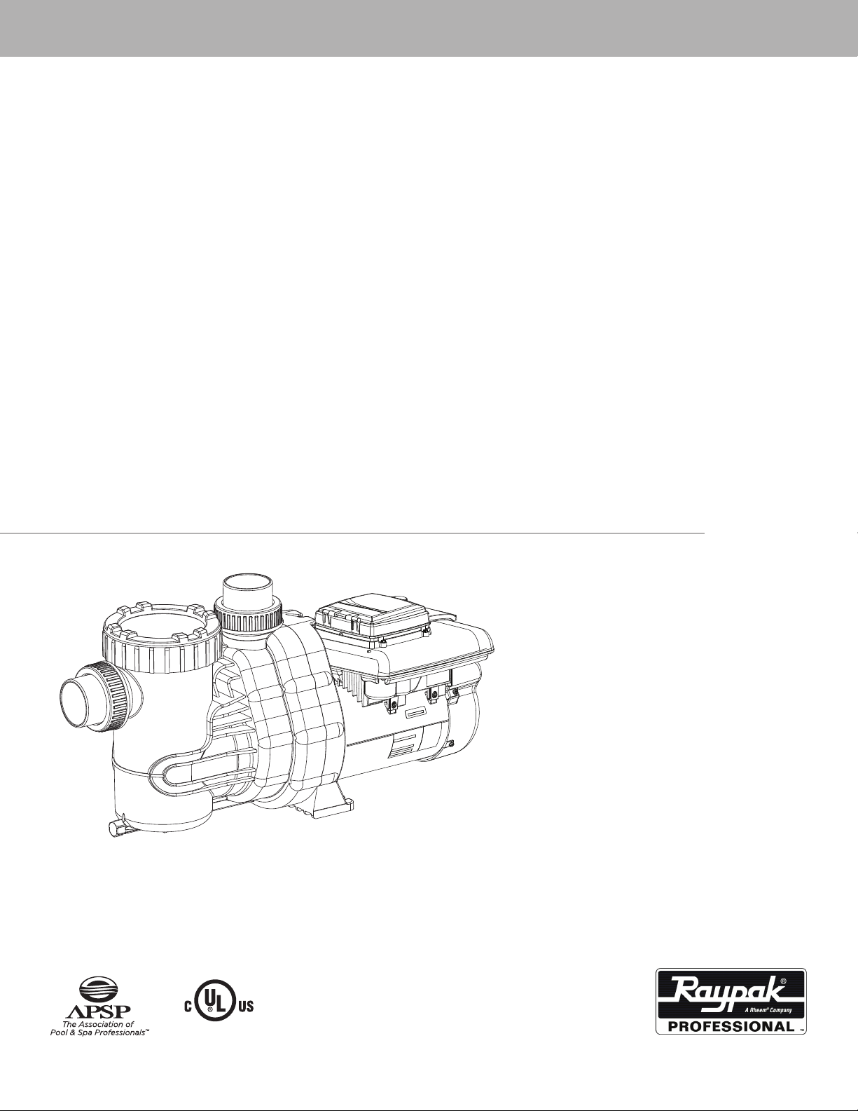
PS270VSP
Variable Speed Pool Pump
LISTED 31B4
Catalog No. 6000.556 Effective. 01/21/2013 Replaces: NEW P/N 241509 Rev 1
Page 2

Technical Support
Address: 7920 Interstate Court
North Ft. Myers, FL. 33917
Toll Free: 1-877-213-3726
Website: www.raypak.com
Manufactured for Raypak by Speck Pumps, Jacksonville Florida USA, © 2012-2013 All Rights Reserved.
This document is subject to change without notice.
Date of Installation:
Installed by:
Serial Number:
For Service Call:
Safety
Safety is emphasized throughout the user manual. These are safety alert symbols. They alert the user to
potential personal injury hazards. Obey all safety messages to avoid possible injury or death or damage
to equipment.
CAUTION
WARNING
DANGER
2999999294 - Rev 01/2013 v1
SAVE THESE INSTRUCTIONS!
Page 3

Table of Contents
1 Important Safety Instructions 5
2 General Description 7
3 Installation Information 9
Preparation Guide . . . . . . . . . . . . . . . 9
Pump Location . . . . . . . . . . . . . . . . 9
Pipe Sizing . . . . . . . . . . . . . . . . . . 10
Plumbing Installation . . . . . . . . . . . . . . 10
Bonding and Grounding . . . . . . . . . . . . . 10
Electrical Installation . . . . . . . . . . . . . . 11
Pressure Testing . . . . . . . . . . . . . . . . 13
4 Operation 13
Start-Up Guide . . . . . . . . . . . . . . . . 13
User Interface (Factory Default Schedule) . . . . . . 14
User Interface (Custom Schedule) . . . . . . . . . 14
Menu Structure . . . . . . . . . . . . . . . . 15
Setting the Clock. . . . . . . . . . . . . . . . 16
Setting the Schedule . . . . . . . . . . . . . . 16
Service . . . . . . . . . . . . . . . . . . . 17
Setup . . . . . . . . . . . . . . . . . . . . 18
Setup (Freeze Protection) . . . . . . . . . . . . 18
Setup (Auxiliary Load Setup) . . . . . . . . . . . 18
Setup (Prime Settings) . . . . . . . . . . . . . 19
Setup (Reset Factory Defaults) . . . . . . . . . . 20
Setup (Set Contrast) . . . . . . . . . . . . . . 20
Run (Schedule) . . . . . . . . . . . . . . . . 20
Override (Low) . . . . . . . . . . . . . . . . 21
Override (High) . . . . . . . . . . . . . . . . 22
Key Lockout Feature . . . . . . . . . . . . . . 23
Remote Mounting User Interface . . . . . . . . . 23
5 Service and Maintenance 25
Routine Maintenance . . . . . . . . . . . . . . 25
Winterizing . . . . . . . . . . . . . . . . . . 26
6 Troubleshooting 27
Fault LED . . . . . . . . . . . . . . . . . . 27
General Troubleshooting Problems . . . . . . . . 27
Blocked Impeller . . . . . . . . . . . . . . . . 28
Removal and Replacement of the Impeller . . . . . 29
Motor Replacement . . . . . . . . . . . . . . 30
Page 4

Table of Contents
7 Product Specications 30
Performance Curve & Dimensional Drawing . . . . . 31
Replacement Parts and Exploded View . . . . . . . 32
Page 5
1 Important Safety Instructions
READ THIS MANUAL CAREFULLY BEFORE USING THE PUMP
READ AND FOLLOW ALL INSTRUCTIONS!
Important Notice:
This manual contains important information about the installation, operation and safe use of this product.
This information should be given to the owner and/or operator of this equipment.
WARNING: This product must be installed and serviced by a qualied pool professional, and must
conform to all national, state, and local codes.
WARNING: Before Installing this product, read and follow all warning notices and instructions which are
included. Failure to follow safety warnings and instructions can result in severe injury, death, or property
damage. Call 1-877-213-3726 or visit www.raypak.com for additional copies of these instructions.
WARNING: California Proposition 65: This product contains chemicals known to the state of California to
cause cancer, birth defects or other reproductive harm.
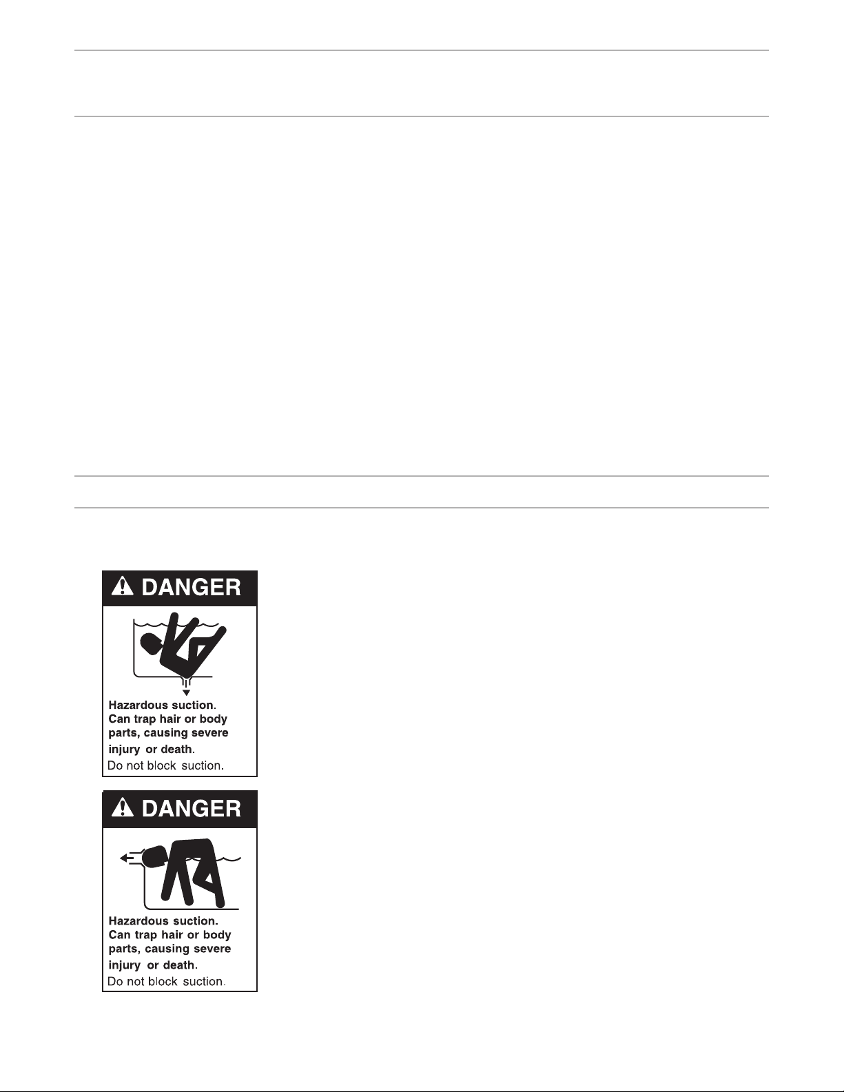
WARNING - Entrapment Prevention
DANGER: DO NOT BLOCK SUCTION
SUCTION HAZARD. Can cause serious injury or death. Do not use
this pump for wading pools, shallow pools, or spas containing bottom
drains, unless pump is connected to at least two (2) functioning suction
outlets.
WARNING: Pump suction is hazardous and can trap and drown
or disembowel bathers. Do not use or operate swimming pools,
spas, or hot tubs if a suction outlet cover is missing, broken, or
loose.
The following guidelines provide information for pump installation
that minimizes risk of injury to users of pools, spas, and hot tubs:
Entrapment Protection: The pump suction system must provide
protection against the hazards of suction entrapment.
Suction Outlet Covers: All suction outlets must have correctly installed,
screw-fastened covers in place. All suction outlet (drain) covers must be
maintained. Drain covers must be listed/certied to the latest published
edition of ANSI/ASME A112.19.8 (ANSI/APSP-16, 2011). They must be
replaced if cracked, broken, or missing.
Number of Suction Outlets Per Pump: Provide at least two (2)
hydraulically-balanced main drains, with covers, as suction for each
circulating pump suction line. The centers of the main drains (suction
outlets) on any one (1) suction line must be at least three (3) feet apart,
center to center.
5
Page 6

WARNING - Entrapment Prevention - continued
The system must be built to include at least two (2) suction outlets (drains) connected to the pump
whenever the pump is running. However, if two (2) main drains run into a single suction line, the single
suction line may be equipped with a valve that will shut off both main drains from the pump. The system
shall be constructed such that it shall not allow for separate or independent shutoff or isolation of each
drain.
More than one (1) pump can be connected to a single suction line as long as the requirements above are
met.
Water Velocity: The maximum water velocity through the suction tting or cover for any suction outlet
must be 1.5 feet per second, unless the outlet complies with the latest published edition of ANSI/ASME
A112.19.8 (ANSI/APSP-16, 2011), the standard for Suction Fittings For Use in Swimming and Wading
Pools, Spas, Hot Tubs, and Whirlpool Bathtub Applications. In any case, do not exceed the suction
tting’s maximum designed ow rate.
If 100% of the pump’s ow comes from the main drain system, the maximum water velocity in the pump
suction hydraulic system must be six (6) feet per second or less, even if one (1) main drain (suction
outlet) is completely blocked. The ow through the remaining main drain(s) must comply with the latest
published edition of ANSI/ASME A112.19.8 (ANSI/APSP-16, 2011), the standard for Suction Fittings For
Use in Swimming and Wading Pools, Spas, Hot Tubs, and Whirlpool Bathtub Applications.
Testing and Certication: Suction outlet covers must have been tested by a nationally recognized
testing laboratory and found to comply with the latest published edition of ANSI/ASME A112.19.8 (ANSI/
APSP-16, 2011), the standard for Suction Fittings For Use in Swimming and Wading Pools, Spas, Hot
Tubs, and Whirlpool Bathtub Applications.
Fittings: Fittings restrict ow; for best efciency use fewest possible ttings (but at least two (2) suction
outlets).
Avoid ttings that could cause an air trap.
Pool cleaner suction ttings must conform to applicable International Association of Plumbing and
Mechanical Ofcials (IAPMO) standards.
WARNING - Risk of Electrical Shock or Electrocution
This pool pump must be installed by a licensed or certied electrician or
a qualied pool serviceman in accordance with the National Electrical
Code and all applicable local codes and ordinances. Improper installation
will create an electric hazard which could result in death or serious injury
to pool users, installers, or others due to electrical shock, and may also
cause damage to property.
Always disconnect power to the pool pump at the circuit breaker
before servicing the pump. Failure to do so could result in death or
serious injury to serviceman, pool users, or others due to electric shock.
6
Page 7

Important Safety Instructions
When installing and using this electrical equipment, basic safety precautions should always be
followed, including the following:
READ AND FOLLOW ALL INSTRUCTIONS
WARNING: To reduce the risk of injury, do not permit children to use this product unless they are closely
supervised at all times.
WARNING: Risk of Electrical Shock. Connect only to a grounding type receptacle protected by a groundfault circuit-interrupter (GFCI). Contact a qualied electrician if you cannot verify that the receptacle is
protected by a GFCI.
The unit must be connected only to a supply circuit that is protected by a ground-fault circuit-interrupter
(GFCI). Such a GFCI should be provided by the installer and should be tested on a routine basis. To test
the GFCI, push the test button. The GFCI should interrupt power. Push the reset button. Power should be
restored. If the GFCI fails to operate in this manner, the GFCI is defective. If the GFCI interrupts power to
the pump without the test button being pushed, a ground current is owing, indicating the possibility of an
electric shock. Do not use this pump. Disconnect the pump and have the problem corrected by a qualied
service representative before using.
CAUTION: This pump is for use with permanently installed pools and may also be used with hot tubs
and spas if so marked. Do not use with storable pools. A permanently installed pool is constructed in or
on the ground or in a building such that it cannot be readily disassembled for storage. A storable pool is
constructed so that it may be readily disassembled for storage and reassembled to its original integrity.
TO REDUCE THE RISK OF ELECTRICAL SHOCK, connect ground wires to grounding screw located in
the motor. Use no smaller than a #12 AWG (3.3mm2) wire.
TO REDUCE THE RISK OF ELECTRICAL SHOCK, a bonding connector is provided for bonding to
metal water pipes, metal rails, or other metal within 5 feet of the swimming pool. All local points should be
bonded with a #8 AWG (8.4mm2) wire.
SAVE THESE INSTRUCTIONS.
2 General Description
Raypak Professional PS270VSP - Variable Speed
The PS270VSP is a premium efciency variable speed pump that provides tremendous exibility in speed
and time settings. Spurred by consumer interest in energy-saving products and government mandated
efciency standards, the innovative PS270VSP has such features as Power Factor Correction which
raises overall efciency while reducing input amps. The integration of a Real Time Clock and Auxiliary
Load Circuit (with congurable run time), eliminates the need for a separate timer making the installation
faster and easier for service contractors. The PS270VSP has programmable speeds from 600 – 3450
RPM (25 RPM increments) and two adjustable manual override speeds. The User Interface has step-bystep on-screen navigational prompts for faster set-up and programming ease.
7
Page 8
General Description - continued
The PS270VSP has the following features:
Integrated LCD backlight and adjustable contrast
Adjustable Freeze Protection
Congurable Prime Settings
Battery Backup – saves settings during a power outage
UV and rain-proof enclosure
Adjustable Manual High and Low Overrides
On Screen Status – including mode, time remaining, RPM, and energy efciency
Auxiliary Load Circuit with congurable run time
Noise Reduction Design
User Interface – Display can be mounted on or off board, facing the pump or facing the lead-in
POWER
W
E
R
O
P
OVERRIDE
LOW
S
A
6
OVERRIDE
HIGH
CLEAN
R
E
V
1
2
FAULT
3
BACK
5
+
SET
-
4
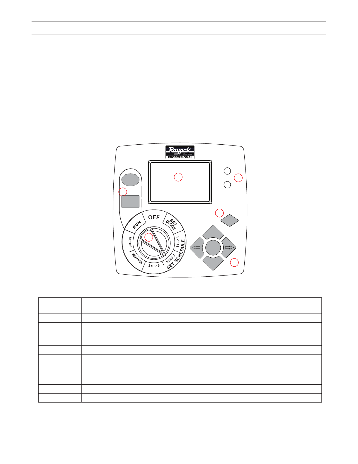
Figure 1
Controls and
LEDs
1 Display Screen
2 LED Lights
3 BACK: returns to previous program setting and does NOT accept current screen values
4 Navigation Selector
5 Interface Selector
6 Override Buttons
Description
Power: On Light (Green)
Fault: Light (Red)
+ or – increases/decreases selected value
← or → Navigates to adjustable value (digit)
SET accepts the current screen values
NOTE: The selector knob must be turned to RUN for the pump to operate. When the user presses ← or
→ the cursor moves to the next or previous position. If the cursor is at the end of a line when the user
presses the arrow, the cursor moves to the next line.
8
Page 9

3 Installation Instructions
Preparation Guide
1. Upon receipt of the pump, check the carton for damage. Open the carton and check the pump for
concealed damage, such as cracks, dents, or a broken base. If damage is found, contact the shipper or
distributor where the pump was purchased.
2. Inspect the contents of the carton and verify that all parts are included. See Section 7, Parts List and
Exploded View for details.
Pump Location
WARNING: This product must be installed and serviced by a qualied pool professional, and must
conform to all national, state, and local codes. Before installing this product, read and follow all warning
notices and instructions of this product. Failure to follow warning notices and instructions may result in
property damage, personal injury, or death.
ATTENTION INSTALLERS: This manual contains important information about the installation, operation,
and safe use of this product. This manual should be given to the owner/operator of this equipment.
1. Raypak recommends in order to achieve better priming, to install the pump as close to the pool as
practical and run suction lines as direct as possible to reduce friction loss.
2. It is recommended that a minimum length of straight pipe, equivalent to ve (5) times the pipe diameter
be used between the pump suction inlet and any plumbing ttings (elbows, valves, etc.).
3. Install the pump on a level, solid foundation which provides a rigid and vibration-free base. Secure the
pump to the base with screws or bolts to further reduce vibrations and stress on the plumbing.
4. Protect the pump against ooding and excess moisture. Select an area that will not ood when it rains.
DO NOT install the pump in a damp or non-ventilated location.
5. Keep the motor clean and provide free circulation of air for cooling.
6. Although the pump is designed for outdoor use, it is recommended to protect the pump from direct
sunlight and excessive moisture (rain, sprinklers, etc.).
7. DO NOT store or use gasoline or other ammable vapors or liquids in the vicinity of this pump. DO NOT
store pool chemicals near the pump.
8. DO NOT remove any safety alert labels such as DANGER, WARNING, or CAUTION. Keep safety
labels in good condition and replace any missing or damaged labels.
9. Provide access for future services by leaving a clear area around the pump. Allow plenty of space
above the pump to remove lid and basket for cleaning.
WARNING: Some Safety Vacuum Release System (SVRS) devices are not compatible with the installation
of check valves. If the pool has an SVRS device, be sure to conrm that it will continue to safely operate
when the check valves are installed.
9
Page 10

Pump Location - continued
NOTE: In Canada, the pump must be located a minimum of three (3) meters (approximately ten (10) feet)
from the water (CSA C22.1).
Pipe Sizing
NOTE: All pipe sizes are able to withstand the pressures the pump will deliver, but not necessarily the
ow. If the pipe is too small for the pump, or is elevated above water, the maximum gallons per minute
(GPM) may not be delivered. If this happens, the pump will develop a pocket of air (cavitation) that makes
noise. This may shorten the life of the pump.
SUCTION & DISCHARGE:
When the pump is located up to 50 feet from the pool, the recommended minimum pipe size for both the
suction and discharge is 2”.
For better efciency and less restriction, use as few ttings (elbows, tees, valves, etc.) as possible.
Suction line diameter must be equal or be greater than the discharge line diameter.
Suction and discharge lines should be independently supported at a point near the pump to avoid strains
being placed on the pump.
NOTE: If more than ten (10) suction ttings are needed, the pipe size must be increased.
Plumbing Installation
When installing the pump, care should be taken to see the suction line is below water level to a point
immediately beneath and in front of the pump to ensure quick priming via a ooded suction line. The
height between the pump and water level should not be more than ve (5) feet.
If the pump is located below water level, isolation valves must be installed on both sides of the pump to
prevent the back ow of pool water during any routine or required servicing. The PS270VSP - Variable
Speed comes equipped with unions on both the suction and discharge ports. This feature simplies
installation and service and eliminates the possibility of leaks at the threaded adaptors.
Before starting the pump for the rst time, remove the see-through lid. (Turn lid ring counter clockwise
to remove.) Fill strainer tank with water until it is level with the suction inlet. Replace lid, making sure the
o-ring is in place and not damaged. Screw down, hand tight.
Every new installation must be pressure tested according to local codes. See the Pressure Testing
Section on page 13.
Bonding and Grounding
WARNING: Ground and bond the pump before connecting to electrical power supply. Failure to ground
and bond the pump can cause serious or fatal electrical shock hazard. DO NOT ground to a gas supply
line. To avoid dangerous or fatal electrical shock, turn OFF power to the pump before working on electrical
connections.
10
Page 11
Bonding and Grounding - continued
1. The motor frame must be grounded to a reliable grounding point using a solid copper conductor, No. 8
AWG or larger. In Canada, No. 6 AWG or larger must be used. If the pump is installed within ve (5) feet
of the inside walls of the swimming pool, spa, or hot tub, the motor frame must be bonded to all metal
parts of the swimming pool, spa, or hot tub structure and to all electrical equipment, metal conduit, and
metal piping within ve (5) feet of the inside walls of the swimming pool, spa, or hot tub.
2. Bond the motor using the provided external lug.
WARNING: In order to avoid the risk of property damage, severe personal injury, and/or death, make
sure that the control switch, time clock, or control system is installed in an accessible location, so that in
the event of an equipment failure or loose plumbing tting, the equipment can be easily turned off.
CAUTION: The pump must be permanently connected to a dedicated electrical circuit. No other equipment,
lights, appliances, or outlets may be connected to the pump circuit, with the exception of devices that may
be required to operate simultaneously with the pump, such as a chlorinating device or heater.
Electrical Installation
WARNING: All electrical wiring must conform to the local NEC guidelines. A licensed, qualied
electrician should complete the wiring for this product.
Electrical Specications:
Voltage: 230 VAC +10%/-7%, Single Phase
Amps: 10.5
Speed Range: 600 – 3450 RPM
Power Factor: >90%
Peak Efciency: 88%
Ambient: 50
o
C
Environmental Rating: NEMA Type 3R
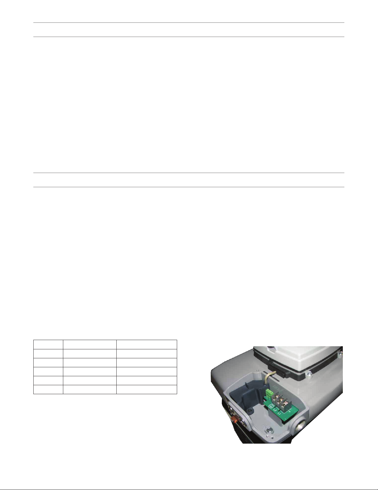
The controller is designed to operate with 230 Vrms, single phase power. For a direct wire connection,
the wire insulation should be stripped to a length of approximately 0.33” and the screw tightened to a
torque of 10 in-lb. The terminal block is capable of handling solid or stranded wire up to 12 AWG in size.
(See Table 1.0))
Table 1.0
Pin# Wire Color Description
L1 Black Hot 1
L2 Red or White Hot 2
GRD Green Ground
AUX1 Any Auxiliary 1
AUX2 Any Auxiliary 2
CAUTION: Voltage at the pump MUST NOT vary
by more than +10%/-7% of nameplate voltage.
Components may overheat, causing overload
tripping and reduced component life. Consult your
power company if this condition exists.
Note: Use only liquid tight ttings to protect the
electronics and motor.
Figure 2 - Terminal Box Cover Removed
11
Page 12

Electrical Installation - continued
115V
POWER
SOURCE
L1 (BLACK)
L2 (RED OR WHITE)
EARTH
Figure 3 - Wiring Diagram without AUX Load
230V
POWER
SOURCE
230V
POWER
SOURCE
115V
AUXILIARY
LOAD
Figure 4 - Wiring Diagram with 115V AUX Load
EARTH
LINE (BLACK)
230V
AUXILIARY
LOAD
L1 (BLACK)
L2 (RED OR WHITE)
EARTH
L2 (RED OR WHITE)
230V
POWER
SOURCE
12
Figure 5 - Wiring Diagram with 230V AUX Load
Page 13

Pressure Test
WARNING: To minimize the risk of severe injury or death, the lter and/or pump should not be subjected
to the piping system pressurization test.
Local codes may require the pool piping system to be subjected to a pressure test. These requirements
are generally not intended to apply to the pool equipment.
However, if the WARNING cannot be followed and pressure testing of the complete system must be
done, follow the following guidelines:
1. RELEASE ALL AIR in the system before testing.
2. Water pressure for the test must NOT EXCEED 35 PSI.
3. Water temperature for the test must NOT EXCEED 100° F (38° C).
4. Limit the test to 24 hours. After the test, visually check the system to be sure it is ready for operation.
DO NOT USE COMPRESSED AIR TO PRESSURE TEST OR CHECK FOR LEAKS.
4 Operation
Start Up Guide
CAUTION: Never run the pump without water. Running the pump “dry“ for any length of time can cause
severe damage to both the pump and the motor and will void the warranty.
If this is a new pool installation, make sure all piping is clear of construction debris and has been properly
pressure tested. The lter should be checked for proper installation, verifying that all connections and
clamps are secure according to the manufacturer’s recommendations.
WARNING: To avoid risk of property damage, severe personal injury or death, verify that all power is
turned off before starting this procedure.
1. Depending on the location of the pump, do one of the following:
If the pump is located below the water level of the pool, open the lter pressure valve the prime
the pump with water. Once all the air has left the lter, close the lter pressure release valve.
If the pump is located above the water level of the pool, remove the lid and ll the basket with
water before starting the pump.
2. Prior to replacing the lid, check for debris around the lid o-ring seat. Debris around the lid o-ring seat
will make it difcult to prime the pump.
3. Hand-tighten the lid to make an air tight seal. Do not use any tools to tighten the lid: hand-tighten
only. Make sure all valves are open and the unions are tight.
4. Restore power to the system.
13
Page 14

User Interface (Factory Default Schedule)
The PS270VSP is programmed with a pre-set schedule. Only the clock setting is required to enable the
PS270VSP to operate.
Table 2.0 - Factory Default Schedule
STEP 1 STEP 2 STEP 3
SPEED 3450 RPM 2600 RPM 1725 RPM
START TIME 8:00 AM 11:00 AM 1:00 PM
STOP TIME 11:00 AM 1:00 PM 9:00 PM
1. Turn Selector Knob to Set Clock. (See Figure 1)
2. Set the Time and Date using the +, -, ← and → buttons.
3. Turn the Selector Knob to Run.
NOTE: You must wait until “Prime Mode” is complete to make changes to OVERRIDE settings.
4. (Self Priming Pump) Open the lter pressure relief valve until all air has escaped and then close.
5. If pump does not prime and all instructions to this point have been followed, check for a suction leak.
Repeat process.
6. For technical assistance call, Technical Support at 1-877-213-3726.
User Interface (Custom Schedule)
The green Power On LED illuminates when the unit is powered on.
The red Fault LED illuminates when a fault occurs.
Use the ← and → arrow buttons to select menu areas.
Use the + and – to change menu selection parameters.
1. Turn Selector Knob to SET CLOCK.
2. Adjust the Time and Date.
3. Turn the Selector Knob to SET SCHEDULE (STEP 1, 2, 3)
4. Set the Motor Speed, Start, and Stop times for STEP 1, 2, 3.
5. Turn the Selector Knob to SETUP (Use ← and → to scroll thru SETUP items)
Enable/Disable Freeze Protection
Set Display Screen Contrast
Set External Relay Speed and Time
Set Prime Speed and Duration
Reset Factory Defaults (Will return programmed schedule to Factory Defaults)
6. Turn Selector Knob to RUN.
7. Press OVERRIDE HIGH button (Not required to run normal schedule)
14
Page 15

User Interface (Custom Schedule) - continued
8. Press SET to change OVERRIDE HIGH speed and duration.
9. Press OVERRIDE LOW button (Not required to run normal schedule)
10. Press SET to change OVERRIDE LOW speed and duration.
Menu Structure
1. SET CLOCK
a. Date and Time
2. STEP 1 (Set Schedule)
a. Speed, Start Time, Stop Time
3. STEP 2 (Set Schedule)
a. Speed, Start Time, Stop Time
4. STEP 3 (Set Schedule)
a. Speed, Start Time, Stop Time
5. SERVICE
a. UNIT SERIAL NUMBER
b. DC CAP VOLTAGE
c. IGBT TEMPERATURE
d. PCB TEMPERATURE
e. FAULT HISTORY (1, 2, 3, 4)
f. CONTROLLER SOFTWARE VERSION
g. INTERFACE SOFTWARE VERSION
6. SETUP
a. FREEZE PROTECTION
i. Enabled/Disabled
ii. Turn ON Temperature
b. AUX LOAD SETUP
i. Minimum Turn On Speed
ii. Maximum Run Time (in 24 hours)
c. PRIME CONFIGURATION
i. Speed
ii. Time
d. RESET FACTORY DEFAULTS
i. Yes/No
e. SET CONTRAST
7. RUN
a. MANUAL OVERRIDE HIGH
i. Speed and Duration
b. MANUAL OVERRIDE LOW
i. Speed and Duration
8. OFF
15
Page 16

Setting the Clock
NOTE: The clock must be set the rst time the pump is
powered-up for proper operation.
1. Turn the Selector Knob to SET CLOCK. (See Figure
W
E
R
O
6)
2. At any time, the user can press BACK to return to
the previous screen.
3. Press + or – to change the Month. Press → to move
P
OVERRIDE
LOW
S
A
V
OVERRIDE
HIGH
CLEAN
11/11/2011
R
E
11:26 AM
SET CLOCK
to the Day setting.
4. Press the + or – to change the Day. Press → to
move to the Year setting.
5. Press + or – to change the Year. Press → to move
to the Hour setting.
6. Press + or – to change the Hour. Press → to move
Figure 6 - Set Clock Menu Buttons
to the Minute setting.
7. Press + or – to change the Minute. Press → to move to the AM or PM setting.
8. Press SET when the time is correct.
POWER
FAULT
BACK
+
SET
-
9. Press SET again if the user needs to make additional changes. The cursor returns to the Month setting.
10. If the date and time are correct, turn the Selector Knob to SET SCHEDULE, STEP 1.
Setting the Schedule
NOTE: Neither of the OVERRIDE buttons can be programmed from the SET SCHEDULE. The message
“Invalid Key” appears if the user presses an Override button.
Set the Speed and Start/Stop times for the pump in the
Set Schedule menu. The schedule is based on a 24hour clock and will repeat each day of the week.
Table 3.0 - Record Schedule
Record Schedule
STEP 1 STEP 2 STEP 3 OVERRIDE
Speed (RPM)
Start Time
Stop Time
W
O
P
OVERRIDE
LOW
S
A
V
OVERRIDE
HIGH
CLEAN
E
E
ENERGY USAGE 100%
R
SPEED
START TIME
R
STOP TIME
SET SCHEDULE STEP1
3450RPM
08:00AM
11:00AM
POWER
FAULT
BACK
+
By writing down the planned schedule, it will make the
programming process easier and will help the user to
remember the user’s settings in case the programming
is inadvertently lost. The User Interface will not allow
the user to program an overlap between different steps
of the schedule. The most recent setting will always
take priority over any previous settings.
Figure 7 - Set Schedule - STEP 1
SET
-
16
Page 17

Setting the Schedule - continued
1. Turn the Selector Knob to SET SCHEDULE, STEP 1. (See Figure 7)
2. The rst digit in the Speed setting ashes. Press + or – to change the rst digit in the Speed setting.
The number increases one unit at a time.
3. Press → to move to the second digit in the Speed setting. Press + or – to change the second digit. The
number increases one unit at a time.
4. Press → to move to the third digit in the Speed setting. Press + or – to change the third digit. The
number increases one unit at a time.
5. Press → to move to the fourth digit in the Speed setting. Press + or – to change the fourth digit. The
number increases ve units at a time.
6. Press → to move to the Start Time setting.
7. Press the + or – to change the Hour. Press → to move to the Minute setting.
8. Press the + or – to change the Minute. Press → to move to the AM or PM setting.
9. Press → to move to the Stop Time setting. Follow steps 6 through 8 to set the Stop Time settings.
10. Press Set to save the settings. If necessary, press SET again to move the cursor back to the rst digit.
Unless changes are necessary, move the Selector Knob to STEPS 2 and 3 and repeat steps 2 - 10.
Service
The SERVICE menu allows the user to view, but not change, the following information.
Unit model number and serial number
User Interface Version number
Controller Software Version
The four most recent faults
PCB Temperature
IGBT Temperature
DC Cap Voltage
Press the arrows to navigate between items viewed on the display screen. (See Figure 8)
BACK
Figure 8 - Service Menu
+
SET
-
17
Page 18

Setup
SETUP allows the user to congure the following parameters:
Freeze Protection
Auxiliary Load Settings
Prime Settings
Reset Factory Defaults
Set Contrast Level
Setup (Freeze Protection)
Freeze Protection can be either enabled or disabled
when the user turns the User Interface Selector Knob
to SETUP. If it is enabled, the user will be able to set
the temperature at which the pump will turn on. The
control is designed to run the pump for 8 hours at 2600
RPM if the temperature drops below the set point (the
default temperature is 39
o
F).
1. Turn the Selector Knob to SETUP.
2. Press either + or – to change the Freeze Protection
setting. Press SET to save any changes.
W
E
O
P
OVERRIDE
LOW
S
A
E
V
OVERRIDE
HIGH
CLEAN
11:26AM
R
Freeze Protection
R
TURN ON AT
39 F (003 C)
SETUP MENU
POWER
ENABLED
FAULT
BACK
+
WARNING: Freeze Protection will ONLY function with
the Selector Knob in the RUN position. Damage may
occur to the user’s pool system if Freeze Protection is
enabled and the switch is not in the RUN position.
Setup (Auxiliary Load Setup)
The Auxiliary Load is a relay inside the control designed
to provide AC power to a load that should not be
energized without adequate water ow from the pump
(i.e. heater, boost pump, salt water chlorinator).
The control is designed to turn on the Auxiliary Load
relay when the pump speed is above the MINIMUM ON
SPEED (default is 2000 RPM). The Auxiliary Load relay
will stay closed as long as the pump speed is above
the MINIMUM ON SPEED. In addition, the control can
be programmed to limit the amount of time the Auxiliary
Load relay is closed in a 24-hour period. For example,
if the pump runs at 3450 RPM for 12 hours a day,
but the auxiliary load only needs to be powered for 6
hours, the user can set the MAXIMUM RUN TIME. Two
examples of different settings are provided in Table 4.0
and Table 5.0.
Figure 9 -
W
E
R
O
P
OVERRIDE
LOW
S
R
A
E
V
OVERRIDE
HIGH
CLEAN
Freeze Protection
11:26AM
AUX LOAD SETUP
MIN ON SP: 2000RPM
MAX RUN: 10.5Hr(s)
SETUP MENU
SET
-
POWER
FAULT
BACK
+
SET
-
1. Turn the Selector Knob to SETUP. (See Figure 10)
18
Figure 10 - Auxiliary Load
Page 19

Setup (Auxiliary Load Setup) - continued
2. Press → one time to change the Auxiliary Load settings. Press SET to enter “change mode.” Press +
or – to increase or decrease the Minimum Speed. Press → to change the Maximum Run Time. Press the
+ or – to increase or decrease the Maximum Run Time. Press SET to save changes.
Table 4.0 - Auxiliary Load Setup Example #1
Pump Motor Settings Aux. Load Settings
STEP 1 STEP 2 STEP 3
Speed 3450 RPM 2600 RPM 1725 RPM
Start Time 8:00 AM 11:00 AM 1:00 PM
Stop Time 11:00 AM 1:00 PM 9:00 PM
MIN ON SPEED 2000 RPM
MAX RUN TIME 10.5 Hours
Total run time for pump motor 13 Hours
Total run time for AUX. Load 5 Hours
Table 5.0 - Auxiliary Load Setup Example #2
Pump Motor Settings Aux. Load Settings
STEP 1 STEP 2 STEP 3
Speed 3450 RPM 2600 RPM 1725 RPM
Start Time 8:00 AM 4:00 PM 8:00 PM
Stop Time 4:00 PM 8:00 PM 11:00 PM
MIN ON SPEED 2000 RPM
MAX RUN TIME 10.5 Hours
Total run time for pump motor 15 Hours
Total run time for aux. load 10.5 Hours
Setup (Prime Settings)
The priming speed and time can be adjusted within
this menu. The minimum priming speed is 1500 RPM.
The maximum priming time is 10 minutes. (NOTE:
The factory default is 2600 RPM for 1 minute.)
1. Turn the Selector Knob to SETUP.
2. Press → two (2) times to change the Prime
settings.
3. Press SET to enter “change mode.”
4. Press + or – to increase or decrease the Prime
Speed.
5. Press → to change the Prime Time.
W
O
P
OVERRIDE
LOW
S
A
V
OVERRIDE
HIGH
CLEAN
E
R
E
11:26AM
Prime Configure
R
Speed: 2600 RPM
Time: 01 min(s)
SETUP MENU
POWER
FAULT
BACK
+
SET
-
6. Press the + or – to increase or decrease the
Figure 11 - Prime Conguration
Maximum Run Time. Press SET to save changes.
Note: If the pump fails to prime it will activate the fault code “Prime Failure” and the control will retry.
19
Page 20

Setup (Reset Factory Defaults)
This menu will permit the user to reset all settings in the
control to the factory default settings.
1. Turn the Selector Knob to SETUP.
2. Press → three (3) times to Reset to Factory Default
settings.
3. Press SET two (2) times to verify intent to Reset to
the Factory Default settings.
Setup (Set Contrast)
This menu will change the contrast of the LCD screen
to optimize viewing for various lighting conditions.
Ensures the display can be viewed easily in dark,
shady, or direct sunlight conditions.
1. Turn the Selector Knob to SETUP.
2. Press → four (4) times to change the Contrast
setting. Use + and – to adjust the contrast level.
3. Press SET to save the setting.
W
O
P
OVERRIDE
LOW
S
A
V
OVERRIDE
HIGH
CLEAN
E
E
11:26AM
R
Reset Factory
R
SETUP MENU
No
Figure 12 - Factory Defaults
W
O
P
OVERRIDE
LOW
S
A
V
OVERRIDE
HIGH
CLEAN
E
E
11:26AM
R
Set Contrast
R
SETUP MENU
45%
POWER
FAULT
BACK
+
SET
-
POWER
FAULT
BACK
+
SET
-
Figure 13 - Set Contrast
Run (Schedule)
The display screen in the RUN switch position shows the following.
Current clock time
Remaining time
Which Step or Prime is running and at what RPM
Pump status (for example, Program Running)
Pump “RUN” allows the user to set the Override parameters. Run the Override settings if the pump needs
to perform a certain function immediately. (Example: vacuuming)
20
Page 21

Run (Schedule) - continued
If the user presses +, -, ←, or → the message “Speed
and Time Cannot be Changed” appears.
If the user presses the Back button the message
“Speed and Time Cannot be Changed” appears
unless an Override setting is running.
W
O
P
OVERRIDE
LOW
S
A
V
OVERRIDE
HIGH
CLEAN
E
R
E
11:26AM
SCHEDULE RUN: STEP3
1725RPM 05H28MLEFT
R
Energy 016% 0071W
POWER
FAULT
BACK
+
SET
-
Figure 14 - Run Screen
Override (Low)
The OVERRIDE LOW button can program the motor to temporarily run at speeds between 600 and
3450 RPM. Override Low is recommended for low circulation requirements that exist outside of the daily
operating schedule. Once the Override Low duration is completed, the motor will automatically return to
the programmed schedule.
NOTE: Press + to increase the speed. If the value is
at 3450, the screen reads “Maximum Speed for this
Motor is 3450 RPM.” If the fourth digit is ashing,
press + and the speed increases by 5. If the third
digit is ashing and the value of the speed is 3445
then the speed increases to 3450. If the third digit is
ashing and is less than 3445, the speed increases
by 10. If the second digit is ashing and greater
than or equal to 3350, the speed increases to 3450.
If the third digit is ashing and less than 3350, the
speed increases by 100. If the rst digit is greater
than or equal to 2450, the speed increases to 3450.
W
O
P
OVERRIDE
LOW
S
A
V
OVERRIDE
HIGH
CLEAN
E
R
E
11:26AM
OVERRIDE RUN: LOW
1725RPM 08H00MLEFT
R
Energy 045% 0062W
POWER
FAULT
BACK
+
SET
If the rst digit is ashing and less than 2450, the
speed increases by 1000. Hold + and the values
-
increase rapidly.
Figure 15 - Override Low Screen
Press – to decrease the speed. If the value is at 0 RPM, the screen reads “Minimum Speed for this Motor
is 0 RPM.” If the value of the high speed is 600 then it decreases to 0 RPM. If the fourth digit is ashing,
press – and the speed decreases by 5. If the third digit is ashing and the value of the speed is 605, the
speed decreases to 600. If the third digit is ashing and greater than 605, the speed decreases by 10. If
the second digit is ashing and less than or equal to 700, the speed decreases to 600. If the second digit
is ashing and greater than 700, the speed decreases by 100. If the rst digit is less than or equal to 1600,
the speed decreases to 600. If the rst digit is ashing and greater than 1600, the speed decreases by
1000. Hold – and the values decrease rapidly.
21
Page 22

Override (Low) - continued
1. Press OVERRIDE LOW button.
2. Press SET to change the Override Low settings.
3. Press + or – to increase or decrease the rst digit in the speed. The maximum speed is 3450 RPM and
the minimum speed is 600 RPM.
4. Press → to move to the second, third, and fourth digits in the speed.
5. Press SET to save the speed setting. The motor runs at the Override Low setting. The Override Low
Duration Time setting ashes.
6. Press + or – to increase or decrease the Override Low Duration Time. The maximum duration is 24
hours and the minimum is 0.5 hours (half an hour).
7. Press SET to save the Override Low Duration Time setting.
Override (High)
The OVERRIDE HIGH button can program the pump to temporarily run at speeds between 600 and 3450
RPM. OVERRIDE HIGH is recommended for high ow uses such as a pool heater startup, backwash,
ltering, and cleaner water requirements that exist outside of the daily operating schedule. Once the
Override High duration is completed, the pump will automatically return to the programmed schedule.
NOTE: Press + to increase the speed. If the value is
at 3450, the screen reads “Maximum Speed for this
Motor is 3450 RPM.” If the fourth digit is ashing, press
+ and the speed increases by 5. If the third digit is
ashing and the value of the speed is 3445 then the
speed increases to 3450. If the third digit is ashing
and is less than 3445, the speed increases by 10. If
the second digit is ashing and greater than or equal
to 3350, the speed increases to 3450. If the third digit
is ashing and less than 3350, the speed increases by
100. If the rst digit is greater than or equal to 2450, the
speed increases to 3450. If the rst digit is ashing and
less than 2450, the speed increases by 1000. Hold +
W
O
P
OVERRIDE
LOW
S
A
V
OVERRIDE
HIGH
CLEAN
E
E
11:26AM
R
OVERRIDE RUN:HIGH
3450RPM 02H00MLEFT
R
Energy 100% 0161W
POWER
FAULT
BACK
+
SET
and the values increase rapidly.
-
Figure 16 - Override High Screen
Press – to decrease the speed. If the value is at 0 RPM, the screen reads “Minimum Speed for this Motor
is 0 RPM.” If the value of the high speed is 600 then it decreases to 0 RPM. If the fourth digit is ashing,
press – and the speed decreases by 5. If the third digit is ashing and the value of the speed is 605, the
+ speed decreases to 600. If the third digit is ashing and greater than 605, the speed decreases by 10.
If the second digit is ashing and less than or equal to 700, the speed decreases to 600. If the second
digit is ashing and greater than 700, the speed decreases by 100. If the rst digit is less than or equal to
1600, the speed decreases to 600. If the rst digit is ashing and greater than 1600, the speed decreases
by 1000. Hold – and the values decrease rapidly.
22
Page 23

Override (High) - continued
1. Press OVERRIDE HIGH button.
2. Press SET to change the Override High settings.
3. Press + or – to increase or decrease the rst digit in the speed. The maximum speed is 3450 RPM and
the minimum speed is 600 RPM.
4. Press → to move to the second, third, and fourth digits in the speed.
5. Press SET to save the speed setting. The motor runs at the Override High setting. The Override High
Duration Time setting ashes.
6. Press + or – to increase or decrease the Override High Duration Time. The maximum duration is 24
hours and the minimum is 0.5 hours (half an hour).
7. Press SET to save the Override High Duration Time setting.
Key Lockout Feature
The PS270VSP User Interface has a key lockout feature to prevent unwanted changes to the settings. To
lock the keys, hold down the “+, -, and SET” buttons for more than 3 seconds. The display will then show
a symbol of a key indicating the buttons are locked. The user can unlock the keys by holding down the
same buttons for more than 3 seconds.
Remote Mounting User Interface
The PS270VSP user interface can be mounted remotely from the controller. In order to complete this
procedure, the following steps should be followed:
1. Remove main power from the controller.
2. Remove the terminal box cover from the controller
(two screws).
Table 6.0 - RS485 UI Remote Mount Connections
Pin # Wire Color Description
1 Red +10 V
2 Green RS485-A
3 Black RS485-B
4 Yellow Isolated Ground
Figure 17 - Terminal Box Cover Removed
23
Page 24

Remote Mounting User Interface - continued
3. Remove the plastic wiring cover inside the terminal
box (one screw).
4. Disconnect the 4-pin communication connector
(J103) by pulling up on the connector.
Figure 18 - Internal Plastic Cover Removed
5. Install a longer cable of the desired length to the
J103 connector on the controller.
6. Replace the plastic cover inside the terminal box
(one screw).
Figure 19 - Communication Connector Removed
Figure 20 - UI Connector Installed
24
Figure 21 - Plastic Cover Installed in Terminal Box
Page 25

Remote Mounting User Interface - continued
7. Replace the metal terminal box cover. It is VERY
IMPORTANT to make sure the communication cable
ts into the slot on the terminal box cover BEFORE
the screws are tightened. This will prevent the cable
from being damaged.
8. Remove the small cover on the back of the User
Interface (two screws).
9. Remove the 4-pin connector from the CN1 connector
on the User Interface.
Figure 22 - Wire Routing
10. Attach the other end of the longer cable to the CN1
connector on the User Interface.
11. Replace the small cover on the back of the User
Interface.
12. Mount the User Interface to the desired location
(i.e. wall, post, fence, etc.)
Optional kit for mounting the User Interface remotely: PN: 2512723-001
However, it is not mandatory to purchase this kit to mount the User Interface remotely.
Figure 23 - Cover Installed
5 Service and Maintenance
The PS270VSP is very reliable and robust in harsh environments. However, this product does contain
electronics that are cooled by a fan mounted to the motor. In order to ensure optimum reliability of this
product, it is recommended to clean the fan inlet on the back of the motor once a month. It is important to
keep this area free of large debris such as leaves, branches, mulch, plastic bags, etc.
Routine Maintenance
This pump requires little or no service other than reasonable care and periodic cleaning of the strainer
basket.
1. Inspect the pump basket for debris by looking through the clear pump lid.
25
Page 26

Routine Maintenance - continued
2. Turn off the power to the pump. If the pump is located below the water level, close isolation valves on
the suction and discharge sides of the pump to prevent back ow of water.
3. Remove any debris, because as the debris accumulates, it will begin to block the ow of water through
the pump. Keep the basket clean and clear to improve the performance of the pump.
4. Turn the lid’s lock ring counter clockwise until it stops. Carefully remove the lid and lock ring.
5. Remove the basket and properly dispose of the debris into the trash and rinse out the basket. Check
basket for cracks, if crack is found replace basket.
6. Replace basket back into the pump, align the basket properly with the suction pipe. Then ll with water
up to the suction pipe. Clean clear cover, lid o-ring and sealing surface of the pump of any debris.
7. Replace lid with locking ring. Hand-tighten the lid to make an air-tight seal. Do not use any tools to
tighten the lid.
8. Verify that all valves have been returned to the proper position for normal operation. Turn on the power
to the pump.
Winterizing
CAUTION: The pump must be protected when freezing temperatures are expected. Allowing the
pump to freeze will cause severe damage and void the warranty.
There are two options when winterizing the pump
Option 1:
1. Drain all the water from the pump, system equipment, and piping.
2. Remove drain plugs. Do not replace plugs. Store the plugs in the empty strainer basket for winter.
3. Keep the motor covered and dry.
Option 2:
1. Drain all the water from the pump, system equipment, and piping.
2. Remove the pump and motor from the plumbing and store indoors in a warm and dry location.
Note: After removing the pump, cover open plumbing connections to prevent intrusion of any foreign
objects.
Note: When the winter season is over the pump will need to be primed prior to start. Refer to Section 4
Operation, Start Up Guide.
CAUTION: DO NOT run the pump dry. If the pump is run dry, the mechanical seal will be damaged and the
pump will start to leak at the seal. If this occurs, the mechanical seal will need to be replaced. ALWAYS
maintain the proper water level in your pool. Continued operation in this manner could cause a loss of
pressure, resulting in damage to the pump casing, impeller, and mechanical seal (voiding warranty).
26
Page 27

6 Troubleshooting
Fault Codes - Fault LED (Red)
WARNING: The pump must be serviced by a professional service technician qualied in pool/spa
installation. The following procedures must be followed exactly. Improper installation and/or operation
can create dangerous electrical hazards, which can cause high voltage to run through the electrical
system. This can cause property damage, serious personal injury, and/or death. Improper installation
and/or operation will void the warranty.
The red Fault LED illuminates when a fault occurs. Turn the Selector Knob to SERVICE and use the ←
and → arrow buttons to select and view the last four fault codes.
Display (Fault Code) Description Controller Action
SW Over current Software over current Control will retry
HW Over current Hardware over current Control will retry
DC Over voltage DC capacitor over voltage Control waiting for voltage to drop
DC Under voltage DC capacitor under voltage Control waiting for voltage to rise
PCB Temperature Printed circuit board over temperature Control waiting for temperature to drop
IGBT Temperature Inverter IGBT over temperature Control waiting for temperature to drop
Imbalance Current Motor current imbalance Control will retry
Prime Failure Failure to Prime Pump Control will retry
Startup Failure Failure to Start Pump Control will retry
Low Power Low power Control will retry
Loss of Phase Loss of phase Verify motor connected. Control will retry
Processor Failure Processor failure Control will retry
POWERING DOWN Power down
Generic Fault All other faults Control will retry
If the motor does not restart following motor retry, please contact your service professional.
Note: The fault message “Communication Error, Check Connections” appears if the user interface is
unable to establish communications with the controller within ve seconds.
General Pump Troubleshooting
Problem Possible Cause Solution
1. Pump will not prime. A. Suction air leak
B. No water in pump.
C. Closed valves or blocked lines.
D. Low voltage to motor.
Make sure see-through lid and o-rings
are clean and properly positioned.
Hand tighten see-through lid. Tighten
all pipes and ttings on suction side
of pump. Be sure water in pool is high
enough to ow through skimmer.
Make sure strainer tank is full of water.
Open all valves in system. Clean
skimmer and strainer tank. Open pump
and check for clogging of impeller.
Check voltage at motor. If low, pump
will not come up to speed.
27
Page 28

General Pump Troubleshooting - continued
Problem Possible Cause Solution
2. Motor Fails to Start A. No power to motor.
Check that all power switches are
on. Be sure fuse or circuit breaker is
properly set. Time set properly? Check
motor wiring at terminal.
B. Pump jammed
C. Controller DIP switches not congured properly
3. Motor Runs then Stops A. Over temperature fault
B. Over current fault
4. Motor is noisy A. Debris in contact with fan
B. Debris in strainer basket
C. Loose mounting
5. Motor Runs, but no ow A. Impeller is loose
B. Air Leak
With power off, turn shaft. It should
spin freely. If not, disassemble and
repair.
Verify that the DIP switches are in the
correct position.
Check the back of the motor is free
from dirt and debris.
Motor will automatically restart after
one minute.
Check that the back of the motor is
free from dirt and debris.
Clean strainer basket.
Check that the mounting bolts are tight.
Check that motor is spinning by looking at the fan on the back of the motor.
If so, check that pump impeller is correctly installed and undamaged.
Check plumbing connections and verify
they are tight.
C. Clogged or restricted plumbing
D. Dirty Filter
Check for blockage in strainer or suction side piping.
Check for blockage in discharge piping
including partially closed valve or dirty
pool lter.
Back wash lter when pressure is high,
or clean cartridges.
Blocked Impeller
WARNING: Before servicing the pump, switch off the circuit breakers at the power source. Severe
personal injury or death may occur if the pump starts while your hand is inside the pump.
1. Turn off the pump. Switch off the circuit breaker to the pump motor.
2. Remove the pump lid and strainer basket.
3. Look inside pump for debris. Remove any debris found inside.
4. Replace the strainer basket and lid.
5. Switch on the circuit breaker to the pump motor.
28
Page 29

Blocked Impeller - continued
6. Turn on the pump, see if the problem is resolved.
7. If the impeller is still blocked with debris and it is not possible to remove the debris using Steps 2 - 4,
the pump will need to be disassembled in order to access the inlet and outlet of the impeller.
Removal and Replacement of the Impeller and/or Mechanical Seal
WARNING: Before servicing the pump, switch off the circuit breakers at the power source. Severe
personal injury or death may occur if the pump starts while your hand is inside the pump.
1. Turn off the pump. Switch off the circuit breaker to the pump motor. If you are not replacing the motor,
do not disconnect the electrical wiring.
2. Turn off any valves to prevent pool water from reaching the pump. Drain water from the pump by
loosening the unions or removing the drain plugs.
3. Remove the ten (10) screws connecting the pump casing to the ange.
4. Pull the motor, seal housing, ange out from the pump casing. Remove the pump casing o-ring. The
impeller is connected to the motor shaft.
5. Remove the diffuser by gently pulling the diffuser (the
diffuser is the cover over the impeller) horizontally until
the pins clear the seal housing.
Impeller
6. Place a 5/16” Allen head wrench through the center
Ceramic Ring
Shaft
Rubber Collar
hole of the fan cover and into the recess on the end of
motor shaft.
Spring
Assembly
Sealing
Surfaces
7. While holding the motor shaft, turn the impeller counterclockwise.
Figure 25
8. Gently pull the mechanical seal from the impeller shaft noting the way it was originally installed.
CAUTION: Do not damage the ceramic or carbon surfaces of the seal. If the surfaces are damaged,
leaks will occur.
9. Using water with a small amount of dish soap, brush the impeller shaft for ease of assembly.
10. With the carbon side up, push the mechanical seal onto the impeller shaft and wipe carbon surface
with a clean cloth.
CAUTION: Do not use grease or lube to install seal. It will damage the seal and cause failure.
Pump Seal Housing
11. The ceramic side of the seal can be pushed out from the rear of the seal housing. Please note its
position before removing.
12. Using water only, wet the ceramic side of the seal and using your thumbs push into the seal housing.
Clean surface with a clean cloth.
13. Wipe the motor shaft of all debris. Re-install the seal housing and apply a single drop of Loctite to
the motor shaft threads.
29
Page 30

Removal and Replacement of the Impeller and/or Mechanical Seal - continued
14. Install impeller by spinning it clockwise onto the motor shaft. Continue to turn clockwise until the
carbon and ceramic sides make contact and the seal spring slightly compresses.
15. Install the diffuser by aligning the diffuser pin with the holes in the seal housing and pressing together.
16. Make sure the diffuser and casing o-rings are in place and free of debris. Reassemble in reverse,
sliding the seal housing back into the casing.
17. Tighten (torque of 8 Nm or 70.8 in-lb.) the ten (10) screws using a cross pattern from side to side and
top to bottom.
CAUTION: Do not over-tighten or you will strip the casing threads.
Motor Replacement
WARNING: The pump must serviced by a professional service technician qualied in pool/spa installation.
The following procedures must be followed exactly. Improper installation and/or operation can create
dangerous electrical hazards, which can cause high voltage to run through the electrical system. This
can cause property damage, serious personal injury, and/or death. Improper installation and/or operation
will void the warranty.
1. Disconnect the wiring from the side of the motor. (Refer to the Electrical Installation)
2. Remove the ten (10) screws holding the ange to the pump casing.
3. Slide the motor and ange from the casing.
4. Remove the diffuser by gently pulling the diffuser horizontally until the pins are clear from the seal
housing.
5. Place a 5/16” Allen head wrench through the center hole of the fan cover and into the recess on
the end of the motor shaft.
6. While holding the motor shaft, turn the impeller counter-clockwise.
7. After removal of the impeller, the seal housing will slide easily off the motor shaft.
8. Using a athead screwdriver, remove the four bolts and washers securing the ange to the motor.
9. Clean the surfaces of the seal (Refer to the Removal and Replacement of the Impeller and/or
Mechanical Seal Section page 29-30 steps 9 -17).
7 Product Specications
Dimensional Drawing
30
Page 31

Dimensional Drawing - continued
28.0"
8.9"
Performance Curve
90
3450 RPM
80
70
3100 RPM
60
2850 RPM
50
2600 RPM
2350 RPM
40
12.1"
16.6"
17.0"
6.8"
13.6"
4.3"
0.4"
5.1"
6.9"
9.7"
B
CA
D
12.7"
2100 RPM
TOTAL HEAD IN FEET
30
1850 RPM
20
1600 RPM
1350 RPM
10
1100 RPM
850 RPM
600 RPM
0
20 40 60 80 100 120 140 160 180 200
GALLONS PER MINUTE
B, A, C, and D represent average system curves for pools
with the pipe diameter mentioned below.
1
/
B = 1
2” Pipe
A = 2” Pipe
1
C = 2
/
2” Pipe
D = 3” Pipe
31
Page 32

M7 x 48mm SS
Replacement Parts and Exploded View
20
1
CLOSE
FERMER
ZU
AUF
OUVRIR
2
OPEN
3
16
17
15
18
14
19
12
13
5
6
7
11
4
5
6
7
8
9
10
32
KIT NUMBER CALL-OUT QTY DESCRIPTION KIT NUMBER CALL-OUT QTY DESCRIPTION
014329F 1 1 LID LOCK RING - DARK GRAY
014328F 2 1
014330F 3 1 O-RING - LID 137 x 5mm
014331F 4 1 BASKET - WHITE ONE PIECE
014344F 5 2 NUT - UNION ABS
014354F 6 2 UNION END - 2” GRAY PVC
014355F 7 2 O-RING - UNION 68 X 3.5mm
014332F 8 1 CASING
014333F 9 1 DRAIN CAP - DARK GRAY (3/8”) WITH GASKET - CASING
10
LID - CLEAR
1 O-RING - DIFFUSER 90 x 5mm
014368F 1 DIFFUSER
014353F 12 1 IMPELLER 2.7 THP 116 / 16mm 3V
014339F 13 1 MECHANICAL SEAL (20mm) - COMPLETE
014340F 14 1 O-RING - CASING 206 x 6mm
014341F 15 1 SEAL HOUSING 49mm
014335F 16 10 SCREW - CASING 3/8 HEX/SLOT
014334F 17 LEGO SPACER
014342F 18 FLANGE1
014343F 19 4 SCREW - 3/8 -16 X 2” SLOTTED
014345F 20 SPANNER - LID 1014336F
11
3
Page 33

Notes
33
Page 34

Notes
34
Page 35

Notes
35
Page 36

2999999294 - Rev 01/2013 v1
 Loading...