

Page 1
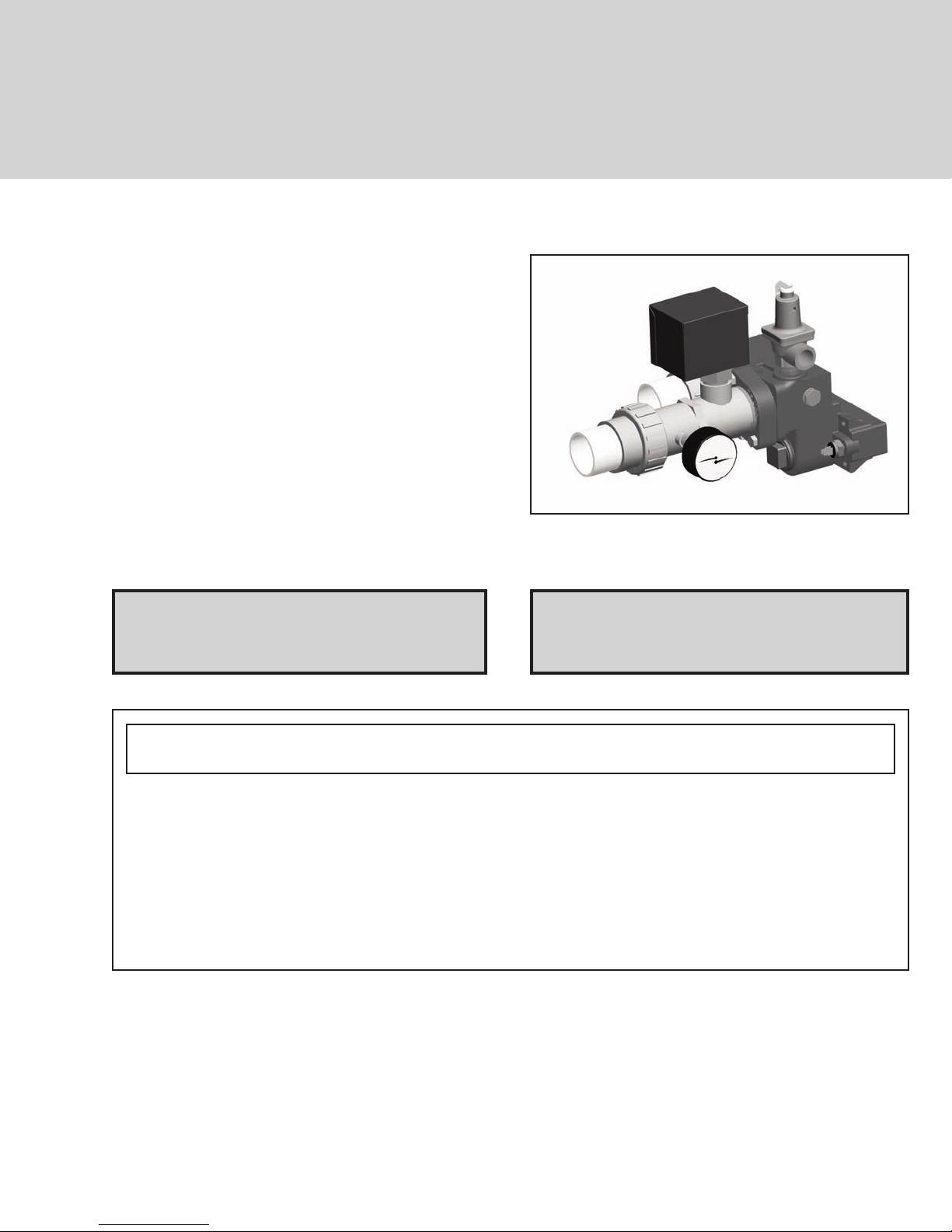
INSTALLATION INSTRUCTIONS
Flow Switch
&
Temperature/
Pressure
Gauge
For Atmospheric
Models C-R206AE-406AE
FOR YOUR SAFETY: Do not store or use gasoline or other flammable vapors and liquids or other
combustible materials in the vicinity of this or any other appliance. To do so may result in an explosion or fire.
WHAT TO DO IF YOU SMELL GAS:
• Do not try to light any appliance.
• Do not touch any electrical switch; do not use any phone in your building.
• Immediately call your gas supplier from a neighbor's phone. Follow the gas supplier's instructions.
• If you cannot reach your gas supplier, call the fire department.
Installation and service must be performed by a qualified installer, service agency or the gas supplier.
NOTE: Not for use with millivolt units.
Models C-R207AE-407AE
For Low NOx
Catalog No. 6000.59.1B Effective: 03-08-12 Replaces: 03-28-07 P/N 241309 Rev. 3
Page 2
NOTE: These instructions are intended primarily for
PLUMBING
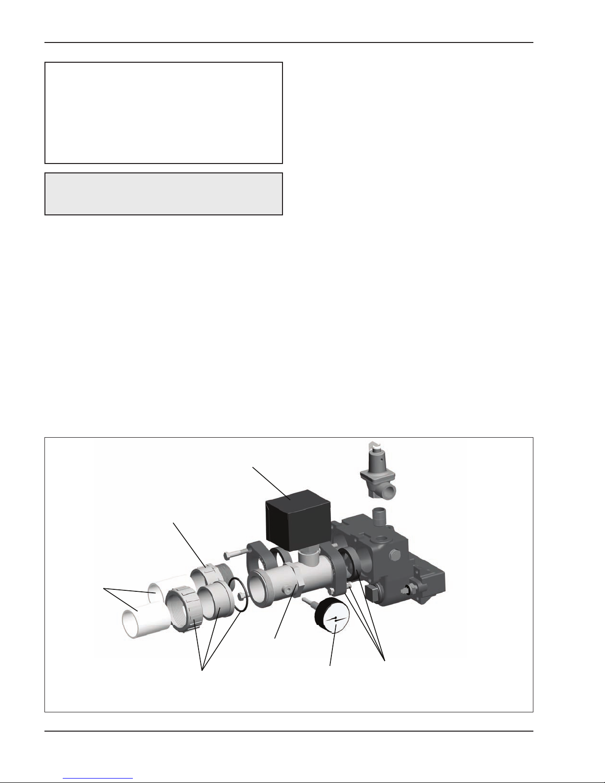
CPVC TAILPIECE
O-RING & RING NUT
(SUPPLIED)
CPVC MANIFOLD
(SUPPLIED)
T&P GAUGE
(SUPPLIED)
GASKETS, FLANGES
& BOLTS
(WITH ORIGINAL EQUIPMENT)
FLOW SWITCH COVER
(SUPPLIED)
MALE CPVC CONNECTOR
(WITH ORIGINAL EQUIPMENT)
use by qualified personnel specifically trained and
experienced in the installation of this type of heating
equipment and related system components.
Installation and service personnel must be licensed
in some states. Persons not qualified shall not
attempt to install this equipment nor attempt repairs
according to these instructions.
Before Starting
1) Turn off power to the heater at the circuit breaker.
2) Turn off gas supply.
3) Shut off the water supply to the heater.
DANGER - SHOCK HAZARD: Make sure electrical power to the heater is disconnected to avoid
potential serious injury or damage to components.
Kit Contents
Each kit includes:
(1) Temperature and Pressure gauge
(1) Pre-wired Flow Switch with outdoor cover
(2) Paddles
(1) Screw, #6-32 x 3/16
(1) 2” CPVC Tailpiece Connector
(1) 2” CPVC Manifold Adapter
(1) O-Ring
(2) Female spade terminals
(1) Ring nut
This kit is primarily intended for jurisdictions requiring
the addition of a flow switch and/or temperature and
pressure gauge on pool heaters.
4) Allow heater to cool down before attempting work.
INSTALLATION
1. Remove main front panel door and set aside.
2. Remove the front control panel screws (2 each
located at the ends of the panel). Lower front
panel to expose the main circuit board.
3. Remove transformer cover located on either the
upper right or left side.
4. Locate conduit opening above power conduit
opening on the waterside of the heater.
5. Locate the Inlet/Outlet header.
6. Install 2” flanges to header ports, if not already
installed.
Fig. 1: Flow Switch and Temperature and Pressure Gauge
2
Page 3

7. Locate and install the 2” CPVC manifold adapter
CONDUIT ENTRANCE
(Longer paddle)
(Shorter paddle)
Models Models
Paddle
Size
1.88” LG 1.8” LG
206, 207
266, 267
366, 367
406, 407
Paddle
ID
“F” “A”
CUT THE WHITE JUMPER LABELED “SPARE”
onto the Outlet side (see Fig.1). Careful not to strip
the threads on the manifold adapter.
8. Locate the flow switch, (2) paddles and (1) #6-32
screw.
9. Using a Phillips screw driver, install the correct
paddle size to the flow switch.
10. Install flow switch onto manifold adapter.
11. Be sure to verify the flow switch is positioned correctly to sense the proper direction of the water
flow, out of the heater.
a. The arrow on the flow switch indicates the
direction of flow.
12. Locate and install the flow switch cover, if not
already installed.
13. Locate and install the T&P gauge on the side of
the manifold adapter (see Fig.1).
14. Use the CPVC tailpiece, o-ring and ring nut to connect to your outlet plumbing.
15. Using the original equipment male CPVC connector, install your inlet plumbing.
16. Locate the pre-wired hard conduit off the flow
switch and route through the upper control panel
as indicated in Fig 2.
17. Cut the white “spare” jumper located on the back
of the circuit board in the upper control panel. See
Fig. 3.
18. Strip 1/4" of insulation from each end of the white
“spare” jumper cut in the previous step. Install and
crimp a female spade connector (supplied in kit)
on each stripped end.
a. Ensure the connectors being crimped are of
the proper size and shape to accept the connectors on the end of the wire harness.
b. Ensure the crimp is tight.
Fig 2: Transformer Box
Fig 3: Cutting the Jumper Wire
3
Page 4

19. Plug the connectors from the flow switch wire har-
www.raypak.com
FLOW SWITCH WIRES
CONNECTED TO “SPARE” JUMPER
ness into the connectors just installed on the white
“spare” jumper. See Fig. 4.
20. Reinstall the sheet metal transformer cover.
21. Close front control panel and reinstall the four
screws (two at each end).
22. Reinstall front main panel door onto the heater.
23. Turn water on to the heater and check for leaks.
a. If leaks are found, repair immediately.
24. Turn on gas to the heater.
25. Turn on power to the heater.
26. Cycle the heater a few times to verify flow switch
operation.
Fig 5: Completed Assembly
Fig 4: “Spare” Jumper Connections
Raypak, Inc., 2151 Eastman Avenue, Oxnard, CA 93030 (805) 278-5300 Fax (805) 278-5468
Litho in U.S.A.
4
 Loading...