

Page 1
731, 732, 733, 741, 742,
Certifi ed to:
ANSI Z21.97/CSA 2.41
for outdoor decorative
gas appliances
INSTALLATION &
OWNER’S MANUAL
Series:
743, 751, 752, 753
F13-042
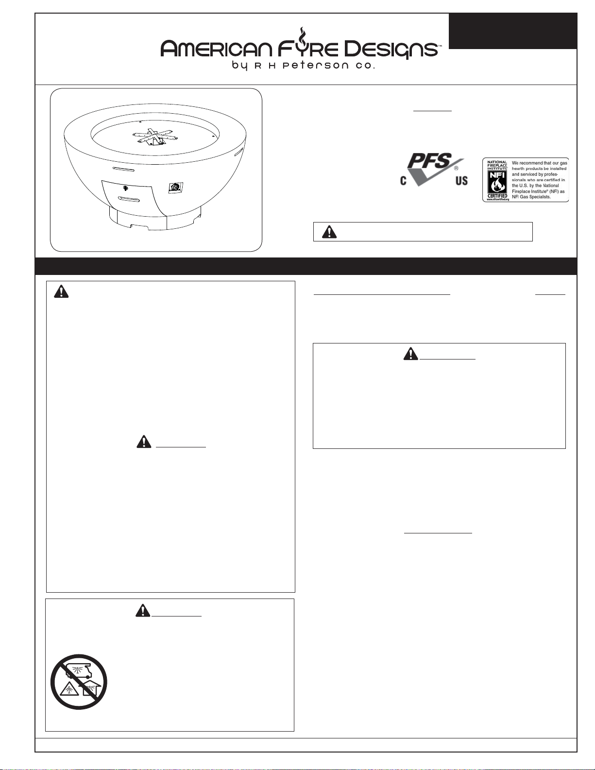
731
model shown
OUTDOOR FIRE BOWLS
WARNING: If the information in this manual
is not followed exactly, a fi re or explosion may
result causing property damage, personal
injury or loss of life.
- Do not store or use gasoline or other
fl ammable vapors and liquids in the vicinity
of this or any other appliance.
- A propane cylinder not connected for use
shall not be stored in the vicinity of this or
any other appliance.
DANGER
If you smell gas:
1. Shut off gas to the appliance.
2. Extinguish any open fl ame.
3. If odor continues, keep away from the
appliance and immediately call your gas
supplier or fi re department.
Installation and service must be performed by
an NFI Certifi ed or other qualifi ed professional
installer, service agency, or gas supplier.
DANGER
CARBON MONOXIDE HAZARD
This appliance can produce carbon
monoxide which has no odor.
Using it in an enclosed space can
kill you.
Never use this appliance in an
enclosed space such as a camper,
tent, car, or home.
WARNING: For Outdoor Use Only
INSTALLER & CONSUMER: These instructions MUST
be retained with this appliance for future reference.
Important: Read these instructions carefully
before starting installation of the unit.
WARNING
Improper installation, adjustment, alteration,
service, or maintenance can cause property
damage, personal injury, or loss of life. Read
the installation, operating and maintenance
instructions thoroughly before installing or
servicing this equipment.
This appliance is designed as an attended
appliance. Adults must be present when the
unit is operating. DO NOT leave this unit burning
when unattended. If this product is left burning
unattended, it may cause damage or serious injury.
IMPORTANT
For safe operation and proper performance of
this product and to comply with certification,
listings, and building code acceptances, use ONLY
Peterson AFD controls, parts, and accessories
that have been specifi cally listed or certifi ed for
use with this burner system. Use of other controls,
parts, or accessories is prohibited and will void
all warranties, certifi cations, listings, and building
code approvals, and may cause property damage,
personal injury, and loss of life.
CODE AND SUPPLY REQUIREMENTS:
The installation must conform with local codes and
ordinances, or, in the absence of local codes, with
the latest National Fuel Gas Code, ANSI Z223.1.
REV 0 - 1505180800
Robert H. Peterson Co. • 14724 East Proctor Avenue • City of Industry, CA 91746 Robert H. Peterson Co. • 14724 East Proctor Avenue • City of Industry, CA 91746 Robert H. Peterson Co. • 14724 East Proctor Avenue • City of Industry, CA 91746
1
L-H2-020
Page 2
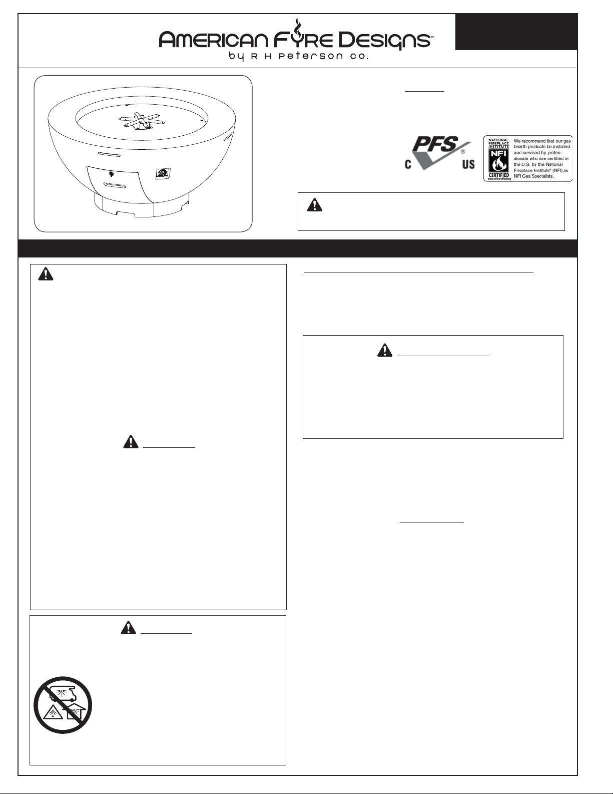
731
modèle
présenté
Certifi é à:
ANSI Z21.97/CSA 2.41
pour les appareils à gaz
décoratifs extérieurs
AVERTISSEMENT: Pour l'usage extérieur
PLEIN FEU BOLS
INSTALLATION ET
MODE D'EMPLOI
Series:
731, 732, 733, 741, 742,
743, 751, 752, 753
F13-042
seulement
AVERTISSEMENT: Si l'information en
ce manuel n'est pas suivie exactement, une
incendie ou une explosion peut résulter
entraînant des dégats matériels, le dommage
corporel ou des pertes humaines.
- Ne pas entreposer ni utiliser d'essence ou
d'autres vapeurs et liquides infl ammables
à proximité de cet appareil ou de tout autre.
- Une bouteille de propane non branchée ne
doit pas être entreposée à proximité de cet
ou tout autre appareil.
DANGER
Si vous sentez une odeur de gaz:
1. Coupez le gaz à l'appareil.
2. Éteindre toute fl amme nue.
3. Si l'odeur persiste, éloignez-vous de
l'appareil et appelez immédiatement votre
fournisseur de gaz ou les pompiers.
L'installation et le service doivent être
assurés par un NFI certifi é ou toute autre
installateur, agence de service, ou fournisseur
professionnelle qualifi ée de gaz.
DANGER
DANGER MONOXYDE DE CARBONE
Cet appareil peut produire du
monoxyde de carbone n'a pas d'odeur
qui.
Son utilisation dans un espace clos
peut vous tuer.
Ne jamais utiliser cet appareil dans
un espace clos comme une caravane,
tente, véhicule ou maison.
d'INSTALLATEUR; CONSOMMATEUR: Ces
instructions DOIVENT être maintenues avec cet appareil
pour la future référence.
Important: Lisez ces instructions soigneusement avant
de commencer l'installation de l'unité.
AVERTISSEMENT
L'installation, l'ajustement, le changement, le
service, ou l'entretien inexact peuvent causer des
dégats matériels, le dommage corporel, ou des
pertes humaines. Lisez l'installation, l'opération
et les instructions d'entretien complètement avant
d'installer ou entretenir cet équipement.
Cet appareil est conçu comme appareil occupé. Les
adultes doivent être présent quand l'unité fonctionne.
Ne laissez pas ce burning d'unité si sans surveillance.
Si ce produit est laissé sans surveillance brûlant, il peut
causer des dommages ou des dommages sérieux.
Pour l'exploitation sûre et l'exécution appropriée de
ce produit et pour se conformer à la certifi cation, aux
listes, et aux acceptations de codes du bâtiment,
commandes, pièces, et accessoires de Peterson
d'utilisation SEULEMENT qui ont été spécifi quement
énumérés ou certifi és pour l'usage avec ce système de
brûleur. L'utilisation d'autres commandes, pièces, ou
accessoires est interdite et videra toutes les garanties,
certifi cations, listes, et approbations de codes du
bâtiment, et peut causer des dégats matériels, le
dommage corporel, et des pertes humaines.
CONDITIONS DE CODE ET D'APPROVISIONNEMENT:
L'installation doit se conformer aux codes locaux et
aux ordonnances, ou, en l'absence des codes locaux,
au plus défunt code national de gaz de carburant, la
norme ANSI Z223.1.
IMPORTANT
REV 0 - 1505180800
2
L-H2-020
Page 3

TABLE OF CONTENTS
GETTING STARTED
PRE-INSTALLATION AND PREPARATION SAFETY
GUIDELINES ................................................................4
INSTALLATION SAFETY GUIDELINES .......................5
OPERATING THE UNIT SAFELY AND CORRECTLY ...5
SAFE USE & MAINTENANCE OF PROPANE GAS
CYLINDERS ..................................................................7
SPECIFICA TIONS AND DIMENSIONS ..........................8
PRIMARY MEDIA OPTIONS .......................................9
SECONDARY MEDIA OPTIONS ..................................9
MINIMUM CLEARANCES TO COMBUSTIBLES ....... 10
TOOLS REQUIRED .................................................... 10
PARTS LIST .................................................................11
INSTALLATION
IMPORTANT SAFETY INFORMATION ...................... 16
FIRE BOWL INSTALLATION - COMMON ................. 16
BEFORE YOU BEGIN ............................................. 16
LOCATION .......................................................... 16
FIRE BOWL INSTALLATION - BOWL ONLY ............. 17
GAS SUPPLY SETUP (if applicable) .......................... 17
PLACE UNIT......................................................... 17
REMOVE DOOR (if applicable) ................................ 17
CONNECT GAS SUPPLY ......................................... 18
LEAK TEST ........................................................... 19
INSTALL REFRACTORY PANEL / BURNER ................ 19
REPLACE STORAGE DOOR (if applicable)................. 19
FIRE BOWL INSTALLATION - BOWL AND PEDESTAL
................................................................................... 20
PLACE PEDESTAL ................................................. 20
MOUNT PEDESTAL ............................................... 20
PLACE BOWL ....................................................... 20
MOUNT BOWL ...................................................... 21
CONNECT GAS SUPPLY ......................................... 22
LEAK TEST ........................................................... 23
CLOSE STORAGE DOOR ........................................ 23
INSTALL REFRACTORY PANEL / BURNER ................ 23
DECORATIVE MEDIA PLACEMENT .........................24
LAVA MEDIA ........................................................ 24
VOLCANIC STONE ................................................ 24
LOG SETS ............................................................ 24
GLASS MEDIA ...................................................... 25
ADDITIONAL SECONDARY OPTIONS ..................... 25
OPTIONAL ACCESSORIES ........................................ 26
OPTIONAL FABRIC COVER .................................... 26
USE, CARE, & SERVICE
LIGHTING INSTRUCTIONS - CONTROL KNOB
MODELS ................................................................... 27
FOR YOUR SAFETY, READ BEFORE LIGHTING ....... 27
TO SHUT OFF GAS TO THE APPLIANCE .................27
LIGHTING INSTRUCTIONS - KEY VALVE MODELS
.................................................................................. 29
FOR YOUR SAFETY, READ BEFORE LIGHTING ....... 29
TO SHUT OFF GAS TO THE APPLIANCE .................29
SER VICING AND CLEANING ................................... 31
ANNUAL CLEAN / INSPECTION GUIDELINES.......... 31
CONCRETE CARE ................................................ 32
FUEL CONVERSION KITS ..................................... 32
TROUBLESHOOTING ............................................... 33
WARRANTY ............................................................. 34
IMPORTANT SAFETY INFORMATION
Congratulations on your purchase of an American Fyre Designs outdoor gas fi re bowl. Made with pride in America,
your new fi re bowl complies with national safety standards and when installed per these instructions and used
as intended it will provide warmth and comfort to your outdoor area for many years.
Prior to installation and operation ensure that all specifi cations, dimensions, and minimum clearances
stated in this manual are observed. You must read all warnings and safety information, and understand
all of the information in this manual. All installation requirements must be observed and met.
REV 0 - 1505180800
3
L-H2-020
Page 4
PRE-INSTALLATION AND PREPARATION SAFETY GUIDELINES
A. A shut-off valve (not included) in the gas line is required. It provides for safety when the unit is not in use
and for convenient maintenance and repair. It can be installed remotely (within 6 feet of unit) or at the end of
the gas supply stub. Use a pipe joint compound resistant to all gasses on all male fi ttings except fl are fi ttings.
B. Before installing this unit, check the MINIMUM CLEARANCE TO COMBUSTIBLES section to ensure that the
surrounding area is properly sized for the installation.
C. The unit is for outdoor use only. DO NOT install or use this appliance inside a building, garage, or any other
enclosed area, including recreational vehicles and/or boats. THIS UNIT MUST BE INSTALLED IN SUCH A
MANNER THAT ALL VENT OPENINGS ON THE UNIT REMAIN CLEAR AND FREE OF ALL OBSTRUCTIONS
AT ALL TIMES AND DURING ALL WEATHER CONDITIONS.
D. SOLID FUEL MUST NOT BE BURNED in the unit.
E. CHECK GAS TYPE ( natural gas or propane): The gas supply you intend to use may not be the same as that
stated on the unit rating plate as purchased. If the gas supply is different, convert the unit to the gas type
you intend to use (IF PERMITTED). See the FUEL CONVERSION KIT section and contact the dealer for
assistance.
F. FOR NATURAL GAS: The minimum inlet gas-supply pressure for purposes of input adjustment is 5" water
column (w.c.), and the maximum inlet gas-supply pressure is 10.5 " w.c.
FOR PROPANE GAS: The minimum inlet gas-supply pressure for purposes of input adjustment is 11" w.c., and
the maximum inlet gas-supply pressure is 13" w.c. DO NOT INSTALL THIS UNIT IF MINIMUM PRESSURE
IS NOT AVAILABLE OR IF MAXIMUM PRESSURE IS EXCEEDED.
G. The gas piping system must be sized to provide minimum inlet pressure at the maximum fl ow rate
(BTU/hr). Undue pressure loss will occur if the pipe is too small, or the run is too long. Gas supply pipe must
be 1/2" minimum interior diameter. If the gas line is longer than 20', a larger diameter line may be necessary.
Refer to the NFPA 54 guidelines for further details.
H. For installations at elevations above 2,000 ft., contact your local dealer or gas supplier before installing. Input
ratings should be reduced approximately 4% for each 1,000 ft. above sea level. Refer to the National Fuel Gas
Code.
I. The unit and its individual shut-off valve must be disconnected from the gas-supply piping system during any
pressure testing of that system at test pressures in excess of 1/2 psi (3.5 kPa). This is accomplished by closing
the gas-supply line valve. The unit must be isolated from the gas-supply piping system by closing its individual
manual shut-off valve during any pressure testing of the gas-supply piping system at test pressures equal to
or less than 1/2 psi (3.5 kPa).
J. When an appliance is for connection to a fi xed piping system, the installation must conform with local codes,
or in the absence of local codes with the National Fuel Gas Code, ANSI Z223.1/NFPA 54; International Fuel
Gas Code, Natural Gas and Propane Installation Code, CSA B149.1; or Propane Storage and Handling Code,
B149.2, as applicable.
K. INSTALLER NOTE: This unit should be installed so that it can be removed if service is required.
L. GAS-SUPPLY PLUMBING REQUIREMENTS
Apply only joint compounds that are resistant to all gasses on all male pipe fi ttings. Make sure to tighten every
joint securely. Do not use pipe joint compound to connect fl are fi ttings. Bring the gas-supply pipe up from
beneath the enclosure near its center (if applicable).
CAUTION: Installation and maintenance must be done by an NFI Certifi ed or other qualifi ed professional service
technician. Installer, read these instructions before installing this product. Be sure you understand all
safety precautions and warnings contained in this manual.
4
Page 5
INSTALLATION SAFETY GUIDELINES
A. Carefully inspect for shipping damage. If any parts are damaged, contact your dealer.
B. Installation and repair should be done by a qualifi ed professional service technician. The appliance should
be inspected before use and at least annually by a qualifi ed service person. More frequent cleaning may be
required as necessary. It is imperative that control compartment, burners and circulating air passageways of
the appliance are kept clean.
C. WEAR GLOVES AND USE EXTREME CAUTION WHENEVER INSTALLING AND HANDLING THIS
PRODUCT AND ITS ACCESSORIES AS CERTAIN COMPONENTS HAVE SHARP EDGES THAT CAN
CAUSE PERSONAL INJURY.
D. Correct installation and proper placement of the unit and decorative media is crucial to the safe performance
of the unit. See installation instructions for further information.
E. FIRE BOWL MODELS: DO NOT install the unit under any overhead combustible materials that are less than
8 feet above the top of the unit.
FIRE BOWL AND PEDESTAL MODELS: DO NOT install the unit under any overhead combustible materials.
F. Ensure that the unit is installed on a hard and level surface.
G. Ensure that the unit is installed in such a manner that all vent openings on the unit remain clear and free of all
obstructions at all times and during all weather conditions.
H. Due to high temperatures, the unit must be located out of traffi c areas and away from combustibles.
OPERATING THE UNIT SAFELY AND CORRECTLY
A. This product is a decorative gas appliance. It is not a cooking appliance.
B. SOLID FUEL MUST NOT BE BURNED in the unit.
C. When shutting the unit down—be sure to TURN THE CONTROL VALVE FULLY OFF.
D. Children MUST be supervised when they are in the area of this appliance.
E. DO NOT sit or place any part of the body, clothing, or other fl ammable materials on or near the unit surround.
Children and adults should be alerted to the hazard of high surface temperatures and should stay away to
avoid burns or clothing ignition. DO NOT lean over the unit when lighting or when in use.
F. Every time you use the unit, make sure that:
1. The area around the unit is clear and free from combustible materials, gasoline and other fl ammable vapors
and liquids.
2. There is no blockage of the airfl ow through the vent openings located on the unit.
G. WARNING: HOT WHILE IN OPERATION AND FOLLOWING OPERATION. Serious injury can occur! DO NOT
throw trash, paper, or other fl ammable materials onto the unit. DO NOT leave in operation when unattended.
WARNING: DO NOT operate this unit in the rain.
WARNING: DO NOT operate this unit in high-wind conditions. Operating in high-wind conditions may
expose your unit to direct fl ame, which will result in cracking and discoloration to the fi nish.
H. DO NOT continue using if you smell unusual odors, or have headaches, nausea, or dizziness.
I. DO NOT store any combustible materials, gasoline, and any other fl ammable vapors/liquids in the vicinity of
the unit. Provide adequate clearance for servicing and operation.
J. Matches, paper, garbage, or any other material must not be thrown onto the unit or into the fl ame.
K. DO NOT use the unit if any part of it has been underwater. Immediately call a qualifi ed professional service
technician to inspect the unit and to replace any part of the control system and any gas control that has been
underwater.
5
Page 6

U
L
UTILISATION SÛRE ET ENTRETIEN DES CYLINDRES DE GAZ DE PROPANE
IMPORTANT POUR VOTRE SÛRETÉ
LISEZ ET SUIVEZ TOUS LES AVERTISSEMENTS ÉQUIPÉS DE VOTRE CYLINDRE DE GAZ DE PROPANE.
En actionnant cet appareil avec un cylindre de gaz de propane ON DOIT observer ces instructions et avertissements.
LE MANQUE DE FAIRE AINSI PEUT AVOIR COMME CONSÉQUENCE UNE INCENDIE OU UNE EXPLOSION SÉRIEUSE.
CYLINDRE ET CONDITIONS ET
CARACTÉRISTIQUES DE CONNECTEUR
a. Des cylindres et les valves de gaz de propane doivent être
maintenus en bon état et doivent être remplacés s’il y a
des dommages évidents au cylindre ou à la valve.
b. Ce gril, une fois utilisé avec un cylindre, devrait être relié à
un gallon de la norme 5 (20lb.) cylindre de gaz de propane
équipé d’un OPD (remplissez au-dessus du niveau le
dispositif d’empêchement). L’OPD a été exigé sur tous les
cylindres vendus depuis octobre 1.1998 pour empêcher le
remplissage excessif.
c. Les dimensions de cylindre devraient être approximativement
12"(30.5cm) de diamètre et 18" (45.7cm) hauts. Des
cylindres doivent être construits et marqués selon les
caractéristiques pour des cylindres de gaz de propane du
département des ETATS-UNIS du transport (D.O.T.) ou
le niveau national du Canada, du CAN/CSA-B339, des
cylindres, des sphères et des tubes pour le transport des
marchandises dangereuses.
d. Le cylindre doit inclure un collier pour protéger la valve
de cylindre et le circuit d’alimentation de cylindre doit être
assuré le retrait de vapeur.
e. Le montage du régulateur de pression et le fl exible (Fig. 6-1)
e. Le régulateur de pression et l’ensemble de tuyau utilisé
fourni avec cet appareil au gaz en plein air (modèles au
doivent assortir les spécifi cations pour le type I par ANSI
propane seulement) doit être utilisé. Assemblées d'origine et
Z 21.58-2005/CGA 1.6-2005 (voir la fi gue. 6-1).
régulateur de pression et le tuyau de remplacement doivent
être ceux spécifi és par le fabricant pour le raccordement d'un
dispositif de cylindre de liaison identifi ée comme de type I par
le 21.58-2005/CGA ANSI Z 1.6 à 2005 (voir liste des pièces
pour les informations de commande).
f. La valve de cylindre de gaz de propane doit être équipée
d’un dispositif d’accouplement de raccordement de
cylindre, décrit comme type I dans la norme défi nie dans le
e. de paragraphe ci-dessus. Ce dispositif est généralement
décrit comme coupleur rapide de fi l de point culminant.
g. Si votre cylindre de gaz de propane vient avec une prise
de la poussière, placez le bouchon anti-poussière sur la
sortie de valve de cylindre toutes les fois que le cylindre
n’est pas en service.
OPÉRATION DE COUPLEUR RAPIDE
Pour relier le regulator/hose à l’ajustage de précision de
valve de cylindre de gaz de propane: Serrez l’écrou de main
sur le régulateur au-dessus de l’ajustage de précision de fi l
de point culminant sur la valve de cylindre. Tournez l’écrou de
main dans le sens des aiguilles d’une montre pour engager les
fi ls et pour serrer jusqu’à ce que douillettement. L’utilisation des
pinces ou de la clé ne devrait pas être nécessaire. Seulement
le propane marqué par cylindres doit être employé.
Pour débrancher: Tournez l’écrou de main dans le sens
contraire des aiguilles d’une montre jusqu’à isolé (fi g. 6-1).
Important: Avant d’employer le gril, et ensuite chaque
fois que le cylindre est enlevé et rattaché,
examinez tous les raccordements pour déceler
les fuites. Arrêtez les valves de gril et ouvrez
la valve principale de cylindre, puis vérifi ez
les raccordements avec de l’eau savonneux.
Réparez toutes les fuites avant d’allumer le gril.
ATTENTION: Tournez toujours la valve principale de cylindre
de propane au loin après chaque utilisation,
et avant de déplacer le gril et le cylindre, ou
débrancher l’accouplement. Cette valve doit
rester fermée et le cylindre a débranché alors
que l’appareil n’est pas en service, quoique
l’écoulement de gaz soit arrêté par un dispositif
de sûreté quand le coupleur est débranché.
Inspectez soigneusement l’ensemble de tuyau chaque fois
avant que le gaz soit allumé. Un tuyau fi ssuré ou effi loché doit
être immédiatement remplacé.
Si l'appareil est stocké à l'intérieur, le cylindre doit être disconnected
et a enlevé. Des cylindres Disconnected doivent être stockés
dehors, hors de la portée des enfants, avec les prises de valve
fi letées étroitement installées, et ne doivent pas être stockés dans
un bâtiment, le garage, ou n'importe quel autre secteur inclus.
POUR VOTRE SÛRETÉ
a. Ne stockez pas un cylindre de gaz disponible de propane
dessous ou ne vous approchez pas de cet appareil.
b. Ne remplissez jamais cylindre au delà de 80 pour cent de
plein.
c. SI L’INFORMATION DANS “A” ET “B” N’EST PAS SUIVIE
EXACTEMENT, UN FEU CAUSANT LA MORT OU DES
DOMMAGES SÉRIEUX PEUT SE PRODUIRE.
Fig. 6-1 type coupleur rapide de fi l de point culminant d’I
Volant de commande
QCC
Type 1
Valve
Valve
de
décompression
1
Ajustage de précision
en laiton de fi l de
point culminant
4
Indicateur
de niveau
de liquide
(facultatif)
3
2
Écrou de main avec le
fi l de point culminant.
Régulateur
Passage
Tuy au
6
Page 7
U
L
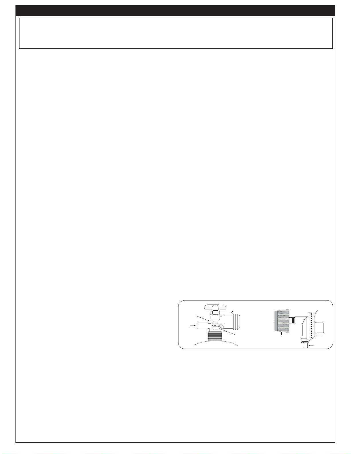
SAFE USE & MAINTENANCE OF PROPANE GAS CYLINDERS
IMPORTANT FOR YOUR SAFETY
READ AND FOLLOW ALL WARNINGS PROVIDED WITH THE PROPANE-GAS CYLINDER.
When operating this appliance with a propane-gas cylinder, these instructions and warnings MUST be observed.
FAILURE TO DO SO MAY RESULT IN A SERIOUS FIRE OR EXPLOSION.
CYLINDER/CONNECTOR REQUIREMENTS
a. Propane-gas cylinders, valves, and hoses must be
maintained in good condition and must be replaced if
there is visible damage to either the cylinder or valve. If the
hose is cut or shows excessive abrasion or wear, it must
be replaced before using the gas appliance (see e.).
b. This unit, when used with a cylinder, should be connected
to a standard 5-gallon (20 lb.) propane-gas cylinder
equipped with an OPD (Overfi ll Prevention Device).
The OPD has been required on all cylinders sold since
October 1,1998, to prevent overfi lling.
c. Cylinder dimensions should be approximately 12" (30.5
cm) in diameter and 18" (45.7 cm) high. Cylinders must
be constructed and marked in accordance with the
Specifi cations for Propane Gas Cylinders of the U.S.
Department of Transportation (D.O.T.) or the National
Standard of Canada, CAN/CSA-B339, Cylinders,
Spheres, and Tubes for Transportation of Dangerous
Goods.
d. The cylinder used must include a collar to protect the
cylinder valve, and the cylinder supply system must be
arranged for vapor withdrawal.
e. The pressure regulator and hose assembly used must
e. The pressure regulator and hose assembly (Fig. 7-1)
match the specifi cation for Type I by ANSI Z 21.58-2005/
supplied with this outdoor gas appliance (L.P. models
CGA 1.6-2005 (see Fig. 7-1).
only) must be used. Original and replacement pressure
regulator and hose assemblies must be those specifi ed
by the manufacturer for connection with a cylinder
connecting device identifi ed as Type I by the ANSI Z
21.58-2005/CGA 1.6-2005 (see PARTS LIST for ordering
information).
f. The propane-gas cylinder valve must be equipped with a
cylinder connection coupling device, described as Type I
in the standard defi ned in paragraph e. above. This device
is commonly described as an Acme thread quick coupler.
g. If the propane-gas cylinder comes with a dust plug, place
the dust cap on the cylinder valve outlet whenever the
cylinder is not in use.
QUICK COUPLER OPERATION
To connect the regulator/hose assembly to the propanegas cylinder valve fi tting: Press the hand nut on the regulator
over the Acme thread fi tting on the cylinder valve. Turn the hand
nut clockwise to engage the threads and tighten until snug.
The use of pliers or a wrench should not be necessary. Only
cylinders marked “propane” may be used.
To disconnect: Turn the hand nut counterclockwise until
detached (Fig. 7-1).
Important: Before using the unit, and after each time the
cylinder is removed and reattached, check
the hose for wear (see a.) and check all
connections for leaks. Turn off the unit valves
and open the main cylinder valve, then check
connections with soapy water. Repair any
leaks before lighting the unit.
CAUTION: Always turn the propane cylinder main valve
off after each use, and before moving the unit
and cylinder or disconnecting the coupling.
This valve must remain closed and the
cylinder disconnected while the appliance
is not in use, even though the gas fl ow is
stopped by a safety feature when the coupler
is disconnected.
Carefully inspect the hose assembly each time before the
gas is turned on. A cracked or frayed hose must be replaced
immediately.
If the appliance is stored indoors, the cylinder must be
disconnected and removed. Disconnected
cylinders must be
stored outdoors, out of the reach of children, with threaded
valve plugs tightly installed, and must not be stored in a
building, garage, or any other enclosed area.
FOR YOUR SAFETY
a. DO NOT store a spare propane-gas cylinder under or
near this appliance.
b. NEVER fi ll the cylinder beyond 80-percent full.
c. IF THE INFORMATION IN a. AND b. IS NOT FOLLOWED
EXACTLY, A FIRE CAUSING DEATH OR SERIOUS
INJURY MAY OCCUR.
Fig. 7-1 Type I Acme thread quick coupler
QCC
Type 1
valve
Pressure
relief
valve
Hand wheel
Brass Acme
thread fi tting
Liquid level
indicator
(optional)
Hand nut with Acme
thread
Regulator
Vent
Hose
7
Page 8
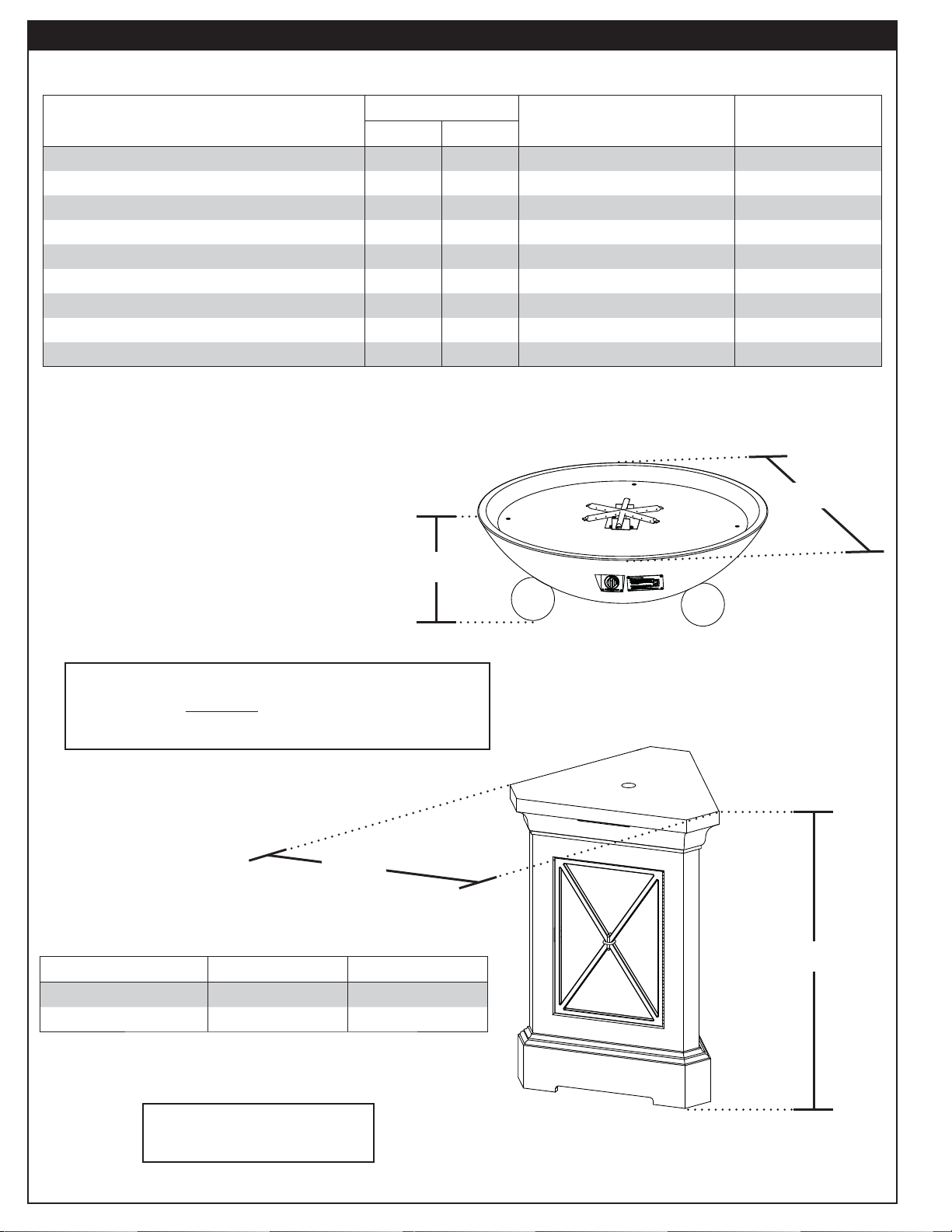
SPECIFICATIONS AND DIMENSIONS
Style
Dimensions Weight / Pieces
Nat. L.P.
BTUs
48" Fire Bowl (731) 60,000 50,000 22" h x 48" exterior dia. 250 lbs / 2 pcs
36" Fire Bowl (732) 60,000 50,000 16" h x 36" exterior dia. 154 lbs / 2 pcs
32" Fire Bowl (733) 60,000 50,000 16" h x 32" exterior dia. 109 lbs / 2 pcs
48" Versailles Fire Bowl w/Ball Feet (741) 60,000 50,000 15" h x 48" exterior dia. 220 lbs / 2 pcs
40" Versailles Fire Bowl w/Ball Feet (742) 60,000 50,000 14" h x 40" exterior dia. 170 lbs / 2 pcs
32" Versailles Fire Bowl w/Ball Feet (743) 60,000 50,000 11 1/4" h x 32" exterior dia. 104 lbs / 2 pcs
48" Marseille Fire Bowl (751) 60,000 50,000 10 1/2" h x 48" exterior dia. 195 lbs / 2 pcs
40" Marseille Fire Bowl (752) 60,000 50,000 11" h x 40" exterior dia. 150 lbs / 2 pcs
32" Marseille Fire Bowl (753) 60,000 50,000 81/2" h x 32" exterior dia. 90 lbs / 2 pcs
Table 1 - Overall Fire Bowl Dimensions
Exterior Dia.
Height
The following fi re bowl models are designed for
use with the optional pedestals listed below:
741, 742, 743, 751, 752, 753
Width
Style Dimensions Weight / Pieces
44" Pedestal (8644) 44" h x 28" w 238 lbs / 1 pc
54" Pedestal (8654) 54" h x 28" w 242 lbs / 1 pc
742
model shown
Height
Table 2 - Overall Pedestal Dimensions
Optional pedestals are
purchased separately
8644
model shown
8
Page 9
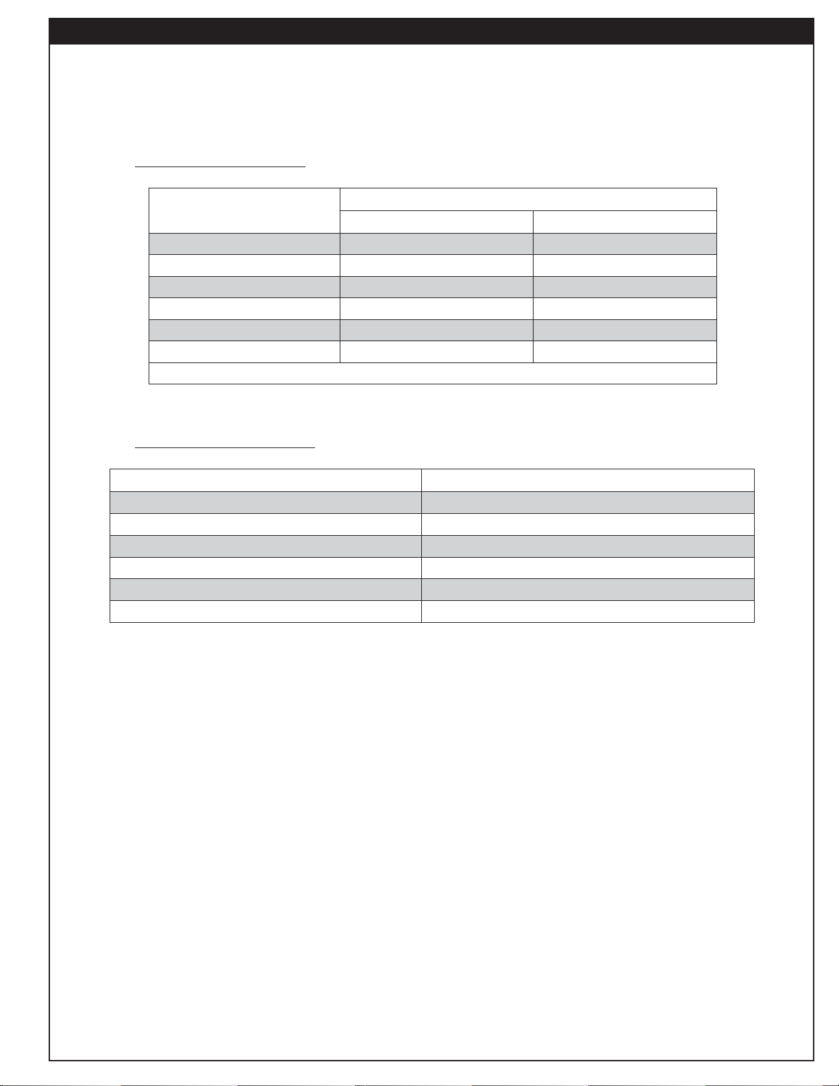
SPECIFICATIONS AND DIMENSIONS (cont.)
Follow the recommendations below for decorative media options and amounts. All decorative media options are
purchased separately. Contact your local American Fyre Designs dealer when ordering.
PRIMARY MEDIA OPTIONS
When using lava media:
Style
Recommended Amount of Lava Media
Lava Granules Option Lava Coals Option
731 45 lbs 40 lbs
732 40 lbs 35 lbs
733 30 lbs 30 lbs
741, 751 60 lbs 60 lbs
742, 752 40 lbs 40 lbs
743, 753 30 lbs 30 lbs
When using volcanic stone in addition to above mentioned lava media, use VS-25 (25 lbs).
Table 3 - Lava Recommendations
When using glass media:
Style Recommended Amount of Glass / Gems
731 90 lbs
732 80 lbs
733 55 lbs
741, 751 130 lbs
742, 752 90 lbs
743, 753 60 lbs
Table 4 - Glass Recommendations
SECONDARY MEDIA OPTIONS
Secondary options such as logs / volcanic stone / river stone / geo shapes / glass nuggets (purchased separately)
may also be placed on top of the lava or glass media.
9
Page 10
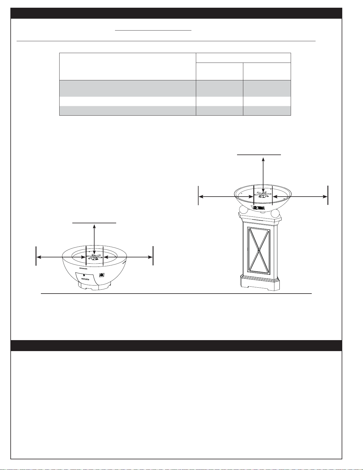
MINIMUM CLEARANCES TO COMBUSTIBLES
The dimensions shown below are MINIMUM CLEARANCES to maintain when you install the unit.
ALL CLEARANCES AND INFORMATION STATED HERE MUST BE MAINTAINED AND FOLLOWED.
Dimension
Description
Side clearance
(from burner edge to combustible construction)
Clearance above unit 8 ft
Clearance below unit 0" 0"
Table 5 - Minimum Clearances to Combustibles
Fire bowl
Fire bowl and
only
3 ft 3 ft
Pedestal
Not permitted
3 ft
side clearance
(burner edge
to combustible
construction)
8 ft
3 ft
side clearance
(burner edge
to combustible
construction)
3 ft
side clearance
(burner edge
to combustible
construction)
Floor must be a hard, level surface.
Combustible materials permitted.
Nothing above unit.
3 ft
side clearance
(burner edge
to combustible
construction)
TOOLS REQUIRED
The following are the minimum tools required for the installation of your unit. Additional tools may be required
for your individual installation.
• 2 man (or more) crew recommended
• appropriate tools for gas supply
install
• cordless drill
10
• Phillips screwdriver
• adjustable wrench
(or equivalent)
• drill drivers
Page 11
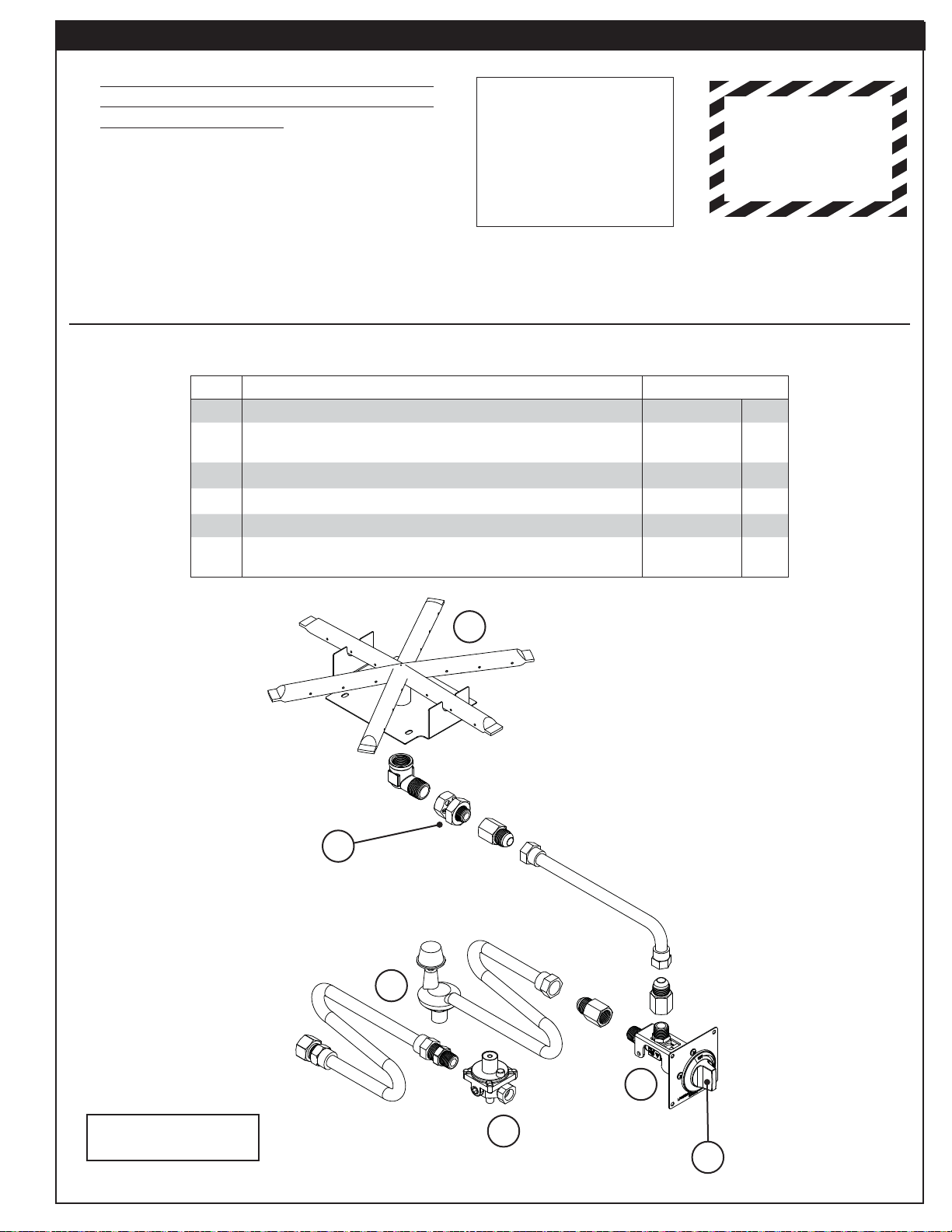
PARTS LIST
• In addition to the appropriate Common
Replacement Parts List, reference the
Identifi cation Parts Lists.
• Your unit is packaged onto 1 pallet.
• Decorative media is purchased and packaged
separately. Various styles are available.
• Decorative media and replacement parts can
be ordered from your local American Fyre
Designs dealer.
• Select models are illustrated
(your model may vary)
COMMON REPLACEMENT PARTS LIST - V2 MODELS (731 model)
Item Description Part No. Qty.
1. 12" star burner, only OBS-12 1
2.
Orifi ce (Nat.)
or
Orifi ce (L.P.)
3. Control valve w/ knob assembly SV-61 1
4. Control knob (only) KNOBS4 1
5. Convertible regulator (Nat. only) PR-1 1
6.
Flex connector (Nat. only)
or
L.P. regulator and hose assembly (L.P. only)
IMPORTANT
Remove all packing
material (including
any protective
coatings) and
discard prior to use.
AB-2-24
AM-2-44
3035
5110-07
SOME COMPONENTS
ARE HEAVY
HANDLE WITH CARE
1
1
1
1
Confi guration shown
may slightly vary from
that of your model
1
2
6
This page is for 731
models only
3
5
4
11
Page 12

PARTS LIST (cont.)
COMMON REPLACEMENT PARTS LIST - K2 MODELS (731 model)
Item Description Part No. Qty.
1. 12" star burner, only OBS-12 1
2.
Orifi ce (Nat.)
or
Orifi ce (L.P.)
3. Key valve w/ key assembly AV-32 1
4. Key (only) VK-1 1
5. Convertible regulator (Nat. only) PR-4 1
6.
Flex connector (Nat. only)
or
L.P. regulator and hose assembly (L.P. only)
1
AB-2-26
AM-2-44
3035
5110-07
1
1
1
1
Confi guration shown
may slightly vary from
that of your model
2
6
3
5
4
This page is for 731
models only
12
Page 13

PARTS LIST (cont.)
COMMON REPLACEMENT PARTS LIST - V2 MODELS
(732, 733, 741, 742, 743, 751, 752, 753 models)
Item Description Part No. Qty.
1. 12" star burner, only OBS-12 1
2.
Orifi ce (Nat.)
or
Orifi ce (L.P.)
3.
Control valve w/ knob assembly (741, 742, 743, 751, 752, 753)
or
Control valve w/ knob assembly (732, 733)
4. Control knob (only) KNOBS4 1
5. Convertible regulator PR-4 1
6.
Flex connector (741, 742, 743, 751, 752, 753)
or
Flex connector (732, 733)
AB-2-24
AM-2-44
SV-65
SV-62
3036
3035
1
1
1
1
1
1
Confi guration shown
may slightly vary from
that of your model
1
2
6
13
5
3
4
Page 14

PARTS LIST (cont.)
COMMON REPLACEMENT PARTS LIST - K2 MODELS
(732, 733, 741, 742, 743, 751, 752, 753 models)
Item Description Part No. Qty.
1. 12" star burner, only OBS-12 1
2.
Orifi ce (Nat.)
or
Orifi ce (L.P.)
3.
Key valve w/ key assembly (741, 742, 743, 751, 752, 753)
or
Key valve w/ key assembly (732, 733)
4. Key (only) VK-1 1
5. Convertible regulator PR-4 1
6.
Flex connector (741, 742, 743, 751, 752, 753)
or
Flex connector (732, 733)
AB-2-26
AM-2-44
AV-32
AV-33
3036
3035
1
1
1
1
1
1
Confi guration shown
may slightly vary from
that of your model
1
2
6
5
3
4
14
Page 15

PARTS LIST (cont.)
IDENTIFICATION PARTS LIST (Bowl)
Item Description Qty.
1. Base 1
Refractory panel insert 1
2.
Door (731 models only) * 1
3.
1
4.
* not shown
1
/4" x 13/4" Concrete Phillips screw * 4
2
742
model shown
IDENTIFICATION PARTS LIST (Pedestal - if equipped)
Item Description Qty.
1. Base 1
Door 1
2.
Pipe extension (for gas supply) * 1
3.
Mounting hardware kit *
4.
* Not shown
†
kit contains: (1) conduit mount, (1) conduit cover, (1) nut, (1) washer
†
1
1
2
8644
model shown
15
Page 16

IMPORTANT SAFETY INFORMATION
BE CAREFUL
If not installed and used correctly per these instructions,
this product can cause serious injury.
CAUTION: Installation and maintenance must be done by an NFI Certifi ed or other qualifi ed professional service
technician. Read these instructions before installing this unit. Be sure you understand all safety
precautions and warnings contained in this manual.
A. FOR OUTDOOR USE ONLY.
B. When shutting the unit down—be sure to TURN THE CONTROL VALVE FULLY OFF.
C. WARNING: CARBON MONOXIDE POISONING MAY LEAD TO DEATH. DO NOT MODIFY THIS UNIT OR
ITS CONTROLS, EXCEPT AS PROVIDED FOR IN THIS MANUAL. Any other change may be dangerous.
Improper installation or use of the unit can cause serious injury or death from fi re, burns, explosions, or
carbon monoxide poisoning.
D. Check state and local codes to determine if the unit is permitted in your locality before installation.
E. The manual valve allows for an adjustable fl ame height. THESE SETTINGS MUST ALWAYS BE HIGH ENOUGH
FOR THE FLAME TO BE CLEARLY VISIBLE. WHEN LIGHTING THE UNIT, ALWAYS LIGHT ON HIGH.
FIRE BOWL INSTALLATION - COMMON
BEFORE YOU BEGIN
Important: Prior to installation ensure that all specifi cations, dimensions, and minimum clearances stated
in this manual are observed. You must read all warnings and safety information, and understand
all of the information in this manual. All installation requirements must be observed and met.
WARNING: Failure to position the parts in accordance with these diagrams or failure to use only parts specifi cally
approved with this appliance may result in property damage or personal injury.
• Confi rm the installation site accommodates the unit per the requirements in this manual.
• Be sure the gas supply (propane or natural) is turned off at its source.
• Remove all packing material (including any protective coatings) and discard prior to installation.
LOCATION
While following all requirements and safety information in this manual (see MINIMUM CLEARANCES TO
COMBUSTIBLES section); determine and prepare the location of the unit (a hard and level surface).
Note: For fi re bowls, a combustible surface is permitted.
Important: The gas supply must be considered when determining the location of the unit. See GAS
SUPPLY SETUP section for details (if applicable).
ASSEMBLY REQUIRES TWO OR MORE PEOPLE.
EXERCISE EXTREME CARE DURING ASSEMBLY AND INSTALLATION.
16
Page 17

FIRE BOWL INSTALLATION - COMMON (cont.)
GAS SUPPLY SETUP (if applicable)
For Natural or Household Propane Gas Supply:
The gas supply is to be brought up from beneath the unit near its center. Your individual installation may vary.
Observe all local codes.
1. Route the gas supply into the area that the unit will rest over.
Note: The gas supply or another fl ex can also be routed through the side of the unit (through a ventilation
opening at the fl oor).
Important: Locate the gas supply line out of pathways where people may trip over it or in areas where
the line may way be subject to accidental damage (if applicable).
2. A shut-off valve (not included) in the gas line is required. It can be installed remotely (within 6 feet of
unit) or at the end of the gas supply stub. Use a pipe joint compound resistant to all gasses on all male
fi ttings except fl are fi ttings.
FIRE BOWL INSTALLATION - BOWL ONLY
THIS SECTION ADDRESSES BOWL ONLY
INSTALLATION.
If installing a bowl and pedestal, refer to the following
FIRE BOWL INSTALLATION - BOWL AND PEDESTAL
section.
PLACE UNIT
1. CAREFULLY place the base in an appropriate location
(see Fig. 17-1, and refer back to the LOCATION section
if needed).
2. Use a Phillips screwdriver to remove the four concrete
screws found on the refractory panel. Then remove the
panel and carefully set aside. See Fig. 17-2.
REMOVE DOOR (if applicable)
Remove the storage door by fi rst turning the door handle
counter-clockwise (Fig. 17-2, A), then carefully pulling the
door outward (Fig. 17-2, B). Store in a safe location.
Installation continued on next page
731
model
shown
Fig. 17-1 Place unit and remove panel
A
B
17
Fig. 17-2 Remove door (if applicable)
Page 18

FIRE BOWL INSTALLATION - BOWL ONLY (cont.)
U
L
CONNECT GAS SUPPLY
Important: Before installation, be sure the gas supply
(propane or natural) is turned off at its source.
Your unit is equipped with a fl ex connector that is to be
routed to a gas supply appropriate for your setup. Additional
gas components may be required. Consult a qualifi ed
professional service technician, and your local dealer. Follow
the guidelines below.
Note: 731 L.P. models are equipped with a regulator hose
assembly.
To Connect To a Propane Cylinder:
731 Models only
1. Locate the regulator hose assembly that is already
installed on the rear of the valve assembly.
2. Attach the regulator end of the hose assembly to
a propane cylinder (not included) and tighten (see
Fig. 18-1).
3. The propane cylinder (not included) is to be located
inside the base of the unit, via the storage door opening
(see Fig. 18-2).
All Other Models
1. The unit does not accommodate propane cylinders.
A cylinder must be located in a safe location, within
reach of the unit connections. Observe all local codes.
An appropriate hose assembly must be purchased
separately. Tank tables and propane extension hoses
are available from American Fyre Designs. Contact
your local dealer for ordering information.
Propane
cylinder
A
B
Regulator/hose assy
(coming from fl ex connector
attached to valve assy)
Fig. 18-1 Connecting to an L.P. cylinder
731
models
only
Fig. 18-2 L.P. Cylinder placement
2. Connect the hose assembly (not included) to the fl ex
connector (marked IN) that is coming off the valve
assembly
. See Fig. 18-1.
Note: Your individual installation may vary. Apply only
joint compounds that are resistant to all gasses on
all male pipe fi ttings. Make sure to tighten every
joint securely. Do not use pipe joint compound to
connect fl are fi ttings.
3. Attach the regulator end of the hose assembly to a
propane cylinder (not included) and tighten (see Fig.
18-1).
Installation continued on next page
18
Page 19

FIRE BOWL INSTALLATION - BOWL ONLY (cont.)
To Connect To a Natural or Household Propane
Gas Supply:
1. Locate the fl ex connector (marked IN) that is coming
off the valve assembly.
2. Locate the gas supply that is beneath or beside the
unit (previously routed at beginning of installation).
3. If shut-off valve is connected to end of gas supply
stub:
• Connect the fl ex connector to the shut-off valve (see
Fig. 19-1). Tighten securely.
If shut-off valve is installed remotely:
• Install the supplied fl are adapter to the gas supply
using a pipe joint compound resistant to all gasses
(see Fig. 19-1). Tighten securely.
• Connect the fl ex connector to the fl are adapter (see
Fig. 19-1). Tighten securely.
LEAK TEST
Turn on the gas supply, ignite the burner, and test at all
connections for leaks using a soapy water solution. If bubbles
appear, a leak is present. Turn off the gas and tighten at
all connections. Repeat until no leaks are present. If a leak
persists, turn off the gas supply and contact the local gas
company or dealer. NEVER USE A FLAME TO CHECK
FOR LEAKS.
Flex connector
(coming from
valve assy)
Shut-off valve
(required, not
Flare adaptor
(use on gas
supply stub only
if shut-off valve
installed remotely)
included, may also
be installed remotely)
Gas supply
Fig. 19-1 Connecting to a gas line
B
A
Fig. 19-2 Place panel and connect fl ex
INSTALL REFRACTORY PANEL / BURNER
1. Partially place the refractory panel in the bowl area of
the base, and locate the fl ex connector (marked OUT)
that is coming off the valve assembly. Route it to the
connection found on the underside of the panel and
connect. Tighten securely. See Fig. 19-2.
2. Ensure that the marking on the panel aligns with the
marking on the lip of the base opening (see Fig. 19-3).
Adjust if needed.
3. Use a Phillips screwdriver and the supplied concrete
screws (4) to fasten the panel to the base as shown
in Fig. 19-3.
REPLACE STORAGE DOOR (if applicable)
Replace the storage door (that was removed at beginning
of installation). Ensure the door is secure in place (see Fig.
19-4).
Proceed to DECORATIVE MEDIA PLACEMENT section.
Align markings
Fig. 19-3 Install panel
19
Fig. 19-4 Replace door
Page 20

FIRE BOWL INSTALLATION - BOWL AND PEDESTAL
THIS SECTION ADDRESSES BOWL AND
PEDESTAL INSTALLATION.
If installing a bowl (only), refer to the previous FIRE
BOWL INSTALLATION - BOWL ONLY section.
PLACE PEDESTAL
CAREFULLY place the pedestal in an appropriate location
(see Fig. 20-1, and refer back to the LOCATION section if
needed).
MOUNT PEDESTAL
CAUTION: The pedestal MUST be mounted to the
installation site fl oor. Failure to do so can
cause property damage, personal injury, and/
or damage to the unit.
1. Open the storage door (see Fig. 20-1).
2. Using appropriate mounting hardware for the fl oor
material/construction, secure the pedestal into the
fl oor. The interior of the base has three 1/2" holes that
will allow for the pedestal to be fastened to the fl oor.
See Fig. 20-2.
8644
model
shown
Fig. 20-1 Place pedestal and open door
Use
hardware
appropriate
for your
setup
Important: DO NOT overtighten (to avoid damage to
the unit).
PLACE BOWL
1. Use a Phillips screwdriver to remove the four concrete
screws found on the refractory panel. Then remove the
panel and carefully set aside. See Fig. 20-3.
2. CAREFULLY place the bowl onto the pedestal (see
Fig. 20-4).
Important: Ensure the valve side of the bowl is positioned
on the door side of the pedestal.
Installation continued on next page
Fig. 20-2 Mount pedestal
742
model
shown
Fig. 20-3 Remove panel
Align
valve side
with door
side
20
Fig. 20-4 Place bowl
Page 21

FIRE BOWL INSTALLATION - BOWL AND PEDESTAL (cont.)
MOUNT BOWL
1. Locate the supplied mounting hardware kit. Remove the
nut, washer, and conduit cover from the conduit mount.
2. From above the fi re bowl, insert the conduit cover into
the center opening of the fi re bowl (see Fig. 21-1, A).
(fl ex marked "IN")
3. Insert the conduit mount into the cover (see Fig. 21-1, B).
4. From within the pedestal, install the washer followed by
the nut onto the conduit mount (that is protruding down
into the pedestal). GENTLY tighten the
2 3/8" size nut
using an adjustable wrench (or equivalent). See Fig. 21-2.
Important: DO NOT overtighten (to avoid damage to
the unit). Only tighten enough to establish
a snug fi t.
5. From above the fi re bowl, route the fl ex connector
(marked IN) that is coming off the valve assembly down
through the center opening of the fi re bowl (see Fig.
21-3, A, and reference Fig. 21-1).
6. Remove the adapter that is loosely connected to the
end of the fl ex connector. (Store for possible use when
connecting to the gas supply.)
7. From within the pedestal, connect the fl ex connector to
the adapter found on the pipe extension (that is mounted
to the interior wall of the pedestal).
Tighten securely.
See Fig. 21-3, B.
B
A
Fig. 21-1 Mount pedestal - insert conduit parts
View from
fl oor level
Fasten
Installation continued on next page
Fig. 21-2 Mount pedestal - fasten assembly
View from
B
fl oor level
A
Fig. 21-3 Route fl ex & connect to pipe fi tting
21
Page 22

FIRE BOWL INSTALLATION - BOWL AND PEDESTAL (cont.)
U
L
CONNECT GAS SUPPLY
Important: Before installation, be sure the gas supply
(propane or natural) is turned off at its source.
Your unit is equipped with a pipe extension that is to be
routed to a gas supply appropriate for your setup. See Fig.
22-1. Additional gas components will be required. Consult
a qualifi ed professional service technician, and your local
dealer. Follow the guidelines below.
To Connect To a Propane Cylinder:
Pipe
extension
1. An appropriate hose assembly must be purchased
separately. Propane extension hoses are available from
American Fyre Designs. Contact your local dealer for
ordering information.
2. Install the previously removed adapter to the end of
the pipe extension
of the pedestal)
(that is mounted to the interior wall
using a joint compound resistant to all
gasses. Tighten securely. Reference Fig. 22-1.
3. Connect the hose assembly (not included) to the
adapter
. Tighten securely.
4. Attach the regulator end of the hose assembly to a
propane cylinder (not included) and tighten (see Fig.
22-2).
5. The propane cylinder (not included) is to be located
inside the base of the unit, via the storage door opening
(see Fig. 22-3).
Installation continued on next page
To gas
supply
(additional
components
will be
required)
Fig. 22-1 Pipe extension detail
Propane
cylinder
A
B
Regulator/hose assy
(coming from pipe
extension)
Fig. 22-2 Connecting to an L.P. cylinder
Fig. 22-3 L.P. Cylinder placement
22
Page 23

FIRE BOWL INSTALLATION - BOWL AND PEDESTAL (cont.)
To Connect To a Natural or Household Propane
Gas Supply:
1. Locate the gas supply that is beneath or beside the
unit (previously routed at beginning of installation).
1
2. Plumb the gas supply to the
is mounted to the interior wall of the pedestal).
Fig. 23-1.
Note: The previously removed adapter may be used if
needed.
/2" pipe extension (that
See
Pipe
extension
Note: Your individual installation may vary. Apply only
joint compounds that are resistant to all gasses on
all male pipe fi ttings. Make sure to tighten every
joint securely. Do not use pipe joint compound to
connect fl are fi ttings.
LEAK TEST
Turn on the gas supply, ignite the burner, and test at all
connections for leaks using a soapy water solution. If bubbles
appear, a leak is present. Turn off the gas and tighten at
all connections. Repeat until no leaks are present. If a leak
persists, turn off the gas supply and contact the local gas
company or dealer. NEVER USE A FLAME TO CHECK
FOR LEAKS.
CLOSE STORAGE DOOR
Gently close the storage door. Ensure the door is secure
in place (magnet will connect to metal frame).
INSTALL REFRACTORY PANEL / BURNER
1. Partially place the refractory panel in the bowl area of
the base, and locate the fl ex connector (marked OUT)
that is coming off the valve assembly. Route it to the
connection found on the underside of the panel and
connect. Tighten securely. See Fig. 23-2.
Shut-off valve
(required, not
included, may
also be installed
remotely
Gas
supply
Fig. 23-1 Connecting to a gas line
B
A
2. Ensure that the marking on the panel aligns with the
marking on the lip of the base opening (see Fig. 23-3).
Adjust if needed.
3. Use a Phillips screwdriver and the supplied concrete
screws (4) to fasten the panel to the base as shown
in Fig. 23-3.
23
Fig. 23-2 Place panel and connect fl ex
Align markings
Fig. 23-3 Install panel
Page 24

DECORATIVE MEDIA PLACEMENT
WARNING: Failure to position the parts in accordance with
these diagrams or failure to use only parts
specifi cally approved with this appliance may
result in property damage or personal injury.
CAUTION: Be sure the unit and the decorative media are
completely cool anytime the media is handled.
Wear gloves whenever installing and
handling as certain media may have sharp
edges that can cause personal injury.
This unit has several options for decorative media. The
decorative media is purchased and packaged separately.
Contact your local American Fyre Designs dealer for ordering
information. Locate the section(s) below that apply to your
option(s) chosen and install accordingly.
Reference the SPECIFICATIONS AND DIMENSIONS
section for details on the recommended amounts of media.
LAVA MEDIA
Pour the lava granules or lava coals evenly into the burner
area (see Fig. 24-1). The lava should be 1-2" above the
burner.
Lava granules shown
Fig. 24-1 Lava media option
Fig. 24-2 Volcanic stone option
Important: DO NOT exceed a height of 2" above the
burner when placing lava media. Store any
excess media in a safe location.
VOLCANIC STONE
1. Volcanic stones fi rst require lava media to be placed
as a base. See above LAVA MEDIA section to place
the lava, then proceed to step 2.
2. Pour the volcanic stone evenly into the burner area
(see Fig. 24-2). The stones may form a mound. Store
any excess media in a safe location.
LOG SETS
Log sets fi rst require lava media to be placed as a base.
See above LAVA MEDIA section to place the lava, then
follow the instructions included with your log set chosen
for step by step log placement.
Fig. 24-3 Log set option - PRO-27
Fig. 24-4 Log set option - OCL-34
24
Fig. 24-5 Log set option - OCBW-34
Page 25

DECORATIVE MEDIA PLACEMENT (cont.)
GLASS MEDIA
Pour the glass media (glass, gems) evenly into the burner
area (see Fig. 25-1). The glass should be 1-2" above the
burner.
Note: If desired, lava granules may fi rst be used as a base,
followed by the glass.
Important: DO NOT exceed a height of 2" above the
burner when placing glass / lava media.
Store any excess media in a safe location.
ADDITIONAL SECONDARY OPTIONS
Once one of the above primary options (lava or glass media)
has been properly placed, various river stone, geo shape,
and glass nugget options are available. If one of these
secondary options are purchased, place them as desired
in a decorative pattern on top of the primary media. See
Fig. 25-2 for an example.
Note: These options are not designed to be place directly
on the burner.
Glass
shown
Fig. 25-1 Glass option
River stones
shown
Fig. 25-2 Secondary options
25
Page 26

OPTIONAL ACCESSORIES
OPTIONAL FABRIC COVER
An optional fabric cover is available to protect your unit
when not in use (select models). Contact your local dealer
for ordering information.
To install, allow the unit to cool completely, then place the
cover over the unit with the American Fyre Designs logo
facing upward. See Fig. 26-1.
Follow all instructions provided with the fabric cover.
Note: Certain decorative media (such as river stones, logs,
etc.) may interfere with the proper placement of the
cover. They will need to be removed and stored in a
safe location when the cover is in use.
Remove cover before use.
8140A
model
shown
Fig. 26-1 Fabric cover
26
Page 27

LIGHTING INSTRUCTIONS - CONTROL KNOB MODELS
FOR YOUR SAFETY, READ BEFORE LIGHTING
WARNING: IF YOU DO NOT FOLLOW THESE INSTRUCTIONS EXACTLY, A FIRE OR EXPLOSION MAY
RESULT, CAUSING PROPERTY DAMAGE, PERSONAL INJURY, OR LOSS OF LIFE.
A. BEFORE LIGHTING, smell all around the unit area for gas. Be sure to smell next to the fl oor, because
some gas is heavier than air and will settle on the fl oor.
B. WHAT TO DO IF YOU SMELL GAS
1. Shut off the gas to the appliance.
2. Extinguish any open fl ame.
3. If odor continues, immediately call your gas supplier or the fi re department.
C. Use only your hand to push in or turn the gas control knob. Never use tools. If the knob will not push in or
turn by hand, DO NOT try to repair it. Call a qualifi ed professional service technician. Force or attempted
repair may result in fi re or explosion.
1. STOP! Read the safety information above.
2. Ensure the gas control knob is in the OFF position
before beginning lighting sequence.
3. Lay a lighted long-stem match on the surface of the
decorative media near the burner (do not hold the
match in your hand) or use a lighted long-necked
butane lighter (Fig. 27-1).
4. Once the match is burning and in position, depress
the gas control knob and turn it counter-clockwise to
the HI LIGHT position (see Fig. 27-2). Your burner
should light.
CAUTION: If the burner does not light within five
(5) seconds of turning the control knob,
immediately turn the control knob clockwise
to the OFF position.
Wait approximately fi ve (5) minutes to clear
out any gas, and repeat steps 1-4 above.
If your burner fails to light again, turn the control knob
clockwise to the OFF position and contact your dealer
or gas supplier.
TO SHUT OFF GAS TO THE APPLIANCE
Apply match - then turn on gas
Fig. 27-1
ON
(HI LIGHT)
OFF
To extinguish your gas burner, depress the gas control
knob and turn it clockwise to the OFF position (see Fig.
27-2). Be sure the control knob is turned fully off to avoid
any gas leakage.
27
Fig. 27-2
Page 28

INSTRUCTIONS D'ALLUMAGE - MODÈLES DE BOUTONS DE CONTRÔLE
POUR VOTRE SÉCURITÉ, LIRE AVANT D'ALLUMER
AVERTISSEMENT: SI VOUS NE SUIVEZ PAS CES INSTRUCTIONS À LA LETTRE, UN INCENDIE OU UNE
EXPLOSION POURRAIENT S'ENSUIVRE, CAUSANT DES DOMMAGES MATÉRIELS,
DES BLESSURES OU DES PERTES DE VIE.
A. AVANT D'ALLUMER, sentez tout autour de l'unité de surface pour le gaz. Assurez-vous de sentir près
du plancher, car certains gaz sont plus lourds que l'air et se déposent sur le sol.
B. QUE FAIRE SI UNE ODEUR DE GAZ
1. Coupez le gaz à l'appareil.
2. Éteindre toute fl amme nue.
3. Si l'odeur persiste, appelez immédiatement votre fournisseur de gaz ou le service des incendies.
C. N'utilisez que votre main pour enfoncer ou tourner le bouton de contrôle du gaz. Ne jamais utiliser d'outils.
Si le bouton ne sera pas enfoncer ou à tourner à la main, NE PAS essayer de le réparer. Appelez un
technicien de service qualifi é. Force ou une tentative de réparation pourrait provoquer un incendie ou
une explosion.
1. ARRÊT! Lire les consignes de sécurité ci-dessus.
2. S'assurer que le bouton de contrôle du gaz est en
position OFF (éteindre) avant de séquence d'éclairage
à partir la position.
3. Posez une lumineuse à longue tige match sur la surface
du support de décoration à proximité de l'anneau brûleur
(ne tenez pas le match en main) ou utiliser un briquet
au butane allumée au long cou (Fig. 28-1).
4. Une fois que le match est en feu et en position,
appuyer sur le bouton de contrôle du gaz et tournez
dans le sens antihoraire à la position de HI LIGHT
(allumer) (voir Fig. 28-2). Votre brûleur devrait s'allumer.
ATTENTION: Si le brûleur ne se allume pas la lumière dans
les cinq (5) secondes de tourner le bouton
de commande, tournez immédiatement le
bouton de commande dans le sens horaire
à la position OFF (éteindre).
Attendez environ cinq (5) minutes pour
laisser échapper tout le gaz, et répétez les
étapes 1-4 ci-dessus.
Appliquer match - puis tourner sur le gaz
Fig. 28-1
Si votre brûleur ne s'allume pas, tournez le bouton de
réglage dans le sens horaire à la position OFF (éteindre)
et contactez votre revendeur ou fournisseur de gaz.
POUR ARRÊTER LE GAZ À L'APPAREIL
Pour éteindre le brûleur à gaz, appuyer sur le bouton de
contrôle du gaz et tourner dans le sens horaire à la position
OFF (éteindre) (voir Fig. 28-2). Assurez-vous que le bouton
de commande est tourné complètement hors tension pour
éviter toute fuite de gaz.
28
ALLUMER
(HI LIGHT)
ÉTEINDRE
(OFF)
Fig. 28-2
Page 29

LIGHTING INSTRUCTIONS - KEY VALVE MODELS
FOR YOUR SAFETY, READ BEFORE LIGHTING
WARNING: IF YOU DO NOT FOLLOW THESE INSTRUCTIONS EXACTLY, A FIRE OR EXPLOSION MAY
RESULT, CAUSING PROPERTY DAMAGE, PERSONAL INJURY, OR LOSS OF LIFE.
A. BEFORE LIGHTING, smell all around the unit area for gas. Be sure to smell next to the fl oor, because
some gas is heavier than air and will settle on the fl oor.
B. WHAT TO DO IF YOU SMELL GAS
1. Shut off the gas to the appliance.
2. Extinguish any open fl ame.
3. If odor continues, immediately call your gas supplier or the fi re department.
C. Use only a proper key to turn the gas line valve. Never use tools. If the valve will not turn, DO NOT try
to repair it. Call a qualifi ed professional service technician. Force or attempted repair may result in fi re
or explosion.
1. STOP! Read the safety information above.
2. Ensure the key valve is completely in the OFF position
before beginning lighting sequence.
3. Lay a lighted long-stem match on the surface of the
decorative media near the burner (do not hold the
match in your hand) or use a lighted long-necked
butane lighter (Fig. 29-1).
4. Once the match is burning and in position, slowly
turn the key valve counter-clockwise toward the ON
position until it no longer rotates (see Fig. 29-2). Your
burner should light.
CAUTION: If the burner does not light within five
(5) seconds of turning on the key valve,
immediately turn the key valve clockwise
toward the OFF position until it no longer
rotates.
Wait approximately fi ve (5) minutes to clear
out any gas, and repeat steps 1-4 above.
If your burner fails to light again, turn the key valve
clockwise toward the OFF position until it no longer
rotates and contact your dealer or gas supplier.
Apply match - then turn on gas
Fig. 29-1
ON OFF
TO SHUT OFF GAS TO THE APPLIANCE
To extinguish your gas burner, insert the key into the key
valve and turn the valve clockwise toward the OFF position
until it no longer rotates (see Fig. 29-2). Be sure the control
knob is turned fully off to avoid any gas leakage.
29
Key valve
Fig. 29-2
Page 30

INSTRUCTIONS D'ALLUMAGE - MODÈLE DE VANNE CLÉ
POUR VOTRE SÉCURITÉ, LIRE AVANT D'ALLUMER
AVERTISSEMENT: SI VOUS NE SUIVEZ PAS CES INSTRUCTIONS À LA LETTRE, UN INCENDIE OU UNE
EXPLOSION POURRAIENT S'ENSUIVRE, CAUSANT DES DOMMAGES MATÉRIELS,
DES BLESSURES OU DES PERTES DE VIE.
A. AVANT D'ALLUMER, sentez tout autour de l'unité de surface pour le gaz. Assurez-vous de sentir près
du plancher, car certains gaz sont plus lourds que l'air et se déposent sur le sol.
B. QUE FAIRE SI UNE ODEUR DE GAZ
1. Coupez le gaz à l'appareil.
2. Éteindre toute fl amme nue.
3. Si l'odeur persiste, appelez immédiatement votre fournisseur de gaz ou le service des incendies.
C. Utilisez uniquement une clé propre à tourner la vanne de la conduite de gaz. Ne jamais utiliser d'outils. Si
la vanne ne tourne pas, NE PAS essayer de le réparer. Appelez un technicien de service qualifi é. Force
ou une tentative de réparation pourrait provoquer un incendie ou une explosion.
1. ARRÊT! Lire les consignes de sécurité ci-dessus.
2. S'assurer que le robinet est complètement clé en
position OFF (ÉTEINDRE) avant de séquence
d'éclairage à partir.
3. Poser une allumettes à tige longue éclairé sur la surface
des médias décoratifs près du brûleur (ne pas tenir le
match en main) ou utiliser un briquet au butane long
cou éclairé (Fig. 30-1).
4. Une fois que le match est en feu et en position,
tourner lentement la vanne clé dans le sens antihoraire
vers la position ON (allumer) jusqu'à ce qu'il ne tourne
plus (voir Fig. 30-2). Votre brûleur devrait s'allumer.
ATTENTION: Si le brûleur ne se allume pas dans les cinq
(5) secondes de tourner sur la vanne clé, la
tourner immédiatement la vanne clé en sens
horaire vers la position OFF (ÉTEINDRE)
jusqu'à ce qu'il ne tourne plus.
Attendez environ cinq (5) minutes pour
laisser échapper tout le gaz, et répétez les
étapes 1-4 ci-dessus.
Si votre graveur ne s'allume à nouveau, tourner le
vanne clé dans le sens horaire vers la position OFF
(ÉTEINDRE) jusqu'à ce qu'il ne tourne plus et contactez
votre revendeur ou fournisseur de gaz.
Appliquer match - puis tourner sur le gaz
Fig. 30-1
ON
(ALLUMER)
vanne clé
Fig. 30-2
OFF
(ÉTEINDRE)
POUR ARRÊTER LE GAZ À L'APPAREIL
Pour éteindre votre brûleur à gaz, insérez la clé dans la
valve touche et tournez la valve dans le sens horaire vers
la position d'arrêt jusqu'à ce qu'il ne tourne plus (voir Fig.
30-2). Assurez-vous que le bouton de commande est tourné
à fond au large pour éviter toute fuite de gaz.
30
Page 31

SERVICING AND CLEANING
Each installation site for any unit presents its own unique combustion environment. Specifi c factors such as
weather, wind currents, yard debris, altitude, drafts, the size of the surrounding area, all have an infl uence on the
proper operation of the unit. A normally operating unit will demonstrate the following characteristics:
• A lively, realistic yellow fl ame
• Odor-free
If the fl ame is not clean (identifi able by excessive sooting on the decorative media ), refer to the information below.
Some soot on the media may occur and should not be a concern unless excessive.
• Cover your unit whenever it is not in use, and follow the guidelines below at least annually.
ANNUAL CLEAN / INSPECTION GUIDELINES
The unit and the installation must be inspected annually. Refer to these instructions for details. Performing these
procedures will ensure proper operation, appearance, and safety. WEAR GLOVES.
If maintenance is required, it must be done by a qualifi ed professional service technician.
• Always shut off the gas to the unit while performing service work.
• Allow the unit to cool before servicing.
• The entire burner system should be inspected regularly:
Excessive debris can build up on this unit from leaves, dirt, or other debris. It is critical that all control
components, burners, vent openings, and the surrounding area be kept clean and free of all obstructions.
Examine that all components are properly assembled / installed as instructed in this manual.
Ensure that all decorative media is properly placed as instructed in this manual.
• The burner assembly must be replaced prior to the unit being put into operation if it is evident that the burner
is damaged. Contact your local dealer for replacement parts.
• DO NOT use substitute materials when replacing any components of the appliance.
• Keep the vent openings and surrounding area of the unit clean and free of obstructions at all times.
Select models have the vent openings on the bottom of the unit.
• Periodically perform visual checks of the burner fl ames . The burner fl ames should be blue at the base with
a combination of blue/yellow at the body and tips. Contact a qualifi ed professional service technician for
maintenance.
• To maintain the concrete components, see the CONCRETE CARE section for details.
• Any guard or other protective device removed for servicing the appliance shall be replaced prior to operating
appliance.
• Verify proper operation after servicing.
CAUTION: HOT DURING OPERATION AND AFTER USE. Children must be supervised when in the
vicinity of this appliance. Serious injury may occur! Children must be alerted to the hazard
of high surface temperatures and should stay away to avoid burns or clothing ignition.
31
Page 32

SERVICING AND CLEANING (cont.)
CONCRETE CARE
As with any surface, concrete components require regular maintenance and care. Certain guidelines must be
followed to preserve the concrete's appearance and structural integrity.
• Scratches may occur due to usage. To minimize, avoid striking or dragging heavy, rough, or sharp objects
across the unit.
• Spotting and hairline cracks may occur due to nature of product and are not considered a
manufacturing defect.
• Concrete products are porous and susceptible to discoloration from liquids. Avoid allowing water (or
any liquid / substance) to stand on the surfaces of the unit.
• To clean the concrete, fi rst wash with a mild soap and water solution. For stubborn stains, a vinyl brush
may be used. Allow to dry. Annually, follow up with a masonry sealer in order to preserve the fi nish.
• It should be noted that, like natural stone, concrete products will develop a patina when left outside. No two
concrete products are identically the same and the fi nish will vary.
FUEL CONVERSION KITS
A certifi ed kit is available from the manufacturer to convert your appliance from natural gas to L.P. or vice versa.
Contact your dealer for ordering information.
Follow the instructions provided with the kit when converting.
32
Page 33

TROUBLESHOOTING
If you have trouble with your unit, please use this list to identify the problem. By trying one or more of the solutions
to the probable cause, you should be able to solve the problem. If this list does not address your present problem,
or if you have other technical diffi culties with your unit, please contact your local dealer or visit our web site at
www.rhpeterson.com.
SYMPTOM PROBABLE CAUSE CORRECTIVE ACTION
Burner will not
turn on
Unit overheating
or poor combustion
Low fl ame
Low fl ame or
too high fl ame
Flame lifts off the
burner assembly
1. Gas not reaching appliance
2. Air in gas line
1. Vent openings / surrounding
area blocked with debris
1. Low gas pressure
2. Propane tank running low
(if applicable)
1. Using natural-gas burner
on propane gas or propane
burner on natural gas
1. Unit exposed to high-wind
conditions
1. Check gas supply and gas shut-off valve.
2. Purge air from gas line.
1. Clean vent openings and surrounding area of all
obstructions.
1. Check gas pressure (Read E-F of PRE-INSTALLATION
AND PREPARATION SAFETY GUIDELINES section, &
check with local gas company).
2. Fill tank.
1. Ensure proper gas type. The gas supply used may not be
the same as that stated on the unit rating plate. Shut down
immediately to verify, and if necessary contact your local
dealer. (The unit may be converted to the gas type of the
gas supply, IF PERMITTED.)
1. Ensure that the unit is installed in an area that is less
susceptible to high wind conditions.
DO NOT operate in high-wind conditions.
Flame height drops
when unit is in
operation
Burner lights but will
not stay lit
Burner fl ashback or
fl ame burning out of
orifi ce
1. Low gas pressure (due to
improper gas supply line)
1. Low gas pressure
2. Unit exposed to high-wind
conditions
3. Clogged burner ports
4. Faulty valve or regulator
1. Clogged burner ports
2. Clogged burner orifi ce
1. Check gas supply line and gas pressure (Read D-E of
PRE-INSTALLATION AND PREPARATION SAFETY
GUIDELINES section, & check with local gas company).
1. Check gas pressure (Read D-E of PRE-INSTALLATION
AND PREPARATION SAFETY GUIDELINES section, &
check with local gas company).
2. Ensure that the unit is installed in an area that is less
susceptible to high wind conditions.
3. Clean burner ports.
4. Contact a qualifi ed professional service technician and
the local dealer.
1. Clean burner ports.
2. Clean burner orifi ce.
33
Page 34

WARRANTY
AMERICAN FYRE DESIGNS BY R. H. PETERSON CO.
LIMITED WARRANTY
Robert H. Peterson Co. (“RHP”) warrants your American Fire Designs product to be free from defects in material and workmanship.
American Fyre Designs (“AFD”) exterior fi re features and accessories (“products”) are warranted for THREE (3) YEARS.
All AFD valves, electrical components, and controls are warranted for ONE (1) YEAR (excluding batteries).
This warranty does not apply to: product damage caused by burning wood or any fuel other than natural gas or propane; or damage
or discoloration to product used in high wind conditions.
A COPY OF YOUR SALES SLIP FOR PROOF OF PURCHASE IS REQUIRED
This warranty applies to the original purchaser for products which are installed in the United States or Canada and which are operated and maintained
as intended for single family residential usage. This warranty is valid only with proof of purchase, shall commence on the date of purchase, and shall
terminate (both as to original and any replacement products) on the anniversary date of the original purchase of the product stated on the above schedules.
This warranty covers defects in material and workmanship. This warranty does not cover parts which become defective as a result of negligence, misuse,
use not in compliance with the Owner’s Manual/Installation Instructions, accidental damage, improper handling, improper storage, improper installation,
lack of required routine maintenance (as specifi ed in the Owner’s Manual/Installation Instructions), electrical damage, local gas impurities or failure to
protect against combustibles. Product must be installed (and gas must be connected) as specifi ed in the Owner’s Manual/Installation Instructions by
a qualifi ed professional installer. Modifi cations to products which are not specifi cally authorized will void this warranty. Accessories, parts, valves,
remotes, etc. when used must be Peterson products or this warranty is void. Warrantied items will be repaired or replaced at Peterson’s sole discretion.
This warranty does not apply to rust, corrosion, oxidation, or discoloration unless the affected part becomes inoperable.
This warranty does not cover labor or labor related charges, except as provided by separate specifi c written programs from the Peterson Co. All repair
work must be performed by a qualifi ed professional service person and requires prior approval of Peterson.
Peterson may require the defective product or part to be returned to the factory to determine the cause of failure. Peterson will pay freight charges if
the product or part is determined to be defective. This warranty does not cover breakage in shipment from our (Independent) distributor to its customer
if the damage is determined to have occurred during that shipment.
This warranty specifi cally excludes liability for indirect, incidental, or consequential damages. Some states and provinces do not allow the exclusion
or limitation of incidental or consequential damages, so the above exclusion may not apply to you. This warranty gives you specifi ed legal rights, and
you may have other rights that vary from state to state or province.
For additional information regarding this warranty, or to place a warranty claim, contact the R. H. Peterson dealer where the product was purchased.
TO REGISTER YOUR PRODUCT ONLINE GO TO: WWW.RHPETERSON.COM,
AND CLICK ON PRODUCT REGISTRATION. THANK YOU FOR YOUR PURCHASE.
Quality Check Date:_________________
Burner Orifi ce Nat. L.P. Leak Test: ___________ Model#: ___________________
Main: ____ ____ Burn Test: ___________ Serial#: ___________________
Gas Type:
Robert H. Peterson Co. • 14724 East Proctor Avenue • City of Industry, CA 91746
Nat. / L.P. Inspector: ___________________
34
 Loading...