

Page 1
Models HD101 thru 2342B
Models HD101 thru 2342B
Page 2

Raypak’s Hi Delta
Decades of expertise and technological innovations went into
creating the Hi Delta boiler, a product that incorporates features
sought after by engineers, installers and end-users alike.
In 1948, Raypak introduced the first straight copper finned tube
boiler designed with reliability and serviceability in mind. The
tradition continues with Raypak’s Hi Delta model. It’s patented burner “security blanket,” an ingenious enhancement that provides a
perfected air-gas pathway for complete combustion, makes the
Hi Delta the most adaptable sealed-combustion boiler on the market
today.
While many manufacturers claim simple, convenient heat exchanger
removal, servicing the Hi Delta couldn’t be more straightforward.
Just open the unit from the front and slide it out on built-in runners.
Adding to the Hi Delta’s ease of use is the On-board Diagnostic
Center. In the event of an operating problem, this key enhancement
allows an on-site technician to quickly review the unit’s entire fault
history, in easy to understand “real English”. No cryptic codes to
deal with. Our diagnostic center even offers possible solutions to the
problem at hand.
The Hi Delta product family covers the full spectrum of both indoor
and outdoor applications including space heating, process heating,
pool heating and domestic hot water heating. When installed
indoors, the Hi Delta’s versatility is revealed in smaller vent
diameters, direct-venting and the convenience of stacking without
an increased footprint.
Raypak’s focus on customer satisfaction goes beyond product
design. Like all Raypak boilers, every Hi Delta is factory-fire tested,
assuring reliable start-up upon installation.
For over 60 years, Raypak professionals have earned their reputation
as The Hot Water Management Experts. From system design through
installation and start-up, you can count on your local Raypak
Representative and the backing of the industry’s best sales staff,
applications engineers and service department.
Key Feature s
• 19 models from 100,000 to 2,340,000 BTUH
• All models indoor/outdoor certified
• Efficiency:
n 84% Boilers- standard
n 85% AFUE HD101-HD301
n 87% Available on Models 302BE-2342BE
n 85% Water Heaters- standard
n 98% Condensing system available
(see Specialty Models)
• Patented burner “security blanket” enhances staged
combustion, minimizes installation and start-up issues,
and protects burners from metal fatigue
• 105ºF minimum inlet water capability on standard models;
• 120°F on 87% boilers
• Copper finned tube heat exchanger; Cupro-nickel available
• AB 1953 low lead compliant
• Bronze headers standard on water heaters, optional
on boilers
• Sidewall venting ready; No extractor needed for
most applications
• Ducted combustion air ready; TruSeal
TM
CSA-certified
direct-vent available
• Status display and on-board diagnostic center, real english, no
codes.
• Meets all NOx regulations
O p t i o n s
• G-20 – Low Gas Pressure operation (Models 302B-2342B)
CSA-certified for 4” WC supply pressure, natural gas only.
• D-14 – Rear vent option available at time of order
• D-21– TruSeal direct vent air intake system
• A-6 – Right hand water connection
2
Up to
87%
thermal efficiency!
Visit our website at www.raypak.com to find the Raypak representative in your area.
Page 3
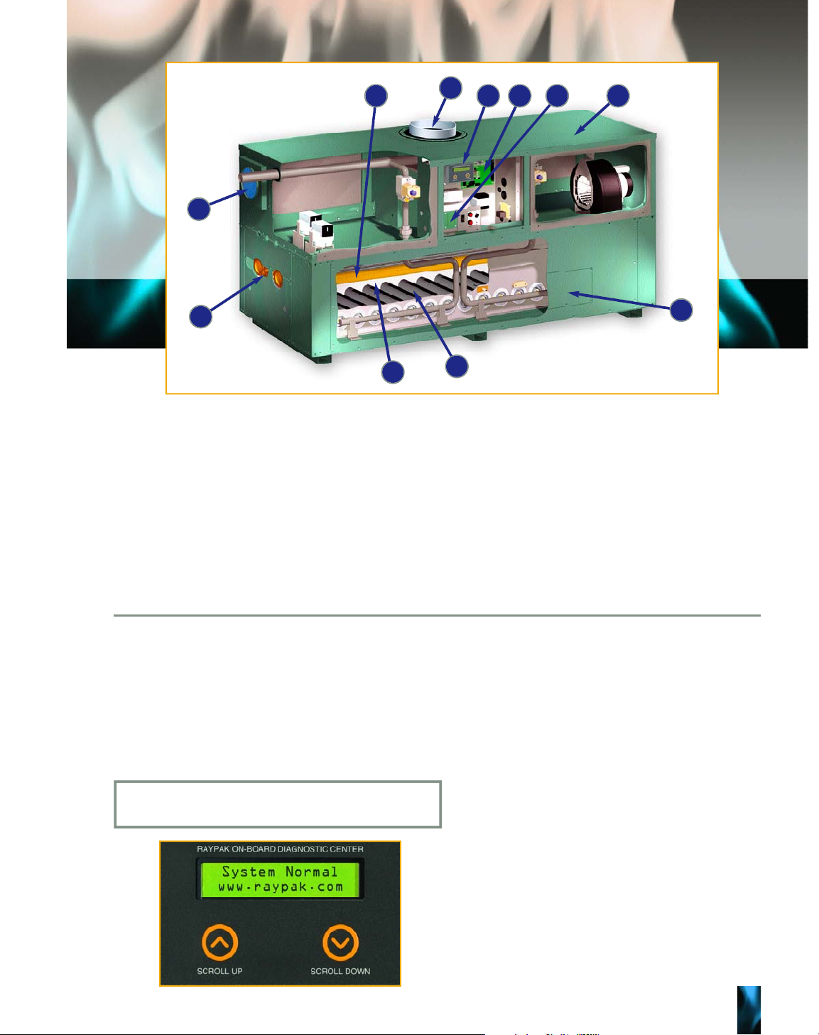
1 . Li gh tw eight R ef ra ct ory P a n e l s
Multi-piece ceramic fiber panels enhance combustion while minimizing heat retention.
2 . Fu ll y- enclosed Headers
Temperature sensors and lead wires/capillaries are
protected from weather, vandalism, and accidental
damage during installation and service.
3 . Fl ue Connec ti on
Top or back outlet flue connections offer greater
installation flexibility.
4 . Air Fi lt er
An easily-cleaned combustion air filter protects the
burners from airborne particles including flying
insects.
5 . O n - B o a r d Diag no st ic Ce nter
Factory mounted standard equipment (302-2342).
Gives relevant service feedback as well as possible
solutions to clear the fault. All in plain English, no
cryptic codes to decipher. The control stores up to
16 fault codes in its history file for the service technician to review.
6 . Stat us Di spla y Light s
Up to 12 high-intensity LED lights, visible up-front,
indicate the operating status of the boiler.
7 . C o n s t r u c t i o n
The cabinet and all internal parts are made from
galvanized, aluminized or stainless steel. The exterior is protected by textured powder-coat paint,
ideally designed for indoor or outdoor installations.
8 . C e n t r al P oint W i r i n g
Factory-made wire harnesses connect all electrical
components to an easy-to-troubleshoot circuit
board with multi-pin connectors.
9 . He at Exchan ge r Tu b e s
Time-proven copper finned tubes and optional
cupro-nickel tubes stand up to even the harshest
water conditions.
1 0 . B u r n e r s
Special stainless steel alloy pre-mix burners provide clean, robust combustion and meet all low
NOx regulations.
1 1 . HS I Ac ce ss Pa n e l
A small pane
l provides access to both the hot surface igniter and the flame sensor to aid inspection
and service.
4
5 6
1
3
1 0
2
1 1
9 8 7
On-Board Diagnostic Center
Raypak’s Hi Delta (302B thru 2342B) comes equipped with a microprocessor-controlled diagnostic control center that displays its
information on a 2x20 character LCD display in plain English. This control monitors system safeties, ignition faults and system
status, while storing up to 16 reported faults. Raypaks diagnostic center also monitors the fault outputs of the Fenwal ignition
control. The Fenwal’s flash codes are converted into real English fault codes that anyone can understand. The control is also
equipped with a SPDT dry contact relay output that is switched anytime a safety fault occurs. This can be used for a heater alarm
or a BMS safety interface.
Diagnostic Information
Safety Faults Ignition Control Faults
• Manual High Limit • Low Air
• Auto High Limit • Flame- No CFH
• Low Water Cut-off • Ignition Lockout
• Vent Pressure • Low HSI Current
• High Gas Pressure • Low 24VAC
• Low Gas Pressure • Internal Control Fault
• Controller Alarm
• Flow Switch
• Blower Switch
• Factory Option
• External Interlock
• Cold Water Run
Water Flow Sw Fault
Check Boiler Pump, Purge Air, Replace Flow Switch
Example Diagnostic Fault Report
3
Page 4

4
98%High-efficiency Hi Delta with optional CHX
condensing heating system
Hi Delta with CHX achieves unequaled 98% thermal efficiency at full fire. It combines
the reliability of the Hi Delta boiler with an optional CHX heat exchanger which prevents condensation in the heater’s primary combustion chamber. Self contained secondary heat exchanger can be inspected and maintained without disturbing the vent
or plumbing connections. The result is an ultra high efficiency heater that lasts.
(See Cat. 1000.17)
Flex Gas
TM
Dual-fuel boilers and water heaters
With its patented, CSA-certified rapid fuel switchover system, the Hi Delta FlexGas
is an ideal solution for interruptible-fuel applications (natural/propane gas).
(See Cat. #1000.20)
Options
S u r e R a c k
T M
K i t
The perfect solution for today’s most space challenged equipment rooms.
Stacking two Hi Delta 2342 boilers provides over 4.6MMBTU in just over
26 square feet plus clearances. All components (except pumps and PRV ’s )
are contained inside the cabinet, so there won’t be any gas valves or fans
hanging off the unit. The units remain fully serviceable even while racke d .
• For models 302B thru 2342B
• No Vent Offset Required
• Small Footprint
• Fits in Low-Ceiling Room
• Heavy-Duty Construction
• Easy Assembly
• All Hardware Included
• Still Allows for Complete Servicing
Sidewall Vent
Category III
Vertical Venting
Category I (Type B)
See Cat. 1000.16 for
complete SureRack Details
• For models 402B thru 2002B
• Top or rear CHX mounting options
• Up to 4.0MMBTU if used with the
SureRack racking system
• Fully-engineered rack systems simplify
jobsite installation and set-up
• Indoor/Outdoor installation
• Fully certified vent systems available
• Straight tube heat exchanger outlasts
other designs and facilitates scalefree operation – ideal for DHW
applications
• For models 302B thru 2342B
• Changeover takes less than one minute
• No mechanical components to remove
or replace
• Changerover can be accomplished
while firing: simply turn the key!
• Factory-installed and tested system
• CSA-Certified
Page 5

5
Simple Serviceability
Raypak’s easy-to-understand user interface, including onboard diagnostics and LED operating status lights, tells
the technician all he needs to know. All service/repair
components are readily accessible from the front for maximum installation flexibility.
Cold Water Start
It is commonly known that prolonged internal condensation will dramatically shorten the life of standard boilers and water heaters. While
Raypak boilers and water heaters can operate without harmful condensation at lower inlet water temperatures than the competition,
there are still applications that require reliable protection against harmful condensation caused by frequent, extended, cold water startups. Raypak’s Cold Water Start protection system utilizes a proportional three-way valve to bypass water from the boiler outlet to the
inlet during start-up, when the system return water temperature is below the minimum acceptable level.
Cold Water Run
For the same reason stated for Cold Water Starts, it is even more important to provide protection against condensation from cold inlet
water on systems where the return water temperature to the boiler will always be below the acceptable minimum. Raypak’s Cold Water
Run system utilizes a variable-speed pump to inject just the right amount of water from the main system loop into the boiler to maintain
the optimum inlet temperature. This approach allows the full capacity of the boiler to be utilized to meet the system load, while at the
same time continuously maintaining the optimum inlet water temperature to prevent condensation. (See Cat. #1000.19)
1 Diagnostic Control Center
2 Fenwal ignition control
3 Central point wiring board
4 Transformer
5 Pump delay relay
6 Manual reset high limit
7 Main power disconnect
8 Standby power switch
9 Status lights
Cold Water Start Cold Water Run
Cold Water Solution Options
31 2
4
5
9 8 7 6
Control Options
Raypak’s array of leading edge controllers offer features such as:
sequence-control of up to 40 boilers; PID technology; optimized
approach to outdoor reset; LonWorks or BMS interfacing; freeze protection and other energy-saving functions. Raypak’s controllers have
been specially designed to maximize the performance of its leadingedge Hi Delta boilers.
TempTracker
Designed to sequence multiple boilers up to
four total stages, whether it’s one to four
on/off boilers, two two-stage boilers, or one
boiler with up to four stages. It is available
factory-mounted or loose.
(See Cat. 5100.22)
RayTemp
Demand-based set-point control maximizes
energy savings in domestic hot water applications (See Cat. 5100.18)
Y-200 Boiler Sequencer
Provides additional functionality for multiple-boiler installations. Compatible with
LonWorks
®
Building Management Systems
(BMS) (See Cat. #5100.22)
Page 6

HD101 1/8 1.1 1/8 1.3 1/4 5.7
HD151 1/8 1.1 1/8 1.3 1/4 5.7
HD201 1/8 1.1 1/8 1.3 1/4 5.7
HD251 1/8 1.1 1/8 1.3 1/4 5.7
HD301 1/8 1.1 1/8 1.3 1/4 5.7
HD401 1/8 1.1 1/8 1.3 1/4 5.7
302B 1/8 1.3 1/4 5.7 1/2 7
402B 1/8 1.3 1/4 5.7 1/2 7
502B 1/8 1.3 1/4 5.7 1/2 7
652B 1/8 1.3 1/4 5.7 1/2 7
752B 1/8 1.3 1/2 7 3/4 11
902B 1/4 5.7 1/2 7 3/4 11
992B 1/4 6 1/2 7 3/4 11
1262B 1/4 6 3/4 11 1 14
1532B 1/2 7 1 14 1 14
1802B 3/4 11 1 14 1-1/2 15
2002B 3/4 11 1-1/2 15 1-1/2 15
2072B 3/4 11 1-1/2 15 1-1/2 15
2342B 1 14 1-1/2 15 1-1/2 15
Note: Current draw (Amps) is for pump only.
Soft
Water Hardness
HardMedium
HP Amps HP AmpsHP Amps
Hi Delta
Model
Floor* 0” 0” 0” 0”
Rear 1” 24” 12” 24”
Water side 12” 24” 36” 36”
Other side 1” 24” 36” 36”
Top 1” 1” U n o b s t r u c t e d U n o b s t r u c t e d
Front Open 24” Open 24”
Vent 2” 2” N/A N/A
Indoor
Minimum
Boiler
Side
Service
Outdoor
Minimum Service
* Do not install on carpeting.
6
H D 1 0 1 1 0 0 8 5 N / A 8 5 1 8 - 9 / 1 6 9 - 1 / 4 3 / 4 1 - 1 / 2 4 4 N / A 1 5 0 4 . 7
H D 1 5 1 1 5 0 1 2 8 N / A 1 2 8 2 1 - 7 / 8 1 0 - 7 / 8 3 / 4 1 - 1 / 2 4 4 N / A 1 7 5 4 . 7
H D 2 0 1 1 9 9 1 6 9 N / A 1 6 9 2 5 - 1 / 1 6 1 2 - 1 / 2 3 / 4 1 - 1 / 2 5 4 N / A 2 0 0 4 . 7
H D 2 5 1 2 5 0 2 1 3 N / A 2 1 3 2 8 - 5 / 1 6 1 4 - 1 / 8 3 / 4 1 - 1 / 2 5 4 N / A 2 2 5 4 . 7
H D 3 0 1 2 9 9 2 5 4 N / A 2 5 4 3 1 - 9 / 1 6 1 5 - 3 / 4 3 / 4 1 - 1 / 2 5 4 N / A 2 5 0 4 . 7
H D 4 0 1 3 9 9 3 3 5 N / A 3 3 9 3 8 - 1 / 1 6 1 9 3 / 4 1 - 1 / 2 6 4 N / A 3 0 0 4 . 7
3 0 2 B 3 0 0 2 5 2 2 6 1 2 5 5 3 6 1 8 3 / 4 2 5 6 1 8 3 8 0 6
4 0 2 B 3 9 9 3 3 5 3 4 7 3 3 9 4 3 2 1 - 1 / 2 3 / 4 2 6 6 1 8 - 1 / 2 4 4 5 6
5 0 2 B 5 0 0 4 2 0 4 3 5 4 2 5 5 0 2 5 1 - 1 / 4 2 6 6 2 2 5 4 5 6
6 5 2 B 6 5 0 5 4 6 5 6 6 5 5 3 6 0 - 1 / 2 3 0 - 1 / 4 1 - 1 / 4 2 8 6 2 7 - 1 / 4 5 9 0 6
7 5 2 B 7 5 0 6 3 0 6 5 3 6 3 8 6 7 - 1 / 2 3 3 - 3 / 4 1 - 1 / 4 2 8 6 3 0 - 3 / 4 6 7 5 6
9 0 2 B 9 0 0 7 5 6 7 8 3 7 6 5 7 8 3 9 1 - 1 / 4 2 8 6 3 6 7 4 0 7
9 9 2 B 9 9 0 8 3 2 8 6 1 8 4 2 5 7 - 1 / 8 2 8 - 9 / 1 6 2 2 - 1 / 2 1 0 1 0 1 6 - 1 3 / 1 6 9 0 0 < 1 2
1 2 6 2 B 1 2 6 0 1 0 5 8 1 0 9 6 1 0 7 1 6 8 - 1 / 2 3 4 - 1 / 4 2 2 - 1 / 2 1 2 1 0 2 0 - 9 / 1 6 1 0 1 0 < 1 2
1 5 3 2 B 1 5 3 0 1 2 8 5 1 3 3 1 1 3 0 1 7 9 - 7 / 8 3 9 - 1 5 / 1 6 2 2 - 1 / 2 1 2 1 0 2 4 - 3 / 8 1 2 2 5 < 1 2
1 8 0 2 B 1 8 0 0 1 5 1 2 1 5 6 6 1 5 3 0 9 1 - 1 / 8 4 5 - 9 / 1 6 2 2 - 1 / 2 1 4 1 0 2 8 - 1 / 8 1 3 5 0 < 1 2
2 0 0 2 B ª 1 9 9 9 1 6 7 9 1 7 3 9 1 6 9 9 1 0 2 - 1 / 2 5 1 - 1 / 4 2 2 - 1 / 2 1 4 1 0 3 1 - 1 5 / 1 6 1 4 5 0 < 1 2
2 0 7 2 B 2 0 7 0 1 7 3 9 1 8 0 1 1 7 6 0 1 0 2 - 1 / 2 5 1 - 1 / 4 2 2 - 1 / 2 1 4 1 0 3 1 - 1 5 / 1 6 1 4 5 0 < 1 2
2 3 4 2 B 2 3 4 0 1 9 6 6 2 0 3 6 1 9 8 9 1 1 3 - 7 / 8 5 6 - 1 5 / 1 6 2 2 - 1 / 2 1 6 1 0 3 5 - 1 1 / 1 6 1 5 2 0 < 1 2
Ref.
Dwg.
pg. 5
Amps
‡
( C a t . I )
Operating
Weight
(lbs.)
T
Ø
W
H
NPTKFlue Ø
G
NPT
A
Width
B
MBTUH Output*
8 7 %†( C a t . I I )
Type W H
8 5 %
Dimensions (in.)
* Ratings for models HD101-HD401 for natural or propane gas and for elevations up to 2,000 ft. above sea level . For higher elevations, consult the factory.
* Ratings for models 302B-2342B for natural or propane gas and for elevations up to 4,500 ft. above sea level . For higher elevations, consult the factory.
† Add “E” Suffix to model number.
‡ Current draw is for heater only. (Supply breaker must have a delayed trip.)
ª
Natural gas only. Not available for propane.
Hi Delta
M o d e l
MBTUH
Input*
Type H
1
3
2
California Bill AB-1953
Raypak is the first manufacturer to fully comply with California
bill A B - 1 9 5 3 . This is new legislation, mandating the maximum
lead content to be less than .25% of the wetted surface area.
This legislation went into effect January 1, 2010 and complience
has been verified by CSA.
Page 7

7
Page 8

8
HD101 13 <1.0 14 44 8.8 4 17 1.4
HD151 13 <1.0 20 44 8.8 6 26 3.1 13 1.0
HD201 13 3.4 27 44 8.9 8 34 5.4 17 1.3
HD251 13 <1.0 34 44 9.2 10 43 8.5 21 2.1 14 <1.0
HD301 13 <1.0 41 44 9.4 12 25 3.1 17 1.4 13 <1.0
HD401 22 2.4 30 44 9.8 15 34 5.6 22 2.5 17 1.4
302B 20 <1.0 25 90 9.8 6 50 3.3 25 <1.0
402B 20 <1.0 34 90 10.0 7 67 5.8 34 1.4 22 <1.0
502B 21 <1.0 40 90 10.4 9 84 9.1 42 2.3 28 1.1 21 <1.0
652B 27 1.1 40 90 10.8 12 55 4.1 36 1.8 27 1.1
752B 32 1.5 40 90 11.3 14 63 5.7 42 2.6 32 1.5
902B 38 2.2 40 90 11.7 17 76 8.3 50 3.8 38 2.2
992B 42 1.3 40 132 13.1 13 83 5.2 55 2.3 42 1.3
1262B 53 2.4 40 132 14.8 16 106 9.6 71 4.3 53 2.4
1532B 64 4.0 40 132 16.5 19 129 15.7 86 7.1 64 4.0
1802B 76 6.0 40 132 18.3 23 101 10.7 76 6.0
2002B 84 7.9 40 132 19.0 25 112 13.8 84 7.9
2072B 87 8.5 40 132 19.0 26 116 14.8 87 8.5
2342B 98 12.1 40 132 21.4 30 131 21.1 98 12.1
20°F DT
Pressure Drops
40°F DT30°F DT
GPM
DP Ft
GPM
DP Ft
GPM
DP Ft
Hi Delta
Model
10°F DT
GPM
DP Ft
Minimum Flow
GPM
DP Ft DT °F
Maximum Flow
GPM
DP Ft DT °F
Flow Rates
HD101 9 20 1.8 3.8 7 26 3.0 6.3 4 45 9.2 18.0 1-1/2”
HD151 13 20 1.8 3.8 10 26 3.1 6.3 6 45 9.2 18.1 1-1/2”
HD201 17 20 1.9 3.9 13 26 3.2 6.4 8 45 9.4 18.2 1-1/2”
HD251 21 20 1.9 3.9 16 26 3.2 6.5 9 45 9.6 18.5 1-1/2”
HD301 25 20 1.9 3.9 20 26 3.2 6.5 11 45 9.8 18.7 1-1/2”
HD401 31 22 2.4 4.8 26 26 3.3 6.6 15 45 10.3 19.1 1-1/2”
302B 13 40 2.0 5.1 10 52 3.3 8.3 7 74 6.6 16.3 2”
402B 17 40 2.0 5.1 13 52 3.4 8.4 9 74 6.8 16.4 2”
502B 21 40 2.1 5.2 16 52 3.5 8.6 12 73 6.9 16.3 2”
652B 28 40 2.2 5.3 20 55 4.1 9.7 15 72 7.0 16.2 2”
752B 30 42 2.6 6.0 17 73 7.5 16.9 14 90 11.3 25.1 2”
902B 30 51 3.9 8.7 21 73 7.8 17.2 17 90 11.7 25.5 2”
992B 28 60 2.7 5.2 17 98 7.3 13.3 13 132 13.1 23.6 2-1/2”
1262B 30 72 4.4 7.9 19 115 11.3 19.4 16 132 14.8 25.3 2-1/2”
1532B 30 86 7.1 11.9 22 120 13.7 22.5 20 132 16.5 27.0 2-1/2”
1802B 30 102 10.9 17.4 26 120 15.1 23.9 23 132 18.3 28.7 2-1/2”
2002B 30 112 13.9 21.6 26 132 19.0 29.5 26 132 19.0 29.5 2-1/2”
2072B 30 117 15.1 23.4 27 132 19.0 29.5 27 132 19.0 29.5 2-1/2”
2342B 30 132 21.4 31.8 30 132 21.4 31.8 30 132 21.4 31.8 2-1/2”
302BE 20 <1.0 26 90 9.8 6 52 3.3 26 <1.0
402BE 20 <1.0 35 90 10.0 8 69 5.8 35 1.5 23 <1.0
502BE 22 <1.0 40 90 10.4 10 87 9.1 44 2.5 29 1.1 22 <1.0
652BE 28 1.1 40 90 10.8 13 57 4.4 38 2.0 28 1.1
752BE 33 1.6 40 90 11.3 15 65 6.1 44 2.8 33 1.6
902BE 39 2.3 40 90 11.7 17 78 8.9 52 4.1 39 2.3
992BE 43 1.4 40 132 13.1 13 86 5.6 57 2.5 43 1.4
1262BE 55 2.6 40 132 14.8 17 110 10.3 73 4.6 55 2.6
1532BE 67 4.3 40 132 16.6 20 132 16.5 89 7.6 67 4.3
1802BE 78 6.5 40 132 18.3 24 104 11.5 78 6.5
2002BE 87 8.5 40 132 19.0 26 116 14.8 87 8.5
2072BE 90 9.1 40 132 19.0 27 120 15.8 90 9.1
2342BE 102 12.9 40 132 21.4 31 132 22.6 102 12.9
Less than Minimum Flow
Exceeds Maximum Flow
Exceeds Maximum Flow
MTS
Hi Delta
Model
Soft
DT °F
GPM
DP Ft
SHL*
Water Hardness
20°F DT
Pressure Drops
40°F DT30°F DT
GPM
DP Ft
GPM
DP Ft
GPM
DP Ft
Hi Delta
Model
10°F DT
GPM
DP Ft
Minimum Flow
GPM
DP Ft DT °F
Maximum Flow
GPM
DP Ft DT °F
Flow Rates
Less than Minimum Flow
N OT E S : 98% efficiency available with condensing heat exchanger. (See Specialty Models on pg. 4.) Minimum flow rates in closed systems may be reduced to a flow rate consistent with a 40°F DT.
Maximum flow rates are limited by maximum acceptable velocity through the heat exchanger tubes and may be increased by 10% for closed heating systems. Pressure drop would increase 21%.
*SHL = Calculated at 100 feet effective pipe length.
Less than Minimum Flow
Exceeds
Maximum Flow
Medium
DT °F
GPM
DP Ft
SHL*
Hard
DT °F
GPM
DP Ft
SHL*
Page 9

9
NOTE: 98% efficiency available with condensing heat exchanger. (See Specialty Models on pg. 4.)
HD101 100 1020 510 340 255 204 170 146 128 113 102 93 85 78 73 68
HD151 150 1531 765 510 383 306 255 219 191 170 153 139 128 118 109 102
HD201 199 2031 1015 677 508 406 338 290 254 226 203 185 169 156 145 135
HD251 250 2551 1276 850 638 510 425 364 319 283 255 232 213 196 182 170
HD301 299 3051 1526 1017 763 610 509 436 381 339 305 277 254 235 218 203
HD401 399 4024 2012 1341 1006 805 671 575 503 447 402 366 335 310 287 268
302B 300 3055 1527 1018 764 611 509 436 382 339 305 278 255 235 218 204
402B 399 4063 2031 1354 1016 813 677 580 508 451 406 369 339 313 290 271
502B 500 5091 2545 1697 1273 1018 848 727 636 566 509 463 424 392 364 339
652B 650 6618 3309 2206 1655 1324 1103 945 827 735 662 602 552 509 473 441
752B 750 7636 3818 2545 1909 1527 1273 1091 955 848 764 694 636 587 545 509
902B 900 9164 4582 3055 2291 1833 1527 1309 1145 1018 916 833 764 705 655 611
992B 990 10080 5040 3360 2520 2016 1680 1440 1260 1120 1008 916 840 775 720 672
1262B 1260 12829 6415 4276 3207 2566 2138 1833 1604 1425 1283 1166 1069 987 916 855
1532B 1530 15578 7789 5193 3895 3116 2596 2225 1947 1731 1558 1416 1298 1198 1113 1039
1802B 1800 18327 9164 6109 4582 3665 3055 2618 2291 2036 1833 1666 1527 1410 1309 1222
2002B 1999 20353 10177 6784 5088 4071 3392 2908 2544 2261 2035 1850 1696 1566 1454 1357
2072B 2070 21076 10538 7025 5269 4215 3513 3011 2635 2342 2108 1916 1756 1621 1505 1405
2342B 2340 23825 11913 7942 5956 4765 3971 3404 2978 2647 2383 2166 1985 1833 1702 1588
Hi Delta
M o d e l
Temperature Rise (°F)
10
Recovery Rates (GPH)
M B T U H
I n p u t
20 30 40 50 60 70 80 90 100 110 120 130 140 150
HD101 100 1020 510 340 255 204 170 146 128 113 102 93 85 78 73 68
HD151 150 1531 765 510 383 306 255 219 191 170 153 139 128 118 109 102
HD201 199 2031 1015 677 508 406 338 290 254 226 203 185 169 156 145 135
HD251 250 2551 1276 850 638 510 425 364 319 283 255 232 213 196 182 170
HD301 299 3051 1526 1017 763 610 509 436 381 339 305 277 254 235 218 203
HD401 399 4071 2036 1357 1018 814 679 582 509 452 407 370 339 313 291 271
302B 300 3091 1545 1030 773 618 515 442 386 343 309 281 258 238 221 206
402B 399 4111 2055 1370 1028 822 685 587 514 457 411 374 343 316 294 274
502B 500 5152 2576 1717 1288 1030 859 736 644 572 515 468 429 396 368 343
652B 650 6697 3348 2232 1674 1339 1116 957 837 744 670 609 558 515 478 446
752B 750 7727 3864 2576 1932 1545 1288 1104 966 859 773 702 644 594 552 515
902B 900 9273 4636 3091 2318 1855 1545 1325 1159 1030 927 843 773 713 662 618
992B 990 10200 5100 3400 2550 2040 1700 1457 1275 1133 1020 927 850 785 729 680
1262B 1260 12982 6491 4327 3245 2596 2164 1855 1623 1442 1298 1180 1082 999 927 865
1532B 1530 15764 7882 5255 3941 3153 2627 2252 1970 1752 1576 1433 1314 1213 1126 1051
1802B 1800 18545 9273 6182 4636 3709 3091 2649 2318 2061 1855 1686 1545 1427 1325 1236
2002B 1999 20596 10298 6865 5149 4119 3433 2942 2574 2288 2060 1872 1716 1584 1471 1373
2072B 2070 21327 10664 7109 5332 4265 3555 3047 2666 2370 2133 1939 1777 1641 1523 1422
2342B 2340 24109 12055 8036 6027 4822 4018 3444 3014 2679 2411 2192 2009 1855 1722 1607
302BE 300 3164 1582 1055 791 633 527 452 395 352 316 288 264 243 226 211
402BE 399 4208 2104 1403 1052 842 701 601 526 468 421 383 351 324 301 281
502BE 500 5273 2636 1758 1318 1055 879 753 659 586 527 479 439 406 377 352
652BE 650 6855 3427 2285 1714 1371 1142 979 857 762 685 623 571 527 490 457
752BE 750 7909 3955 2636 1977 1582 1318 1130 989 879 791 719 659 608 565 527
902BE 900 9491 4745 3164 2373 1898 1582 1356 1186 1055 949 863 791 730 678 633
992BE 990 10440 5220 3480 2610 2088 1740 1491 1305 1160 1044 949 870 803 746 696
1262BE 1260 13287 6644 4429 3322 2657 2215 1898 1661 1476 1329 1208 1107 1022 949 886
1532BE 1530 16135 8067 5378 4034 3227 2689 2305 2017 1793 1613 1467 1345 1241 1152 1076
1802BE 1800 18982 9491 6327 4745 3796 3164 2712 2373 2109 1898 1726 1582 1460 1356 1265
2002BE 1999 21080 10540 7027 5270 4216 3513 3011 2635 2342 2108 1916 1757 1622 1506 1405
2072BE 2070 21829 10915 7276 5457 4366 3638 3118 2729 2425 2183 1984 1819 1679 1559 1455
2342BE 2340 24676 12338 8225 6169 4935 4113 3525 3085 2742 2468 2243 2056 1898 1763 1645
Hi Delta
M o d e l
Temperature Rise (°F)
10
Recovery Rates (GPH)
M B T U H
I n p u t
20 30 40 50 60 70 80 90 100 110 120 130 140 150
Hi Delta
M o d e l
Temperature Rise (°F)
10
Recovery Rates (GPH)
M B T U H
I n p u t
20 30 40 50 60 70 80 90 100 110 120 130 140 150
Page 10

Notes:
1 Standard on on/off boilers (H4); Optional on all others
2 Standard on Models 302B and 402B; Optional on Models 502B-902B
3 Optional on Models 302B and 402B; Standard on Models 502B-902B
4 Standard on 992B; Optional on 1262B-2342B
5 Not available on Model 992B; Standard on Models 1262B-2342B
v v = Standard V V = Optional
Water Heaters (Type WH)
H D 1 0 1 - H D 4 0 1 3 0 2 B - 9 0 2 B 9 9 2 B - 2 3 4 2 B
Boilers (Type H)
HD101-HD401 302B-902B 992B-2342B
A S M E , National Board Registered, 160 PSI H Stamp v v v N/A N/A N/A
HLW Stamp N/A N/A N/A v v v
Heat Exchanger Tubes Copper v v v v v v
Cupro Nickel V V V V V V
Headers Bronze V V V v v v
Cast Iron v v v V V V
Pressure Relief Valve 3 0 , 4 5 , 75 & 150 PSI A va i l a b l e V V V V V V
60 & 125 v v v v v v
Temperature & Pressure Gauge v v v v v v
Pump – 120V, Single-Phase V V V V V V
120V Power Supply With 120V/24V Transformer v v v v v v
Pump Time Delay Single Phase v v v v v v
Diagnostic Display Central 16-Event Memory N/A v v N/A v v
Temperature Controller B-20: On/Off, Mechanical V V V V V V
B-28: On/Off, Digital V V V V V V
B-6: 2-Stage, Mechanical V V V V V V
B-26–B-27: 2-Stage, Digital V V V V V V
B-21–B-23: 4-Stage, Digital V V V V V V
B-24: 2-Stage, Raytemp (Digital) N/A V V N/A V V
B-25: 4-Stage, Raytemp (Digital) V V V V V V
Y-200 Series, Digital V V V V V V
Hot Surface Ignition System 3-try v v v v v v
1-try N/A V V N/A V V
High Gas Pressure Switch V V V V V V
Low Gas Pressure Switch V V v V V v
B l o c ked Vent and Air Pressure Switches v v v v v v
High Limit Switch Manual Reset, Fixed v N/A N/A v N/A N/A
Manual Reset, Adjustable V v v V v v
Automatic Reset, Adjustable V (1) V V V V
Low Water Cut-Off, 24V With manual reset and test button V V V V V V
Flow Switch v v v v v v
Firing Mode On/Off (H4, WH1) V (2) V v (2) V
2-Stage (H3, WH3) v (3) V V (3) V
3-Stage (H8, WH8) N/A N/A (4) N/A N/A (4)
4-Stage (H9, WH9) N/A N/A (5) N/A N/A (5)
4” WC Supply Pressure Natural Gas Only v V (6) v V (6)
TruSeal Direct Vent System v V V v V V
Air Filter, Room Air v v v v v v
Air Filter, Ducted Outside Air v V V v V V
Efficiency 84% (Category I) v v v N/A N/A N/A
(98% ava i l a b l e ; See Specialty Models) 85% (Category I) N/A N/A N/A v v v
(402B - 2002B only) 87% (Category II) N/A V V N/A N/A N/A
Combustible Floor Rated v v v v v v
Alarm System V V V V V V
Vent Terminal Outdoor and Through-the-Wall V V V V V V
Right-Hand Water Connections V V V V V V
CSD-1/GE GAP Control System N/A (7) V N/A (7) V
Low NOx Compliance Meets all current requirements v v (8) v v (8)
Cold Water Start Cold water protection systems N/A V V N/A V V
Cold Water Run Cold water protection systems V V V V V V
6 Option but not available on Model 2002B
7 Not applicable for Models 302B and 402B; Optional for Models 502B-902B
8 Standard on Models 992B-2002B; Models 2072B and 2342B
require site testing and have different emissions requirements
(Consult factory)
R a y p a k , I n c . • 2151 Eastman Ave., Oxnard, CA 93030 • phone: (805) 278-5300 • fax: (800) 872-9725 • www.raypak.com
Cat. No. 1100.12D Effective 06-15-10 Replaces: 11-15-09
 Loading...