

Page 1
Page 2
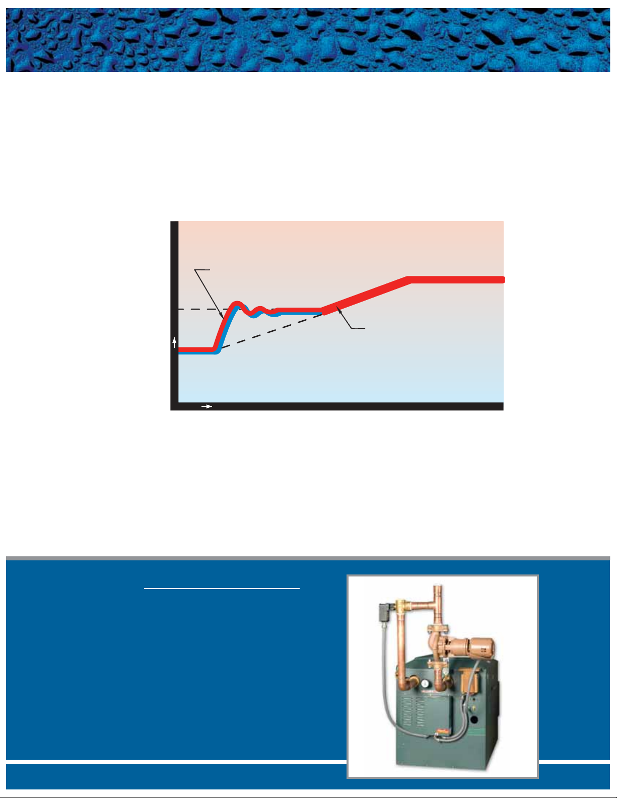
It is commonly known that prolonged internal condensation will dramatically shorten the life of standard boilers and
water heaters.While Raypak boilers and water heaters can operate without harmful condensation at lower inlet water
temperatures than the competition, there are still applications that require reliable protection against harmful condensation caused by frequent,extended,cold water start-ups.Raypak’s Cold Water Start protection system utilizes a proportional three-way valve to bypass water from the boiler outlet to the inlet during start-up, when the system return
water temperature is below the minimum acceptable level.
COLD WATER START
Raypak’s Cold Water Start system:
• Continuously monitors and adjusts inlet water temperature to prevent condensation
• Regulates minimum inlet water temperature during system start-up
• Shuts down boiler if the minimum inlet water temperature is not achieved
• Eliminates job site set-up with proprietary self-tuning controller and system-matched components
• Utilizes proportional three-way valve to achieve bypass
• Allows high-temperature system operation without cycling on high-limit
• Activates alarm if shutdown occurs (option)
CCoommmmeerrcciiaall HHyyddrroonniicc HHeeaattiinngg
Office Buildings •
Factories/Warehouses •
Greenhouses •
DDoommeessttiicc HHoott WWaatteerr SSuuppppllyy
Restaurants •
Weekend Shut-down •
(e.g. 6-day/week shopping center)
Dump Loads •
87% Hot Water Supply Boiler •
Intermittent Industrial Process •
AAPPPPLLIICCAATTIIOONNSS
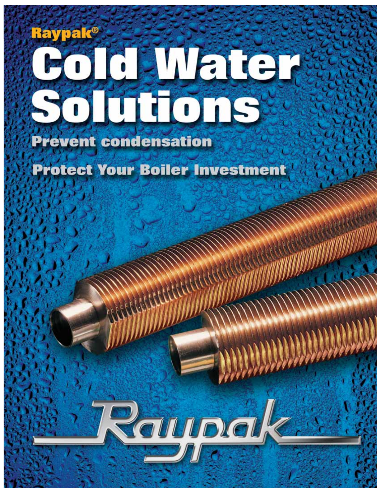
Boiler Start-Up Cycle
MIN INLET
TEMP SETTING
START-UP
TEMP
TEMPERATURE
TIME
BLENDED BOILER
INLET TEMP
SYSTEM RETURN
SYSTEM RETURN NOW AT
OR ABOVE MINIMUM INLET
SETTING. BYPASS CLOSED,
FULL SYSTEM FLOW
STABLE SYSTEM TEMP
Page 3

For the same reason stated for Cold Water Starts,it is even more important to provide protection against condensation
from cold inlet water on systems where the return water temperature to the boiler will always be below the acceptable
minimum. Raypak’s Cold Water Run system utilizes a variable-speed pump to inject just the right amount of water
from the main system loop into the boiler to maintain the optimum inlet temperature.This approach allows the full
capacity of the boiler to be utilized to meet the system load,while at the same time continuously maintaining the optimum inlet water temperature to prevent condensation.
COLD WATER RUN
Raypak’s Cold Water Run system:
• Continuously monitors and adjusts inlet water temperature to prevent condensation
• Regulates minimum inlet water temperature regardless of system temperature
• Shuts down boiler if the minimum inlet water temperature is not achieved
• Protects boiler from constant low return water temperatures with its proprietary self-tuning controller
• Utilizes variable-speed injector pump to control boiler loop temperature
• Activates alarm if shutdown occurs (option)
• Pool Heating
• Low-temperature Industrial Process
• Very Low-temperature Return Water
(e.g. convalescent hospital domestic
hot water)
AAPPPPLLIICCAATTIIOONNSS
Boiler Start-Up Cycle
BLENDED BOILER
INLET TEMP
MIN INLET
TEMP SETTING
SYSTEM RETURN
START-UP
TEMP
TEMPERATURE
TIME
Page 4

COLD WATER START
COLD WATER RUN
Cold Water Start J-Box Assembly Typical Cold Start Plumbing
Pictorial-Not to Scale
Cold Water Run J-Box Assembly Typical Cold RunPlumbing
Pictorial-Not to Scale
3-WAY
VALVE
BOILER
BOILER
PUMP
TO
SYSTEM
SYSTEM
PUMP
BOILER
BOILER
PUMP
FROM
SYSTEM
VARIABLE SPEED
INJECTOR PUMP
TO
SYSTEM
SYSTEM
PUMP
FROM
SYSTEM
Page 5
TECHNICAL DATA
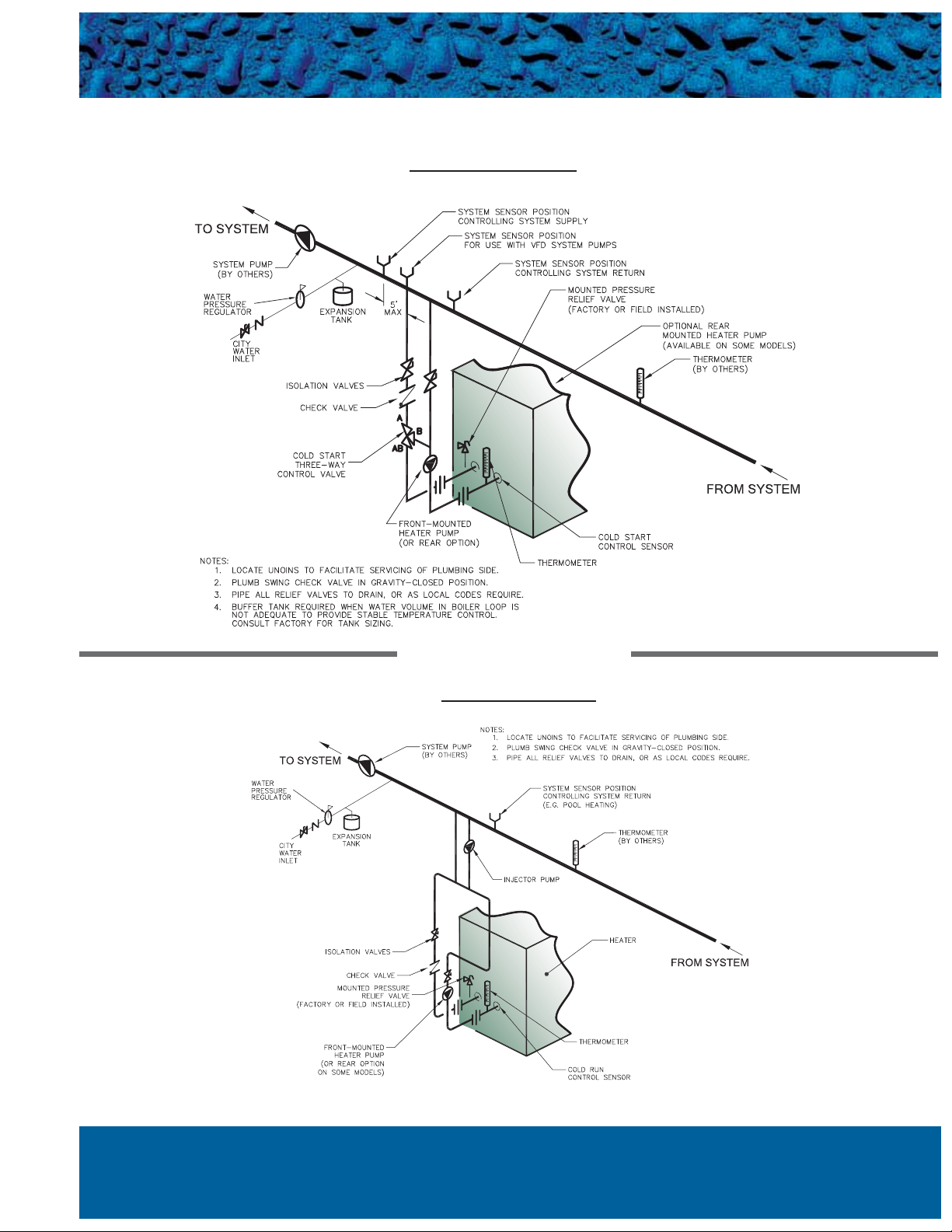
COLD WATER START
COLD WATER RUN
* Items required for cold water operation are shown.
Other standard system components have been omitted for clarity.
* Items required for cold water operation are shown. Other standard system components have been omitted for clarity.
TYPICAL BOILER PIPING*
TYPICAL BOILER PIPING*
Page 6

Catalog No.: 1000.19C Effective: 06-15-08 Replaces: 01-01-07
Raypak Inc., 2151 Eastman Ave., Oxnard, CA 93030
(805) 278-5300 Fax (800) 872-9725
MULTIPLE UNIT COLD WATER START
Total System Load
(MBTUH)
Three-Way Diverting Valve Specifications
Valve Size Cv GPM
P
500-900 2” NPT 57 70 3.5’
901-1,800 2-1/2” NPT 74 100 4.2’
1,801-3,000 2-1/2” NPT 100 150 5.2’
3,001-4,000 4” Flange 152 220 4.8’
4,001-6,000 4” Flange 254 330 3.9’
6,001-8,000 4” Flange 327 440 4.2’
Notes:
1. Maximum of 4 boilers per system.
2. Many variables can impact the proper valve sizing for multiple boilers. This sizing is provided as a guide. When in doubt consult the factory.
3. Multi-unit system ALWAYS shipped loose- Not available mounted.
4. 4” flanges, bolts and gaskets supplied by others. Multi-units with 4” valves are to be used on hydronic heating only.The valve body is cast
iron.
TECHNICAL DATA
 Loading...