

Page 1

OPERATING AND
INSTALLATION
INSTRUCTIONS
Models
0030B, 0042B, 0066B, 0090B
0135B, 0180B
Type H
RESIDENTIAL BOILERS
Catalog No.: 2100.50P
Effective: 11-01-99
Replaces: 6-01-99
FOR YOUR SAFETY
Do not store or use gasoline or other flammable vapors and liquids or other combustible materials
in the vicinity of this or any other appliance. To do so may result in an explosion or fire.
WARNING: Improper installation, adjustment, alteration, service or maintenance can cause
property damage, personal injury or loss of life. Refer to the user's information manual provided
with this boiler. Installation and service must be performed by a qualified installer, service agency
or the gas supplier.
FOR YOUR SAFETY
WHAT TO DO IF YOU SMELL GAS
*Do not try to light any appliance.
*Do not touch any electrical switch; do not use any phone in your building.
*Immediately call your gas supplier from a neighbor's phone. Follow the gas supplier's
instructions.
*If you cannot reach your gas supplier, call the fire department.
THIS MANUAL SHOULD BE MAINTAINED IN LEGIBLE CONDITION
AND KEPT ADJACENT TO THE BOILER OR KEPT IN A SAFE PLACE
FOR FUTURE REFERENCE.
®
P/N 240488
Page 2

Contents
3 1. RECEIVING EQUIPMENT
3 2. GENERAL SPECIFICATIONS AND DIMENSIONS
4 3. INSTALLATION PROCEDURES
4 - Code Requirements
4 - Mounting Base
4 - Clearance Requirements
4 - Combustion/Ventilation Air
5 - Venting Connections
7 - Vent Damper Installation
10 - Gas Supply Connections
10 - Water Connections & System Piping
14 - Electrical Wiring
22 4. SERVICING PROCECURES
22 - General Locations of Controls
22 - Sequence of Operation
23 - Start Up Procedures
28 - Safe Shutdown Test
28 - Normal Inspection Procedures
29 - Repair Section
31 5. TROUBLE SHOOTING GUIDE
33 - Adjustments/Replacements of Components
34 6. REPLACEMENT PARTS LIST
These instructions are provided to assure the proper
installation and operation of Raypak boilers. Should
questions arise regarding the specifications, installation, operation or servicing of these boilers, we suggest
that the local Sales representative or the factory be
consulted.
2
Page 3
1. RECEIVING EQUIPMENT
L
On receipt of your equipment it is suggested that
you visually check for external damage to the carton. If
the carton is damaged, it is suggested that a note be
made on the Bill of Lading when signing for equipment.
Remove the boiler from the carton and if it is damaged
report the damage to the carrier immediately. Be
sure that you receive the number of packages indicated
on the Bill of Lading. Claims for shortages and
damages must be filed with carrier by consignee.
Purchased parts are subject to replacement only
under the manufacturer's warranty. Debits for defective
replacement parts will not be accepted and defective
parts will be replaced in kind only per our standard
warranties.
When ordering parts, you must specify Model and
Serial Number of boiler. When ordering under warranty
conditions, you must also specify date of installation.
Raypak recommends that this manual be reviewed thoroughly before installing your Raypak
Boiler. If there are any questions which this manual
does not answer, please contact your local Raypak
representative.
2. GENERAL SPECIFICATIONS
The Raypak hydronic boilers are design certified by
the American Gas Association, and tested under the
requirements of the American National Standard, ANSI
Z21.13. Each boiler has been constructed and pressure
tested in accordance with the requirements of Section
IV of the American Society of Mechanical Engineers
Code, and factory fire tested.
The boilers are designed for indoor installation with
a built-in drafthood, and a built-in sub-base for combustible flooring. Models are available with standing pilot,
or with intermittent ignition device (I.I.D.). The boilers
are equipped with the following components: water
circulation pump, pressure relief valve, temperature/
pressure gauge, adjustable high limit switch, drain
valve, fast response temperature sensor, 40 VA transformer, pump relay, vent thermal switch, flame roll-out
switch, and redundant combination gas valve for use
with either natural or propane gases. Two-staged gas
valve (50% firing on 1st stage) is standard on models
H-0090, H-0135 and H-0180.
The automatic ignition models and some standing
pilot models are provided with a plug-in connector that
is compatible with the Honeywell D80D vent damper.
Similar type vent dampers made by other manufacturers, and design certified by a nationally-recognized
testing Agency, under the ANSI Z21.66 standards, may
also be used.
Follow the installation instructions furnished with the
vent damper package. The plug-in connector can also
be used with power venters. Refer to the specific
installation instructions supplied by the power vent
manufacturer.
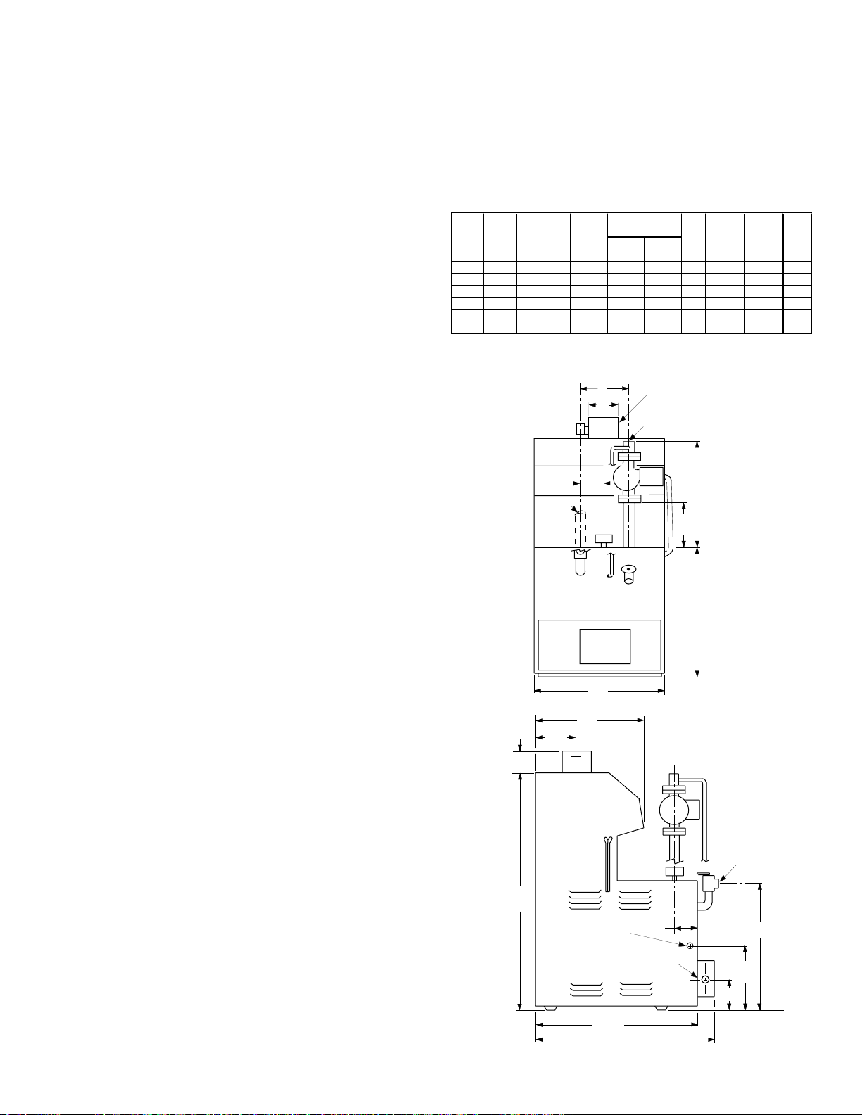
SPECIFICATIONS AND DIMENSIONS
HEATING NET K
INPUT CAPACITY I=B=R WATER GAS VENT
MODE
MBH MBH RATING NPT. NPT. A B C DIA.
H-0030 30 25 22 1" 1/2" 11" 5 3/4 5 1/2 4"
H-0042 42 35 30 1" 1/2" 11" 5 3/4 5 1/2 4"
H-0066 66 54 47 1" 1/2" 11" 5 3/4 5 3/4 5"
H-0090 90 74 64 1" 1/2" 11" 5 3/4 5 3/4 5"
H-0135 135 109 95 1 1/4" 1/2" 18" 6 1/4 6 1/4 6"
H-0180 180 148 129 1 1/4" 1/2" 18" 6 1/4 8.0 7"
3
OUTLET
16
1
/
4
2
C
1
/
33
4
THERMOSTAT CONN
(ELECTRICAL CONN
ON OTHER SIDE)
CONNECTIONS
B
K
1
/
8
A
1
/
22
8
PIPING
AUTOMATIC
VENT DAMPER
(FIELD INSTALLED)
INLET
1
/
3
4
GAS
CONN
1
/
26
2
6
MIN
11
19
7
/
8
3/4 NPT PIPE
TO DRAIN
1
/
12
5
Fig. #8978.1
18
2
3
Page 4
3. INSTALLATION PROCEDURES
CODE REQUIREMENTS
Installation must be in accordance with local
codes, or, in the absence of local codes, with the latest
editions of the National Fuel Gas Code, ANSI Z223.1,
and the National Electrical Code, ANSI/NFPA 70. In
Canada installations must conform with the current
CAN/CGA B149.1 or .2 and the Canadian Electrical
Code Part 1 CSA C22.2 No.1. Where required by the
authority having jurisdiction, the installation must conform to American Society of Mechanical Engineers
Safety Code for Controls and Safety Devices for Automatically Fired Boilers, No. CSD-1.
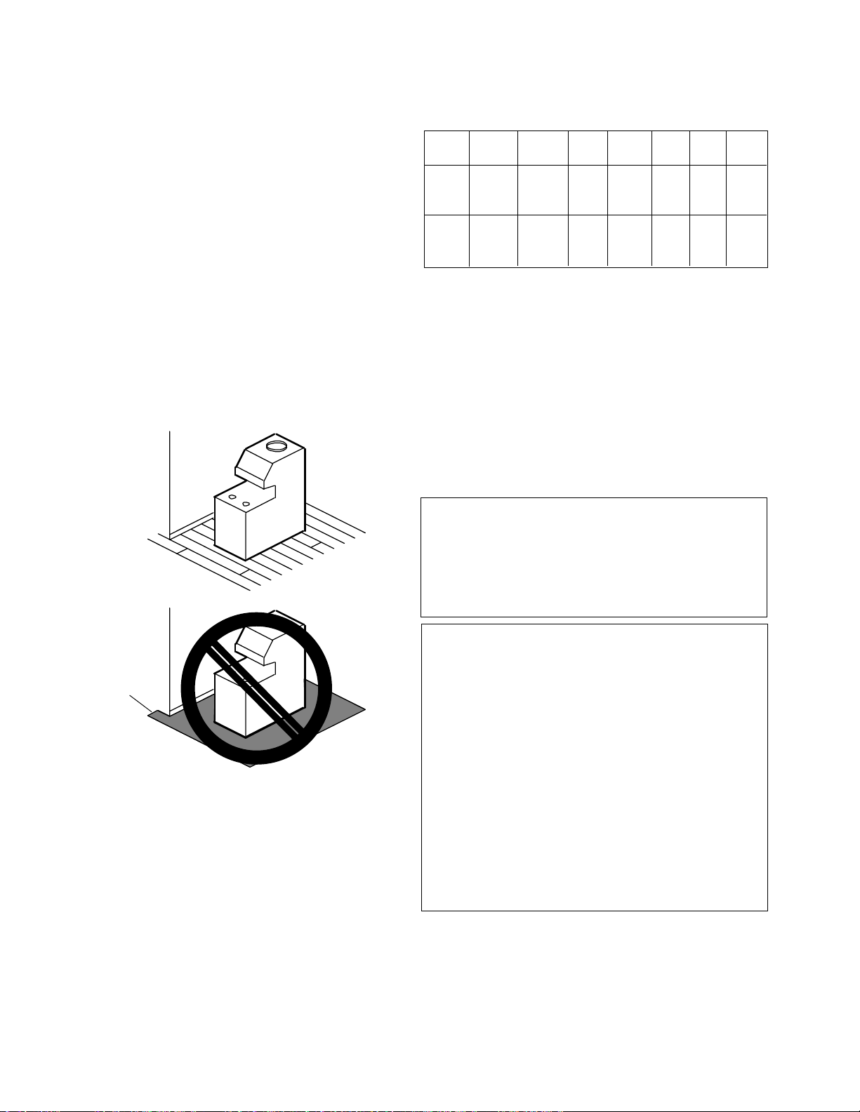
MOUNTING BASE
Boiler should be mounted on a level surface. Each
boiler is designed with a built-in sub-base approved for
mounting the boiler on combustible flooring. Boiler
must NOT be installed on carpet flooring.
CLEARANCE REQUIREMENTS
1) Minimum Clearances From Combustible Materials
Model Floor Front Back Right Left Top Flue
No. Vent
0030
0042 Comb. 4" 6" 6" 6" 16" 6"
0066
0090
0135 Comb. Alcove 6" 6" 6" 16" 6"
0180
2) A front clearance of at least 24" is recommended for
adequate service of burner-tray and controls.
3) Except for carpeted flooring, boilers are certified for
installation on combustible floors.
4) For un-insulated hot water pipes, maintain a 2"
clearance, or consult local authority having jurisdiction.
COMBUSTION/VENTILATION AIR
CARPET
CARPET
Fig.# 8196.0p
NOTE: The boiler should be located in an area where
water leakage will not result in damage to the area
adjacent to the appliance or to the structure. When
such locations cannot be avoided, it is recommended
that a suitable drain pan, adequately drained, be installed under the appliance. The pan must not restrict
air flow.
In addition, the boiler shall be installed such that
the gas ignition system components are protected from
water (dripping, spraying, rain, etc.) during appliance
operation and service (circulator replacement, control
replacement, etc.)
WARNING: Air supply to the boiler room must not be
affected by mechanical exhaust vents located in other
parts of the house, such as kitchen or bathroom fans,
or attic blowers. Mechanical exhaust vents may create
a negative pressure condition in the boiler room that
can become a hazard of asphyxiation, explosion or fire.
CAUTION: Combustion air must not be contaminated
by corrosive chemical fumes which can damage the
boiler. Measures must be taken to prevent the entry of
corrosive chemical fumes to the combustion and ventilation air supply. Such chemicals include, but are not
limited to, chlorinated and/or fluorinated hydrocarbons
such as found in refrigerants, aerosol propellants, drycleaning fluids, degreasers, and paint removers. Other
harmful elements may come from bleaches, air fresheners, or mastics. Vapors from these types of products
can form corrosive acid compounds when burned in a
gas flame. The resulting acid condensate can damage
or substantially reduce the life of the heater. It may be
necessary to provide outside air directly to the heater in
order to avoid this problem.
1) The boiler must be provided with adequate supply of
air for proper combustion and ventilation in accordance with Sec. 5.3, of the latest edition of the
National Fuel Gas Code, ANSI Z223.1, or applicable provisions of the local building codes.
4
Page 5
2) When the boiler is installed in a confined space
such as a utility room or closet (Models 0030,0042
and 0066 only), where all air is supplied from inside
the building, the boiler room must be provided with
two openings, each one having a minimum net free
area, in square inches as follows:
Model Sq. In. of Free Area
0030, 0042 & 0066 100
One opening shall be within 12 inches of the top,
and the other opening within 12 inches of the floor. If
additional gas appliances are installed in the same
space, the total input of all gas appliances installed in
the same space, must be considered in the calculation.
Refer to Sec. 5.3.5 of the latest edition of the National
Fuel Gas Code for additional requirements.
12"
Location of the openings is the same as in the
previous case - that is, within 12 inches of the top, and
within 12 inches of the bottom of the enclosure. If
horizontal ducts are used, the area must be doubled and
the duct area shall not be less than the area of the
openings they connect, and in no case shall the smallest dimension be less than 3 inches.
VENTING CONNECTIONS
These boilers have built-in drafthoods. Vent piping
the same size or larger than the draft hood outlet is
recommended; however, when the total vent height
(drafthood outlet to vent terminal) is at least ten (10)
feet, the vent pipe size may be reduced by one size only
as specified in Part 11, Note 2 and in Appendix G of the
latest edition of the National Fuel Gas Code, ANSI Z
223.1. As much as possible avoid horizontal runs of
vent pipe and too many elbows. If installation requires
horizontal runs, the vent pipe must have a minimum of
1/4 inch per foot rise and should be supported at not less
than five foot intervals. Maximum vent connector horizontal length shall be 1-1/2 feet (18 inches) for each inch
of connector diameter as follows.
12"
Fig. #8198.0
NOTE: If louvers, grills or screens are used on the
openings, obtain the net free area from their supplier or
manufacturer. If the design free area of a louver is not
known nor available, it shall be assumed that wood
louvers will have 20-25 percent free area and metal
louvers will have 60-75 percent free area as shown in
Sec. 5.3.5 National Fuel Gas Code.
3) If the boiler room is located against an outside wall
and air openings can communicate directly with the
outdoors, the two openings on the outside wall must
each have a net free area, in square inches as
follows:
Model Sq. In. Of Free Area
0030 & 0042 12
0066 18
0090 24
0135 35
0180 45
Boiler Size Vent Connector Max Horizontal
Diameter Length - FT
30 & 42 4" 6
66 & 90 5" 7.5
135 6" 9
180 7" 10.5
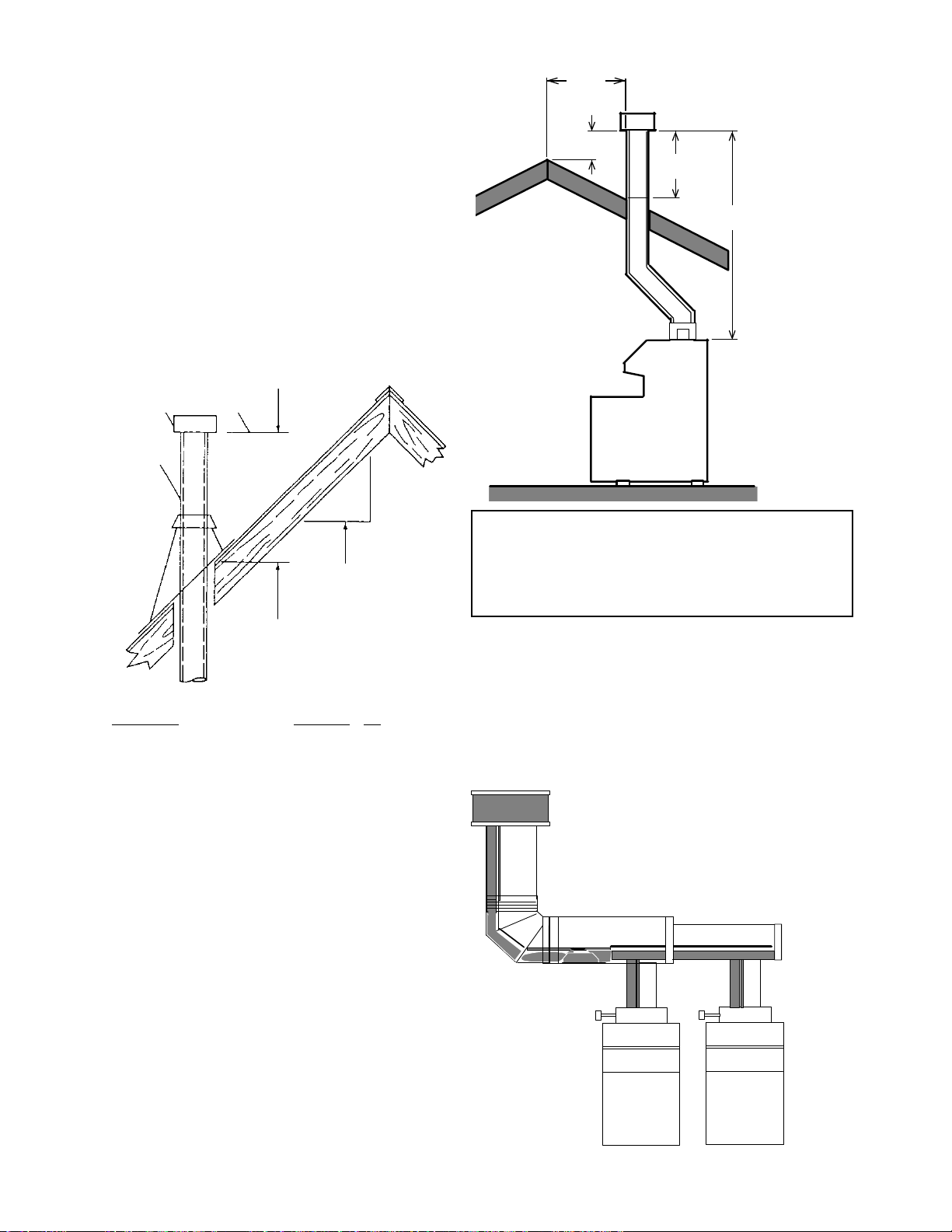
Gas Vents supported only by the flashing and
extending above the roof more than five feet should be
securely guyed or braced to withstand snow and wind
loads. We recommend use of insulated vent pipe
spacer through the roofs and walls.
For protections against rain or blockage by snow,
the vent pipe must terminate with a listed vent cap which
complies with the local codes or, in the absence of such
codes, to the latest edition of the National Fuel Gas
Code, ANSI Z 223.1.
The discharge opening must be a minimum of two
feet vertically from the roof surface and at least two (2)
feet higher than any part of the building within ten (10)
feet. Vent stack shall be at least five (5) feet in vertical
height above the drafthood outlet. The vent cap location
shall have a minimum clearance of four (4) feet horizontally from, and in no case above or below, unless a 4-foot
horizontal distance is maintained, from electric meters,
gas meters regulators and relief equipment.
5
Page 6
The weight of the vent stack or chimney must not
rest on boiler draft hood. Support must be provided in
compliance with applicable codes. The boiler top and
draft hood must be readily removable for maintenance
and inspection. Vent pipe should be adequately supported to maintain proper clearances from combustible
construction.
Type "B" double wall (or equivalent vent pipe is
recommended. However single wall metal vent pipe
may be used as specified in the latest edition of the
National Flue Gas Code ANSI Z 223.1.
Lowest Discharge
Listed Cap
Listed Gas Vent
Opening
10’
OR LESS
2’ MIN.
VENT CAP
2’ MIN.
5’ MIN.
12
Roof Pitch is X/12
H (Min.)-Minimum Height from
Roof to Lowest
Discharge Opening
Roof Pitch H (Min.) Ft.
Flat to 6/12 1.0
6/12 to 7/12 1.25
Over 7/12 to 8/12 1.5
Over 8/12 to 9/12 2.0
Over 9/12 to 10/12 2.5
Over 10/12 to 11/12 3.25
Over 11/12 to 12/12 4.0
Over 12/12 to 14/12 5.0
Over 14/12 to 16/12 6.0
Over 16/12 to 18/12 7.0
Over 18/12 to 20/12 7.5
Over 20/12 to 21/12 8.0
X
Fig.# 8191.0
WARNING: These boilers must not be connected into
any portion of mechanical draft systems operating
under positive pressure. To do so may cause the flue
products to be discharged into the living space causing
serious health injury.
For connections to gas vents or chimneys, vent
installations shall be in accordance with Part 7, Venting
of Equipment, of the National Fuel Gas Code, ANSI
Z223.1, or applicable provisions of the local building
codes.
COMMON VENTS
Manifolds that connect more than one
boiler to a common chimney must be
sized to handle the combined load.
Consult available guides for proper
sizing of the manifold and the chimney.
At no time should the area be less than
the area of the largest outlet.
Fig. #9001
6
Page 7
At the time of removal of an existing boiler, the
following steps shall be followed with each appliance
remaining connected to the common venting system
placed in operation, while the other appliances remaining connected to the common venting system are not
in operation.
(a) Seal any unused openings in the common venting
system.
(b) Visually inspect the venting system for proper size
and horizontal pitch and determine there is no
blockage or restriction, leakage, corrosion and
other deficiencies which could cause an unsafe
condition.
(c) Insofar as is practical, close all building doors and
windows and all doors between the space in which
the appliances remaining connected to the com-
mon venting system are located and other spaces
of the building. Turn on clothes dryers and any
appliance not connected to the common venting
system. Turn on any exhaust fans, such as range
hoods and bathroom exhausts, so they will operate
at maximum speed. Do not operate a summer
exhaust fan. Close fireplace dampers.
(d) Place in operation the appliance being inspected.
Follow the lighting instructions. Adjust thermostat
so appliance will operate continuously.
e) Test for spillage at the draft hood relief opening
after 5 minutes of main burner operation. Use the
flame of a match or candle, or smoke from a
cigarette, cigar or pipe to visually check spillage.
(f) After it has been determined that each appliance
remaining connected to the common venting sys-
tem properly vents when tested as outlined above,
return doors, windows, exhaust fans, fireplace
dampers and any other gas burning appliance to
their previous conditions of use.
(g) Any improper operation of the common venting
system should be corrected so the installation
conforms with the latest edition of the National Fuel
Gas Code, ANSI Z 223.1. When resizing any
portion of the common venting system, the com-
mon venting system should be resized to ap-
proach the minimum size as determined using the
appropriate tables in Part 11 and in Appendix G
of the National Fuel Gas Code, ANSI Z 223.1 and
CAN/CGA - B149.1 - M91.
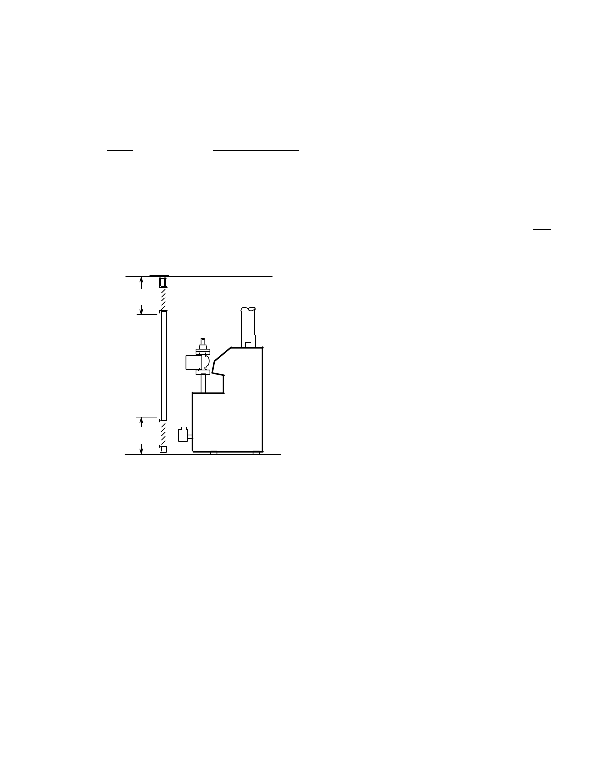
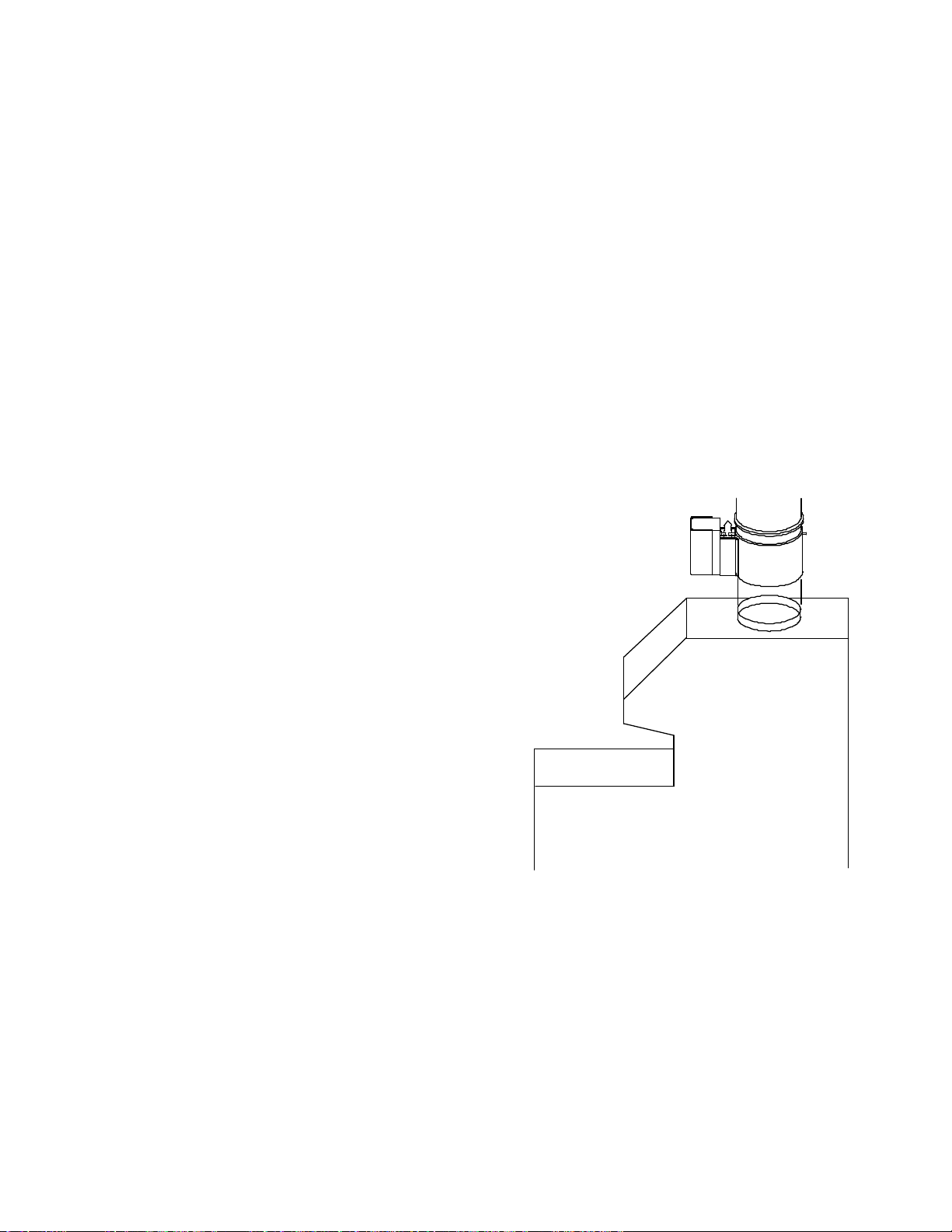
VENT DAMPER INSTALLATION
LOCATION
The vent damper supplied with each boiler must be
located in the vent so that it serves only the appliance
for which it is intended.
If improperly installed, a hazardous condition,
such as an explosion or carbon monoxide poisoning, could result. Make certain that it is mounted in an
accessible location at least 6 in. (152.4 mm) from any
combustible material or the heat exchanger and that
the position indicator is in a visible location.
The vent damper must be installed at the appli-
ance draft hood, and without modification of the draft
hood.
To connect the vent damper wiring to the boiler wiring,
remove the jumper from the circuit plug. (See wiring
diagram) Connect the damper circuit plug to the boiler
circuit plug.
Fig. #8642
7
Page 8
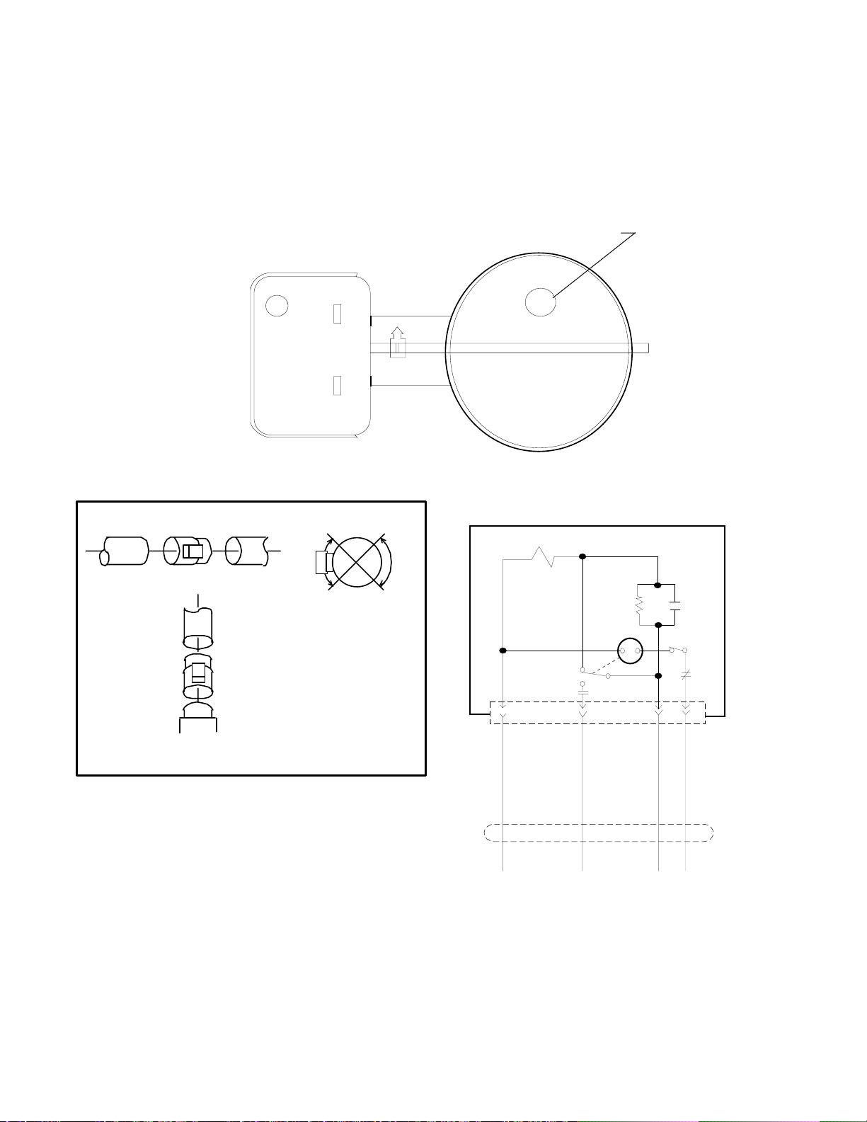
MOUNTING
On vertical vents, the vent damper may be mounted with the actuator in any position. On horizontal vents,
do not mount the actuator either directly above or directly below the vent pipe; mount the vent damper actuator
to the side of the vent.
The vent damper is set up for a continuous pilot system. If the vent damper is installed on an Intermittent Pilot
or Hot Surface Ignition equipped system, the energy savings of the vent damper can be improved by plugging the
hole in the vent damper blade using the knockout plug, Part No. 105612R, provided in the parts envelope.
Hole in Vent Damper Blade
Closed Position
Fig. #8994
DO NOT plug the hole if installing the vent damper on a continuous pilot system as this will create a
hazardous condition.
HORIZONTAL INSTALLATION
FLOW >
TO BOILER VENT DAMPER
VERTICAL
INSTALLATION
TO CHIMNEY
TO CHIMNEY
VENT
DAMPER
AT BOILER
DRAFT
HOOD
YES
INSTALL VENT
DAMPER WITH
ACTUATOR TO SIDES
OF VENT ONLY. DO
NOT MOUNT ABOVE OR
BELOW VENT.
ACTUATOR MAY BE
INSTALLED IN ANY
POSITION ON VERTICAL
PIPE.
NO
YES
NO
Fig. #8183.0
INSTALLING THE VENT DAMPER IN HORIZONTAL
& VERTICAL VENTS.
1K
1K1
D80
MOTOR
END
SWITCH
4
YELLOW
N.C.
N.O.
C.
1K3
32
BLUE
BLACK
1K2
1
ORANGE
D80D GENERAL WIRING DIAGRAM
CABLE
Fig. #152323
INSTALL THE VENT DAMPER TO SERVICE ONLY THE SINGLE APPLIANCE FOR WHICH IT IS INTENDED.
IF IMPROPERLY INSTALLED, A HAZARDOUS CONDITION, SUCH AS AN EXPLOSION OR CARBON
MONOXIDE POISONING, COULD RESULT.
8
Page 9

VENT DAMPER
R
2
4
3
J
SS
HL
GV
1
ES
R
2
SC
M
24 V AC
R
1
SS
2
TH
NORMAL OPERATION SUMMARY
For safe, efficient operation, the vent damper and all flue product carrying areas of the appliance must
be checked annually, with particular attention given to deterioration from corrosion or other sources.
Check vent damper operation as follows:
1. When the boiler is off, check that the vent damper position indicator points to the closed position, below.
DAMPER
POSITION
INDICATOR
DAMPER
POSITION
INDICATOR
NOTE: To place vent damper in
the open position to allow burner
operation do the following:
Turn the power off, turn the damper
blade to fully open position (arrow
facing same direction as vent
pipe). Turn power on.
Fig. # 8181.0
DAMPER OPEN DAMPER CLOSED
FIG. 4- VENT DAMPER POSITION INDICATOR SHOWING OPEN & CLOSED POSITIONS.
2. Turn the thermostat or controller up to call for heat and check that the vent damper indicator points to the
open position, below.
3. Turn the thermostat or controller down again and check that the vent damper position indicator returns to
the closed position.
THE VENT DAMPER MUST BE INSPECTED AT LEAST ONCE A YEAR BY A TRAINED, EXPERIENCED
SERVICE TECHNICIAN. THE NAME OF THE PERSON WHO ORIGINALLY INSTALLED YOUR VENT
DAMPER IS SHOWN ON THE INSTALLATION LABEL. DAMPER MUST BE IN OPEN POSITION WHEN
BOILER MAIN BURNERS ARE OPERATING.
FLAIR DAMPER
SYSTEM SCHEMATIC LEGEND LADDER DIAGRAM
M - Damper motor
R - Relay
R
R
SS
2
SC
R
1
M
2
HL
TR
L
GV
24 VAC
120 VAC
60Hz
L
12
ES
2
SS
1
JUMPER
3
TH
41
Fig. #9002 Fig. #9003
ES - End Switch
SS1 - N/C Safety switch
SS2 - N/O Safety switch
contacts
TR - Transformer 120/24V
HL - High limit
GV - 24V gas Valve*
TH - Thermostat, heating,
low voltage
J - Jumper
* Note: Circuit shown with
damper in closed
position, no call
for heat.
9
Page 10
GAS SUPPLY CONNECTIONS
The inlet gas connection of the boiler gas valve is
1/2". Provide an adequate gas piping supply line no
smaller than 1/2", according to the chart below:
The gas valve is provided with pressure taps to
measure gas pressure upstream of the gas valve and
downstream which is the same as the manifold pressure.
Maximum Equivalent Pipe Length (Feet)
1/2" Pipe 3/4" Pipe 1" Pipe 1 1/4" Pipe
MODEL NAT PRO NAT PRO NAT PRO NAT PRO
0030 &
0042
0066 60 160 175 460 - - - 0090 30 80 125 325 400 - - 0135 15 40 60 155 200 500 - 0180 - 20 35 90 115 300 425 -
125 350 500 - - - - -
Gas piping must have a sediment trap ahead of the
boiler gas controls, and a manual shutoff valve located
outside the jacket. All gas piping should be tested after
installation in accordance with local codes.
Manual Union
Valve
Sediment Trap Gas Valve
Fig. # 8192.0
CAUTION: The boiler and its manual shut off valve must
be disconnected from the gas supply during any pressure testing of that system at test pressures in excess
of 1/2 psig (3.45 KPA). Dissipate test pressure in the
gas supply line before reconnecting the boiler and its
manual shut off valve to gas supply line. FAILURE TO
FOLLOW THIS PROCEDURE MAY DAMAGE THE
GAS VALVE. OVER PRESSURED GAS VALVES ARE
NOT COVERED BY WARRANTY. The boiler and its
gas connections shall be leak tested before placing the
appliance in operation. Use soapy water for leak test.
DO NOT use open flame.
NOTE: Do not use teflon tape on gas line pipe thread.
A flexible sealant suitable for use with Natural and
Propane gases is recommended.
GAS PRESSURE-SPECIFICATIONS
Inches W.C. Regulator
Min. Max. Setting
Natural 7.0 14.0 3.5
Propane 12.0 14.0 11.0
WATER CONNECTIONS & SYSTEM PIPING
The pipe size for water connections is shown on
page 3. Typical piping systems are shown on pages 11
to 13.
The boiler is supplied as standard with a circulator
and a built -in by-pass to insure the required minimum
water flow in the boiler. The by-pass on models H-0135
and H-0180 is provided with an adjustable valve that is
factory set in the full open position. The handle is
shipped loose. The full open position is appropriate for
most systems, and insures adequate flow through the
boiler. If system flow is inadequate, (indicated by
excessive temperature drop through the system) the bypass valve can be throttled slightly. Care must be taken
against over throttling which may lead to inadequate
flow through the boiler and boiler harmonics (a humming
sound from the heat exchanger). If adequate system
flow cannot be obtained without causing harmonics, an
additional pump is required. The factory mounted
circulator will provide adequate water flow for systems
designed at a 20°F temperature drop, and system
pressure drop or head not exceeding that is shown
below.
System Maximum
Models Flow System Head
(GPM) (Ft/Wtr)
H-0030 2.5 9.0
H-0042 3.5 8.0
H-0066 5.3 8.5
H-0090 7.3 6.5
H-0135 11.0 10.0
H-0180 14.6 7.0
When the total system head exceeds the available
head pressures, a primary/secondary pumping system
is recommended.
The minimum boiler operating temperature
should be 105°F. When operating at low temperature applications, ÐT (temperature rise) must be
20°F or less.
Propylene glycol solution is commonly used in the
heating system when freeze protection is required. This
will affect the system design and pump performance. As
a "rule of thumb", 50% solution of propylene glycol will
require the system flow (GPM) to increase by 14%, and
the system head (Ft/Wtr) by 23% in order to maintain the
same heat transfer load.
10
Page 11

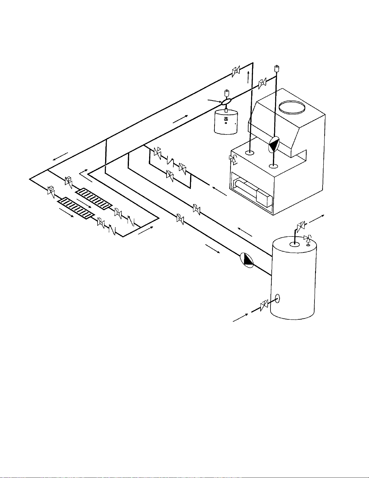
Systems with multiple zones may require an additional circulator. Consult manufacturers data for valve
pressure drops. When an indirect water heating system is used, it is recommended that a separate circulator be
installed to meet the required flow and pressure drop conditions of the indirect water heater.
We recommend that the make up water from the cold water line have a check valve, gate valve, and feedwater
regulator set at 12 psig. Install unions and gate or ball valves at inlet and outlet connections at the boiler to facilitate
servicing.
The pressure relief valve is mounted on the boiler and must be piped to a drain. We recommend that all high
points be vented and that purge valves be installed. A boiler installed above radiation level must be provided with
a low water cutoff device. See page 21 for wiring hook-up. The boiler, when used in connection with a refrigeration
system, must be installed so the chilled medium is piped in parallel with the boiler with appropriate valves to prevent
the chilled medium from entering the boiler.
The boiler piping system of a hot water heating boiler connected to heating coils located in air handling units
where they may be exposed to refrigerated air circulation must be equipped with flow control valves or other
automatic means to prevent gravity circulation of the boiler water during the cooling cycle.
A diaphragm expansion tank should be installed in the return line. A typical 8" diameter expansion tank can
be used on the models H-0030, H-0042, and H-0066 and an 11" diameter expansion tank can be used on the
model H-0090, H-0135 and H-1080. Consult tank manufacturer for correct sizing.
TYPICAL PIPING
AIR
VENT
HEATING UNITS
SINGLE ZONE PIPING
AIR
SCOOP
DIAPHRAGM
EXPANSION TANK
FEED
VALVE
PIPE PRESSURE
RELIEF VALVE
TO DRAIN
COLD
WATER
INLET
Fig.# 8997.1
11
Page 12
FEED
VALVE
AIR
VENT
AIR
SCOOP
DIAPHRAGM
EXPANSION
TANK
PIPE PRESSURE
RELIEF VALVE
TO DRAIN
ZONE
VALVES
HEATING UNITS
COLD
WATER
INLET
CIRCULATOR
COLD
WATER
SUPPLY
HOT WATER
SUPPLY
ZONE HEATING WITH INDIRECT DOMESTIC
HOT WATER SUPPLY
Fig.# 8998.1
12
Page 13

FEED
VALVE
AIR
SCOOP
DIAPHRAGM
EXPANSION
TANK
PIPE PRESSURE
RELIEF VALVE
TO DRAIN
AIR
VENT
12" MAX.
CIRCULATORS
HEATING UNITS
COLD
WATER
INLET
MULTIPLE ZONES WITH CIRCULATORS Fig. #8999.1
AIR
VENT
AIR
SCOOP
DIAPHRAGM
EXPANSION
FEED
VALVE
TANK
PIPE PRESSURE
RELIEF VALVE
TO DRAIN
COLD
ZONE
VALVES
HEATING UNITS
WATER
INLET
MULTIPLE ZONES WITH ZONE VALVES Fig. #9000.1
13
Page 14

ELECTRICAL WIRING
The electrical power supply requirement for these
boilers is 115 volts, 60 Hz. Field wiring connections and
electrical grounding must comply with the local codes,
or in the absence of local codes, with the National
Electrical Code, ANSI/NFPA 70-1987. Provide a separate fused circuit from the main electrical panel to the
boiler, and a disconnecting means within sight of the
boiler.
Remove the control box cover and make the power
supply connections in the field wiring compartment.
(See general location of controls drawing on page 18).
The pump is supplied and factory wired to operate with
the boiler. The "TH" wire leads are for the room
thermostat or zone valve connections.
WIRING DIAGRAM KEY
The room thermostat should be installed in accordance
with the manufacturer's instructions. The thermostat
heat anticipator should be set at 1.0 ampere (automatic
ignition) and 0.60 ampere (standing pilot) for single
zone installations. For multi-zone applications, the heat
anticipator setting should be based on the ampere load
in the thermostat circuit.
NOTE: If it is necessary to replace any of the original
wiring, it must be replaced with 105°C wire or its
equivalent, except 150° black wire must be replaced
with 150°C wire or its equivalent. See wiring diagram
key for 150°C wire indication.
14
Fig.# 8096.2
Page 15

WIRING DIAGRAM: STANDING PILOT 24 V 2 STAGE
MODELS 90, 135 & 180
Fig. # 2223e
See page 14 wiring diagram key information.
15
Page 16

WIRING DIAGRAM:INTERMITTENT IGNITION DEVICE (IID)
MODELS 30, 42, & 66
*REFER TO INSTALLATION/OPERATING INSTRUCTIONS
AND WIRING DIAGRAM SUPPLIED WITH VENT DAMPER.
VENT DAMPER OPTIONAL ON CANADIAN MODELS.
See page 14 wiring diagram key information.
16
Page 17

WIRING DIAGRAM: INTERMITTENT IGNITION DEVICE (IID)
MODELS 90, 135 & 180
*REFER TO INSTALLATION/OPERATING INSTRUCTIONS
AND WIRING DIAGRAM SUPPLIED WITH VENT DAMPER.
VENT DAMPER OPTIONAL ON CANADIAN MODELS.
See page 14 wiring diagram key information.
Fig. #2358
17
Page 18

WIRING DIAGRAM: Single Zone Taco Valve
WIRING DIAGRAM: Dual Zone Taco Valve
Fig. # 2228e
NOTE: Maximum three (3) zone valves per one (1) 40 VA transformer.
WIRING DIAGRAM: Dual Zone Honeywell Valve
NOTE: Maximum five (5) zone valves per one (1) 40 VA Transformer.
18
Fig. # 2229e
Fig. # 2230e
Page 19

WIRING DIAGRAM: System with (3) Zone Pumps
NOTE: Check VA rating of each relay coil. Total load must not exceed VA rating of transformer.
WIRING DIAGRAM: Power Vent System w/ Zone Valve
Taco Zone Valve
Fig. #2232e
Honeywell Zone Valve
Fig. #2233e
Fig. #2234e
19
Page 20

WIRING DIAGRAM: Primary/Secondary Pumping System
Honeywell Zone Valve
20
Fig. #2223.2e
Page 21

WIRING DIAGRAM: Standing Pilot With Low Water Cut Off Device
Fig. # 2223.1e
Note: Low water cut off (LWCO) and system switch supplied by others.
WIRING DIAGRAM: IID Units With Low Water Cut Off Device
Note: Low water cut off (LWCO) and system switch supplied by others.
21
Fig. # 2357E
Page 22

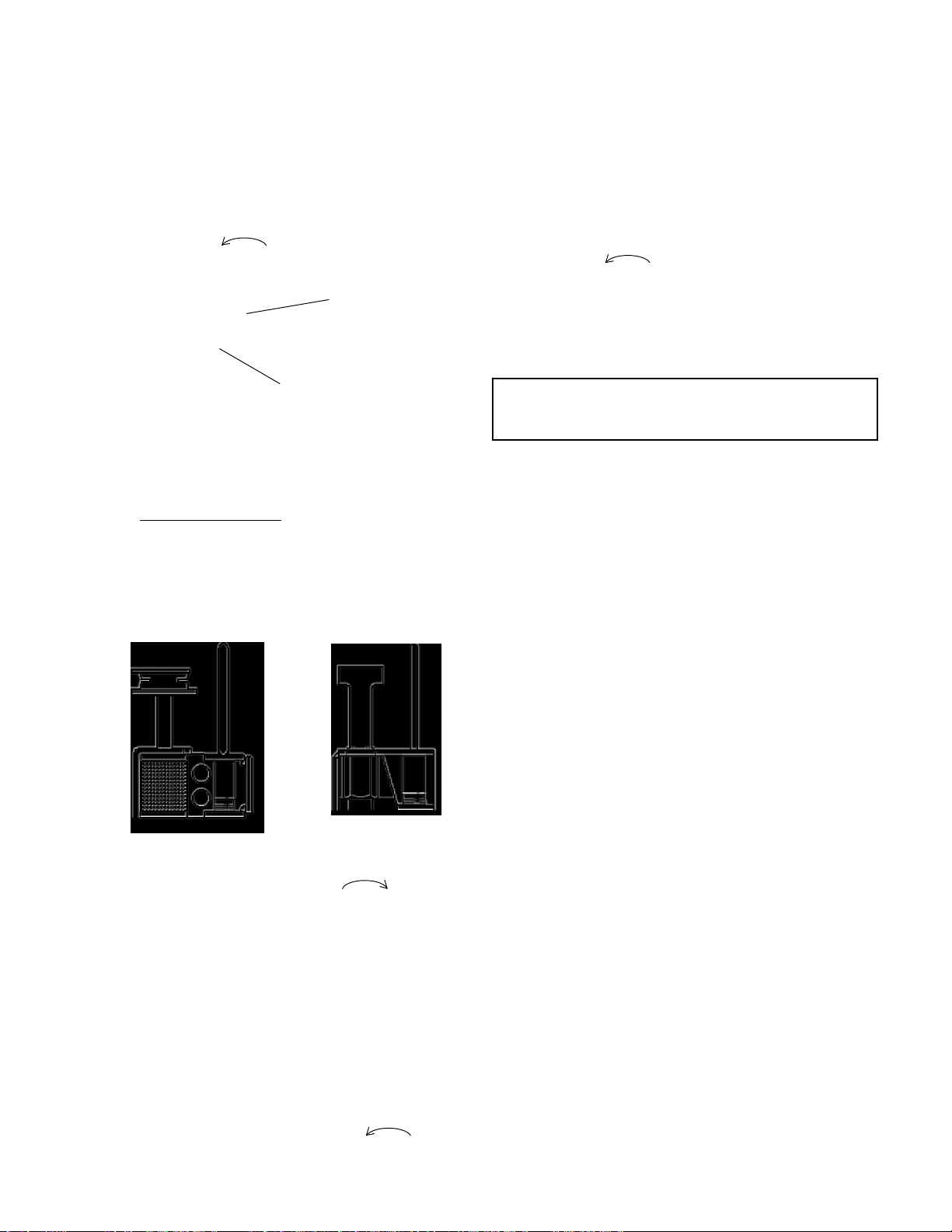
4. SERVICING PROCEDURES
GENERAL LOCATION OF CONTROLS
CONTROL BOX COMPONENT
LOCATIONS MODELS 135 & 180
2-Staged Controller
Relay
Fast
Response
Temperature
Sensor
Ignition Module
(Auto Ignition Only)
Fig.# 8195.1
CIRCULATOR
VENT SENSOR
BYP ASS VALVE
(MODELS 135 & 180 ONLY)
BYPASS LINE
TEMPERATURE
AND PRESSURE GAUGE
2-STAGED CONTROLLER
(MODEL 90 ONLY)
PRESSURE
RELIEF VALVE
RELA Y
ADJUST ABLE
HIGH LIMIT
FIELD WIRING
COMP AR TMENT
FAST RESPONSE
TEMPERATURE SENSOR
IGNITION MODULE
(AUTO IGNITION ONLY)
TRANSFORMER
ROLL-OUT SENSOR
GAS VALVE
Fig.# 8195.4
SEQUENCE OF OPERATION
INTERMITTENT IGNITION DEVICE (IID)
Boilers equipped with the IID system will automatically light the pilot burner first and then the main burner, each
time there is a call for heat from the room thermostat. Whenever the room thermostat is calling for heat, the
circulator supplied with the boiler, will be energized and should be running. The ignition control module will also
be energized to initiate the pilot ignition by opening the first main valve (pilot). At the same time, the electronic
spark generator in the module produces a high voltage spark pulse output that lights the pilot burner. If the pilot
burner does not light, the module will not energize the second main valve and the burners will not light. Ignition
spark continues only until the timed trial for ignition period ends. Then, the module goes into safety shutdown or
lockout. Lockout de-energizes the first main valve operator and closes the first main (pilot) valve in the gas control,
stopping pilot gas flow. The ignition control system must be reset by setting the thermostat below room
temperature for one minute or by turning off power to the module for one minute. When the pilot flame is
established, flame rectification circuit is completed between the sensor and burner ground. The flame sensing
circuit in the module detects the flame current, shuts off the spark generator and energizes the second main valve
operator which opens the second main valve. This allows gas to flow to the burners where it is ignited by the pilot
burner flame. When the thermostat is satisfied, the valve operators are de-energized shutting off the pilot and main
burners, and also the circulator.
22
Page 23

START-UP PROCEDURES
SECTION 1. Filling the System
Fill system with water. Purge all air from the system
using purge valve sequence. After system is purged of
air, lower system pressure. Open valves for normal
system operation, fill system through feed pressure
regulator to minimum 12 PSI. Manually open air vent
on the compression tank until water appears, then close
vent.
On multiple zone systems, purge each zone separately. Isolate the other zones while one zone is being
purged of air.
Flush system before putting into operation to assure that foreign material does not damage pump seals.
SECTION 2. Checking the Circulator
Before lighting the boiler and after system is filled,
make sure that circulator is operating properly. Manual
gas valve should be off. By adjusting the wall thermostat to the maximum setting, circulator should run
immediately and allow water to flow through the boiler
and the entire system.
NOTE: Circulator motor supplied with the boiler does
not require lubrication.
CAUTION: In case of a prolonged power failure during
freezing weather conditions, boiler and piping system
must be drained completely to avoid possible damage
to the heating system.
23
Page 24

SECTION 3. Lighting the Boiler
Safe lighting and other performance criteria were
met with the gas manifold and control assembly provided on the boiler when the boiler underwent tests
specified in ANSI-Z21.13a 1983 Standard.
CAUTION: Liquefied petroleum gas is heavier than air
and sinks to the ground. Exercise extreme care in
lighting boiler in confined areas.
For Standing Pilot Models
WARNING: If you do not follow these instructions
exactly, a fire or explosion may result causing property
damage, personal injury or loss of life.
A. This boiler has a pilot which must be lighted by
hand. When lighting the pilot, follow these instructions
exactly.
B. BEFORE LIGHTING Smell all around the boiler
area for gas. Be sure to smell next to the floor because
some gas is heavier than air and will settle on the floor.
WHAT TO DO IF YOU SMELL GAS
Do not try to light any appliance.
Do not touch any electric switch;
Do not use any phone in your building.
Immediately call your gas supplier from a
neighbor's phone. Follow the gas supplier's
instructions.
If you cannot reach your gas supplier, call the
fire department.
C. Use only your hand to push in, move or turn the gas
control knob or lever. Never use tools. If the knob or
lever will not push in, move or turn by hand, don't try to
repair it, call a qualified service technician. Force or
attempted repair may result in a fire or explosion.
D. Do not use this boiler if any part has been under water.
Immediately call a qualified service technician to inspect
the boiler and to replace any part of the control system
and any gas control which has been under water.
24
Page 25
FOR STANDING PILOT MODELS WITH ROBERT-
SHAW GAS VALVE, 2 STAGE OPERATION
(Models 90, 135 & 180)
1. STOP! Read the safety information.
2. Set the thermostat to the lowest setting.
3. Turn off all electric power to the boiler.
4. Push in and move gas control lever counterclockwise to "OFF" position.
GAS CONTROL
LEVER SHOWN
IN "OFF" POSITION
GAS INLET
Fig. #8934.0
10. Turn on all electric power to the boiler.
11. Set the thermostat to the desired setting.
TO TURN OFF GAS TO THE BOILER:
(Models 90, 135 & 180)
1. Set the thermostat to the lowest setting.
2. Turn off all electric power to the boiler
3. Push in and move gas control lever counterclockwise to "OFF" position. Do not force.
FOR AUTOMATIC IGNITION MODELS.
Please read carefully and understand the following
safety information before operating the boiler.
WARNING: If you do not follow these instructions
exactly, a fire or explosion may result causing property
damage, personal injury or loss of life.
NOTE: Lever cannot be moved from "ON" to
"OFF" unless lever is pushed in slightly. Do not
force.
5. Wait five (5) minutes to clear out any gas. Then
smell for gas, including near the floor. If you smell
gas, STOP! Follow "B" in the safety information
above on this label. If you don't smell gas, go to the
next step.
6. Locate pilot mounted on the right side of the
burner drawer, and right of first burner.
Fig.# 8083.2
Fig.# 8041.2
HONEYWELL PILOT ROBERTSHAW PILOT
7. Move control lever clockwise to "SET"
position and immediately light pilot with a match.
8. Hold lever in "SET" position for 1/2 minute after
pilot is lit. Release lever, and it will spring back
to "PILOT" position. Pilot should remain lit. If it
goes out, repeat steps 4 through 8.
*If lever does not spring back to "PILOT" position
when released, stop and immediately call your
service technician or gas supplier.
*If the pilot does not stay lit after several tries,
move the gas control lever to "OFF" and call your
service technician or gas supplier.
9. Stand to the side of the boiler and move the gas
control lever counter-clockwise to "ON".
A. This boiler is equipped with an ignition device which
automatically lights the pilot. Do not try to light the pilot
by hand; or this boiler may not have a pilot and is
equipped with a hot surface ignition device which automatically lights the burners. Do not try to light the
burners by hand.
B. BEFORE OPERATING smell all around the boiler
area for gas. Be sure to smell next to the floor because
some gases are heavier than air and will settle on the
floor.
WHAT TO DO IF YOU SMELL GAS
Do not try to light any appliance.
Do not touch any electric switch;
Do not use any phone in your building.
Immediately call your gas supplier from a
neighbor's phone. Follow the gas supplier's
instructions.
If you cannot reach your gas supplier, call the
fire department.
C. Use only your hand to push in, move or turn the gas
control knob or lever. Never use tools. If the knob or
lever will not push in, move or turn by hand don't try to
repair it, call a qualified service technician. Force or
attempted repair may result in a fire or explosion.
D. Do not use this boiler if any part has been underwater. Immediately call a qualified service technician to
inspect the boiler and to replace any part of the control
system and any gas control which has been underwater.
25
Page 26

FOR INTERMITTENT IGNITION (IID) WITH HONEYWELL OR ROBERTSHAW GAS VALVE (For All Models)
1. STOP! Read the safety information above.
2. Set the thermostat to the lowest setting.
3. Turn off all electric power to the appliance.
4. This boiler is equipped with an ignition device which
automatically lights the pilot. Do not try to light the
pilot by hand.
GAS CONTROL
KNOB SHOWN
IN "ON"
POSITION
TO TURN OFF GAS TO BOILER
1. Set the thermostat at the lowest setting.
2. Turn off all the electric power to the boiler if service
is to be performed.
3. For Honeywell Valve:
Turn gas control knob clockwise to
"Off". Make sure knob rest against stop.
For Robertshaw Valve:
Push in and move gas control lever to "Off"
position.
GAS INLET
Fig. #8201.0
HONEYWELL
(Models 30 - 90)
5. For Honeywell Valve: Turn gas control knob
clockwise to "Off".
For Robertshaw Valve: Push in and move gas
control lever to "Off" position.
6. Wait 5 minutes to clear out any gas. Then smell for
gas, including near the floor. If you smell gas,
STOP! Follow "B" in the safety information above
on this label. If you don't smell gas, go to the next
step.
7. For Honeywell Valve: turn gas control counter-
clockwise to "On".
For Robertshaw Valve: Move gas control lever
to "On" position.
GAS CONTROL
KNOB SHOWN
IN "OFF"
POSITION
GAS INLET
Fig. #8199.0
ROBERTSHAW
(All Models)
HONEYWELL PILOT
SYSTEM SHUT DOWN PROCEDURE
To prevent the potential freezing damage to the
heating system, it is recommended that the following
system shut down procedure be performed.
1. Set the room thermostat to "OFF" or the lowest
setting.
2. Turn off all electric switches to the boiler.
3. Turn off all gas valves supplying gas to the boiler.
Refer to operating instruction label on the boiler.
4. Shut off the water supply to the boiler piping system
loop.
5. Open drain valve on the boiler to remove water from
the boiler and the piping circuits.
Note: It may be necessary to open the purge valves and/
or manual air vents to facilitate complete drainage of
water from the heating system.
8. Turn on all electric power to the boiler.
9. Set thermostat to desired setting.
10. If the boiler will not operate, follow the instruction
"To Turn Off Gas To Boiler" and call your service
technician or gas supplier.
26
Page 27

CAUTION: Should overheating occur or the gas supply
fails to shut off, DO NOT turn off or disconnect the
electrical supply to the pump. Instead, shut off the gas
supply at a location external to the boiler. Failure to
observe this precaution may aggravate the overheated
condition resulting in possible damage to the boiler and
injury to the user.
SECTION 4. Testing the Ignition Safety Shutoff.
The ignition system safety shutoff must be tested by
conducting the following method of tests:
For Standing Pilot Systems
a. With the main burners on, remove the pilot
adjustment cover screw.
* NOTE: There is no pilot adjustment cover on
Robertshaw 7200 gas valve.
b. Insert a small slot screw driver and turn the
adjustment screw clockwise until pilot
flame goes out. Note and count number of turns
made.
c. Gas valve will shut off main burners after about
three (3) minutes. End of test. If the gas valve
will not shut off, follow the instructions "To Turn
Off Gas To Boiler" and call service technician or
your gas supplier.
d. Return pilot adjustment screw counter-clock-
wise , same number of turns as in step (b).
FOR AUTOMATIC IGNITION SYSTEMS
Intermittent Ignition (IID)
1. Turn on power to the ignition systems and turn gas
supply off at the gas valve.
2. Check ignition module as follows:
a. Set the thermostat or controller above room
temperature to call for heat.
b. Watch for continuous spark at the pilot burner.
c. Time the spark operation. Time must be within
the lockout timing period (15 or 90 seconds).
d. Turn thermostat down to end call for heat and
wait 60 seconds on lockout models before
beginning step 3.
3. Turn on gas supply.
4. Set thermostat or controller above room temperature to call for heat.
5. Systems should start as follows:
a. Spark will turn on and pilot gas valve will open
at once. Pilot burner should ignite after gas
reaches the pilot burner.
b. Spark ignition should cut off when pilot flame is
established.
c. Main gas valve should open and main burner
should ignite after gas reaches the burner port.
3
O
F
F
Fig.# 8935.0
ROBERTSHAW 7200 GAS VALVE
(Models 90, 135 & 180)
1
2
PILOT
ADJ
P
LOT
I
SET
Pilot Adjustment
O
N
e. Replace pilot adjustment cover screw, then
follow the lighting instructions to get boiler
ready for operation.
27
Page 28

SAFE SHUTDOWN TESTS
LIMIT ACTION
With the burner operating, lower the high limit
setting to simulate an overheated boiler. Normal shutdown should occur. Restore the normal limit setting,
and the burner should restart.
FLAME FAILURE
With burner operating, close the manual fuel valves
to simulate a flame failure. System should lock out after
safety switch timing (15 seconds). After the safety
switch has cooled, open the manual valves (relight
standing pilots) and reset the safety switch; the burner
should restart.
INSPECTION PROCEDURES
BURNERS
Clean main burners and air louvers of dust, lint and
debris. Keep boiler area clear and free from combustibles and flammable liquids. Do not obstruct the flow of
combustion and ventilating air. Make visual check of
burner and pilot flame. Yellow flame indicates clogging
of air openings. Lifting or blowing flame indicates high
gas pressure. Low flame indicates low gas pressure.
4"
Max.
Fig. #8964
PILOT BURNER FLAME (STG PILOT UNITS)
NORMAL INSPECTION PROCEDURES
First and third month after initial start up and then on
an annual basis. If problems are found, refer to Trouble
Shooting Guide for additional directions.
1. Remove top of boiler and inspect heat exchanger
for soot and examine venting system.
2. Remove rear header and inspect for scale depos-
its.
*3. Inspect pilot and main burner flame and firing rate.
*4. Inspect and operate all controls and gas valve.
*5. Visually inspect system for water leaks.
*6. Oil pump motor and bearing assembly, if oil cups
are provided.
7. Check flow switch paddle.
8. Clean room air intake openings to assure adequate
flow of combustion and ventilation air.
9. Keep boiler area clear and free from combustible
materials, gasoline, and other flammable vapors
and liquids.
*Should be checked monthly. (Takes approximately 15
minutes).
Fig. #8144
MAIN BURNER FLAME
NOTE: Modulating burner flame varies in height from
approximately 1/4" at low fire to approximately 4" in
high fire.
28
Page 29

LOW WATER CUT OFF WHEN INSTALLED
The low water cut off automatically shuts down
burner whenever water level drops below probe. 90
second time delay prevents premature lockout due to
temporary conditions such as power failure or air pockets. Flush float type devices at beginning of each
heating season.
PROCEDURE FOR CLEANING FLUE GAS
PASSAGE-WAYS
Soot will clog areas behind fins and cause eventual
tube failure. Any sign of soot at base of burners or
around outer jacket indicates a need for cleaning.
1. Lift off draft hood and flue collector by removing
bolts and screws.
2. Remove "V" baffles from heat exchanger.
3. Remove burner tray, see Burner Drawer Removal.
4. Take garden hose and wash heat exchanger, mak-
ing sure soot is removed from between fins.
(Avoid excessive water against refractory).
5. Reassemble; when boiler is fired, some steam will
form from wet refractory. This is normal.
NOTE: In extreme cases it may be necessary to
remove the heat exchanger completely for cleaning.
The simplest method is steam cleaning at a local car
wash. DO NOT WIRE BRUSH!
CAUTION:
Soot is combustible, so exercise extreme care.
BURNER DRAWER REMOVAL
1. Shut off power and gas supply to the boiler. Disconnect union(s) and pilot tubing when present;
then loosen and remove burner hold down screws.
2. Disconnect wires at gas valve and slide burner
drawer out.
MAIN BURNER AND ORIFICE REMOVAL
1. Remove screws and burner hold down bracket.
NOTE: If the heat exchanger is sooted badly, the
burner hold down bracket and spacer can become
distorted from direct flame impingement and this usually necessitates replacement of these parts.
2. Lift burners from slotted spacer and slide from
orifices. Clean with a wire brush.
3. Orifices usually do not need to be replaced. To
clean, run either copper wire or wood through
orifice. Do not enlarge hole. To remove orifice, use
a socket wrench and remove the manifold. DO
NOT overtighten when reinstalling.
RAYPAK TUBE CLEANING KIT
Extension Pieces (5) Auger with Carbide Tip Wire Brush
REPAIR SECTION
TUBE CLEANING PROCEDURE (TYPICAL)
Establish a regular inspection schedule, the frequency depending on the local water condition and
severity of service. Do not let the tubes clog up solidly.
Clean out deposits over 1/16" in thickness.
The boiler may be cleaned from the side opposite
the water connections as shown, without breaking pipe
connections. It is preferable, however, to remove both
headers for better visibility through the tubes and to be
sure the residue does not get into the system.
Note that you do not remove the top pan or the heat
exchanger generally.
After reaming with the auger, mount the wire brush
and clean out the debris remaining in the tubes.
Fig. #8154
Another method is to remove the heat exchanger,
ream tubes and immerse heat exchanger in non-inhibited de-scale solvent.
HEAT EXCHANGER REMOVAL
1. Shut water, gas and electricity off, close valves and
relieve pressure, remove relief valve. Remove side
inspection panels.
2. Remove top holding screws.
3. Remove draft diverter, lift and remove top and flue
collector on stack type models. Remove inspection
panels.
4. Loosen bolts and disconnect flange nuts on inlet-
outlet header, loosen union(s) at gas pipe, and slide
boiler away from piping until studs clear the heater.
5. Remove heat exchanger corner brackets.
29
Page 30

6. Remove combustion chamber clips at the four
corners of the heat exchanger.
7. Lift heat exchanger straight up using caution not to
damage refractory.
boiler and piping system for leaks at full line pressure. Run system circulating pump for a minimum
of 1/2 hour with boiler shut-off.
8. Shut down entire system and vent all radiation units
and high points in system piping. Check all strainers for debris. Expansion tank water level should
be at the 1/4 mark and the balance of the tank filled
with air (when using Air-X-Tank).
9. Install flue collector, jacket top and inspection panels. Install top holding screws. Install draft diverter
and vent piping if so equipped.
10. If gas piping was disconnected, reconnect gas
piping system and check for leakage using a soap
solution.
11. Check for correct water pressure and water level in
the system. Make sure that system pump operates
immediately on the call for heat. The system is
ready for operation.
13. Within two (2) days of start-up, recheck all air vents
and expansion tank levels.
HEAT EXCHANGER RE-ASSEMBLY
1. Heat exchanger water header O-rings should be
replaced with new ones.
2. Install inlet-outlet and return water headers and
install header retainer nuts and torque nuts evenly.
3. Replace "V" baffles.
4. Install thermostat sensing bulbs in header wells
and replace bulb retaining clips.
5. Install inlet and return pipes in water headers using
pipe thread sealant.
6. Install water pressure relief valve, flow switch, and
low water cutoff devices if so equipped.
7. Open water supply and return shut-off valves. Fill
boiler and water piping system with water. Check
COMBUSTION CHAMBER REMOVAL
To remove combustion chamber you must first
have removed the heat exchanger. Unbolt metal combustion chamber retainer from top and remove combustion chamber panels individually.
30
Page 31

5. TROUBLE SHOOTING GUIDE
IMPORTANT NOTICE
These instructions are primarily intended for the use of qualified personnel specifically trained and experienced
in the installation of this type of heating equipment and related system components. Installation and service
personnel may be required by some states to be licensed. Persons not qualified shall not attempt to install this
equipment nor attempt repairs according to these instructions.
PROBLEM(S)
1)When room thermostat is turned on,
boiler does not operate.
2)When room thermostat is calling for
heat, pump is on, but burners will not
turn on.
CAUSE(S)
1)No power to the boiler.
2)Defective room thermostat or disconnected wire in thermostat circuit.
3)Defective transformer.
4)Defective pump relay.
5)Defective pump
1) For Standing pilot models pilot burner
not lighted.
2)If pilot burner will not stay lighted,
thermocouple or gas valve may be
defective.
3)Gas knob in "Pilot" position.
4)For automatic ignition models,
gas valve knob is in "off" position.
5)Vent switch is open.
6)Roll-out switch is open.
7)High limit is open.
8) Fast Response Temperature
Sensor probe is defective.
9) Fast Response Temperature
sensor board is defective.
SOLUTION(S)
1)Check circuit breakers, disconnect
switch. Make sure power is on.
2)Check continuity on thermostat and
wiring circuit. Replace thermostat, or
repair wiring connections.
3) Check secondary voltage. If no 24V,
replace transformer.
4) Check relay coil or contacts. Replace
as required.
5) Replace pump.
1)Light pilot burner. (Follow lighting
instructions on rating plate).
2)Check thermocouple MV generation.
If less than 25MV (open circuit), re
place thermocouple. If between 2535 MV, replace gas valve.
3)Turn knob to "ON" position.
4)Turn gas knob to "ON". If ignition
module locks out, reset by interrupting power to boiler.
5) Check for blockage of venting system
or disconnected vent piping. After
problem is corrected push button to
reset, or replace single use type vent
switch.
6)Check for blockage of flue or sooted
heat exchanger. After problem is
corrected push button to reset or replace single use type roll-out switch.
7)Setting may be too low. Check water
flow and adjust setting to obtain 2030°F temperature rise.
8)Red LED on circuit board will be
to indicate a loose sensor connection
or a shorted sensor. Check terminal
connectors or replace sensor as required.
NOTE: Red LED will also be ON if
sensor temperature exceeds 300°F or
drops below - 20°F. It will turn OFF
when sensor temperature returns to the
proper range. Yellow LED will be ON, if
temperature exceeds 240°F. It will turn
off when sensor temperature falls below
180°F. When either Red or Yellow LED
is ON, boiler will be shut down.
9)Check voltage across output and
common terminals. If no 24V is present, replace board.
ON
31
Page 32

10) Defective ignition module or
defective gas valve.
10) Before module goes into a lock-out,
check voltage across MV and MV/
PV. If no 24V is present, replace
module. If 24V is present, replace
gas valve.
3)Pilot Outage.
(Standing pilot models)
4)Yellow lazy flame.
5)Sooting
1) Too low or too high gas pressures.
2) Restricted pilot.
3) Weak thermocouple.
1) Too low gas pressure.
2) Restricted burner intake ports.
3) Restricted gas line.
1) Insufficient combustion air.
2) Improper venting.
3) Severe yellow burner flames.
1) Adjust inlet gas pressure as shown
on rating plate.
2) Clean pilot orifice.
3) Replace thermocouple.
1) Adjust manifold pressure as shown
on rating plate.
2) Clean burners free of debris or insects.
3) Clean gas line or increase gas line
piping.
1) Refer to installation instructions re
garding combustion air requirements.
2) Refer to installations instructions.
3) See yellow flame section above.
32
Page 33

ADJUSTMENTS/REPLACEMENTS OF
COMPONENTS
DANGER - SHOCK HAZARD
Make sure electrical power to the boiler is disconnected to avoid potential serious injury or damage to components.
1. Gas Valve Replacement
a) Shut off electrical power and gas supply to the
boiler.
b) Remove gas piping to gas valve inlet.
c) Disconnect wiring connections, pilot tubing
(when equipped).
d) Remove screws (2) holding the burner tray.
e) Slide burner tray out.
f) Remove gas valve bracket screws and bracket.
g) Unscrew gas valve from gas pipe.
h) Reverse above procedure to re-install.
3. Flame Roll-out Switch Replacement
a) Shut off electrical power to the boiler.
b) Remove wiring connections to switch.
c) Remove screws (2) holding the switch.
d) Reverse above procedure to re-install.
4. Vent Thermal Switch Replacement
a) Shut off electrical power to the boiler.
b) Remove wiring connections to switch.
c) Remove the screws (2).
d) Reverse above procedure to re-install.
5. Ignition Module Replacement
a) Shut off electrical power to the boiler.
b) Remove control cover screws and open control
compartment.
c) Disconnect wiring connections to module.
d) Remove screws (2) holding module.
e) Reverse above procedure to re-install.
2. Pilot Burner Cleaning or Replacement (Standing
Pilot)
a) Shut off electrical power and gas supply to the
boiler.
b) Disconnect gas piping to gas valve.
c) Disconnect wiring connections to gas valve.
d) Remove screws (2) holding the burner tray.
e) Slide burner tray out.
f) Remove screw holding pilot lighter tube.
g) Remove screws (2) holding pilot bracket on the
burner tray.
h) Disconnect thermocouple and pilot tubing from
the gas valve.
i) Remove pilot burner from pilot bracket.
j) Remove pilot orifice and blow away lint or dirt.
Clean with wire or small brush.
NOTE: Make sure pilot orifice is clear, but do not
enlarge the hole.
k) Reverse above procedure to re-install.
HONEYWELL PILOT ROBERTSHAW PILOT
PILOT
PILOT
AIR
OPENING
ORIFICE
ORIFICE
Fig.# 8045.2 Fig.# 8102.1
6. Transformer Replacement
a) Shut off electrical power to the boiler.
b) Remove control cover screws and open control
compartment.
c) Disconnect wiring connections from trans former leads.
d) Remove screws (2) holding transformer.
e) Reverse above procedure to re-install.
7. Pump Relay Replacement
a) Shut off electrical power to the boiler.
b) Remove control cover screws and open control
compartment.
c) Disconnect wiring to the relay.
d) Remove screws (2) holding relay.
e) Reverse above procedure to re-install.
8. Adjustable High Limit Control
a) Shut off electrical power to the boiler.
b) Remove control cover screws and open
control compartment.
c) The control is factory set at 180°F. To reset to
another setting, use a small screw driver
and turn dial clockwise to lower the
temperature or counter-clockwise to
raise the setting.
d) To replace the limit control, disconnect the wir-
ing connections.
e) Remove screws (2) holding the limit control.
f) Remove upper access panel.
g) Remove the wedge or retaining clip holding
the sensing bulb in the control well in the in/out
header.
h) Pull out the sensing bulb carefully from the
control well.
i) Remove the limit control with capillary from
unit.
33
Page 34

j) Reverse above procedure to re-install.
9. Fast Response Temperature Sensor Module
Replacement
a) Shut-off electrical power to the boiler.
b) Remove control cover screws and open
control compartment.
c) Disconnect wiring connections to the board.
d) Carefully pull out the control board from the
nylon pin supports.
e) Reverse above procedure to re-install.
10. Fast Response Temperature Sensor Probe
Replacement
a) Shut off electrical power to the boiler.
b) Shut off water supply to the boiler and open
drain valve to remove water to the sensor
probe level.
c) Remove control cover screws and open
control compartment.
d) Disconnect wire leads from control board.
e) Remove upper access panel.
f) Remove sensor probe from in/out header.
g) Reverse above procedure to re-install.
11. Circulator Replacement
a) Shut off electrical power to the boiler.
b) Shut off water supply and open drain valve
to remove water in the piping at the pump
level.
CAUTION: To avoid damage to electrical components
keep water from getting into the control compartments
and gas valve.
12. 2-Staged Controller (Models 90, 135 & 180)
a) Shut off electrical power to the boiler.
b) Remove control cover screws and open con-
trol compartment.
c) The control is factory set at 160°F. To reset
to another setting, use a small screw driver
and turn dial clockwise to lower the
temperature or counter-clockwise to
raise the setting.
d) To replace the staged controller, disconnect
the wiring connections.
e) Remove screws (2) holding the staged
controller.
f) Remove upper access panel.
g) Remove the wedge or retaining clip holding
the sensing bulb in the control well in the in/
out header.
h) Pull out the sensing bulb carefully from the
control well.
i) Remove the staged control with capillary
from unit.
j) Reverse above procedure to re-install.
6. REPLACEMENT PARTS LIST
NOTE: To supply the correct part it is important that you
state the model number, serial number and type of gas
when applicable.
Any part returned for replacement under standard
company warranties must be properly tagged with
RAYPAK return parts tag, completely filled in with the
heater serial number, model number etc., and
shipped to the Company freight prepaid.
c) Disconnect wiring and conduit connections to
the pump.
d) Disconnect the by-pass tube connections to
the inlet flange.
e) Remove the nuts and bolts at the inlet and
outlet flanges. Remove old gaskets.
f) Remove the pump.
g) Reverse the above procedure to re-install.
Use new gaskets and make sure they are
seated properly when tightening the nuts
and bolts.
If determined defective by the Company and within
warranty, the part will be returned in kind or equal
substitution, freight collect. Credit will not be issued.
RAYPAK, INC.
31111 Agoura Road
Westlake Village, CA 91361-4699
34
Page 35

9-H
1-M
3-M
3-C
2-H
1-H
5-M
4-H
7-H
4-C
4-M
6-H
3-H
1-S
6-H
1-V
2-V
2-S
1-R (30 & 42)
8-H
4-S
2-C
3-J
1-G
1-C
5-P
5-H
2-J
1-J
4-P
3-S
1-R
1-R
2-B
1-B
3-B
4-B
4-C
HONEYWELL STANDING PILOT HONEYWELL IID ROBERTSHAW STANDING PILOT
3-P
1-P
2-P
8-P
6-P
Fig. # 8189.3
9-P
8-P
1-P
2-P
6-P
Fig. # 9112
2-P
6-P
8-P
3-P
1-P
Fig. # 8190.0
*Bypass valve supplied on sizes H-0135 and H-0180 only.
35
Page 36

BOILERS MANUFACTURED AFTER AUGUST 11, 1994 WITH SERIAL #9408116901 OR LATER, HAVE IID IGNITION IN
LIEU OF HSI IGNITION.
36
Page 37

BOILERS MANUFACTURED AFTER AUGUST 11, 1994 WITH SERIAL #9408116901 OR LATER, HAVE IID IGNITION IN
LIEU OF HSI IGNITION.
CALL OUT DESCRIPTION 30B 42B 6 6B 90B 135B 180B
M MISCELLANEOUS
1-M PRV 30 PSI 501410 501410 501410 501410 501410 501410
2-M Deliming Kit 052871F 052871F 052871F 052871F 052871F 052871F
3-M T & P Gauge 600671 600671 600671 600671 600671 600671
4-M Drain Valve 006536F 006536F 006536F 006536F 006536F 006536F
5-M Pump Inline Taco 003968F 003968F 003968F 004251F 005097F 005097F
Pump Inline Grundfos 004714F 004714F
6-M P ump Cartridge (Taco) 951116F 951116F 951116F 951116F 951166F 951166F
7-M Wire/Harness Std. 003969F 003969F 003969F 003969F 004256F 004256F
Wire/Harness HSI Honeyw ell 003970F 003970F 003970F 003970F 004257F 004257F
Wire/Harness HSI Fenwal 003971F 003971F 003971F 003971F 004258F 004258F
Wire/Harness IID 005602F 005602F 005602F 005602F 005603F 005603F
P PILOT
1-P Pilot Nat. Std. 003972F 003972F 003972F 003972F 003972F 003972F
Pilot Pro. Std. 003973F 003973F 003973F 003973F 003973F 003973F
Pilot Nat. IID 005467F 005467F 005467F 005467F 005467F 005467F
Pilot Pro. IID 005468F 005468F 005468F 005468F 005468F 005468F
2-P Pilot Orifice Nat. Std. 003974F 003974F 003974F 003974F 003974F 003974F
Pilot Orifice Pro Std. 003975F 003975F 003975F 003975F 003975F 003975F
Pilot Orifice Nat. IID 003903F 003903F 003903F 003903F 003903F 003903F
Pilot Orifice Pro. IID 004308F 004308F 004308F 004308F 004308F 004308F
3-P Pilot Thermocouple 600003 600003 600003 600003 600003 600003
4-P Hot Surface Ignitor HSI 003976F 003976F 003976F 003976F 003976F 003976F
5-P Ignition Control HSI Honeyw ell 601005F 601005F 601005F 601005F 601005F 601005F
Ignition Control HSI Fenwal 601129F 601129F 601129F 601129F 601129F 601129F
Ignition Control IID Honeywell 004935F 004935F 004935F 004935F 004935F 004935F
6-P Pilot Mtg. Bracket 306239 306239 306239 306239 306239 306239
8-P Pilot Tube 400275 400275 400275 400275 400275 400275
8-P High Tension Wire IID 002654B 002654B 002654B 002654B 002654B 002654B
R REFRACTORY
1-R Refractory Kit 003977F 003977F 003978F 003978F 004259F 004260F
S SHEETMETAL
1-S Jacket Top 003979F 003979F 003980F 003980F 004261F 004268F
2-S Flue Collector 003981F 003981F 003982F 003982F 004262F 004263F
3-S Access Panel 003983F 003983F 003983F 003983F 004264F 004264F
4-S Control Panel Cover 003984F 003984F 003984F 003984F 004265F 004265F
V VENTING
1-V Drafthood 003985F 003985F 003986F 003986F 004266F 004267F
2-V Vent Damper 004709 004709 004710 004710 004711 004712
GAS CONVERSI ON KITS ** 30B 42B 66B 90B 135B 180B
HONEYWELL GAS VALVE
Standing Pilot Nat. to Pr o. 004269F 004273F 004698F 004277F
Standing Pilot Pro. to Nat. 004270F 004274F 004699F 004278F
Hot Surface Ignition Nat. to Pro. 004271F 004275F 004700F 004279F
Hot Surface Ignition Pro. to Nat. 004272F 004276F 004701F 004280F
IID Nat. to Pro. Honeywell 005471F 005473F 005475F 005477F
IID Pro. to Nat. Honeywell 005472F 005274F 005476F 005478F
ROBERTSHAW GAS VALVE
Standing Pilot Nat. to Pro. 004289F 004293F 004702F 004297F 004281F 004285F
Standing Pilot Pro. to Nat. 004290F 004294F 004703F 004298F 004282F 004286F
Hot Surface Ignition Nat. to Pro. 004291F 004295F 004704F 004299F 004283F 004287F
Hot Surface Ignition Pro. to Nat. 004292F 004296F 004705F 004300F 004284F 004288F
IID Nat. to Pro. Robertshaw 005479F 005481F 005483F 005485F 005487F 005489F
IID Pro. to Nat. Robertshaw 005480F 005482F 005484F 005486F 005488F 005490F
** Gas Conversions are to be done only by a Qualified Agency.
IGNITION CONTROL CONVERSI ON KIT
Robertshaw HS I Control to Fenwal HSI Control 004678F
37
Page 38

www.raypak.com
Raypak, Inc., 31111 Agoura Road, Westlake Village, CA 91361-4699 (818) 889-1500 FAX (818) 889-4522
Raypak Canada LTD, 2805 Slough Street, Mississauga, Ontario, Canada L4T 1G2 (905) 677-7999 FAX (905) 677-8036
Raypak Australia Pty. Ltd, 7 Geddes St., Mulgrave, Victoria, Australia 3170 (6139) 560 4944 FAX (6139) 560 4974
Litho in U.S.A.
 Loading...