

Page 1
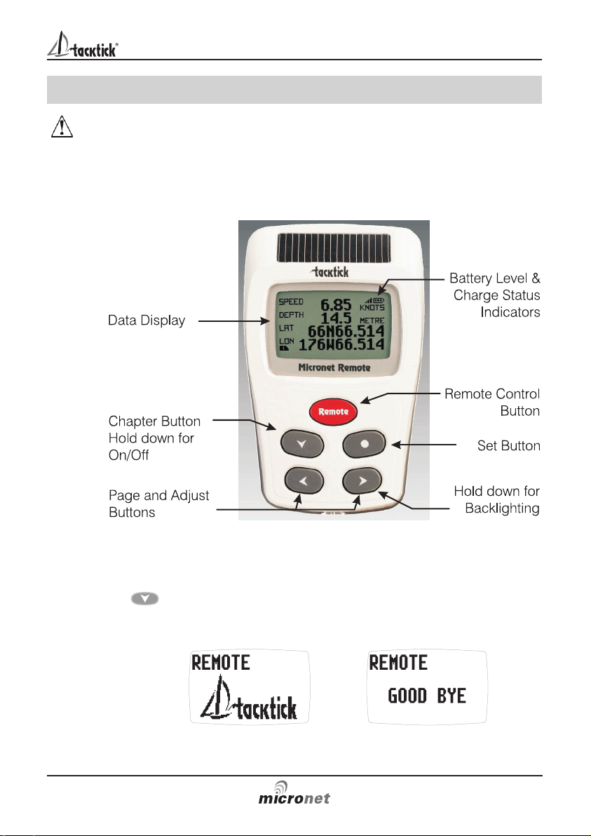
Remote Display
Page 2
Important
Due to the wireless communication systems used in Micronet
instruments they are only recommended for use on boats up to 18
metres (60 ft.) Before installing to a boat of aluminium or steel
construction, please contact your Tacktick dealer.
Like any other electronic instruments your Micronet system is designed
to serve only as an aid to navigation and it remains the skippers
responsibility to maintain a permanent watch and be aware of
developing situations.
Any attempt to take a Micronet product apart will invalidate the warranty.
The battery may only be replaced by a person trained and approved for
this purpose.
EMC Conformance
All Tacktick equipment is designed to the best industry standards for use
in the recreational marine environment. The design and manufacture of
Tacktick equipment conforms to the appropriate Electromagnetic
Compatibility (EMC) standards. Correct installation is required to ensure
that performance is not compromised.
Remote Display
www.tacktick.com
Page 3

Contents
1
www.tacktick.com
1 Information
Page
1.1 Introduction - 2
1.2 Specifications - 2
1.3 Power Management and Battery Life - 3
1.4 Safety and Disposal - 4
2 Operation
2.1 Display Information - 5
2.2 Switching the System On and Off - 5
2.3 Information Display Operation - 6
2.4 Remote Control Operation - 7
2.5 Backlighting - 8
2.6 Keylock - 9
2.7 Audible Signals and Alarms 9
2.8 Information Display - Data Item Descriptions - 10
3 Setup and Calibration
3.1 Entering Setup and Calibration Mode - 18
3.2 Setup and Calibration Chapter and Page Operation 18
3.3 Editing Values - 18
3.4 Setup Chapter and Page Organisation - 20
3.5 Setup Parameter Descriptions - 21
4 Seatrial and Calibration
4.1 Depth Offset - 31
4.2 Speed Calibration - 32
4.3 Wind Calibration - 33
4.4 Compass Calibration and Alignment - 34
5 Installation
5.1 Changing the Bezel - 35
5.2 Cradle - 35
6 Maintenance and Fault Finding
6.1 Care and Maintenance - 36
6.2 Fault Finding and Technical Support - 36
7 Warranty Information
Page 4

1 Information
1.1 Introduction
Your Tacktick Remote Display provides a unique combination of
features:
Mobile display of instrument data
All data available on your Micronet network can be viewed wherever you
are located on your vessel.
Remote control of Micronet displays
The Remote Display can control the other Micronet displays on your
network, i.e. Maxi, Dual Maxi and remote enabled models of the Digital,
Dual Digital and Analogue displays.
Solar Power
Your Micronet display is powered for life by the environment. Although
feature packed and highly visible in all conditions, current demand is so
low, and the supply so efficient, that the solar-powered display is self
sufficient. Combined with other displays in the Micronet range this
display becomes part of a complete navigational system.
1.2 Specifications
Height of digits: 15mm (0.6 inches)
Backlighting: 3 levels with daylight shutoff
System-wide or local control
Power: Solar Powered
300 hrs autonomy by day, 7 nights at brightest backlighting,
20 nights at economy backlighting without charge
Units of display: Boat Speed (knots, km per hour, statute miles per hour)
Distance (nautical miles, statute miles, kilometres)
Depth (metres, feet, fathoms)
Wind Speed (knots, metres per second, Beaufort)
Alarm: Audible Alarm for Depth, Wind, Cross Track Error and
Waypoint Arrival
Weight: 135g (0.3 lbs)
Operating Temp.: -10oto +60oC (14oto 140oF)
Frequency: 868 MHz or 916 MHz
Remote Display
2
www.tacktick.com
Page 5
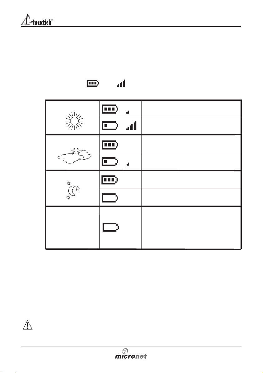
Bright Sunny Day
Overcast Day
Night
Battery is charged and being
topped up by the sun. (see Note)
Battery is low and being charged
by the sun.
Battery is charged and requires no
further charging.
Battery is low but maintaining it’s
level.
Battery is charged but is not
charging.
Battery is low with no charging.
It is recommended that the
instrument be left in daylight for
some time for the battery to
recover. A fully discharged battery
will recharge in approximately 12
hours of direct bright sunlight.
LOW Power
Information
3
If using the displays at night, power usage can be reduced dramatically
by switching the Backlighting to level 1 or Off. If Backlighting is not
required on displays located below decks it is best to set them to "Local"
backlighting control (see page 28 S38) so that power is not being
wasted in displays which may not be visible from the one being viewed.
Note: If the internal battery is fully charged then it does not matter how
much the display is subjected to bright sunlight no further charging is
required and the Charge Rate Indicator will remain low.
If the displays are to be stored for a long period of time before next use
(Over Winter) ensure that the batteries are fully charged before storage.
www.tacktick.com
1.3 Power Management and Battery Life
What makes your Micronet display possible is Tacktick’s revolutionary
approach to power management. By reducing the amount of power
being used by the electronics and maximizing the potential of the sun to
provide power, a Micronet display becomes a virtually perpetual device.
Power status is indicated by two icons on the display:
Battery Level and Charge Rate
Used together these icons will show the condition of the power supply.
Page 6
Pocket Mode
When Pocket Mode is enabled (see page 28 S35) the Remote display
switches off the LCD panel after a user configured time delay. The unit
remains connected to the network and pressing any button switches the
display panel back on.
Sleep Mode
If there is no boat speed or change in heading registered on the system
for a period of 12 hours your Remote Display will switch off to conserve
power. A "POWER SAVE" alarm will sound before the system switches
off. Pressing any button within 10 seconds of the alarm sounding will
allow the system to remain switched on.
Backlighting will automatically shut down/off when operated in daylight.
Artificial light WILL NOT recharge the battery. Placing your Micronet
display close to an artificial light will seriously damage the display. Only
recharge in natural daylight.
1.4 Safety and Disposal
Your Micronet display contains Manganese Lithium Dioxide batteries
which should be disposed of correctly. Do not dispose of any instrument
in domestic waste. Refer to regulations in force in your country.
If in doubt return the instrument to Tacktick Ltd. for correct disposal.
Remote Display
4
www.tacktick.com
Page 7
2 Operation
Important:
Ensure that the "Auto Network" procedure described on the yellow
instruction sheet and full Setup and Calibration has been performed
correctly before attempting to use your Micronet system.
2.1 Display Information
2.2 Switching the System On and Off
To switch your Micronet system on or off select any display and press
the button for 2 seconds.
Operation
5
www.tacktick.com
Switch on Switch off
Page 8

2.3 Information Display Operation
Information is displayed in a "Chapter and Page" format using the
button to scroll through the chapters and the and buttons to
move between the pages within a chapter. The diagram below shows
the information format.
Pressing the button at any time moves to the next Chapter and the
page last selected in that Chapter will be displayed. Both Chapter and
Page selection will scroll back to the first page once a cycle has been
completed.
Four chapters are available:
Single line displays
Eight pages, each displaying a single item of data. The data
item to be displayed on each page can be selected in setup
from the full list of data pages described in section 2.8.
See setup on page 25 S28.
Four line displays
Four pages, each displaying four data items. The data items
to be displayed on each page can be selected in setup from
the full list of data pages described in section 2.8.
See setup on page 26 S29
Rolling Road display
A single page displaying the following navigation data:
current waypoint name, distance to waypoint, course over
the ground (COG), speed over the ground (SOG), bearing to
waypoint, cross track error and turn angle.
A rolling road diagram illustrates the vessels course in
relation to the direct track from the previous to the current waypoint and
the direction to steer to return to the direct track.
Graph Displays
Two pages, each displaying a plot of a user selected data
item against time. See setup on page 26 S30.
For the wind direction graph, LFT and HDR labels indicate
the lift and header trend segments of the graph.
To alter the time span of a graph:
Press the button while the graph is displayed. The message
“CHANGE TIME” appears at the top of the page. Use the and
buttons to change the time span. Press again to confirm the
selection.
Remote Display
6
www.tacktick.com
Page 9

Operation
7
Default Chapter and Page diagram
2.4 Remote Control Operation
In this mode, the Remote Display is able to control the functions of other
displays on the Micronet network.
All remote control screens are displayed in "reverse", with white text on
a black background, to allow immediate recognition of remote control
mode.
Remote control mode is cancelled if a period of thirty seconds elapses
in which no key is pressed. The Remote Display automatically returns to
information display mode.
To enter Remote Control mode
Press and hold the button.
The Remote Display builds a list of the Micronet displays on
the network that are configured for remote control. This list
allows the user to select a display to control with the Remote
Display. The display that is currently selected for control is indicated by
the and markers around the display identifier.
The screen of the selected display will flash to indicate that it is under
remote control.
Displays on the network can be added to or removed from the list and
the order of the list can be modified. See setup on page 27 S32 for
details on how to configure the list
www.tacktick.com
Page 10

Remote Display
8
www.tacktick.com
To select a different display for control
Repeatedly press the button until the required display is
highlighted.
The screen of the newly selected display will flash to indicate that it is
under remote control.
To control the selected display.
Pressing the , , or button on the Remote Display
has the same effect as pressing that same button on the controlled
display. For example, pressing the button will cause the controlled
display to scroll to the next chapter.
The full range of operation and configuration functions on the controlled
display is available by pressing keys on the Remote Display.
Note: The first press of , , or on the remote display
causes the screen of the controlled display to stop flashing but the
controlled display remains under remote control until the Remote
Display exits remote control mode.
To exit Remote Control mode
Press and hold the button. The Remote Display returns to
information display mode.
If a period of thirty seconds elapses without a key press, remote control
mode is automatically cancelled and the Remote Display returns to
information display mode.
2.5 Backlighting
At any stage of the display’s operation press and hold for 2 seconds the
button to access the lighting control.
Pressing the and buttons will scroll through
setting OFF, 1, 2 and 3 whilst changing the backlighting.
Depending on the display setup (see page 28 S38),
Backlighting on the whole system or just the single display
will be altered.
In Pocket Mode, backlighting will turn off automatically after a preset
interval which can be configured in setup (see page 28 S35)
Backlighting is automatically switched off in daylight as part of the
display’s power saving feature and will not operate in daylight.
Page 11

Operation
9
www.tacktick.com
2.6 Keylock
The Keylock feature protects from accidental key presses.
You can enable or disable keylock as follows:
Press and hold to enter setup
Press repeatedly to reach the OPTIONS chapter
Press to open the OPTIONS chapter.
Press repeatedly to bring the KEY LOCK sentence to the cursor
Press to toggle between the ON/OFF options
Press and hold to exit setup.
Once keylock is activated, pressing a key causes the unit to
give the unlock key prompt. Press followed by to
unlock the keys (this will allow the keys to function for one minute, after
which the keys will automatically relock).
2.7 Audible Signals and Alarms
At stages during its operation your Micronet system will beep to indicate
alarms or moments of importance.
Power-up Once operating as part of a network the display will issue a single
beep as it is switched on by pressing the button for 2
seconds.
Button Press A single beep is issued each time a button is pressed. A second
beep is issued after a 2 second hold down of the button.
Timer A single beep will be issued at each minute of the countdown.
With 1 minute left to go a beep will sound every 10 seconds.
With 10 seconds to go a beep will sound every second.
Countdown complete will be indicated by a single burst of three
beeps.
Alarm Continuous bursts of three beeps will indicate an alarm.
The alarm activated will be indicated on the display. Pressing any
button will clear the alarm. See fault finding section on page 36.
Depth Shallow Alarm
The water depth has fallen below the preset alarm level.
The depth value that triggers the alarm is affected by any
keel or waterline offsets that have been added.
See page 21 S4 to set the alarm function.
This alarm does not sound as the depth increases above the preset
alarm level.
Page 12

Remote Display
10
www.tacktick.com
Depth Deep Alarm
The water depth has increased above or fallen below the
preset alarm level. The depth value that triggers the alarm is
affected by any keel or waterline offsets that have been
added. See page 21 s5 to set the alarm function.
Wind High Alarm
The wind speed has increased beyond the preset alarm
level. See page 22 S6 to set the alarm function.
This alarm does not sound as the wind speed decreases
below the preset alarm level.
Cross Track Error Large Alarm
A large cross track error has been alerted by the GPS.
See page 22 S7 to set the alarm function.
Waypoint Arrival Alarm
A waypoint arrival signal has been received from the GPS.
The waypoint name is shown on the top line of the display.
See page 22 S8 to set the alarm function.
2.8 Information Display - Data Item Descriptions
1 SPEED
The vessel's actual speed through the water as measured by
the Speed Transducer, displayed in the currently selected
speed units. See page 22 S9 to set units.
2 SPEED MAX (Maximum Speed)
The maximum speed encountered since switch-on or since
the last Maximum Speed Reset. To reset see page 21 S2.
3 SPEED AVG (Average Speed)
The average speed attained since switch-on or since the last
Average Speed Reset. To reset see page 21S3.
Page 13

Operation
11
www.tacktick.com
4 VMG WIND (Velocity made good to windward)
The vessel's calculated Speed Directly Upwind. This value is
calculated by the display from the Boat Speed and True
Wind Angle.
5 VMG WP (Velocity made good to waypoint)
The vessel's speed directly towards the active Waypoint. This
value is calculated by a GPS receiver or plotter.
6 LOG (Total distance travelled)
The total distance travelled by the vessel since installation of
the display or since a Factory Reset. See page 29 S40 to
reset.
7 TRIP (Trip distance travelled)
The distance travelled since the last Trip Reset. To Reset see
page 21 S1.
8 DEPTH
The actual depth beneath the vessel as measured by the
Depth Transducer.
Displayed in the currently selected depth units.
See page 22 S10 to select depth units.
The displayed value will be affected by any keel or waterline
offset added. See page 24 S18 to set an offset.
9 A WIND KNOTS/M S (Apparent wind Speed)
The apparent wind speed with respect to the vessel as
measured by the Wind Transmitter, displayed in the currently
selected wind units. See page 23 S11 to select wind units.
Page 14

Remote Display
12
www.tacktick.com
10 A WIND PORT/STBD (Apparent wind angle)
The apparent wind angle with respect to the vessel as
measured by the Wind Transmitter.
11 T WIND KNOTS/M S (True wind speed)
The true wind speed with respect to the vessel, calculated by
the display taking into account the vessels speed through
the water. Apparent Wind Speed, Angle and Boat Speed
must be available for this calculation.
12 T WIND PORT/STBD (True wind angle)
The true wind angle with respect to the vessel, calculated by
the display taking into account the vessels speed through
the water. Apparent Wind Speed, Angle and Boat Speed
must be available for this calculation.
13 WINDIR (True wind direction)
The true wind direction over the water, calculated by the
display taking into account the vessels speed through the
water and compass heading. Apparent Wind Speed, Angle
and Compass Heading must be available for this calculation.
14 BEAUF (Wind speed on Beaufort scale)
The actual wind speed over the water displayed using the
Beaufort scale, calculated by the display taking into account
the vessels speed through the water and compass heading.
Apparent Wind Speed, Angle and Compass Heading must
be available for this calculation.
15 SHIFT (Wind shift angle, head or lift)
Indicates changes in the wind against a compass heading.
Spotting these wind changes is the key to fast sailing
upwind.
The system automatically detects the mean wind direction
by averaging over a time period of 2 minutes to 60 minutes.
This time period can be changed in setup, see page 24 S22.
Page 15

Operation
13
www.tacktick.com
To manually overide this automatic calculation and set the mean wind
direction:
1. If a Wind Transmitter is included in your Micronet system then simply
press the button; (the current wind direction is stored as the
mean wind direction and displayed for 5 seconds during which time
the and buttons may be used to adjust the value.)
If the mean wind direction changes, press again.
2. If you do not have a Wind Transmitter included, sail close hauled and
press the button then tack and, once close hauled, press the
button again.
If the mean wind direction changes then the display may be updated
by pressing and holding the button while sailing on port tack,
the button while sailing on starboard tack or the button
while head to wind.
See Tacktick's "Using wind shifts to your advantage" sheet for further
information, this is available on the Tacktick web site, www.tacktick.com.
16 HEADING
Current magnetic compass heading of the vessel as
measured by the Compass Transducer.
The value displayed will be affected by the calibration routine
for the compass (see page 34).
The heading is displayed as degrees Magnetic or True
depending on the current compass setting.
See page 24 S24 to set.
17 TACKHDG (Heading on opposite tack)
Magnetic compass heading that the vessel will follow should
it tack through the wind, calculated by the display. Apparent
Wind Angle and Magnetic Heading must be available for this
calculation to be made.
18 SOG (Speed over the ground)
The vessel's speed over the ground as calculated by the
GPS Antenna or a GPS receiver.
Page 16

Remote Display
14
www.tacktick.com
19 COG (Course over the ground)
The vessel's course over the ground as calculated by the
GPS Antenna or a GPS receiver.
20 LAT (Latitude)
The vessel's current latitude as calculated by the GPS
Antenna or a GPS receiver.
21 LON (Longitude)
The vessel's current longitude as calculated by the GPS
Antenna or a GPS receiver.
22 BTW (Bearing to waypoint)
Bearing to (active) waypoint. The active waypoint being the
one to which the GPS is currently navigating as defined by a
GPS receiver or plotter.
The waypoint name will be displayed.
23 DTW (Distance to waypoint)
Distance to active Waypoint. The active waypoint being the
one to which the GPS is currently navigating as defined by a
GPS receiver or plotter.
The waypoint name will be displayed.
24 XTE (Cross track error)
The distance away from the direct track to the (active)
waypoint as defined by a GPS receiver or plotter.
The arrow indicates the direction to steer to get back onto
course to the waypoint.
Page 17

Operation
15
www.tacktick.com
25 TTG (Time to go to waypoint)
The calculated time remaining before you will arrive at the
(active) waypoint as calculated by a GPS receiver or plotter.
26 SEA (Sea temperature)
Current sea temperature as measured by the sensor in the
Speed Transducer.
Displayed in the current temperature units.
See p 23 S13 to select units.
27 RACE TIMER
Countdown and elapsed time clock.
The timer can only be set and operated in single item display
mode. In 4 line display mode the current state of the count
down or elapsed time can be viewed but not modified.
To set the countdown period:
Press and hold for 1 second the button.
Use the and buttons to set the required countdown time in
minutes.
Press the button quickly to prepare to start the countdown.
To operate the timer:
Press the button quickly to start the countdown.
The display will sound a single beep every 60 seconds until 1 minute
remains when a beep will sound at 10 second intervals. The final 10
seconds will count down with a beep each second with "START" being
indicated by a triple quick beep at 0 seconds.
At any time during the countdown a quick press of the button will
re-synchronise the timer to the nearest minute and commence
countdown from that point.
After the countdown is completed, the timer will automatically start to
count the elapsed time and this will continue until the button is
pressed and held for 2 seconds.
Page 18

Remote Display
16
www.tacktick.com
28 TIME
Current time as received from the GPS Antenna, corrected to
local time if an offset has been added.
See page 28 S37 to set an offset.
29 DATE
Current date as received by the GPS Antenna.
30 POWER
The voltage connected to the Power input of the Hull
Transmitter or the Wireless (NMEA) Interface.
Press to start
the countdown
Countdown in
progress
Press to reset
timer to the nearest
whole minute
Press and hold
to enter the timer
setup
Use and to
select the desired
countdown time
Press to store
the countdown time
Page 19

Setup and Calibration
17
www.tacktick.com
31 FFD-1 to FFD-6 (Custom data displays)
If you have a Wireless (NMEA) Interface connected to a PC with Tacktick
proprietary NMEA output capability (PTAK) then your six user defined
free format pages will be displayed in these custom data display pages.
Typically used by racing sailboats to show "Time to Layline" or corrected
True Wind Direction where the Upwash Correction Table is built into the
PC.
32 OFF (Null data item)
This item is used to mark a page of a single line display, or a line of a
four line display as "hidden".
Page 20

Remote Display
18
www.tacktick.com
3 Setup and Calibration
3.1 Entering Setup and Calibration Mode
To enter the Setup and Calibration menu press and hold for 2 seconds
the button.
Note: It is not possible to enter setup mode while the Race Timer is
currently visible on a single item display page. Scroll to a different page
in order to enter setup.
3.2 Setup and Calibration Chapter and Page operation
On entering setup mode a list of chapters is displayed, with the active
chapter marked with the cursor .
To change the active chapter:
Press the button repeatedly until the desired chapter title is
alongside the cursor.
To enter the active chapter:
Press the button. A list of pages is displayed with the active page
marked with the cursor .
Press the button to return to the list of chapters.
To change the active page:
Press the button repeatedly until the desired page title is alongside
the cursor.
To enter the active page:
Press the button. A list of parameters and current settings is
displayed with the active parameter over the cursor .
Press the button to return to the list of pages.
To change the active parameter:
Press the button repeatedly until the desired parameter title is over
the cursor .
3.3 Editing Parameter Values
Parameter values may be one of four types:
A user editable numeric value (for example, the shallow depth alarm
may have the value 3.2).
A resetable numeric memory value (for example the minimum depth
memory can be reset to the current depth).
A list of options (for example, the speed units parameter may have the
values KNOTS/KPH/MPH).
Page 21

Setup and Calibration
19
www.tacktick.com
An ON/OFF toggle (for example the Cross Track Error alarm can be
either ON or OFF).
To edit a numeric parameter value:
Press the button. The value data will begin to flash.
Use the and buttons to adjust the value.
Press the button again to set the new value.
To reset a memory value:
Press the button. The parameter is reset.
To select a parameter option from a list:
Press the button. The parameter option will begin to flash.
Use the and buttons to select the option required.
Press the button again to set the new option.
To toggle between ON/OFF parameter settings:
Press the button. The setting will toggle between ON and OFF.
Page 22

Remote Display
20
www.tacktick.com
3.4 Setup Chapter and Page Organisation
The diagram below shows the Setup and Configuration chapter and
page organisation.
For a full description of each setup parameter refer to items S1 to S47
on the following pages.
 Loading...