

Page 1
Volvo Penta IPS
Autopilot
System
DPU Installation
and System
Connections
Document Number : 8705 43
Date: July 2006
Page 2
2 Volvo Penta IPS Autopilot System
Handbook info rmation
T o the best of our knowledge , the information in this hand book was correct when
it went to press . However , Raymarin e cannot accept liabi lity for any inaccu racies
or omissions it m ay contain. In addition, our p olicy of continu ous product
improvement may change specification s without notice . As a result, Rayma rine
cannot accep t liability for any di fferences between the product and th e
handbook.
Autohelm, HSB (High Speed Bus), SailPil ot, SeaT alk and SportPilo t are registered
trademarks of Raymarin e
Raymarine , SmartPilot, AST (Advanced Steering Tec hnology), Au toAdapt,
AutoLearn , AutoRelease , AutoSeastate , AutoT ack, Au toT rim, F astT rim, GyroPlus ,
RayGyro , RayPilot and WindT rim are trademarks of Raym arine
Handboo k contents © Raymarine L td 2005 200 6.
Ltd.
Ltd.
Installation Procedures
1.1 Introduction
The V olvo P enta IPS Autopil ot System consists of an IPS S3G Co urse Computer
core pack and an I PS DPU .
The I PS S3G core pack con tains a Course Comp uter and a fluxgate com pass. T here
is no need to fit a drive unit or ru dder feedback unit . This sy stem can only be used
with a Volvo Penta IPS system.
The IP S Autopilot system is co mpatible with ST6001, ST7001 and ST8001 range of
autopilot co ntrol units . Raymarine wireless con trollers, th e S100 or
SmartControll er can be fitted as optional extras .
This ha ndbook will guid e you through th e installation of your IPS DPU and the
connection s that you will need to mak e to the other parts of the I PS system.
Page 3
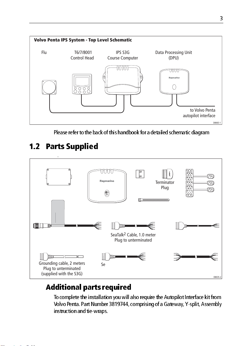
Volvo Penta IPS System - Top Level Schematic
3
Fluxgate
Compass
ST6/7/8001
Control Head
Please refer to the back of this han dbook for a detailed schem atic diagram
1.2 Part s Supplied
s
Data Processing Unit - Parts Supplied.
Junction Box
Data Processing Unit
(DPU)
CAUTION
DO NOT CONNECT
TO NMEA2000 BUS
IPS S3G
Course Computer
Ferrite
(x5)
Data Processing Unit
(DPU)
to Volvo Penta
autopilot interface
D8065-1
Terminator
Plug
5-way Junction Block
Tie Wraps
Raymarine VP interface cable
(Connector to unterminated.
Supplied with the S3G)
Grounding cable, 2 meters
Plug to unterminated
(supplied with the S3G)
2
SeaTalk
Cable, 1.0 meter
Plug to unterminated
2
Cable, 0.4 meter
SeaTalk
Plug to unterminated (x2)
SeaTalk Cable, 1 meter
to unterminated
NMEA 0183 Cable,
0.4 meter unterminated
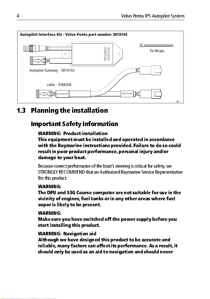
Additi onal p arts requ ired
T o complete the in stallation you will al so require the Autopil ot Interface kit from
Volvo Penta. Part Number 3819744, comprising of a Gateway, Ysplit, Assembly
instruction and tiewraps.
D8035-2
Page 4
4 Volvo Penta IPS Autopilot System
Autopilot Interface Kit - Volvo Penta part number 3819744
Tie Wraps
Autopilot Gateway - 3819743
Y-split cable - 3588206
MULTILINK
MULTILINK
D8036-1
1.3 Planning t he installat ion
Impo rtant Safe ty Inform ation
WARNING: P roduct in stallation
This equipment must be inst alled and operat ed in accordan ce
with the Raymarine in structions pr ovided. F ailure t o do so could
result in poor product performance , personal inj ury and/or
damage to your boat.
Because correct performan ce of the boat’ s steering is critical for safety , we
STRONGL Y RECOMMEND that an Au thorized Raymarin e Service Representative
fits this product .
WARNING:
The DPU an d S3G Course computer are not suitable for u se in the
vicinity of engines, fuel tanks or in any oth er area s where fu el
vapor is likely to be present .
WARNING:
Make sur e you have switched off the power supply before you
start in stalling this pr oduct.
WARNING: Navigat ion aid
Although we h ave designed th is product to be a ccurate and
reliable , many f actors can af fect its perform ance. As a result, it
should only be u sed as an aid to n avigation and shou ld never
Page 5
replace commonsense and n avigational judgeme nt. Always
maintain a permanen t watch so you can respond t o situations as
they deve lop.
EMC Inst allation Guidelin es
Please refer to the
guidelines
SmartPilot Comm issioning Guide
Prod uct dispos al
When you want to dispose of this produ ct (for example, at the end of its
working life), please do so in ac cordance with local reg ulations .
1.4S3G Cou rse Computer
Please refer to the SmartPilo t Commissioning Guide for detailed installati on
instruction s for the IPS S3G and fluxgate comp ass.
1.5 Contro l Head
Please refer to the Control H ead installation sheet for d etailed installation
instructions.
5
for applicable EMC
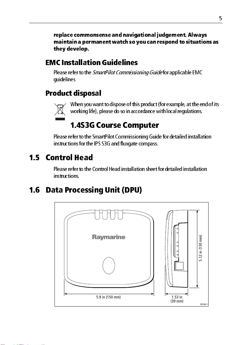
1.6 Data Pr ocessing U nit (DPU)
5.9 in (150 mm) 1.53 in
(39 mm)
5.12 in (130 mm)
D5536-1
Page 6

6 Volvo Penta IPS Autopilot System
CAUTION: The DPU is not waterpr oof and so must be installed in a
dry location.
The DP U must be positioned bel ow decks in a dry location where:
• It is protected agai nst physical dama ge.
• It is at least 9 in (230 m m) from a compass .
• It is at least 20 in (500 mm) from radio receiving equ ipment.
• There is reason able access for installation and servicing.
Fitting the Data Processing Unit
Fit the Dat a Processing Unit to a vertical surface , as follows:
1. Remove the outer cover .
2
1
D5794-1
2. Place the DPU in the requ ired position and mark the position of the fixing
holes.
3. Using a 1/ 8 in (3. 5 mm) drill, drill a p ilot hole for each of the t wo fixing screws .
4. Screw one of the selftappin g screws provided (No 8 x 1 in ) into each hole , so
each screwhead is at least 15 mm from the surface .
Page 7

D5776-1
5. Place the fixing holes o ver the screw heads, then m ove the DPU down so the
screw heads are at the top of the k eyhole slots .
6. Tigh ten the selftapping screws to secu re the DPU in position.
1.7 Running SeaT alk & NMEA2 000 cables
7
Cable r outing p ractic es
When runnin g cable, always observe the followin g guidelines:
• If a cable has to be fed thro ugh the deck, alway s use a good quality deck
gland.
• Where cables are fed throu gh holes, alw ays use grommets to prevent chafin g.
• Secure long cabl e runs so they do not presen t a hazard.
• Wherever possible , route cables aw ay from fluorescent ligh ts, engin es and
radio transmi tting equipment, as these may cause interference .
Identi fying cabl es
SeaT alk, SeaT alk2 and NMEA 20 00 buses are used in this system . SeaTalk uses a 3
core cable . SeaTalk
is availab le in both m adeup form with prefitted connectors , and in unterminated
form on a d rum.
2
and NMEA 2000 use a 5core , screened cable. Each cable type
Page 8

8 Volvo Penta IPS Autopilot System
SeaTalk connector
Bus co nnectors
If you are working with unterminated cable , use the details in the table below to
ascertain the correct co nnections . Cable boots are avai lable to cover the spade
terminals u sed to connec t unterm inated SeaTa lk
SeaTalk and NMEA2000 connections
SeaTalk SeaTalk2 and NMEA 2000
Wire Function Wire Function
Red 12 V + Shield Screen
Uninsulated 12 V Red 12 V +
Yellow Data Black 12 V
1.8 System power
CAUTION:
Incorr ectly connec ted power supplies could cau se damage to the
system
2
SeaTalk
connector
2
cables.
White Signal line high
Blue Signal line low
D5786-2
THE DPU IS POWERED VIA THE SEA TA LK CONNECTION. DO NO T CONNECT ANY
OTH ER POWER SOURCE TO THE DPU .
Page 9

Single power supply into SmartPilot computer
Single power supply
SmartPilot
computer
Computer
power supply
(via breaker/fuse)
SeaTalk bus
SeaTalk
9
SeaTalk instruments
DPU
SeaTalk
D9247-1
SeaTalk
SmartPilot
controller
Separate SmartPilot computer and instrument power
Another o ption is to p rovide separate power su pplies to the Smart Pilot compu ter
and SeaT alk system so you can ha ve independent, switch ed instrument and pilot.
Separate SmartPilot computer and instrument power supplies
SmartPilot
SeaTalk
computer
SmartPilot
controller
Computer
power supply
(via breaker/fuse)
SeaTalk bus
SeaTalk
SeaTalk instruments
SeaTalk
SeaTalk
Screen
Yellow
Do not connect Red wire
(Cut back and insulate)
DPU
Instrument SeaTalk
bus 12 V power supply
(via breaker/fuse
rated at 5 A or less)
D9246-1
Page 10

10 Volvo Penta IPS Autopilot System
1.9 Cable pr eparat ion
In an IPS system, cables not already fitted with molded connect ors must be
correctly prep ared for connection.
The DP U uses colorcoded, sp ring retention conn ectors. T o make a secure
connection to a spring retention connector , prepare the cable for connection, then
use the method illu strated below to connect each wire.
50 mm
9 mm
D5905-1
9 mm
1.10 Connecti ons to DPU
The dia gram below illustrates the co nnections that are requi red to and from the
DPU.
Ferrites
Ensure that all cab les connected to the DPU have a clip on ferrite fitted.
D5907-1
Page 11

RF ground
Yellow
grounding cable
SeaTalk2 Connector Block
12345
DO NOT CONNECT
TO NMEA2000 BUS
CAUTION
11
to Volvo Penta
Autopilot
Interface Unit
NMEA 2000
S3G Course
Computer Terminals
2
SeaTalk
SeaTalk
NMEA 0183
DPU
SeaTalk
Using the approp riate cable, connect the SeaT alk terminal on the DPU to one of
the SeaT alk terminals on the S3G Autopilot. You will need to cut off the mold ed
plug and stri p the cable as described abo ve.
Note:
Note that the term inals ar e color cod ed to match th e cable.
SeaTalk
Connect th e red and black wires of the SHORT SeaT alk2 cables to the red and black
terminals on th e DPU. Ensure the remaining wires are suita bly cut back and
insulated. P lug the other end into the SECOND terminal of a 5way SeaT alk
connector b lock.
2
D8037-2
2
NMEA 0183
Connect the NMEA 0 183 terminal on the DPU to th e NMEA 1 terminal on the S3G
course comp uter . Ensure that th e following connectivity is achieved:
Page 12

12 Volvo Penta IPS Autopilot System
Wire Color DPU Connection S3G Connection
Red NMEA 0183 In + NMEA 1 Out +
Blue NMEA 0183 In NMEA 1 Out
Yellow NMEA 0183 Out + NMEA 1In +
Green NMEA 0183 Out NMEA 1 In
NMEA 2000
Using one of the SHORT SeaT alk2 cables , connec t the NMEA 2 000 termin al on the
DPU to the FOURTH term inal of the 5way SeaT alk
2
connector blo ck.
Securing cables and replacing cover
When all of the DPU cab les have all been connected, secu re each cable to the
loops on the D PU, u sing the cable ties provided .
When all cables are secur e, replace the D PU cover .
Do not use the DP U with the cover removed, as this could degrade the EMC
performance.
1.11 Additi onal connections
Three mo re connections now need to be made to the 5way connector block.
SeaTalk2 terminator
Plug t he SeaTalk2 terminator into the CENTER termi nal on the 5way SeaT al k2
connector bl ock.
Grounding the system
In order to meet the system EMC specification, th e SeaT alk2 cable screen m ust be
connected to th e vessel’s RF ground po int.
Using the grounding cable
Raymarine provide a madeu p, RF grounding cab le that you are recommended to
use, to ground the system.
The gro unding cable is y ellow and has a SeaT alk2 connector at one end . Connect
this to the FIRST terminal of the 5w ay SeaT alk
2
connector blo ck. The
Page 13

unterminated end of the cable is stripped, for co nnection to the vessel’s RF ground
point.
If you require ad ditional advice on g rounding the IP S DPU, please contact the
Raymarine T echn ical Support Depart ment.
1.12 Connecting t o the V olvo Penta sys tem
Vol vo Penta G ateway
CAUTION:
Consult your Volvo Pe nta dealer bef ore making a ny changes t o
your existing system.
Note:
To connect to the Volvo Pen ta system you will need to obtain an Auto pilot Interface
kit from Volvo Penta. P art Num ber 38 19744 , compr ising o f a Gat eway, Ysplit , Ass embly
instructio n and two tiewraps.
Plug the LONG SeaT alk2 cable into the FIFTH termina l of the 5way SeaT alk
connector b lock.
Thread the cable into the junct ion box and connec t to the connector bloc k.
Then , thread the bare end of the Rayma rine VP interface cable into th e junction
box and conn ect to the connector blo ck. Ensure that the wire colors m atch.
13
2
CAUTION:
Do NOT connect the Rayma rine VP in terface cable to NMEA2000,
or the sy stem could malfu nction.
Connect the other end of the Raym arine VP interface cable (circular connector) to
the connector on the Volvo P enta Gateway.
1
2
DO NOT CONNECT
TO NMEA2000 BUS
CAUTION
D7940-2
Page 14

14 Volvo Penta IPS Autopilot System
Y split cable
Connect the Ysplit ca ble to the Volvo P enta Gateway. Use the connection tha t
DOES NOT ha ve a yellow “MUTILINK” label.
3
MULTILINK
Finall y, connect to the V olvo Penta sy stem bus using the “MUL TILI NK” ends of the
Ysplit cable .
4
MULTILINK
5
MULTILINK
1.13 EMC Confor mance
Always ch eck the installation before go ing to sea to mak e sure that it is not
affected by radio tran smissions , engine starting etc.
MULTILINK
D7941-1
MULTILINK
MULTILINK
D7942-2
1.14 Post installat ion Checks
Before you proceed to the commissioning stage, it is imp ortant to verify your
installation . Please follow these simple proc edures before commission ing:
Page 15

15
1. Po wer up the IPS autopilo t system and start the V olvo Penta IPS engines
Move the helm by hand and observe the ships rudd er gauge and the rudder
bar on the cont rol unit. T hese displays should be synchronized .
If they are not:
i. Check that the Volvo Penta aut opilot interface is connected correctly . Y ou
will need to consul t your Vo lvo Penta service agent.
ii. Check that the connections in the jun ction box match co lor for color , at
the connector b lock.
iii. Check the NMEA OUT connectio ns at the DPU and that they ar e seated
properly in the connector .
iv . Check the NMEA IN conn ections at the S3G and that they are seated
properly in the connector .
2. Drive the boat at a slow speed (ap proximately 5 knots) and press
the control un it. Y our boat shou ld continue on it s current heading.
AUTO
on
If the control un it reads “NO IPS” then repeat the wiring checks in step 1.
3. Use either the +10 or 10 keys or the rotary control to mak e a course change .
Y our boat should alter course as directed.
If the autopilo t does not respond, th en repeat the wiring checks in step 1 .
4. The au topilot is now ready for the commissioni ng process . Please refer to the
commission ing sec tion o f the SmartPilot Commissi oning Guide .
Page 16

16 Volvo Penta IPS Autopilot System
Autopilot
Interface Unit
to Volvo Penta
D8055-3
System Connections
(Single power supply)
CAUTION
DO NOT CONNECT
TO NMEA2000 BUS
Volvo Penta IPS Autopilot
Connector Block
2
12345
SeaTalk
Junction Box
Yellow grounding cable
RF ground
IPS Data Processing Unit
Computer
power supply
(via breaker/fuse)
ST6001
Control Head
GPS
RS125
S3G Course Computer
Compass
 Loading...