

Page 1

Distributed by
Any reference to Raytheon or
RTN in this manual should be
interpreted as Raymarine.
The names Raytheon and RTN
are owned by the
Raytheon Company.
Page 2
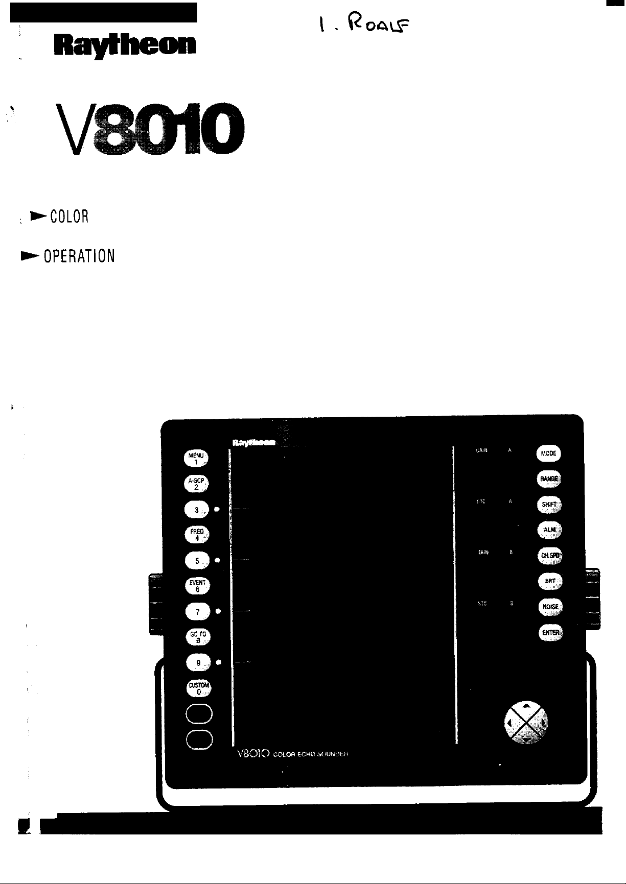
: WCOLOR
ECHO SOUNDER
+OPERATlON
MANUAL
Page 3

COLOR ECHOSOUNDER
OPERATION MANUAL
PURPOSE
This manual contains very important information on the installation,
operation, and maintenance of your new equipment. In order td get the best
results in operation and performance, please take the time to read this
manual thoroughly.
**-**
This
device is only an aid to
jlktors
improper handling or use. It is the
prudence andnavi@ionaljudgment, and thisdevice shouldnot be relied upon
as a
including
substUejb,r
IMPORTANT NOTICE
navigation.
equipmentfre
such prudence and judgment.
Its accumcy can be
ordeficts, environmental conditions, and
user’s nzsponsibility
*******
a&ted
to
e.wcise
FIRST EDITION
April, 1993
by
common
many
Page 4

RAYTHEON MARINE COMPANY products are supported by a network of Authorized Service Representatives. For information on Raytheon
products and services, contact any of the following regional offices:
UNITED
STATES . . . . . . . . . . . .
Raytheon Marine Company
46 River Road
Hudson NH. 03051
Telephone: (603) 881-5200
Raytheon Marine Company
1521 So. 92nd Place
Seattle, Wa. 98108
Telephone: (206) 763-7500
EUROPE . . . . . . . . . . . . . . . . . . .
Raytheon Marine Sales & Service
Elizabeth Way,
The Pinnacles,
Harlow,
Essex CM19 5AZ.
United Kingdom.
Telephone:
44-
(0) 279 444 244
Page 5
Table of Contents
INTRODUCTION
1 .lGENERAL
1 .2ABOUT THIS MANUAL..
1.3
ECHO
1 .4GPS GENERAL
INFORMATION..
SOUNDING
INFORMATION..
GENERAL
INSTALLATION
2.1 GENERAL . . . . . . . .
2.2
UNPACKING AND INSPECTION
2.2.1
2.2.2
2.3
INSTALLING THE
2.3.1
2.3.2
2.4
CONNECTIONS..
2.4.1
2.4.2 Data Input/Outputs..
2.4.3
2.4.4
2.4.5
2.4.6
Equipment Supplied..
Accessories&Options..
Standard
Console
Power Input
GPS
Sensor(Option).
SeaTalk
Video
Grounding The Echosounder..
Interface
Output..
.._.......................................................................
DISPLAY
Mounting
Mounting
......................................................................
...................................................................
...............................................................
.........................................................
............................................................
INFORMATION
..................................................
...................................................
........................................................
...................................................
UNIT
.........................................................
..........................................................
........................................................
.......................................................
............................................................
...............................................
...........................................
................................ .3
.l
.2
.5
9
.9
10
1 1
1
1
.l 1
14
14
15
.17
19
.19
19
9
2.5
TRANSDUCER INSTALLATION
2.5.1
2.5.2
2.5.3 252BL Lexan Transducer Installation
2.5.4 252BB Bronze Thru-Hull Transducer..
General
General
Mounting
2.5.3.1
2.5.3.2
2.5.3.3 Preparation 3- The Location
2.5.3.4 Transducer
2.5.3.5 Inside Hull Installations
2.5.3.6 Steel Hull Installations
2.5.4.1 Locating the 252BB .............................................
Information..
Mounting Considerations..
Location-
Preparation
Preparation2- The
.................................................
......................................................
Displacement
1- The
Installation
Stuffing Tube..
Fairing
...................................
Hulls
......................................
.......................................
.........................................
............................
................................. 24
........................
Block..
.........................
...............................
...............................
.20
.20
.21
.22
.24
.24
.25
..2 6
.30
.30
.34
.34
Page 6
2.5.5
2.5.4.2 Preparing the Installation
Installing
SpeedfTemperature
the
OPERATION
....................................
Unit..
...........................
.35
.38
3.1 GETTING STARTED
3.1 .lThe Keyboard
3.2 THE BASIC CONTROLS
3.2.1 The Power Control Keys
3.2.2
3.3 DISPLAY MODES..
3.3.1 STD
3.3.2
3.3.3
3.3.4 STDlBTM Display..
3.3.5 CRUISE DISPLAY..
3.3.6 PLOT/TEMP Mode..
3.3.7 NAVIGATION
Brilliance
3.2.2.1
FishFinder
3.3.1 .l Fishfinder/A-Scope
3.3.1.2 Frequency.. ..........................................
3.3.1 .3
3.3.1 .4 Using the
3.3.1.5 Selecting Range Scales
3.3.1 .6 Setting
3.3.1.7 Setting the Gain
3.3.1.8 Setting the STC
3.3.1.9 Controlling the Chart Speed
3.3.1.10 Setting and Using Alarms
3.3.1 .l 1 Noise Suppression/Interference Reduction
STDISTD
STD/ZOOM
3.3.5.1 CRUISE Operations.
3.3.5.2 NAV Alarms - The Set Alarm Menu .....................
3.3.6.1 Operations for Plot.Mode
3.3.6.2 Selecting
3.3.6.3 Navigating to Waypoints
3.3.6.4 Using EVENT Marks
3.3.6.5 Re-centering Own Ship
3.3.6.6 The TEMP
3.3.7.1 Navigation
.................................................................
...............................................................
Control..
Backlighting
..................................................................
Mode
Saving
Mode
Mode
Display
3.3.7.1.1
3.3.7.1.2
3.3.7.1
...........................................................
.............................................
..........................................................
the
Keypad..
.....................................................
..............................................
Events..
Shift..
..............................................................
Plot Scales
.3
..................................................
VRM
..................................................
....................................................
...............................................
................................................
...........................................................
..........................................................
.........................................................
............................................
........................................................
Graph
Operations..
GOT0 a Selected Waypoint: ...............
Store
Route
...............................................
.....................................................
an
Following Operations ................
....................................
..........
.._
.......................................
.................................
..................................
...........
....................................
..........................................
.....................................
...........................................
.........
......................................
EVENT..
..............................
....
.41
.42
.44
.44
.45
.45
.45
.46
47
48
.48
.49
.49
.50
.52
.53
.53
.54
.57
58
.59
.60
.60
.61
.62
.67
.68
.68
.68
.69
69
.70
.72
.73
.73
.73
.73
Page 7
3.3.8
3.4
MENU
3.4.1
3.4.2
3.4.3 NAVIGATION Menu
3.4.4
The CUSTOM
Key
Operations . . . . . . . . . . . . . . . . . . . . . . . . . . . . . . . . . . . . . . . . . . . . . . . . . . . . . . . . . . . . . . 74
FISHFINDING
3.4.1.1
3.4.1.2 Auto Gain
3.4.1.3
3.4.1 .4 Screen Colors
PLOTFEMP
3.4.2.1
3.4.2.2 PLOT DISPLAY
3.4.2.3
3.4.2.4 TRIP LOG Reset .
3.4.3.1 NAVIGATE SETUP Menu .
3.4.3.2
ROUTE
3.4.4.1
White
Simulator Mode
TRACK CONTROL
RTE
3.4.3.1 .lMagnetic
3.4.3.1 .2Display Type . . . . . . . . . . . . . . . . . . . . . . . . . . . . . . . . . . . . . . . . 82
3.4.3.1
STORE
3.4.3.2.1
3.4.3.2.2
3.4.3.2.3
3.4.3.2.4 SAVE Operations - WAYPOINT LIST . . . . . . . 89
PLANS . . . . . . . . . . . . . . . . . . . . . . . . . . . . . . . . . . . . . . . . . . . . . . . . . . . . . . . . . . . . . . . . 90
ROUTE
3.4.4.1 .l
3.4.4.1.2
3.4.4.1 .3Listing
3.4.4.1 .4Editing
Key . . . . . . . . . . . . . . . . . . . . . . . . . . . . . . . . . . . . . . . . . . . . . . . . . . . . . . . . . . 74
Menu . . . . . . . . . . . . . . . . . . . . . . . . . . . . . . . . . . . . . . . . . . . . . . . . . . . . . . . . . 75
Line
Menu . . . . . . . . . . . . . . . . . . . . . . . . . . . . . . . . . . . . . . . . . . . . . . . . . . . . . . . . . . . 77
INPUT
WAYPOINTS
. . . . . . . . . . . . . . . . . . . . . . . . . . . . . . . . . . . . . . . . . . . . . . . . . . . . . . 75
. . . . . . . . . . . . . . . . . . . . . . . . . . . . . . . . . . . . . . . . . . . . . . . . . . . . . . . . .
. . . . . . . . . . . . . . . . . . . . . . . . . . . . . . . . . . . . . . . . . . . . . . . . 76
._.........._.......................................
Menu . . . . . . . . . . . . . . . . . . . . . . . . . . . . . . . . . . . . . . . 77
Menu . . . . . . . .
. . . . . . . . . . . . . . . . . . . . . . . . . . . . . . . . . . . . . . . . . . . . . . . . . . . . . . . . 79
.._....._........................................
._.......................................................
Correction
.3 Loran-C
Naming
Store
WAYPOINT
Menu . . . . . . . . . . . . . . . . . . . . . . . . . . . . . . . . . . . . . . . . . . . . . . . . . . . . 91
Selecting
Making Route
Chain . . . . . . . . . . . . . . . . . . . . . . . . . . . . . . . . . . . . . . 82
Menu . . . . . . . . . . . . . . . . . . . . . . . . . . . . . . . . . . . 82
Waypoints
Waypoint
. . . . . . . . . . . . . . . . . . . . . . . . . . . . . . . . . . . . 84
LIST Operations . . . . . . . . . . . . . . . . . . 88
Routes . . . . . . . . . . . . . . . . . . . . . . . . . . . . . . . . . 91
Routes . . . . . . . . . . . . . . . . . . . . . . . . . . . . . . . . . . . . . 95
Routes . . . . . . . . . . . . . . . . . . . . . . . . . . . . . . . . . . . . . 96
.._...............................
.._.................................
. . . . . . . . . . . . . . . . . . . . . . . . . . . . . 81
. . . . . . . . . . . . . . . . . . . . . . . . . . . . . . . 84
Plans . . . . . . . . . . . . . . . . . . . . . . . . . . . . . 93
75
76
79
79
80
81
3.5
GPS
3.5.1
3.5.2
MODE
Getting Started
3.5.1 .lEstimated
3.5.1.2Antenna
3.5.1
The SATELLITE STATUS Page . . . . . . . .
3.5.2.1
. . . . . . . . . . . . . . . . . . . . . . . . . . . . . . . . . . . . . . . . . . . . . . . . . . . . . . . . . . . . . . . . . . . . . . . . . . . . 96
with GPS . . . . . . . . . . . . . . . . . . . . . . . . . . . . . . . . . . . . . . . . . . . . . . . . . 97
Position . . . . . . . . . . . . . . . . . . . . . . . . . . . . . . . . . . . . . . . . . . . . . . . 97
Height . . . . . . . . . . . . . . . . . . . . . . . . . . . . . . . . . . . . . . . . . . . . . . . . . . . 99
.3 Entering
SATELLITE -SF
3.5.2.1.1
3.5.2.1.2 Search The Sky
3.5.2.1.3
3.5.2.1.4
3.5.2.1.5
3.5.2.1.6 4 L/L
3.5.2.1.7 Response
Date& Time
FixType
HDOP
POSITION
Geodetic System
. . . . . . . . . . . . . . . . . . . . . . . . . . . . . . . . . . . . . . . . . . 99
Menu . . . . . . . . . . . . . . . . . . . . . . . . . . . . . . . . . . . . . . . 102
. . . . . . . . . . . . . . . . . . . . . . . . . . . . . . . . . . . . . . . . . . . 102
Level . . . . . . . . . . . . . . . . . . . . . . . . . . . . . . . . . . . . . . 103
CORR.
. . . . . . . . . . . . . . . . . . . . . . . . . . . . . . . . . . . . . . . . . 104
=L/L
.._._.._.._.......................
. . . . . . . . . . . . . . . . . . . . . . . . . . . . . . .
. . . . . . . . . . . . . . . . . . . . . . . . . . . . . 103
. . . . . . . . . . . . . . . . . . . . . . . . . . . . . . 104
=SPD . . . . . . . . . . . . . . . . . . . . . . . 105
99
102
Page 8

3.6 SYSTEM SETUPS.. ................................................................. 106
3.6.1 INPUT/OUTPUT ........................................................... 106
3.6.1.1 NavIn............................................................ 106
3.6.1.2 Data Out.. ....................................................... 106
3.6.1.3 Heading In.. ..................................................... 107
3.6.1 .4
3.6.2 UNITS ........................................................................ 107
3.6.2.1 Selecting
3.6.2.2 Changing Temperature Units.. ............................ 108
3.6.2.3 Changing Units of Speed..
3.6.2.4 Changing
3.6.3 CALIBRATE Menu.. ...................................................... 109
3.6.3.1 Calibrate Temperature.. ...................................... 109
3.6.3.2 Calibrate Speed.. .............................................. 109
3.6.3.3 Calibrate TX Frequency..
3.6.4 Master
SpeedIn......................................................... 107
UnitsofDepth ................................... 108
.;.
108
109
1 10
1 1 1
Reset
..............................
Language
...............................................................
..........................................
....................................
MAINTENANCE
4.1 GENERAL
4.1 .lPaddle Wheel Maintenance..
4.1 .2 Transducer Maintenance ................................................
4.2 ELECTRICAL..
4.2.1
4.2.2 Replacing the Batten/
4.2.3 Self Test Mode
4.2.4 Auto Temperature Calibrate Mode..
4.2.5
4.3
TROUBLE
4.4 SPARE PARTS
4.5
SPECIFICATIONS . . . . . . . . . . . . . . . . . . . . . . . . . . . . . . . . . . . . . . . . . . . . . . . . . . . . . . . . . . . . . . . . . . . . . . . . .
..............................................................................
...........................................
........................................................................
Replacing
Service
4.2.3.1 Dis-assembly For Service....................................
4.2.3.2 Power
4.2.3.3
4.2.3.4 TX/Rx Adjustments ........................................... TBA
SHOOTING
the
Fuse
........................................................
.....................................................
.............................................................
.................................
Alignments.. ......................................................
Supply
Color
.............................................................................
Monitor Adjustments..
CHART .......................................................
Adjustments.................................
............................... TBA
113
1 13
1 14
1
14
1 14
115
1 15
1 16
TBA
TBA
TBA
Page 9
SECTION I
INTRODUCTION
1.1 GENERAL INFORMATION
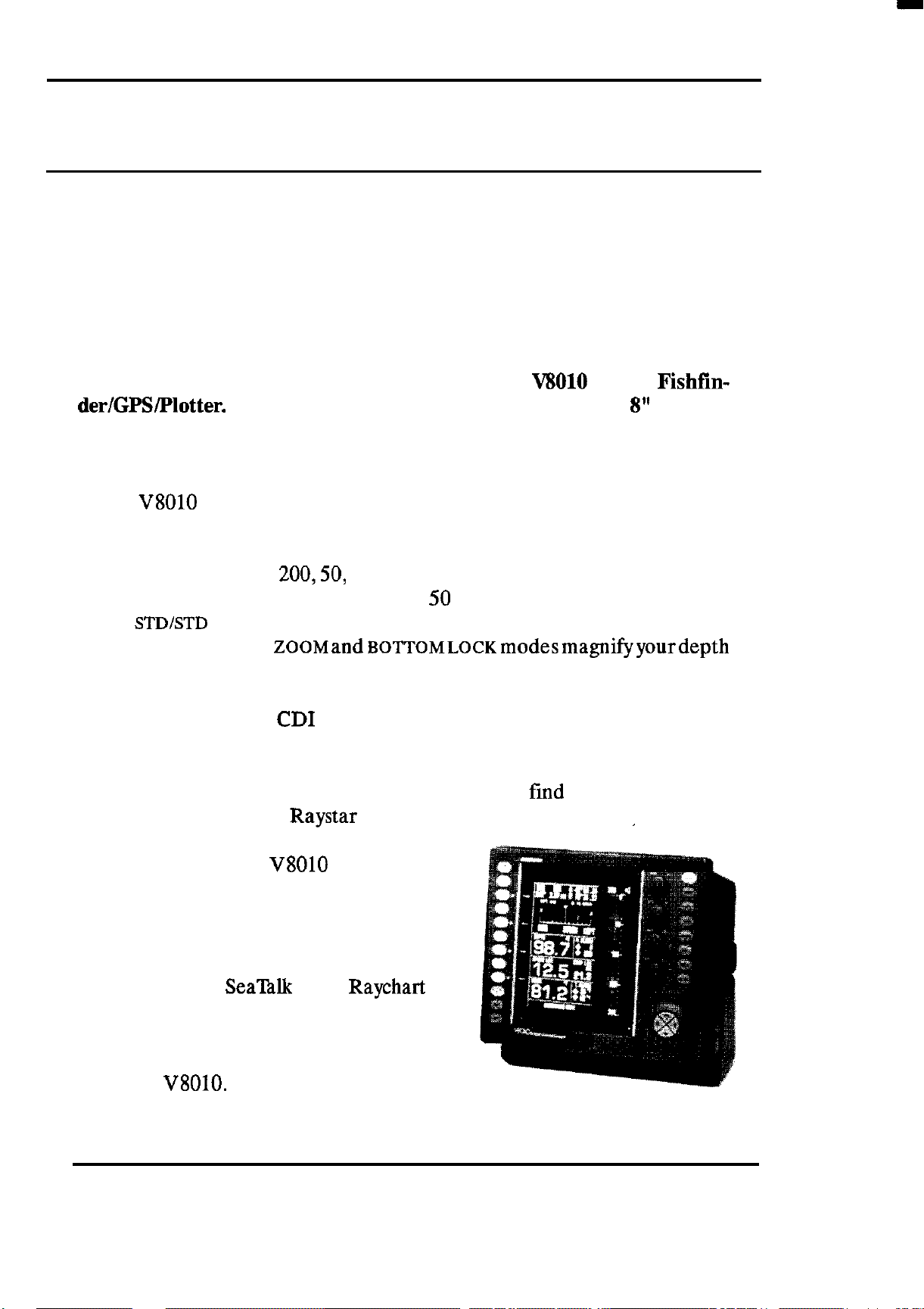
Congratulations on the purchase of your new
der/GPS/Plotter.
which combines the most useful fishing display modes in 8 or 16 bright
colors together with GPS or other external Navaid data.
The V8010 provides simple and direct access to your navigation and
fishfindingdata using simple on-screen menus and one -button operations.
The Fishfinding modes include STANDARD displays of fish and the bottom
profile using either the 200,50, or 28Khz 1000 watt transmitters. There’s a
split-screen display of both the 200, and 50 (or 28) Khz frequencies together
called
trackingtogether.The
presentations for a better look at the fish in mid-water or on the sea bottom.
Plot tracker records your vessel’s track to destinations so you can trace the
path back home again. The Plot Tracer cursor helps spot the surface
temperature break points on the plotter so you can
and the fish. When the Raystar 100 GPS sensor is connected. automatic
satellite acquisition and tracking lets the
GPS mode turn the
navigation system
STDISTD
Graphic plotting and
We think you’ll appreciate the unit’s large 8” display
mode which provides best views of fish detection and bottm
ZOOMand~~TT~~~~~~modesmagnifyyourdepth
CD1
displays steer you to waypoints efficiently. The
V8010
into a full
Vii010
find
Color Fishfin-
the warm currents
Although we could go on describing
the exciting new features such as Multi-
color
Electronic Charting option, we’re sure
that you will enjoy will discovering and
using the many new features found in
your new
A-SCOPE,
V8010.
SeaTalk or the
Raychart
INTRODUCTION 1
Page 10
1.2 ABOUT THIS MANUAL
This manual contains important information to help you get the best
operation and performance from your new
V8010.
Although the unit is
pretty simple to master, please take the necessary time to read through the
each section.
In the event that you are using a GPS or a fishtinder for the first time, this
Introduction contains a brief discussion on the general principles of
finding and, if you’ve added the
V8010
system, a brief description of how the GPS satellite system works is
Raystar
100 GPS sensor option to your
included.
Section 2 contains very important information on the proper installation
of your new
V8010
Color Fishlinder/Plotter/Navigator. Although the typical installation might seem straight forward and simple, we highly recommend that this section be read
thoroughly
and the guidelines for installation
be closely followed to obtain trouble-free and efficient operation of your
new unit.
fish-
Section 3 contains the operating instructions for the
V8010
Color
Echosounder and will guide you through the unit’s operating controls and
display layouts. To more easily recognize how to enable the various operations, the names of keys that must be pressed to corn lete the described
operation are enclosed in boxes, such as
I-,
or
RANGE
rf
. In most cases,
pictures, showing the correct displays for the desired entry, are included
next to each function.
Some of the functions appear on the screen in temporary menus or boxes
whenever the blue keys such as
m
or
ml
are pressed. Numeric
values appearing in the boxes can be changed by pressing the UP or DOWN
direction keys. Other menu functions are enabled when the corresponding
‘softkey” is pressed.
The best way to learn about your
V8010
is to dive right in. You can’t
damage the unit by randomly pressing keys. So don’t be afraid to experiment. If at any time the results appear confusing, just push
themkey
and start again.
Section 4 contains some technical information on the Basic Care and
Maintenance for your unit. In the event that your
V8010
should ever
INTRODUCTION 2
Page 11
experience an operational failure, it is recommended that all repair services
be provided by an authorized Raytheon service dealer or by the Raytheon
Factory Service Center.
Before proceeding, please take a few moments to fill out the Warranty
Registration Card located behind the front cover of this manual. Then
return the card to Raytheon Marine Company. No postage is required
card is mailed in the U.S.A.. This card must be returned to assure the
registration of the warranty for your unit.
1.3
ECHO SOUNDING GENERAL INFORMATION
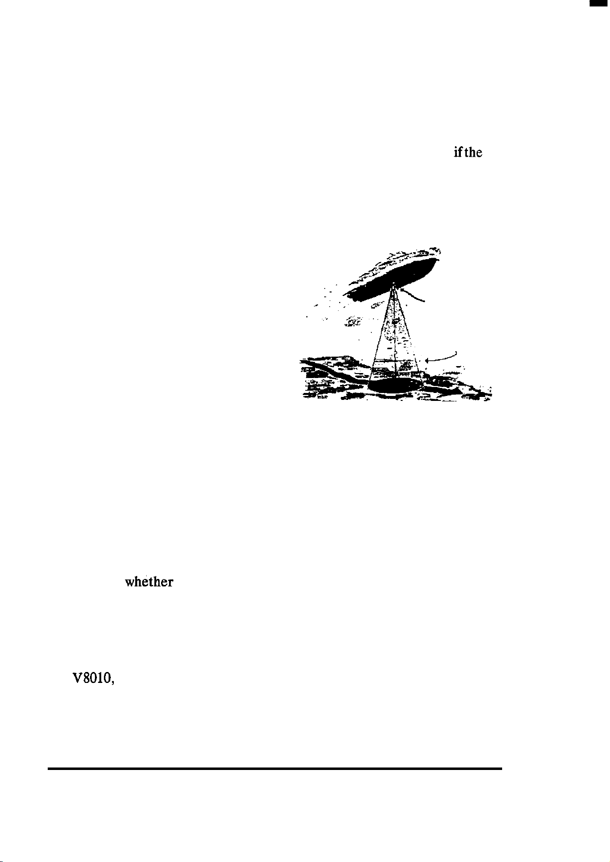
An echo sounder is a device which transmits an ultrasonic energy wave into the
water; listens for echoes from that ultra-
-:
TRANSDUCER
sonic wave and then displays the returning
echoes onto the LCD panel or CRT video
display. The elapsed time that it takes for
ENERGY WAVE
the pulse energy to travel down through
the water and be reflected back as echoes
can be measured and converted into units
of depth in the echo sounder.
ifthe
The frequency of this “ultrasonic” wave, the beam angle at which it is
transmitted, and the power at which it is sent will all
play
an important part
in determining the appearance of the echoes on the display.
The normal components of an echo sounder are a display unit containing
the electronic circuits, and a transducer for sending and receiving the sonic
energy. The echo sounder is one of the most useful pieces of electronic
equipment aboard a boat. In addition to indicating the depth of the water,
it can indicate whether the bottom is hard or soft, smooth or irregular in
contour and
whether
fish are present below the boat.
Echo returns from the bottom, from fish or fish schools, seaweed, grass,
bubbles, or plankton are received by the echo sounder in various echo
strengths. The bottom echo is usually the strongest echo return while
returns from fish are generally very weak. In color echo sounders, such as
the
V8010,
these different echoes are displayed in distinct colors (up to 16
colors can be used) for easy recognition by the operator. Whether fish
INTRODUCTION 3
Page 12
echoes are displayed on the echo sounder (or not) can depend on several
factors including:
*The type or species of the fish
l
Number and sires of the fish
l
Depth of fish below the boat
l
Gain control setting
*Transmitter Power and frequency
l
Transducer beam angle
l
Speed of the boat
l
Turbulence in the water
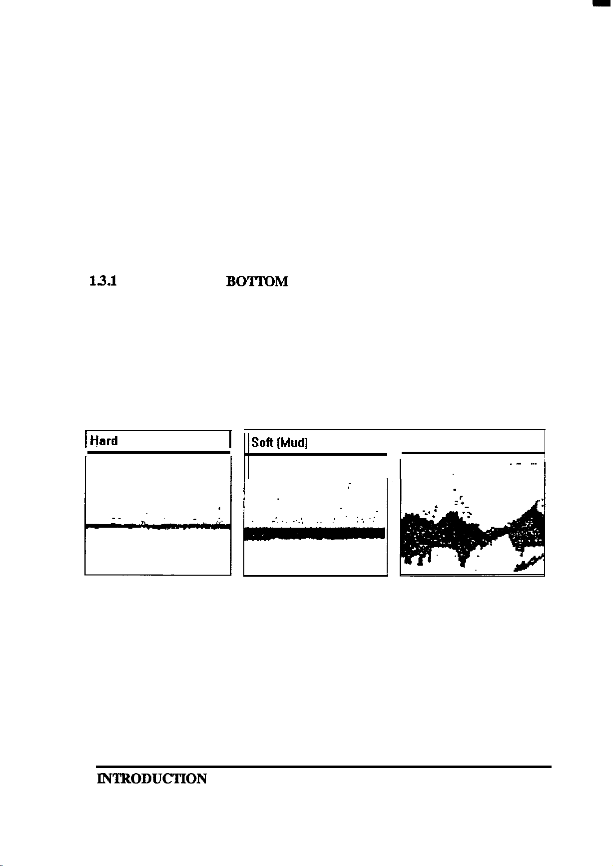
1.3.l
DETERMINING
To understand how bottom conditions affect the bottom echo’s appearance on the display, consider the signal transmitted from the transducer as
a cone-shaped beam of approximately 10 degrees. If the sea bottom were
as hard and flat as a mirror, only the signal directly under the transducer
would be reflected back to the transducer, and there would be a narrow
bottom echo line printed on the display screen.
BOTTOM
CONDITIONS
1 Hard
Bottom (Sand]
.
1
1
Soft(Mud] Bottom
/
_,
Rock
[Live]
Bottom
H
This type of echo line is typical characteristic of hard sandy sea bottoms.
Sometimes when the depth is shallow and the bottom is
echo can appear at exactly double the depth of the true bottom echo.
If the sea bottom is softer (sea grasses or muddy), the echo bottom line
would print thicker on the screen. This is because the echo consists not only
of that weaker echo reflected from the top surface of the grass or mud, but
very hard
,a second
IN’I’BODUCTION
4
Page 13
includes some energy that penetrates into the grass
, soft
sand, or mud and
then reflects back to the transducer slightly delayed in time. Under some
conditions, the sonic energy is strong enough to penetrate the soft bottom
and show a harder sub-botton such as an oyster beds or ledges.
If the sea bottom is made up of coral beds, wrecks, or rock piles, the
irregular surfaces of the bottom structures provide a series of closely spaced
echo returns from the various angles of the bottom. On screen, the bottom
line appears irregular with long tails as shown in the “Live Bottom”
figure.
Generally, these bottom conditions provide an ideal habitat for locating
fish.
On your display the echoes are printed on the CRT screen beginning at
the right edge adjacent to the range scale marks. Each time the echo
sounder transmits and receives, the new echoes replace the old echoes at
the right edge and the picture is
shifted
to the left. You can see the received
echoes even more clearly when you turn on the A-Scope feature of the
V8010.
that you have passed over
Eventually a historical
lYll
picture of the bottom contour
the screen.
and
fish echoes
The
V8010
SOKhz,
quency
operates at either 200 Khz,
or 28Khz. The 200 Khz fre-
uses a 6O beam angle to provide
excellent detection of small fish and
high resolution of bottom detail. The
SOKhzprovides
tern with its wider
a larger fish search pat-
12’
x
18’
beam angle
and deeper depth bottom tracking. The
28Khz frequency is best for fish search
and bottom detection in
water using a 20’ x
27’
beam.
very
deep
The Operation section describes how the various controls can be set for
optimum performance. So, please take the time to read the Operation
section thoroughly so you can always get the best results from the
1.4 GPS GENERAL INFORMATION
V8010.
The Navstar/GPS system is a satellite-based radio navigation system de-
signed to provide global, continuous 24 hour-per-day all weather, accurate
position data for navigators worldwide.
KNTRODUCTION 5
Page 14
The GPS (GlobalPositioning System) is based
on a GPS receiver’s ability to accurately measure the propagation time of signals transmitted
from orbiting satellites.
These satellites transmit accurately timed signals along with a navigation message containing
the satellite’s position, precise time correction
signals, as well as almanac data for all of the
satellites in the constellation.
The
RAYSTAR
100
GPS sensor measures the time-of-arrival ofeach satellite
signal and calculates the range to each tracked satellite. If the range to the
satellites is known, the position of your vessel can be determined by
triangulation of the range data of the satellites in view, and presented in
Latitude and Longitude.
cna
The satellites continuously broadcast their
navigation messages at a
frequency
of
1575.42
Mhz (for civilian use). Superimposed on the
navigation message
isa
high rate C/A (Coarse
Acquisition) code used for precise position-
ing
measurements and positive satellite iden-
tification. The C/A ID code permits the user
..-...~
to determine and select the ‘best satellites”to
Ranbe
,
‘\
__ _
t1
1
1
I
I
l&c
\
/’
,
,./
_J&“__------‘”
\
lzQP,2
:%t
/’
/
2
ii361
n2
I sat
use in position calculations.
If it were possible to measure true satellite ranges directly, it would only
be necessary to track data from any two satellites to obtain a vessel’s
latitude/longitude. In actual practice, for marine navigation the receiver
must trackaminimum
ofthree
satellites.This
is necessaryto resolve timing errors including
the receiver’s own internal clock timing bias
error which must be factored into the various
range calculations.
Normally, the
satellites
(if
RAYSTAR
visible)
100
tracks up to five
and uses the best four of
the five for calculating position fixes. By using four satellites, the processor can determine the amount of clock error in each range
INTRODUCTION 6
Page 15
calculation. The receiver subtracts the error bias equally from each range
solution until the LOP’s intersect. Theoretically, this process can produce
highly accurate position fixes for navigation. (+ I- 15M rms).
Continuous tracking of each satellite signal allows the receiver to perform
this timing adjustment process and to calculate accurate measurements to
the satellites. The
RAYSTAR
100
uses high-speed multiplexed scanning in a
single channel receiver. This receiver design method provides fast efficient
acquisition and accurate position updating, while saving in overall unit size
and weight, cost, and power consumption.
Unfortunately, the Department of Defense has included a special mode
into the GPS satellite system design which introduces variable timing errors
into the satellite signals. This mode is known as “Selective
Availability”and
when it is enabled, it is designed to provide less accurate fixes for all users
(except authorized military users). Accuracy in the order of + /- 100 meters
rms 95 % of the time is obtained when SA is ON. This means that 95 % of
the time the actual position will be within a radius of
100
meters; 5 % of the
time it will be outside of this 100 meter circle. Selective Availability has
been enabled
almost
continuously since early 1991.
Please continue reading the next section
with the installation and operation of the
ofthis
V8010
manual before proceeding
unit. There are some
important recommendations regarding successful installation practices for
obtaining the best echo sounder performance.
If you have elected to add the Raystar 100 GPS sensor option to your new
video sounder system, specific installation information for installing the
GPS sensor will be found in the Raystar
100
GPS Sensor manual.
IN’IRODUCTION
7
Page 16

1
q
i
z
%
INTRODUCTION 8
Page 17
2.1 GENERAL
SECTION2
INSTALLATION
Although your
performance, it can best attain those standards only when it has been
properly installed. This section provides the user with practical guidelines
to assist in the planning and installation of the echo sounder unit aboard
your vessel.
2.2 UNPACKING AND INSPECTION
Use care when unpacking the unit from it’s shipping carton to prevent
damage to the contents. It is also good practice to save the carton and the
interior packing material until the unit has been satisfactorily installed on
the vessel. The original packing material should be used in the unlikely
event that it is necessary to return the unit to the factory.
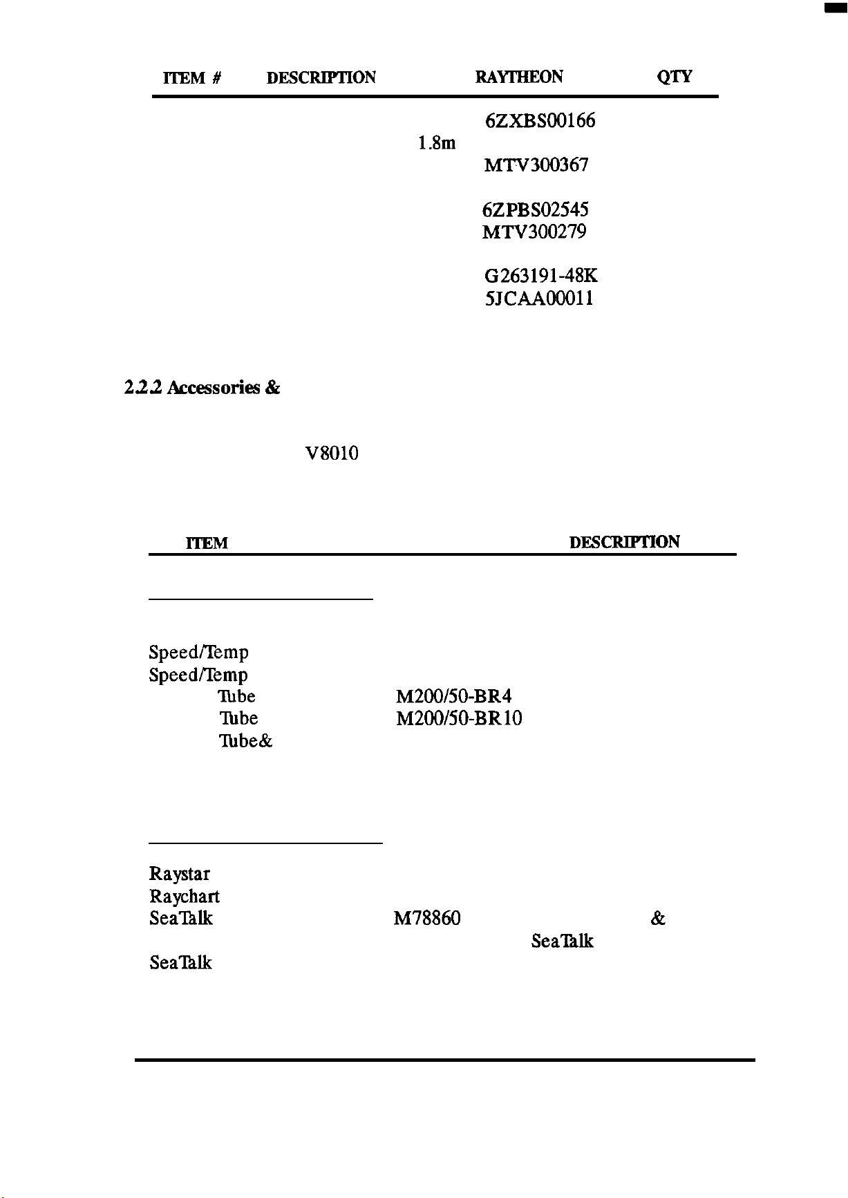
22.1 Equipment Supplied
The following items should be included in the carton with your
echo sounder unit. If an item is missing, please contact your Raytheon
dealer immediately for assistance.
V8010
is designed to the highest levels of quality and
V8010
Table 2.1 Equipment Supplied
ITEM#
1
2
or
DEXXIPTION
V8010
Transducer, Type 2528L M78858
200/50/28Khz, 1KW
Transducer, Type 2528B M78859 (Bronze)
200/50/28Khz, 1KW
Color Echo Sounder
RAYTHKON
(Lexan)
PA’ QTY
1
1
1
INSTALLATION 9
Page 18
ITEM#
DJZSCRIPTION
RAITHEON
P/N
QW
3
4
5
6
7
8
9
10
11
Spare Parts Kit
Power Cable Assy
1.8m
Sun Cover
Dust Cover
Instruction Manual
Hood
Mounting Screws
Connector, 6 pin (Data)
Connector, 5 pm,
6ZXBSOO166
CFQ-4598
MTV300367
MPXP30132
6ZPBSO2545
MT%‘300279
MPTG02024
G263191-48K
5JcAA00011
1
1
1
1
1
1
3
1
1
(Transducer)
12
Connector, 7 pm, (Video)
222 Accessories 82
TBA
Options
1
The following items are available to aid in the installation or to enhance
the operation of the
V8010
Color echo sounder unit. Please contact your
Authorized Raytheon dealer for information on obtaining any of these
items.
lTEM
PRODUCT NUMBER
INSTALLATION ITEMS:
Console Mounting Kit
Speed/Temp
Speed/Temp
Stuffing
Stuffmg
Stuffing
Sensor
Sensor SST
lube
4” Bronze
Abbe
10”Bronze
l’hbe&
Adapter Plate M78695
M78692
M78662
M78696
M200/50-BR4
M200/50-BRlO
Fairing Block M78693
Fairing Block
OPERATION ENHANCEMENTS:
Raystar 100 GPS Sensor
Raychart
Sea’Btlk
Sea’Ihlk
610ES Chart System M95990
Interface Kit
Y Cable
M78694
M95984
M78860
M81172
DJZSCRlPTION
For flush mounting
Bronze, TH Sensor
SST TH Sensor
For fiberglass boats
For fiberglass boats
For metal hull boats
For mounting 2528L
For mounting 2528B
Adds GPS Nav functions
Adds Electronic Charting
Interface PCB & kit for
Sea’IUk
network.
INSTALLATION
10
Page 19
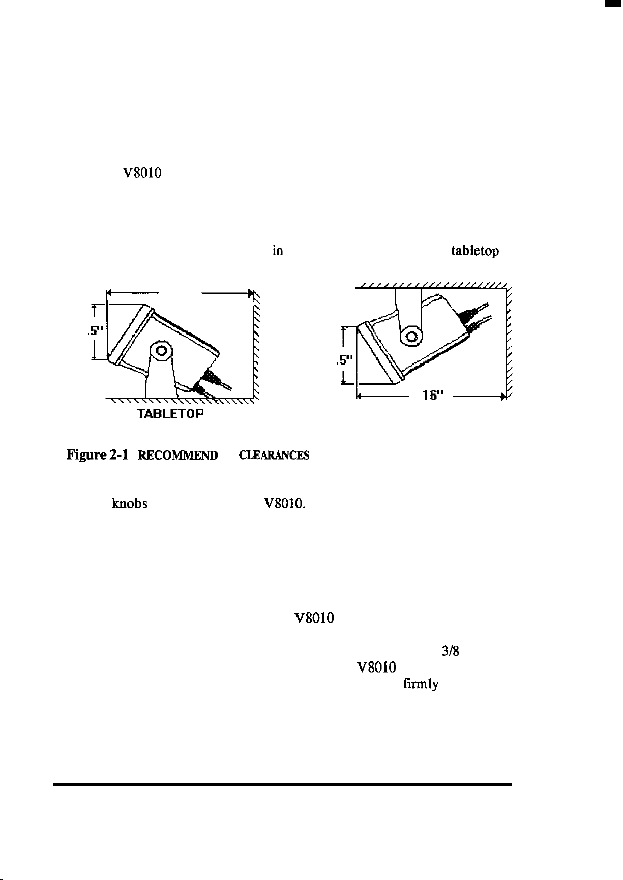
2.3 INSTALLING THE DISPLAY UNIT
23.1 Standard Mounting
The two most important considerations, when deciding on where to
mount the
l
V8010
Color echo sounder unit will be:
To choose the best location for operating and viewing.
*Best protection afforded to the unit from the environment.
Typically, the unit can be mounted iu its yoke assembly to a chart tabletop
or suspended from an overhead location,
I‘-
16”
-6
8.
8.
TABLETOP
FIgure2-1 REcoMMEND
ED
CLEARAh’CES
FOR YORE MOUNTING
OVERHEAD
To mount the unit, remove the mounting yoke from the unit by loosening
the yoke
knobs
on each side of the
V8010.
Attach the bracket to the desired
mounting surface with appropriate screws. ( included in the kit). Once the
bracket has been mounted, slide the unit back into its yoke. Secure the unit
with the yoke knobs at the desired viewing position.
232 Console Mounting
You may choose to flush mount the
V8010
display using the optional
Console Mounting Kit M78692. The Console mounting kit contains the
necessary hardware for flush mounting the unit into panels up to
in thickness. The trim riug is designed to hold the
console cutout, but it is recommended that the unit also be
V8010
in position in the
tirmly
3/g
inches
supported
inside the console to protect the unit from excessive vibration or pounding
forces.
INSTALLATION 11
Page 20
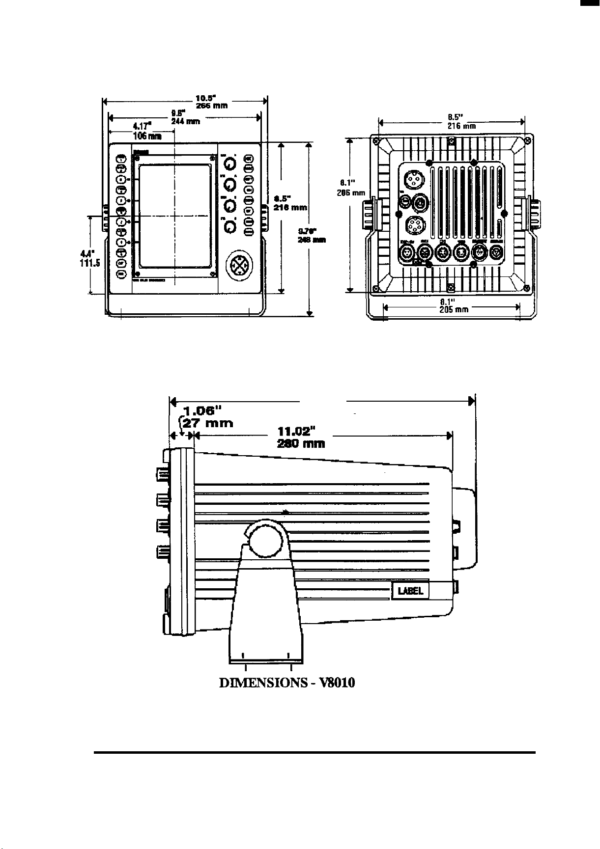
_l .m-
13.07”
332
mm
8.1”
205 mm
Y
OUTLINE
INSTALLATION 12
DIdENS~O~S - MI010
ECHO SOUNDER
Page 21
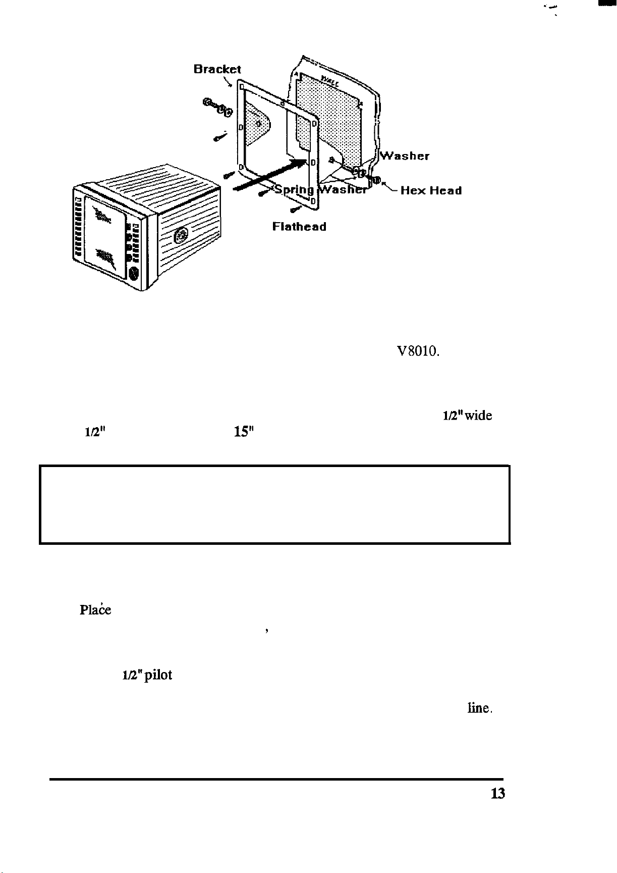
232.1 Console Mounting Instructions
Screw
Flathead
Screws
The procedure below can be used to console mount the
V8010.
Refer to
the console mounting figure above to see how the various hardware items
are arranged during assembly.
1. Select the location for the unit. A clear, flat area of at least 11
by 9
lL2”
high having at least
15”
of clearance depth behind the panel is
Wwide
required.
CAUTION
Make sure there are no hidden electrical wires or other items behind the
desired location before proceeding. Check that free access for mounting
and cabling is available.
2. Unpack the console mounting kit and confirm that all hardware is
present.
3.
Pla6e
the trim ring over the desired location on the panel. Using the
inside of the trim ring as guide , trace the perimeter for the cutout.
Remove the trim ring.
4. Drill a 1E’pilot hole in each opposing corners of the cut-out area.
5. Using an appropriate saw, cut along the outside edge of the cut-out
INSTALLATION
line.
l3
Page 22
6. Remove the yoke knobs, the yoke, and the rubber spacers from the
V8010
cabinet. Check that the unit will fit into the cut-out area.
7. Complete the installation of the DC power, transducer, data input,
ground, and any other accessory cables, into the console.
8. Slip the trim ring over the cabinet from the rear.Make sure the rounded
tabs on each side face the rear of the cabinet. Slide the unit into the
cutout of the panel. A suitable sealant may be used between the trim
ring and console panel to prevent moisture entry.
9. Use the clamps and hardware supplied in the kit to secure the unit in
the trim ring bracket. The trim ring should be then secured onto the
console with the countersunk
the unit rear panel.
2.4 CONNECTIONS
flathead
screws. Connect all cables to
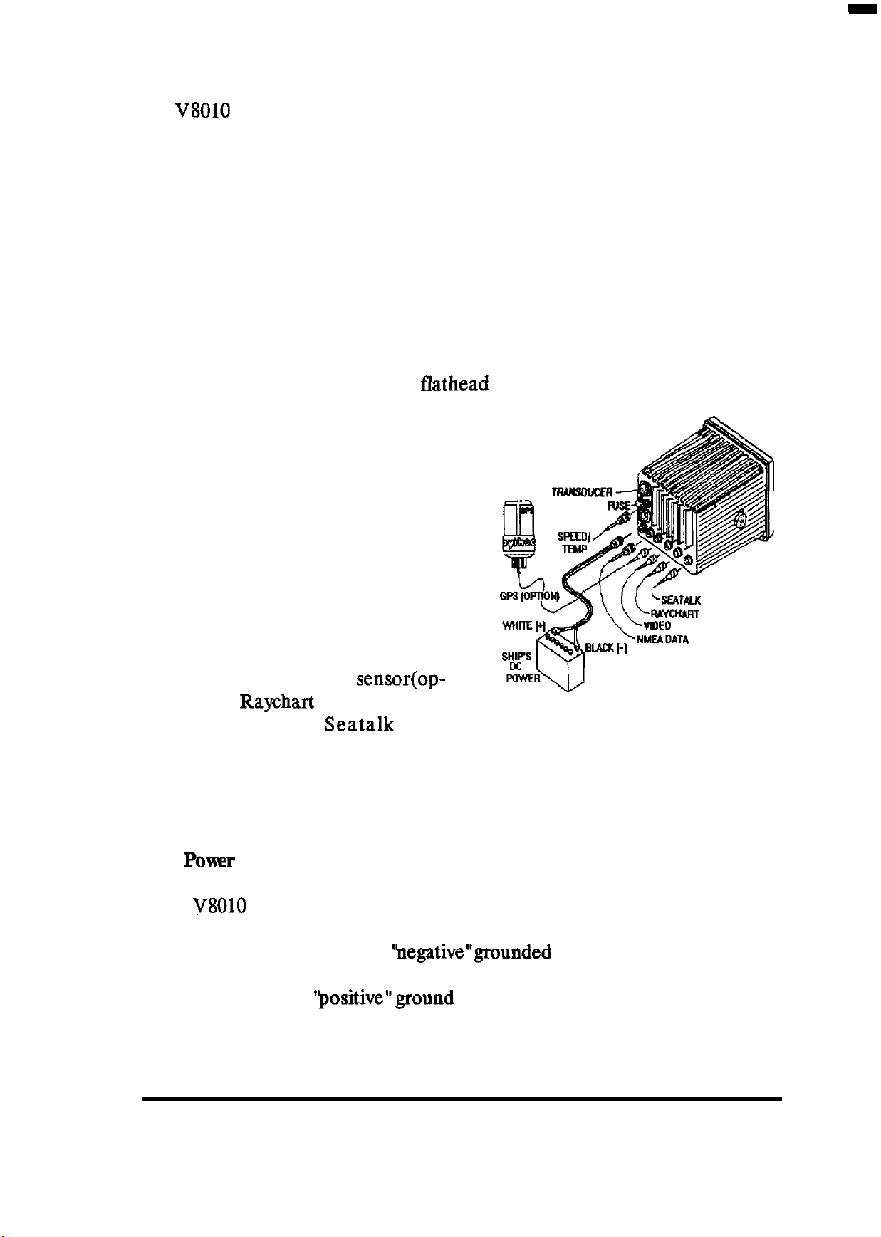
The drawing shows the basic rear
panel connections to the echo
sounder unit. In a simple installation, the connections at the left side
of the unit (power and transducer)
are used. The connectors along the
bottom provide input of NMEA
data, the GPS antenna
sensor(op-
tional), the Raychart 610ES controller (optional), or
Seatalk
data
(optional). A connector for an external RGB video output is also provided.
A grounding screw is provided to connect the echo sounder to the ship’s
RF ground system.
2.4.1
The
POWX
V8010
Input
is intended for use on vessels with DC power systems and can
operate as long as the DC supply is maintained between 10.8 to 41.3 VDC.
The DC power system can be
‘hegative”grounded
or have both positive and
negative supply lines “floating” above ground. The echo sounder is not
intended for use on ‘positive”ground vessels.
INSTALLATION 14
Page 23

A6footpowercableassemblyissuppliedwithyourunit and,inmanycases,
will be adequate to reach to the source of DC power. The 3 pin watertight
connector plugs into the rear panel receptacle in the lower left comer of
the unit marked DC 12-40V.
The power leads should normally be routed to the ship’s DC power
distribution panel on larger boats. The unit requires 5 amps of current; is
fused at 10 amps. So connection to a 10 amp or (maximum of) 15 amp circuit
breaker is recommended. On smaller vessels, the power leads may be
connected directly to the main battery isolation switch or breaker. For best
noise immunity from the other shipboard electronics avoid grouping the
unit’s power connections together with the radar, radio, or other navaids,
such as loran or GPS on the same circuit breaker. The power leads should
be separated as much as possible from other devices.
Although the unit’s power consumption is approximately50 watts, if the
power cable leads need to be extended more than 10 feet, the gauge of the
wire leads should be increased accordingly to minimize line losses. For
runs of
20-35
feet # 12 AWG is recommended.
Confirm the power leads are connected to the correct terminal polarity!
The WHITE wire should be connected to the Positive (+ ) source terminal;
the BLACK wire should be connected to the Negative (-) source terminal.
If the power leads are accidentally reversed, the rear panel fuse will blow.
If this happens, recheck the polarity of the power cord connections with a
voltmeter (VOM) and, if necessary, reverse the leads for a proper polarity
connection. Replace the fuse.
2.42
Data Input/Outputs
The
V8010
at the 6 pin connector marked
has one Data Input port and one Data Output port available
“NMEA”
located on the rear panel (next to
the Power connector). When an external navaid is connected to the Data
Input port, the
V8010
can recognize the NMEA
0182,0183,
or JRC serial
formats:
.
Ifthe
.
NMEA 0182 format, only the Latitude and Longitude of
the ship’s position will be supplied to the echo sounder to operate the
plotting mode.
.
Whenhe
.
NMEA 0183 format, the sentences GLL, GTD,
APB, VTG, BWC, RMA, RMC, and RMB can be read by the unit.
INSTALLATION 15
APA,
Page 24
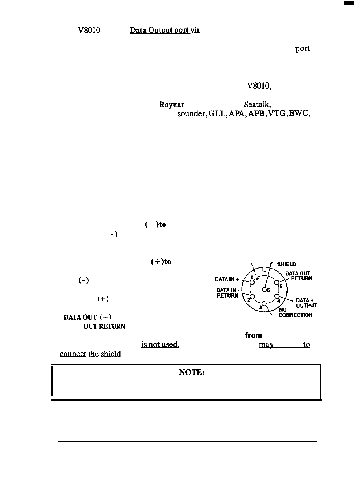
The
V8010
has one
Datavia
the same 6 pin connector which
can provide data for up to 3 external navigation equipments connected in
parallel. So, be sure that all devices connected to this data output port
(autopilots, plotters, video sounders, radars) are programmed to use
NMEA 0183 data format.
When sending the NMEA 0183 Data Output from the
V8010,
the normal
data available includes the DBT (Depth) and MTW (water temperature)
sentences. When the optional Raystar 100 GPS sensor, Seatalk, or an other
extemalnavaidisinputto the video sounder,GLL,APA,APB,VTG,BWC,
RMA, RMB, or RMC sentences are available at the Data Output port.
2.42.1 Making Data Connections
A 6 pin watertight connector is supplied with the spare parts materials for
making the Data Input/output connections. The general instructions for
assembling this 6 pin connector can be found in section 2.422 of this
chapter. If planning to use both input and output ports it is recommended
that a cable containing two (2) pair of shielded twisted conductors be used
for the interface cable.
Connect the Input Data ( +
Data Return ( - ) to pin 2 of the connector. Pin 1 is marked by the raised
)to
pin 1 of the connector. Connect the Input
dot on the housing.
Connect the Output Data (+
)to
pin 4 of
LOCATING DOT
DATA OUT
the connector. Connect the Output Data
Return ( -
DATA IN
DATA IN RETURN
DATAOUT (+)
DATA
Pin 3 of the connector
cotme& &&i&l
Do NOT GROUND the Data Output or Data Out Return lines at any of
)
to pin 5 of the connector.
(+)
OUT RETURN
= PIN 1
= PIN 2
= PIN 4
= PIN 5
is
of the data output pair of wires.
Viewed
fkom
solder side
Pin 6 of the connector map be used
NOTE:
the external navigation equipments.
to
INSTALLATION 16
Page 25
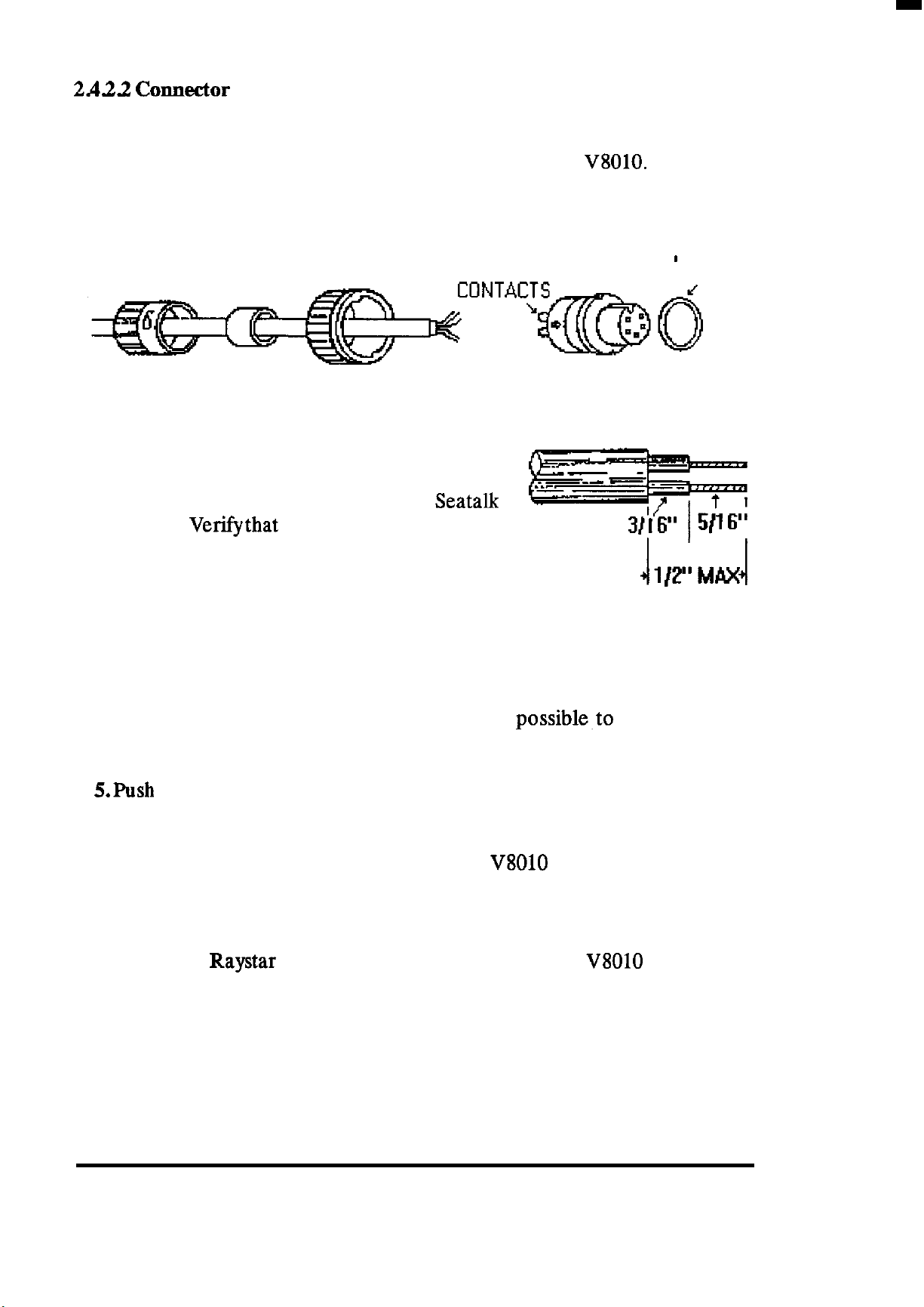
2AiU
Cormeetor
Assembly Instructions
This section describes the procedure to correctly assemble the various
watertight connectors used to connect accessories to the
V8010.
1. Feed the end of the cable through the backshell, rubber grommet and
coupling ring in the order and position shown.
BACKSHELL
GROMMET
COUPLING RING
PIN
CONNECTOR BODY
‘0 ’ RING
2. Strip cable as shown. Begin soldering con-
ductors to pins of the connector as shown in the
appropriate diagram for the NMEA, or
connectors. Verifythat each connection
Seatalk
is firmly
soldered and that no stray wires are shorting
adjacent pins.
3. Slide the coupling ring over the body of the connector and beyond the
locking projections on each side. If may be necessary to rotate the ring
slightly for it to pass by the locking tabs.
4. Push the rubber grommet forward as far as
possible~to
seat it snugly
against the connector body.
5.Push the backshell all the
way
forward. It must first compress the rubber
grommet, then be twisted over the (2) locking posts on the connector body.
This is a tight connection. For leverage, it may be helpful to first insert and
lock the connector into its mating plug on the
V8010
back panel.
2 A3 GPS Sensor (Option)
The optional Raystar 100 GPS sensor unit used with the
V8010
is not only
a GPS antenna unit, but also contains the GPS receiver/processor. Normally, the sensor obtains its 12 VDC operating
sounder
display
unit
and can then proceed to locate and track satellites and
power
input from the echo
provide ship’s L/L position data on its own without other input require-
ments.
INSTALLATION 17
Page 26
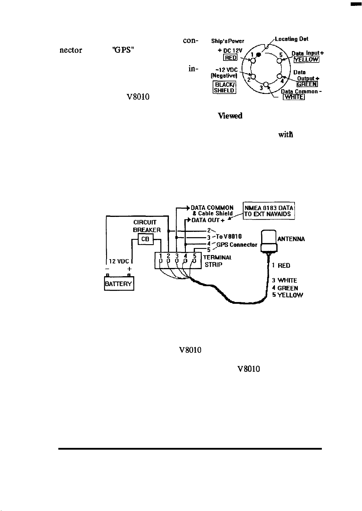
In a typical installation the 5 pm an-
tenna connector is plugged into the
nectar labeled
‘FPS”
on the rear of the
con-
cabinet. Other external navigation
equipment requiring GPS position
in-
puts normally can obtain the required
NMEA 0183 data via the Data Output
connection of the
V8010
via the 6 pm
Data cable.
Viewed
from solder side
However, there may be an occasion
where it is desirable to operate the GPS sensor unit directly
with
other
navigation equipment capable of accepting GPS input data. In this case,
the GPS sensor cable could be terminated at a terminal strip outside of the
video sounder and cabled according to the configuration shown in the
drawing below. The GPS sensor provides GLL, VTG, RMC, and GGA
NMEA 0183 sentences in it’s output.
2
BLACK/SHIELD
In this installation the ship’s DC power is applied directly to the GPS
sensor through a circuit breaker and/or distribution switch.
sensor to be used even though the
The Sensor DATA OUTPUT is provided both to the
V8010
is turned OFF.
V8010
This permits
the
GPS connector
input and in parallel to the external navigation equipment. Please note that
the GPS sensor output is only guaranteed to drive 2 (two) devices directly.
Verify also that the data lines are not grounded at any of the external
equipment.
INSTALLATION 18
Page 27
The Sensor
DATA
INPUT wire (pin 5)
should also be connected to the GPS
connector so that the echo sounder can provide initializing data input to the
GPS sensor unit.
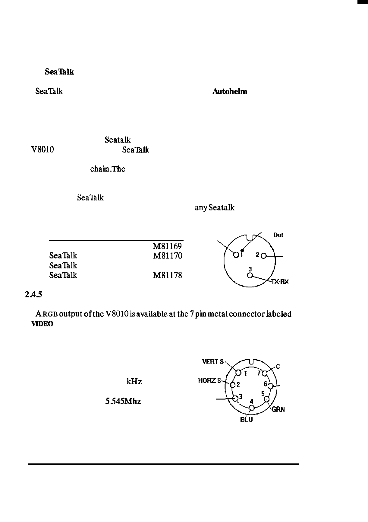
2.4.4
Sea%lk
Sea’ltilk
Interface
is a system of data interchange between
Autohelm
Instruments
and Autopilots and other Sealhlk compatible units. The system is linked
serially by a single cable containing three wires. The wires used are 1) 12
VDC supply, 2) a bi-directional data line, and 3) ground.
When the optional
V8010
is connected to the
Seatalk
SeaTalk
Interface Kit (M78860) is installed, and the
bus via the 3 pm micro connector on the
unit rear panel, the echo sounder will interface directly to the free end of
the Sealhlk data
chainThe
connections for the 3 pm connector are shown
in the diagram.
Convenient
Raytheon/ Autohehn dealers to help complete
Sea’l%lk
cable assemblies are available at various lengths from
anyseatalk
interconnection
requirements as follows:
Locating
Dot
TX-R%
Sealhlk Cable
SeaINk Cable
Sea’lhlk
Seal?&
2A5
Video Output
ITEM
LENGTH P/N
3 Foot
10 Foot M81170
Cable
30 Foot
Y Cable 1 Foot
MS1169
M81171
M81178
vcc
1 2
3
Q
[Solder Side]
View from solder side
A~~~output
VIDEO
OUT on the unit’s rear panel. This output can be used to operate a
ofthe V8010isavailableat the7pinmetalconnectorlabeled
separate remote RGB color display.
Gnd
Data
The picture will be portrait oriented on the
remote display.
Horizontal Sync = 15.75 kHz
Vertical Sync
Dot Clock
= 60Hz
=
5.545Mhz
VIDEO OUTPUT
VERT
S
1 7
HORZS
GND
0
2
32
6
BLU
View from solder side
INSTALLATION 19
CLOCK
RED
GFIN
Page 28
2 A.6
Grounding The Echo Sounder
One very important requirement in installation of shipboard electronics
is to obtain the cleanest, noise-free environment possible so each piece of
electronic equipment can work to its best performance levels. This requirement isaccomplished byassuringaproper connection from each equipment
to the ship’s RF ground system. The ground provides a drain for shipboard
noise transmission and pickup.
A separate ground wire of # 10 or # 12 AWG (# 10 recommended) should
be connected from the ground screw marked
“E”on
the rear of the unit to
the nearest connection point of the ship’s ground system.
Normally,on a steel hull
boa&a
good clean connection to the hullprovides
a sufficient ground. On a fiberglass or wood hull, connection to a ground
plate or to the engine block and other bonded groundwork should be
acceptable.
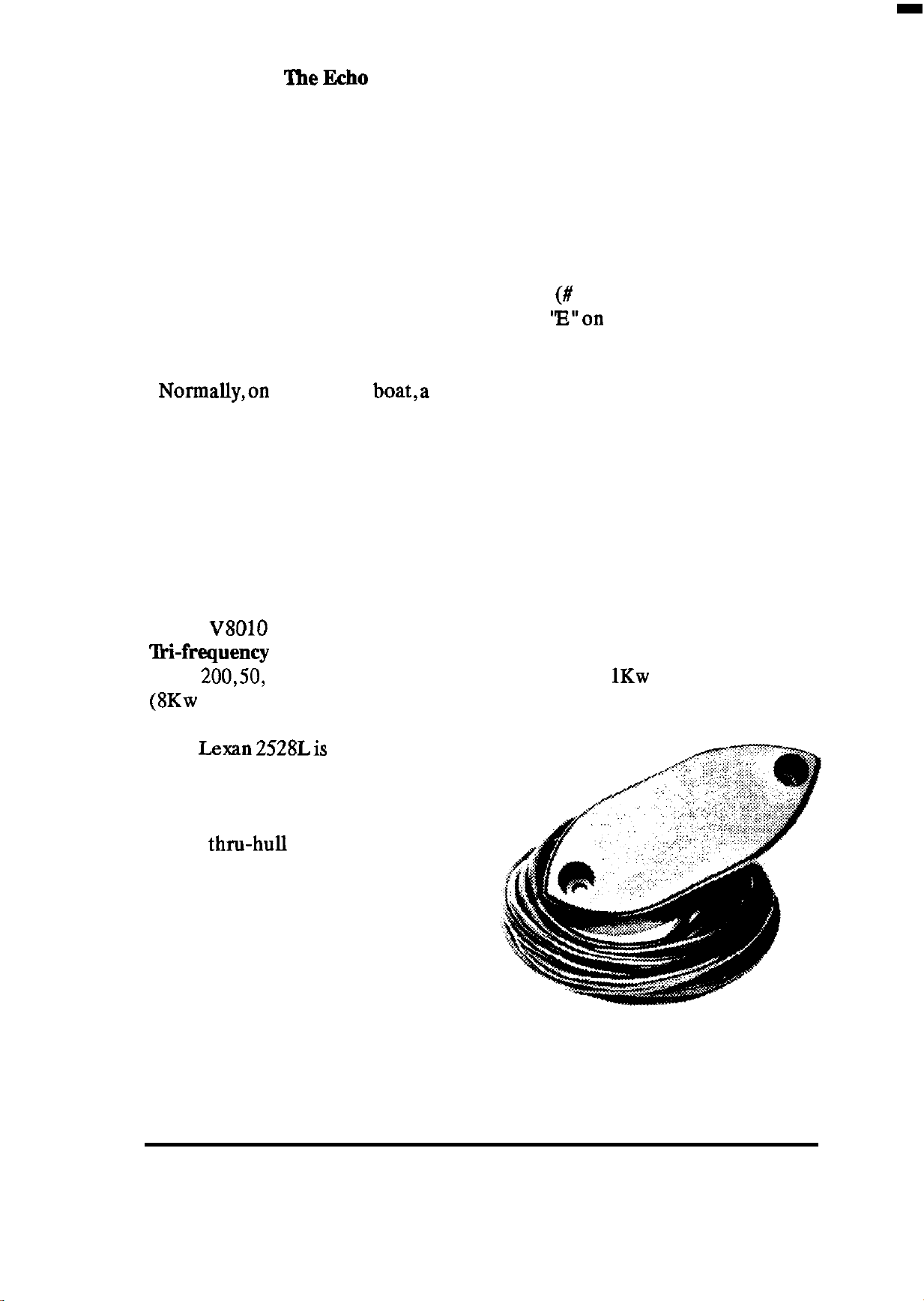
2.5 TRANSDUCER INSTALLATION
25.1 General Information
Each
‘B&frequency
ate at
(8Kw
The
V8010
200,50,
peak).
Lexan
Color Echo Sounder is provided with one of the new 2528
transducer assemblies. The ‘Iii-frequency transducers oper-
and 28Khz frequencies and are rated to
1Kw
ofaverage power
2528Lis intended for direct
hull mounting with thru-bolts and a
stuffing tube, while the 2528B bronze
transducer is used when the more traditional thrn-hull stem mounted style is
preferred. Stuffing tubes for the 2528L
for use in wood, fiberglass, or steel ves-
sels and fairing block assemblies suitable. for both transducers are available,
as options, from your Raytheon dealer
to simplify installations. (See Options
list)
INSTALLATION 20
Page 29
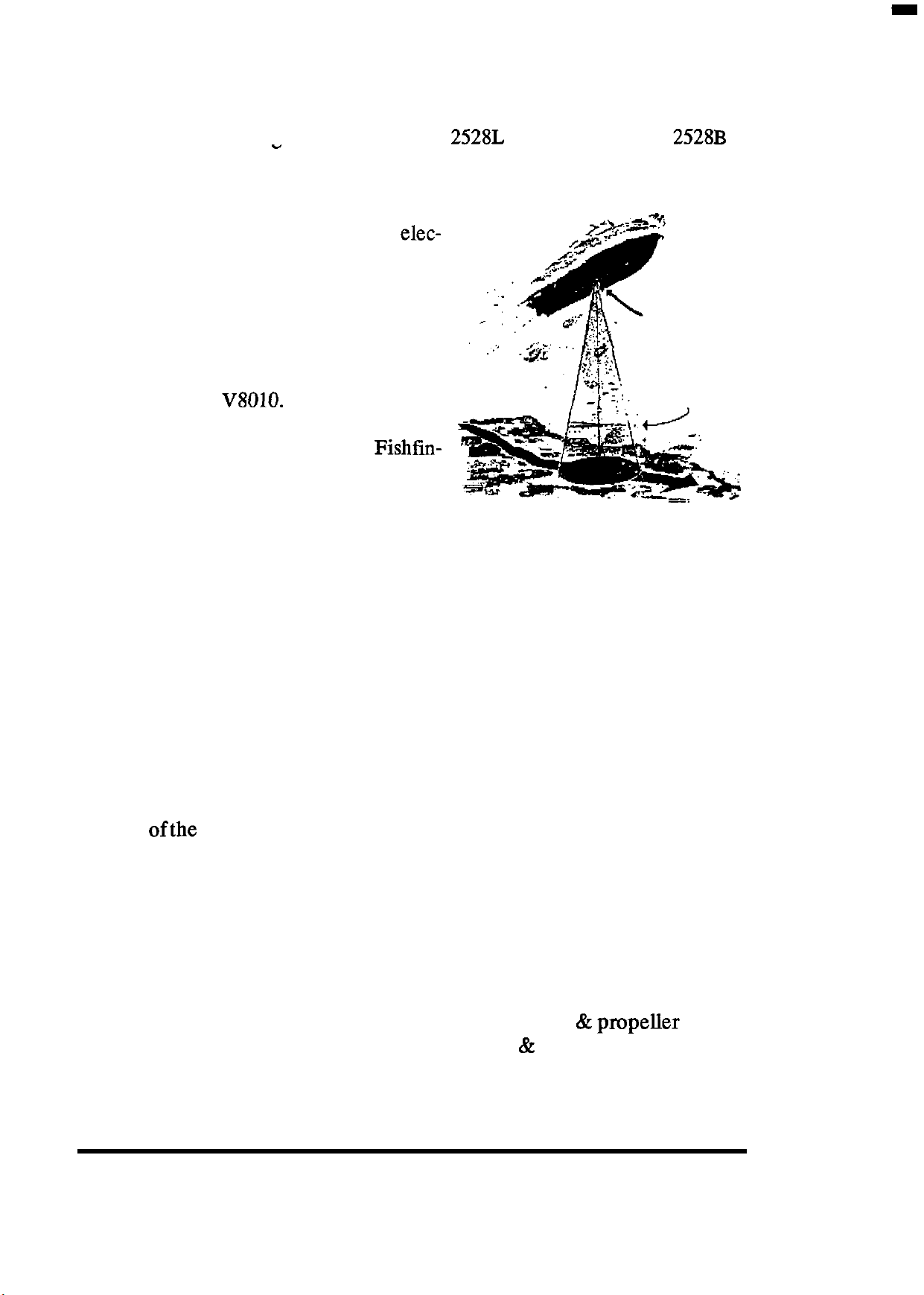
The transducer section of the manual begins with a general discussion of
transducer installation considerations for locating transducers on the ves-
sel. Detailed mounting instructions for the
follows this section.
-
2528L
transducer and the
2528B
The transducer element is that portion
of a sounder system that converts the elec-
tricalpulse from the sounder into a sound
wave which is transmitted downward to
the bottom and returned as an echo. This
TRANSDUCER
echo is picked up by the transducer and
sent to the sounder which, through time
comparison, converts the difference for
display on your
V8010.
ENERGY WAVE
The transducer, the heart of the Fishfin-
der, is a delicate instrument and although
it is designed to survive in the toughest
marine environment it should not be
dropped or manhandled during installation.
The transducer element assemblies are constructed into either molded
resin or bronze caste housings and covered with an epoxy window surface.
The epoxy “window” is the surface through which ultrasonic pulses must
travel. This epoxy surface must be kept as clean and smooth as possible so
the ultrasonic energy path is uninterrupted. Caution is advised when han-
dling the transducer to prevent any damage to the transducer face.
Also, when handling the transducer, avoid lifting or pulling on the
transducer by the cable. Although the cable appears thick and substantial,
the internal cable wiring could become damaged due to stress by the sheer
weight
ofthe
transducerunit and malfunctionat the most inopportune time.
252 General Mounting Considerations
In any transducer installation acoustic noise is always present. The noise
is usually a combination of “ambient” as well as “vessel generated” levels.
Ambient noise is often generated by waves and air bubbles, fish and mam-
mals, ram and hail on the surface, other nearby vessels or shore noises.
Sources of vessel generated noise include: propellers
&
propeller shaft
vibrations, machinery, main engines, generators & pumps, flow of water
INSTALLATION 21
Page 30

across the hull, boundary layer turbulence, and interference from other
onboard echo sounders.
While very little can be done to combat ambient noise, carefully selecting
the transducer mounting location can help to minimize the influence of the
“vessel generated” noise. Of course, the lower the acoustic noise level; the
better the signal-to-noise ratio and the higher the echo sounder gain setting
that can be used.
Mounting Location-Displacement Hulls
Study the shape of the vessel hull carefully to determine the best
transducer mounting location. To achieve optimal echo sounder system
operation, the transducer should be mounted in a spot which will minimize
acoustic noise reception and the chance that aerated water will flow across
the transducer’s acoustic window (transmitting surface).
One of the main sources of vessel generated noise is from the propeller.
It is very important to pick a mounting position to keep the transducer
clearly away from this noise source to minimize pickup.
As an additional precaution tilt
the transducer forward slightly so
that the transducer acoustic win-
dow is facing away from propeller
noise.
Generally
a
5’ forward tilt is
recommended. Any tilting is normally accomplished in the shaping
of the fairing block.
Mount the transducer on the side
of the hull where the propeller
blades are moving downwards.
The upward motion of the propeller generates pressure waves
which pushes air bubbles up
against the hull. By mounting the
transducer on the downward side,
the hull will tend to protect the
transducer from this effect.
INSTALLATION 22
Page 31

Aerated water can blind an echo sounder by reflecting the ultrasonic
energy. Water near the bow and water near the keel can become quite
aerated. Aeration occurring near the transducer can be minimized by
keeping the transducer mounted away from the keel, and by mounting the
transducer in the after
and water line, if possible.
2/3
of the vessel’s length midway between the keel
Generally, this provides the best compromise
between obtaining aeration-free water and minimizing propeller noise.
Keep in mind that the deeper the transducer protrudes into the water, the
less chance of aeration.
NOTE:
The transducer should not be mounted near any water discharge fittings.
Never position a transducer behind any struts or fittings that may cause
turbulence.
BOLT HOLES (2)
34’
(1Om)
0.40” dia.
39”
OUTLINE
DIMENSIONS
2528L
LEXAN TRANSDUCER
INSTALLATION 23
Page 32

2.53
2528L Lexan
Transducer Installation
253.1 Preparation 1 - The Stuffing
M200/50_BR4
M200/5O_BRlO
Other stuffing tubes can be used but special care must be taken to insure
these tubes will sealproperly to the
These instructions are written speciflcallyto facilitate installationsusingthe
Raytheon optional stuffing tubes.
10” Bronze
lbbe
Installation of the 2528L lexan
transducer requires a
of a material compatible with the
hull. Raytheon offers bronze stuffing tube kits for wood or fiberglass
(GRP) hulls as well as a stuffing
tube kit and adapterplate for steel
hull mounting. Stufling tubes for
wood or fiberglass hulls can be
ordered by the following numbers
from your Raytheon dealer:
4” Bronze Stuffing
Stufling ‘Inbe
0.40”cable
diameter
lltbe
ofthe
stufling
transducer.
tube
2532 Preparation 2 - The Fairlng Block
Nearly all vessels have some
location. If the transducer were mounted directly to the hull, the sound
beam will be tilted off from the vertical at the same angle as the deadrise.
A fairing block (usually constructed of wood such as mahogany or teak)
providing a level mounting
surface is strongly recommended. A Resin Fairing
Block (Product # M78693)
for use with the
transducer is available from
your Raytheon dealer for
convenient installation.
2528L
deadrise
angle at the transducer mounting
INSTALLATION 24
Page 33

To
reduce drag, best results are obtained with sharp vertical leading edge
fairings because their wedge shape helps to divert aerated water off to the
sides of the transducer and not over the acoustic window.
After the fairing block has been shaped to the
mm x 150 mm
(3”~
6’3 hole should be cut through the center of the fairing
deadrise
of the hull, a 77
block to allow for cable routing and service loop, and to make room for the
stuffing tube that leads the cable into the hull.
Backing blocks should be fabricated using the interior deadrise angle on
bottom of block and a level surface on the top of the block for mounting
hardware for each of the two rods that hold the transducer in place. Boat
yards are generally equipped to fabricate fairing and backing blocks.
Place the transducer over the fairing block and mark the two transducer
mounting hold locations. Drill the two 10 mm
through the fairing block. Counterbore these holes to 39 mm (1
diameter, 10 mm
(13/32”)
deep, from the transducer side.
NUT, AND WASHERS
(13/32”)
LESS STEEL ROD
diameter holes
112”)
BOLTS SHOULD BE TORQUED
TO NOT MORE THAN
TRANSDUCER
TYPICAL LEXAN TRANSDUCER
2533 Preparation 3 -
The
Location.
FAMNG
RUBBER WASHER
INSTALLATION
BLOCK
(For Fiberglass or Wood Hull Installation)
(Safety Goggles and Dust Mask should be worn when drilling)
10
Ff/LBS
INSTALLATION 25
Page 34

A. Drill a
Gaugingwhere the transducer mountingrods
‘l&sting
Hole Location For The Stuffing
willgo,
lbbe.
see
ifthere
is a strake
or other hull irregularity near the hardware sites for rods and stuffing tube.
If no possible interference is apparent from inside the hull, or outside the
hull, drill a 3 mm
you mayhave to select another
(l/S”)
diameter pilot hole. If a restriction is encountered,
location.
Note that sometimes you may have
to drill from the outside of the hull.
B. Stuffing
Drill a 28 mm (1
the
stufling
‘lbbe
Hole Preparation:
l/S”)
hole perpendicular to the outside hull surface for
tube from the outside
ofthe hullat
pilot hole location. Remove
all burrs and clean the area around the hole, inside and outside, to ensure
that the caulking will seal. It is important that the circumference of the
flanged nut that secures a non-welded stuffing tube from inside the hull be
in contact with the hull surface. Shims may be required.
C.
‘Ikansducer
Drill two 10 mm
Mounting Hole Preparation:
(13/32”)
holes in the hull and in the backing blocks for
the transducer mounting rods. To reduce drag, care must be taken to ensure
that the two rod holes are drilled parallel to the keel to maintain the
alignment of the transducer fore and aft.
Note that the 2528L housing is
symmetrical and either end of the transducer could be positioned forward.
253.4 lkansducer Installation
The order of assembly for the transducer is to first mount the
stuffing
tube
into the hull. Follow by mounting the fairing block and backing blocks to
the hull with the two stainless steel rods provided. Finally the transducer
gets bolted onto the hull. Each step is
detailed in the following paragraphs.
1. Install The Stuffing
lbbe
First.
Remove the rubber bushing, washer
and packing nut from the stuffing tube.
Select a marine grade polysulfide, urethane or RTV bedding/caulking compound for sealing the units to the hull.
Following the recommendations of the
caulking compound manufacturer,apply
a 3 mm
the
(118’3
stuffing
thick layer of caulking on
tube flange that makes con-
tact with the outside of the hull, and up
INSTALLATION 26
db-
Packing Nut [Bmnze]
Washer
Rubber Bushing
Washer
Ftanged
Vessel Hull
Stuffing
[SSTj
ISSTJ
Nut @ronze]
wood
or
Fiberglass]
Tube @mnze]
Page 35

the threads of the stuffing tube to where the flanged nut will be, inside the
hull. This will seal and hold the flanged nut securely in place inside the hull
Push the stem of the stuffing tube through the hull and fasten the bronze
flanged nut from inside the hull. For a fiberglass hull, tighten this nut
securely.
NOTE:
If the hull is wood and has been out of the water for a prolonged period,
it is suggested that the stuffing tube nut be hand tightened only, since wood
will swell after the boat is in the water and exert considerable pressure on
the stuffing tube hardware. After the hull has expanded, the nut should be
tightened securely.
2. Install the
Faking
Block:
Slide a backing block, washer, and a nut onto each of the threaded rods.
Feed the rods down through the hull.
Cut a piece of tarred felt (not provided) as a gasket to fit between the hull
and the fairing block (see the figure below). Cut a hole in the center of the
felt for the cable to pass through.
Following the caulking manufacturer’s directions, apply 3 mm
(l/S”)
thick layer of caulking to the surface of the fairing block that fits against
the hull. Lay the tarred felt on top of the coated fairing block.
ST Threaded rod, nut
&
washer (2 sets]
ST Nut &washer
ubber
Leveling
ANOTHER LOOK AT A TYPICAL INSTALLATION
washer
Sealent
INSTALLATION 27
Page 36

From outside hull, slide fairing block up onto the threaded rods, and press
up against the hull. Verify that the length of the rods extending below the
flat face of fairing block is between 2.75” to 3” in length. If not, adjust by
tightening the nuts on the rods inside the hull to obtain this length.
Secure the fairing block to hull using a stainless steel washer and nut on
each rod as shown in the figure. Tighten the nuts with a torque wrench using
a force not exceeding 5
used, tighten the nuts only lightly. This will allow the fairing block to
in sea water and then the internal nuts at the backing blocks may be
tightened to 5
ft./lbs.
ft./lbs
(7 newton-meters). If a wood fairing block is
(7 newton-meters) for proper torque.
swell
3. Route Cable through the
Stuffing ‘Ibbe.
Uncoil and thread the transducer cable through the stuffing tube to the
inside of the hull. Make a service loop inside the cavity of the fairing block
so there will be no tension applied to the cable.
IMPORTANT
When handling the transducer and cable
msducer
m
by its cable because this may sever internal connections and
hold the transducer in place during transducer mounting by applying
NOTE
do
tension to the transducer cable.
4. Caulk the Fair-lug Block.
Following the manufacturer’s directions, apply
l/8”
(3 mm) thick layer of
caulking to the surface of the fairing block that will be in contact with the
transducer.
5. Mount the transducer.
While holding the transducer in position against the fairing block, slide a
rubber washer and a stainless steel washer (provided) onto each transducer
mounting rod. Apply some caulking to the mounting rod and then secure
the transducer with nuts provided. Tighten the nuts with a torque wrench
using a force not exceeding 5
minimum of 3 threads extending beyond the head
ft./lbs
(7 newton-meters). There should be a
ofthe
nut when tightened.
WARNING:
DO NOT USE SOLVENTS
Do not expose the 2528L resin transducer to any solvents while cleaning
away excess sealants. Strong solvents such as acetone and methylene
chloride will attack many types of plastics and can dramatically reduce the
strength of those materials. Accumulation of grease or grime should be
removed with a soft damp cloth and
mild detergents.
INSTALLATION 28
Page 37

6. Seal Cable in
Stuffing lbbe:
Slide the rubber compression bush-
ing, compression washers, and the
packing nut down the
to the
stuffing
tube (see Figure 5).
Make sure the rubber bushing fits
transducer
cable
se-
curelyinto the machined upperpart of
the
stufling
tube. Tighten the packing
nut. Clean up all excess sealant material inside the hull.
7. Plug the bolt holes.
To minimize turbulence on the
sur-
face of the transducers, a white Styrofoam plug material is supplied which
fits into the transducer mounting holes. Cut the Styrofoam to length so that,
when installed, each plug is recessed 5 to 7 mm
(3/16”
to
5/16”)
below the
surface of the housing. Push these Styrofoam plugs into the holes and
smooth out the surface using caulking. Level out and remove any excess
caulking to ensure smooth water flow over the transducer.
8. Route the cable to the echo sounder.
Be
very
careful
not to tear the cable jacket when passing the cable through
bulkheads, etc. To reduce electrical interference, keep the transducer cable
separated from electrical wiring and other sources of electrical interference. To prevent damage, secure the transducer cable in place using tywraps
or lacing twine.
9. Attaching the plug.
The wires of the cable must now be soldered to the 5 pin transducer
connector, packaged with the echo sounder using the color code shown in
the drawing.
10 05
’
20
0
(SOLDER SIDE)
04
30
=Qdii
TRANSDUCER
P/N
HS-21P-5.5 PIN
0
0
‘1;;:
:s:
:-:
<a:
z:
COLOR
YELLOW
BLUE
SHIELDS
BLACK
BROWN
s
-7
PIN
5JcAAooo11
1
;
4
5
.
-I”,‘,”
I
;rz
’
INSTALLATION 29
Page 38

The cable can be cut to the necessary length or extended as required. If
extending the cable, use the same type of cable and conductors to complete
the installation properly.
10. Checking for Leaks
When the boat is placed in the water, immediately check around the bolts
that fasten the transducer to the hull and around the
stuffmg
tube for leaks.
Note that very small leaks may not be readily observable, so it is best not to
leave the boat in the water unattended for more than 3 to 24 hours before
checking it again. If there is a small leak, there may be considerably water
accumulation after 8 to 24 hours. If a leak is observed, the installation
bedding procedure should be repeated to seal the leak. It is not prudent to
installa
transducer and leave a boat in the water
unchecked
for severaldays.
2535 Inside the
Hull
Installations (Fiberglass Hulls Only)
Generally, inside-hull mounting can be useful on fiberglass hulls when the
top speed of the boat is at least 25 knots and drag becomes a factor. Inside
mounting creates less turbulence and the transducer performance can
improve at speeds above 20 knots. However, inside hull mounting frequently results in ultrasonic energy losses of up to 50% or more. So the
transducer must be located where hull is solid fiberglass resin to minimize
sound transmission losses.
Generally its better to test selected areas of the hull
the transducer by
placing
the transducer face against the hull and operating
first
before installing
the echo sounder while checking for satisfactory echo returns. A coupling
medium, such as water, or gel, (Vaseline), should be used to transfer the
sonic energy to the hull more efficiently during the testing. Consult with the
boat dealer or vessel manufacturer if your not sure of the hull construction
or best locations.
Once a satisfactory location is found, always mount the transducer into a
liquid-filled box. Never bond the
25281,
resin housing directly to the hull.
253.6 Steel Hull Installations
For steel hulls Raytheon offers the optional transducer installation kit
M78695 consisting of:
INSTALLATION 30
1 each
2 each
1 each
Steel adapter plate
3/8”
(9 mm) x 1 l/2” (38 mm) SST bolts
SST
stuffing
tube assembly
Page 39

Compression Bushing
Washer, SST
Steel Hull
Weldment
Pr’ard
Weld all around
SST Packing Nut
SST Adapter Plate
Cable Service
Supplied)
LooP/~~&~
Weld all around
SST Nuts, welded
to plate. [4 Places)
TYPICAL STEEL HULL MOUNT WITH CONDUIT
Note:
Certain approval authorities require that the transducer cable be encased
in conduit. In such installations, the conduit is welded to the stuffing tube,
as shown in the figure above. In welded conduit installations, the stuffing
tube must have the packing nut tightened from outside the hull. The
stuffing tube supplied by Raytheon is “reversible”, allowing the compression bushing to be tightened from inside or outside of the hull.
Once the location for the transducer has been determined, it will be again
necessary to assure the transducer is angled to face the sea bottom directly.
On steel hulled
vesselsa
steel weldment must be fabricated
bythe
shipyard
or procured by the person installing the transducer. The exact dimensions
of the weldment are not specified, but the bottom of the weldment must be
parallel to the water surface, (slightly angled forward about
5’)
and must
be large enough to allow the mounting of the adapter plate.
The weldment should also have an access hole at least as large as the hole
in the adapter plate to allow feeding of the transducer cable up to and
through the stuffing tube. Any sharp edges on the weldment and any weld
spots should be ground smooth to minimize the chance of tearing or
abrading the transducer cable. The adapter plate can either be welded
directly to the weldment or bolted to the weldment at the four places drilled
in the adapter plate. The dimensions of the vertical sides of the weldment
will be determined by the
deadrise
of the hull at the location where the
INSTALLATION 31
Page 40

Weld all around
Stuffing Tube [Steel]
Weld all around
Sealant
Rubber washer
SST
3/8
Bolt
&
washer
Styrofoam Plug
Leveling Sealant
transducer will be installed and to allow clearance for the bolts used for
attaching the adapter plate.
253.6.l
1. Inspect
Installing the
Location:
Stuffing ‘Ihbe
Prior to drilling or cutting from the outside of the hull, the interior of the
hull should be inspected to ensure that there is proper clearance for the
stufting
drilling. The stuffing tube is 150 mm
thickness of the hull, will require at least
tube and that there are no cables or stakes to impede the cutting or
(6”)
in length and, depending on the
200
mm
(8”)
of clearance to
facilitate routing of the cable.
2. Drill the Hole:
Drill or cut (with a cutting torch) a 38 mm (1
installation of the
stuffing
tube. A fire watch should be stationed inside the
l/2”)
hole in the hull for
hull.
3. Install the
‘Abbe:
Remove the packing nut, compression bushing, and washers from the
stuffing tube. These will be necessary at a later time to seal the stuffing
tube, after the transducer cable is fed up into the hull. Insert the
stufling
tube into the hull and weld the stuffing tube in place (See Figure).
INSTALLATION 32
Page 41

Cable
SST Packing Nut
SST Washer
Rubber compression
bushing
SST Washer
Steel Hull
Weld all around
253.63 Installing the Adapter Plate &
1. Mounting the Plate:
‘ikausducer
Weld or Bolt the adapter plate to the leveling weldment. If the adapter
plate is bolted to the weldment, coat the adapter plate surface that will
contact the weldment with approximately a 3 mm
(l/S“)
thick coating of
caulking. Apply caulking to the four bolts (not supplied) and install the
adapter plate to the weldment. Remove excess caulking.
2. Mounting the
Uncoil the transducer cable and feed it up through the adapter plate, the
‘Ikausducer:
weldment, and stuffing tube into the inside of the hull. Never pull of carry
the transducer by its cable---this may damage internal connections. Do not
hold the transducer in place by applying tension to the transducer cable.
Apply a 3 mm
(l/8”)
thick layer of caulking to that surface of the transducer
which will contact the adapter plate. Slide the rubber washers (to reduce
stress concentration in the resin
housing
in
the bold hole area) ,and stainless
steel washer supplied with the transducer onto the transducer mounting
bolts and then apply caulking to the threads of the two
3/8”
x 1
l/2”
long
stainless steel mounting bolts. See the figure above for the correct orien-
tation of the washers.
Holding the transducer against the adapter plate, thread the mounting
bolts into the adapter plate. Tighten the bolts with a torque wrench to
ft./lbs.
(7 newton-meters). Remove excess caulking.
INSTALLATION 33
5
Page 42

To minimize turbulence on the surface of the transducers, a white
styro-
foam plug material has been provided which fits into the transducer mounting holes. Cut the styrofoam to length so that, when installed, each plug is
recessed 5 mm
(3/16”to 5/16”) belowthe
surface
ofthe
housing. Push these
Styrofoam plugs into the holes and smooth out the surface using caulking.
Remove excess caulking to ensure smooth water flow over the transducer.
3 Finishing Details
Slide the rubber compression bushing, compression washers, and the
packing nut down the transducer cable to the stuffing tube (see the figure
above for orientation). Make sure the rubber compression
bushmg
fits
securely into the upper part of the stuffing tube. Tighten the packmg nut.
Do not apply a force exceeding 3
ft./lbs.(4
newton-meters).
Route the transducer cable to the echo sounder, being careful not to tear
the outer jacket when routing the cable. To reduce electrical interference,
keep the transducer cable separated from other electrical wiring. Secure
the transducer cable in place. To prevent damage, use tywraps or lacing
twine. Refer to page 29 for making the wire connections to the plug.
25.4. The
2528B
Bronze’Ilansducer
IMPORTANT--Please read these di-
rections completely before proceeding
with the transducer installation.
l
Do not use a bronze transducer
housing in an aluminum hull
because electrolytic corrosion
will occur.
l
If you have a cored hull, Cored
Hull installation instructions are
available from your Raytheon
dealer.
25A.l Locating the 2528B
The basic rules for locating the 2528B transducer will be the same as those
already discussed for the 2528L. See section 2.52 (page 21). However, due
to the long stem, it is very important that the mounting location have
INSTALLATION 34
Page 43

reasonable access from inside the vessel, since you must allow for the height
of the stem projecting inside the hull and still have room to tighten the nut
from inside the hull. Plan accordingly.
11.81"-
3cmmm
f?
7_48”
190 mm
3.42”
87 mm
4
25A2
2528B BRONZE
Preparing for Installation
Useful materials to have available for the installation are listed below for
your convenience:
1. Variable speed electric
2.
1/8”(
mm) Drill
(3/16”or 1/4”can
drill---3/8”
or larger, chuck capacity.
also be used).
3. 7/8”Hole saw or spade bit. (Most stem transducers require a 7/8”hole,
however, larger commercial stem transducers may require a 1’ hole.
INSTALLATION 35
Page 44

4.
Marine Bedding/Sealing Compound; use
RTV types only. (Boatlife’s Liieseal caulk is a good choice.)
25A2.1 Fairing Block
polysulfide,
polyurethane or
Nearly all vessels have some
location. If the transducer were mounted directly to the
beam will be tilted off from the vertical at the same angle as the deadrise.
A fairing block (usually constructed of wood such as mahogany or teak)
providing a level mounting surface is strongly recommended. A Resin
Fairing Block (Product # M78694) for use with the 2528B transducer is
available from your Raytheon dealer for convenient installation.
25.422 Hole Drilling
1.
Start by drilling a
access to tighten the housing nut and clearance for the cable. If there is a
strake or other hull irregularity near the mounting location, it may be
desirable to drill from the outside. (If the pilot hole is drilled in a wrong
location, drill a second hole in a better location. Apply masking tape to the
outside of the hull over the incorrect hole(s), and
2.
Using a
hull. (For personal safety, use safety goggles and dust mask.)
718”
hole saw or spade bit, drill the hole from the outside of the
l/8”
deadrise
( mm) pilot hole from inside the hull to assure
angle at the transducer mounting
hull,‘the
lill
with epoxy.)
sound
3. Sand or clean the area around the hole, inside and outside, to assure
that the sealing compound will adhere properly to the hull. If there is any
petroleum residue inside the hull, remove it with a solvent such as lacquer
thinner, acetone or alcohol before sanding. (Make sure area is well venti-
lated since fumes from many solvents are toxic and/or flammable. Refer to
safety information appearing on the solvent container.)
25.423
1. Remove the skirted nut from the transducer housing and cable.
2. Uncoil the transducer cable and thread the transducer cable through
the fairing block and fish the cable into the inside of the hull. Never carry
the transducer by its cable or hold the transducer in place by applying
tension to the transducer cable.
2528B
Installation
INSTALLATION 36
Page 45

3. Apply a
l/8”
( mm) thick
layer of sealant on the surfacesof
the transducer and fairing block
(if used) which mate with each
other and to the hull, and bronze
housing (see the figure). A thin
layer should also be applied up
the sidewalls of the stem to a
height of
1/4”(
mm) greater than
the hull plus fairing block thick-
ness. This will ensure there is
sealant material in the threads to
seal them and hold the housing nut securely in place.
4. From the outside of the hull, push the housing (with sealant applied)
into the drilled hole. Apply a twisting motion to the housing to squeeze out
excess sealants while taking care to align the transducer
assembly
parallel
to the keel. Verify the transducer and fairing block are seated to the hull
and the transducer is also pointing straight down to the sea bottom.
5. Slip the backing block onto the transducer stem and coat the surface
contacting the hull interior with the caulking compound. Tighten the hex
nut with a wrench or large slip-joint pliers. (Allow for swelling on wooden
hulls.)
6. From the outside, remove excess sealant to assure smooth water flow
over and around the transducer.
7. Route the cable to the echo sounder, being very careful not to tear the
cable jacket when passing the cable through bulkheads, etc. To reduce
electrical interference, keep the transducer cable separated from ignition,
tachometer, alternator or other electrical wiring. Secure the transducer
cable in place to prevent damage using tywraps or lacing twine.
8. Attach the 5 pin connector to the cable as shown on page
25A2.4
When the boat is placed in the water,
Check For Leaks
E%MEDIKl’ELY
thru-hull for leaks. Note that very small leaks may not be readily
21.
check around the
observed.
It is best not to leave the boat in the water for more than 8-24 hours before
checking it again. If there is a leak, there may be considerable water
INSTALLATION 37
Page 46

accumulation after 3-24 hours, (probably not enough to cause any damage).
If a leak is observed, the installation
immediately. It is not prudent to install a
water unchecked for several days.
255
bedding
procedure
thru-hull
should be repeated
and leave a boat in the
Installing the SpeerYIWperature Unit
The optional Speed/Temperature sensor unit
can be supplied in two versions. They are:
M78662 Bronze TH Speed/Temp Unit
or for metal hull installations
M78696 SST TH
Speedmmp
Unit
Externally the unit should be positioned clear
of other hull f and penetrations to avoid the
influence of hull currents on the speed readings.
The sensor should never be positioned in front
of a depth transducer, since the turbulence cre-
ated bythe paddle wheel can
ante,
especially at higher speeds of the vessel.
adversely
affect
the depth transducerperform-
Internally, the unit will need to be mounted where sufficient room exists
to tighten the flanged nut assembly and will allow clear removal of the
paddle wheel assembly for routine maintenance.
255.1 Installation
Once the location is determined, the following steps can be used to install
the sensor:
1. Drill a
2. If OK, drill a 2” hole using a hole saw from outside of the hull.
l/4”
test hole to verify positioning is suitable.
3. Unscrew the cap nut and remove the sensor assembly from the bronze
housing by pulling up on the top ring. Lay the sensor assembly aside.
4. Remove the flanged nut from the housing.
5. Apply a small bead of sealant or caulking to the housing flange surface.
Locate the notch in the top of the housing and insert the housing into the
hull with the notch facing in the forward direction.
INSTALLATION 38
Page 47

6. Inside the hull re-install the flanged locking nut. Before tightening,
reinsert the paddle wheel assembly and verify that the arrow is pointing
forward (paralleling the centerline) when seated in the notch. Adjust as
necessary and then tighten the nut. Then tighten the cap nut.
Note: If, later on the alignment of the speed module is not satisfactory,
the locating tab in the paddle wheel valox housing could be removed to
permit repositioning of the assembly within the housing.
INSTALLATION 39
Page 48

STANDARD
DISPLAY MODES
FISHFINDING
I
STD/ZOOM
*OOl
BRG-2WUl’Gl.Znm
PLOT/TEMP
L
STD/STD
1
I
I
STDjBTM
:..
;. :. _.
[
POSITION
,.
::(:
N:4&.:3&::15!:::::
.afa:.:.m
_,,
_,
_
::~wi7ai:3ioi:i3~!:i:i: ’
I((OEPTHWrn(I
::.
‘ME$iG&GSif.‘BW_~.~...j
CRUISE
NAVIGATION
INSTALLATION 40
Page 49

SECTION 3
OPERATION
3.1 GETTING STARTED
The V8010 Color Echosounder combines the operations of Fishfinding
with those of Navigation. This Chapter of the manual provides the descriptions and instructions for aU of the operations of the Fishfinder, Tracking
Plotter, and Navigation sections.
To keep the operation of the
the
V8010
guide you through various operations. You should master the unit very
quickly and the approach you should take while becoming familiar with the
operations is one of relaxed confidence.
This section begins by describing the keypad layout and the various display
screens
unit appear immediately following the display screen descriptions. The
Tracking Plotter and Navigation operations follow later in this section.
As you read through this section of the manual you will notice that when
operations
complete entries, the kes are highlighted in
key shaped boxes, i.e. ENTER
the instructions. In addition, the
cludes a built-in echo
tor that can produce examples of the
fishfinding and navigation displays without
being connected to a transducer or an antenna. AU you will need is the
its power cord, and a 12 VDC
power supply. If DC power is hooked up to
the unit, you can activate this simulator as
follows:
uses many on-screen menus, messages, and prompts to help
ofthe V8010.
caU
for keys to be pressed to
Operations that control the Fishfinder portion
I5
sounder/GPS
V8010
,m,
battery
simple and as automatic as possible,
etc. in
V8010
simula-
V8010,‘with
or
in-
DC
.
ofthe
OPERATION 41
Page 50

To
turn the Simulator feature ON:
Press the
the
FISHFINDING
l-1
key and select
1 FISHFINJMNG 1
menu appears,press the
softkey
with the
indicated
softkey.
forj
SIMULATOR]
When
to turn the simulator ON. The box below SIMULA-
TOR" indicates which selection is active and the
When the simulator is ON,
“SIMULATE”flashes
each display screen in the message box to advise you
that the simulator is in use and
tion is not enabled.
pressing
. . . ^_
with
the/-key
the soltkey.
---_
.
When
‘Iurn
the simulator OFF
and selecting
the
‘real
world” opera-
~FISHFINDlNG
FISHFINDING
menu appears, press the
se-
on
+
SCREEN COlORS
softkey
indicated for SIMULATOR to turn the simulator OFF.
You can use the simulator as you progress through this section to practice
the various operations. Study the illustrations and repeat operations, if
necessary,until you are comfortable and confident.Time spent in becoming
familiar with the unit will strengthen your knowledge and skill in using this
full featured Fishfinder/ Plotter/ Navigator...
where it counts . . . afloat.
3.1.1
The
The
Keyboard
V8010
keyboard could be considered as consisting of four main
operating control groups. They are:
l A Mode
l B
SofTtkey/Numeric
&
Function Keys
Keys
r
EI
l C DirectionKeys
l D
The Receiver Variable
L
Controls
The table on the following page briefly de-
MAIN KEY GROUPS
scribes the function/s of the individual keys of the keypads. More detailed
information on the use of each key in performing the various operations
and the setting of the variable controls appear in paragraphs that follow.
OPERATION 42
Page 51

MODE & FUNCTION KEYS
RIGHT SIDE
Selects
full
or split-screen Fishfinding displays, ‘Racking
Plotter, or Navigation screens.
Sets range scale values with the
UP/DOWN
direction keys.
Sets the depth of the starting point of the fishfinding display
with the
UP/DOWN
direction keys.
Selects the Alarm menu to set various alarms.
Sets Chart speed using the
Sets the brilliance level of the CRT with the
UP/DOWN
direction keys.
UP/DOWN
direction keys; turns the keypad lighting ON or OFF.
Sets the level of background noise suppression; turns
interference rejection ON or OFF.
Confirms data input entries.
SOFTKEY
MENU/l
;G;
m
0
D
GOM/S
NUMERIC
82
KEY!5
LEFT
SlDE
Calls up the menu set-up pages; selects digit 1.
Tams the A-Scope mode ON or OFF; selects digit
Selects digit 3.
Selects frequency of
fishfinder;
selects digit 4.
Selects digit 5.
Marks present position as waypoint; selects digit 6.
Selects digit 7.
Selects
waypoint
destinations; Selects digit 8.
2
.
OPERATION 43
Page 52

G3
Selects digit 9
Restores display to user customized set-up;
selects digit 0
GiiD
Ga
DIRECTION KEYS
3.2
THE
important than any of the others. On the
are located at the top and bottom of each row of keys.
keysused
in getting started is “turning the equipment ON”.
BASIC
On most products there are always some keys or controls that are more
The
-land
‘Bums
‘Turns
Scrolls entries left or right; up or down
CONTROLS
most often while operatingthe equipment.However, the
power
power “OFF” when used wit-key.
m
‘ON”
LOWER RIGHT SIDE
V8010,
keys, at the top of each row
the most important keys
,will
probably be the
!Irst
step
32.1 The Power Control Keys
The
Power
of the unit’s front panel. The key, turns the unit ON. To turn
the unit OFF, press both
two keys together, accidental turn-off of the unit is less likely.
To turn the unit “ON”, press
To turn the unit “Off’, depress both
the same time. The unit will be turned OFF.
keys are the red/orange colored kes along the left bottom edge
together. By pressing these
thm
key.
them
and
m
keys together at
OPERATION 44
Page 53

3222
Brilliance Control
The
m
key is a blue key, located in the middle of the right keypad and
is used to control the CRT display brilliance level or to turn ON or OFF the
keypanel
backlighting.
When the
screen. The upper menu is labeled
m
key is pressed temporary menus appear on the display
!BRIGHT#
“and sets the Brightness level
when pushed. The numeric value in the box indicates the current CRT
brightness level.
To re-adjust the brightness level, press
them
key followed by pressing the A (up) section of the
direction keypad to increase the brightness level or
the v (down) section of the direction key to decrease the brightness level. The numeric value in
the menu changes to indicate the selected
level.There are 10 different brilliance levels available.
The temporary menus will stay on the screen for
about 7 secondsafterthe last keyispressed and then
will disappear. The temporary menus will always
disappear if a key is not pressed within 7 seconds.
322.1 Backlighting the Keypad
As mentioned above, when
appear. The second (lower) temporary menu
themkey
is depressed temporary menus
KEYPAD
LIGHT
controls the
keypad backlighting. The keypanel lighting can be turned ON or OFF for
nighttime use by pressing the
softkey
indicated to the left of the
KEYPAD
LIGHT menu. The selection, OFF or ON is displayed in the window.
3.3 DISPLAY MODES
The main operating display modes are:
l Fishfinding ( four screens)
l
Track Plotting (one screen)
l
Navigation (two screens)
OPERATION
45
Page 54

The-1
at the top of the right keypad.
key is the single white key located
The-1
key
activates the Main Mode menu. This full screen
menu provides the means to directly select any
of the operating display modes for the
V8010.
1
PLEASE SELECT MODE
1
Normally, each time the
V8010
is turned ON,
the unit remembers its last used condition and
will restore the display that was active when ‘last
used”. To change to any other operating screen,
just press
theI_key.
When the Mode menu
is displayed,press the softkeyindicated at the left
ofthe
desired operation to select the next screen.
The
V8010
provides a
variety
of
fishfinding displays of the bottom contour
and fish echoes on its 8”color display. When theIMoDE]keyispressed and
the Main Mode menu is displayed, you can select:
l
sTD
5OKhz
.
STD/STJI
A Standard Fishfinding full screen display at either 200 or
frequencies.
A Split screen
(50/50)
presentation of Standard
fishfinding at both 200 Khz and 50 Khz frequencies.
l
SD/ZOOM
Combines the Standard Fishtinding display with a Zoom
(magnified) presentation.
l
STD/BTM
Combines the Standard Fishfinding display with a
bottom-locked (enlarged view)
display.
You select any of these fishfinding screens
by pressing the indicated numeric softkey located at the left side of the
display panel.
33.1 STD Fishfinder Mode
When the
m
softkey
is selected on the
Main Mode display, a full screen view of the
sea bottom and fish can appear in either 8 or
16 color levels. The number of color levels can
be selected in the
FISHFINDING
menu which
is discussed later on.
68.1'F3.5K~512.7NY
c
r
P
._.
56.2'FT
f-$!',Rf
Vl+iLlNE,
2004
-_
25-
$
_
OPERATION 46
Page 55

Appearing on the screen together with the fishing display are digital
readouts of the bottom depth, water temperature, ship’s speed, trip log
distance, and position of ship in Lat/Long or
characters show the range scale, depth
units,and
the Auto Gain, Range, or Chart Speed are activated and
TD’s
(if available). Other
frequency
in
use, whether
if
Alarm
modes
are ON. A horn-shaped symbol shows whether alarm audio is ON or OFF.
If the horn symbol is filled in, it’s ON. If the symbol is hollow, the alarm
audio is set to OFF.
Bars adjacent to the range scale marks along the right edge of the picture
show the alarm setting points for the Shallow. Deep, or Fish alarms.
’
The following sections describe operations or controls that are available
and are commonly used with
any
of
the fishfinding displays.
33.1.1 FishfinderlA-Scope
The “A-Scope” feature gives an
play of each echo sounder transmission and
“amplitied’dis-
ofthe
fish and bottom echoes. The A-Scope appears on
the right (30%) side of the screen, with the selected Mode presentation maintained at the left
side. The A-Scope can be used on any of the
display modes, at any time.
The A-Scope makes it easier for the operator to
see fish instantaneously, right under the boat.
This can be a real advantage to fishermen wanting
to set
the cannon balls with the A-Scope and
their
lines ordownriggers fortheycan often see the fish and frequently
fishfinding
screens together. Essentially, the A-Scope magnifies the fish echo returns which gives you a bigger,
clearer picture while the
To use the A-Scope, press the
fish
are still within your sounding beam.
-1
key. The A-Scope will be turned
ON and the screen will now divide vertically, 70% for the standard fishing
display on the left side and 30% for the A-Scope along the right side of the
screen. The A-Scope appears in the same 8 or 16 color levels as selected for
the fishfmding display.
To turn the A-Scope OFF, press
be turned OFF.
thelmlkey
again. The A-Scope will
OPERATION 47
Page 56

33.M
frequencies of
Frequency
The
V8010
uses a transducer that can transmit at
2OOKhz, SOKhz,
or 28Khz.
Them
key selects which operating frequency will be in use.
When the
energy is transmitted in a ‘WIDE” beam of
-1
key is pressed and
5OKhz
12Ox 18”.
is selected, 50 Khz sonic
The
5OKhz
frequency
provides deep depth penetration and is an effective frequency to use when
searching for baitfish and fish schools down to 200 fathoms or more.
‘50”
will be indicated in the upper right corner of the display next to the alarm
symbol when the
When the
IFREQ/41
5OKhz
frequency is selected.
key is pressed again, the
28Khz frequency is selected. The 28Khz frequency provides the greatest depth range per-
formance and detection of larger, deeper fish
targets. The transmitted beam is approximately
20’
x
27’.
The 200Khz sonic energy is transmitted in a
more focused narrow beam angle of
mately
6’.
This beam angle provides good depth
approxi-
penetration with excellent bottom resolution
and detail. The best use for the 200 Khz frequency, with it’s narrow beam angle, is for positioning the boat
the live bottom areas,coral or rock
piles,
edges of wrecks, holes, or
directly
dropoffs
over
of channels. When the 200Khz frequency is selected, ‘ZOO” appears in the
upper right comer of the display next to the alarm symbol.
33.13 Saving Events
While using the Fishfinding display screens there may be numerous occa-
sions to mark a spot holding fish, the location of a wreck, or other interesting
bottom structure so you can later on return back to the same location. If
your
V8010
is connected to the optional GPS sensor or to your loran, you
can save these events in the fishtinder’s own memories.
The
V8010
contains 80 Event memories for storin
event information. To save any event, press the
key. A temporary window will appear on-screen showmg
‘EVENT
OPERATION
SAVED"
48
has been saved into memory # xxx.
Page 57

The position, depth, temperature of each event will be saved to internal
memory and a symbol ( 0 ) is drawn on the plotting screen at the event’s
position. This data of the stored event can recalled when ou are in the
PL.OT/IEMP
mode and select the desired event with the
GOT078
b
key.
33.1.4 Using the
VRM
A very useful tool for measuring objects on the Fishfinding screens is the
VRM
(Variable Range Marker). The
up or down the display any time by just pressing
sections of the direction keypad. When the line is
stopped, the depth
edge of the
The
VRM
VRM
feature is also used to position the ZOOM
window whenever
ofthe
line.
STDZQOM
line is displayed
mode is selected for
VRM
is a vertical line that can be shifted
alongthe
the.A(up)
P
p
or v (down)
p
VRMLINE.
.
_
those close up looks at fish schools.
33.15 Selecting Range Scales
The depth of the
fishfmding
pictures that are viewed on the fishfinding
displays can be controlled “manually” by the operator, or “automatically”
by the fish tinder when operating
themkey.
The best fishing display
images will likely occur when the operator chooses the range scale depth
selections manually to show the fish schools and the sea bottom area of
interest on-screen. The “Auto
Range”operation
isveryuseful when
hands-
off operation is necessary while steering the boat and bottom tracking is the
primary interest.
25-
-
-.
#.
The depth or range scales for the
V8010
can be
set manually anywhere between the minimum
range scale of 0 to 5 Feet down to 5000 Feet, 2000
Meters, or 1000 Fathoms in 5 unit increments.
Y
While using the
S’I’D
or
STDBTD
fishfinding
display
/
modes, to set a specific range scale depth,press the
1-1
key. A temporary menu, “RANGE
Xxx”
appears. Use the A (up) key to select a shallower
scale. Press the ‘I (down) key to select deeper
range scales. The Range scale value appearing in
the menu box changes each tune the up/down key
is pressed to show the new setting. The range scale is redrawn to the new
OPERATION 49
76
Page 58

depth range value on the display screen. The 'RANGE
XXX"
menu will
disappear in about 7 seconds from the last change.
The range scale marks or numerics are visible at the right edge of the
screen. The minimum depth of the range scale displayed (normally 0)
appears at the top of the scale. The maximum depth of the range scale
appears at the bottom end of the scale.
IMPORTANTNOTE
If you are using manual range selections and the bottom echo is not
displayed on the screen, the digital depth indicator cannot operate, and will
just show dashed lines. When the sea bottom echo reappears on the display
screen, the digital readout resumes normal indication.
33.15.1 Auto Range Operation
Auto Range permits the echo sounder to automaticallyre-adjust the depth
range scale whenever the bottom echo goes deeper than the range scale in
use, or when the range becomes shallower than 25 % of the
range scale in use.
m
To select Auto Range, just press the
“AUTO”
indicated by the menu.
appears. To activate AUTO RANGE operation, press the
"AUTO
RI'
appears on the display in the upper right
m
key. A temporary menu
softkey
comer of the display area whenever Auto Range is ON. Auto Range is
turned OFF whenever the depth range is selected manually.
IMF'ORTANTNOTE
Auto Range operation may become unreliable due to conditions of turbulence and may switch frequently in abnormally steep bottom contours.
Manual range operation is always recommended for best fish finding and
more stable performance whenever these conditions are encountered.
Whenever the echo sounder is turned OFF, the ‘last used” range scale is
saved and reused for the fishfinding display when turned ON again. The last
mode of range operation (Auto or Manual) will be enabled at turn-on.
33.1.6
picture should begin on the display screen. Normally
Them
Setting
key controls the depth point where the range scale of the
Shift
m
is set to
‘0”
OPERATION 50
Page 59

water depth (from the transducer face) so you can see a view from the
surface to the sea bottom.
Sometimes you may choose to begin looking into
the water column at some deeper depth point so
you
can keep the size of the
fish
echoes consistant
SHIFT
RANGES
1
over the screen area. The starting depth point of
the range scales can be shifted anywhere between
0 to 3000 Feet, 1495 Meters, or 995 Fathoms in
G
5
unit steps or increments.
The Shift operation for the fishfmding displays can be controlled manually
or automatically while on the fishfinding display modes. To select a
Shift depth, press the
menu
‘SHIFT XXX”
appears. Press the v (down) key
m
key. A temporary
specific
to select a deeper Shift setting point. The Shift
1
starting value in the menu boxchangeseach time the
up/down key is pressed to show the new setting and
resets to the new depth range value starting at the
selected Shift point. In approximately 7 seconds,
the menu disappears from the screen.
_
33.1.6.1
Ant0
Shift Operation
Auto Shift permits the echo sounder to automatically maintain the same
range scale expansion whenever the bottom echo goes deeper than the
range scale in use, or when the range becomes shallower than
10% of the range scale in use by also changing the starting
point of each scale. The main purpose for using AUTO
Sm
is to keep the fish echoes on the screen at the same sizes for
easier identification.
‘Ib
select Auto Shift, just press
~AUTO”
operation , press the
appears directly below the
softkey
thei=
A second temporary menu
SHIFI’
key.
menu. To activate AUTO
indicated by the AUTO menu.
SRLFL
“AUTO S”
now
appears on the display in the upper right side of the display area whenever
Auto Shift is ON.
Auto Shift will be turned OFF whenever the
SHIFT
setting is reset to a new
value manually.
OPERATION 51
Page 60

REMLNDER
Whenever the echo sounder is turned OFF, the ‘last used” range scale is
saved and reused for the fishtinding
display
when turned ON again. The last
setting of the Shift operation (Auto or Manual) will be restored for display.
Auto Shift and Auto Range cannot operate at the same time.
33.1.7 Setting the Gain
Knowing how to set the Gain level of the fishfinder
for the best pickup of fish echoes can make a big
difference on whether the fishing trip is successful or
not. In general the Gain sensitivity level is usually set
to produce a display screen with some noise in the
background. Then the Gain level is reduced to the
point just producing slight noise pickup in the back-
ground. At this setting point the unit is in its most
sensitive condition. The Gain (sensitivity) for each
frequency is controlled by a variable control which
can be optimized for the most sensitive detection level.
EVEL
Rotate the GAIN control marked
‘A”clockwise
to increase the Gain level
and counter-clockwise to reduce the Gain level for the 200Khz frequency.
Rotate the GAIN control marked
“B”clockwise
to increase the Gain level
and counter-clockwise to reduce the Gain sensitivity level for the 50 or
28Khz frequency.
33.1.7.1 Auto Gain Operation
Auto Gain operation permits the echo sounder to
determine and automatically change the sensitivity
level to maintain bottom echo tracking strength. To
activate the Auto Gain feature, press
and select FISHFINDING with the
1
AUTO
‘AUTO Gn
GAJNlsoftkey
to turn Auto Gain ON or OFF.
appears on the display in the upper right
the[MENUlkey
softkey.
Press the
+
SIMUIATOR
+
‘SCREEN COLORS
OFF
comer of the display screen whenever Auto Gain is
ON.
OPERATION 52
Page 61

E%fPORTANTNOTE
Auto gain is useful for cruising out to the fishing grounds to track the
bottom echo. Occasionally Auto Gain operation may become unreliable
due to abnormal bottom conditions or turbulence.
is always recommended for best fish detection and for more stable perform-
ance whenever these conditions are encountered.
ManualGain
operation
33.18
labeled STC A and STC B. These controls are
used to controland reduce the amount of (shallow
water) clutter and noise by
gain
improve bottom depth tracking in turbulent
waterand
Setting the STC
The
V8010
or sensitivity. The STC controls are used to
includes two other variable controls
decreasing
the nearby
assure fish detection in shallow water.
.::
‘,‘I’,:.’
. . *
i.
Ll
:i:: :
.,
._ :
’
I
1
’ , ,,A -’
h
To reduce the surface noise echoes, rotate the STC A control
DUCES
CLUl-rER
25-
$.
-
.
clockwise
(if you are using the 200 Khz frequency) or STC B (if using 50 or 28Khz)
for steady bottom tracking while cruising. Only use the amount of suppres-
sion or gain reduction necessary for obtaining the clearest picture without
effecting or cancelling the bottom echo.
For better sensitivity for fish detection in shallow water rotate the appro-
priate control STC A
(2OOKhz)
or STC B
(5OKhz)
counterclockwise to
increase the nearby gain to the desired sensitivity level.
33.l9
Controlling the Chart Speed
Ocassionally the marks from individual fish may print
as small dots or slash marks on the screen and be more
difficult to see. This effect may be attributed to several factors, but by increasing the chart speed, those
echoes can become more prominently displayed on
the screen. The chart speed can be varied in 10 different steps. The speeds range from 1 (slowest) to 9
(fastest). Speed
To vary the chart speed, press
temporarymenu willappearlabled
‘0”
stops or ‘freezes” the display.
the-1
?XI.~RTX".
key. A
Press
the t (down) key to reduce the chart speed. This
compacts the picture and lets you see more of the
bottom contour history. Press
them
key and
I
I
I
OPERATION 53
Page 62

the
A
echoes.
(up) to increase the chart speed and expand the fish and bottom
In addition to the chart speed steps mentioned above, the
V8010
has an
“AUTO”ChartSpeed mode.InAUTO mode,thechart speedisdetermined
by the vessel’s speed input from the paddlewheel or navaid. The result, on
the display, is a recording of the sea bottom, normalized by the vessels
movement.
To activate Auto chart speed, press the
after
the-key
in the upper right side of the
has been pressed.
display area
softkey
“AUTOC”
next to
now appears on the display
whenever Auto chart
thdm
speeil
menu
is ON.
Auto chart speed is cancelled whenever a new chart speed is entered
manually.
When the echo sounder is turned OFF, the Chart Speed selection will be
remembered and becomes the
operating
chart
speed when the unit is turned
ON again.
33.1.lO
Setting and Using Alarms
The
V8010
contains many types of visual and audio alarms to alert you in
specific fishfinding and/or navigation situations. They are sorted in the
following manner:
1. SOUNDER ALARMS - There are three fishfinding types of alarms in
this equipment. They are the Shallow and Deep depth level alarms or the
Fish window detection alarm.
2. NAV ALARMS - These alarms are only enabled
when a
L/L
position input from the optional
Raystar
1 SELECTALAFIMS 1 m q
I I
‘_I
SOUNDERAlAFlMS
+
100 GPS sensor or an external navaid is available.
They consist of an Arrival or Anchor alarm, XTE or
Boundary alarms.
TEMP
3. TEMP
ALARMS - These alarms operate in
association with the Temperature Graph mode. They
are;
OF
TEMP-
TEMP
HIGH LEVEL,
CHANGE
alarms.
TEMP-
LOW LEVEL,
and RATE
4
4
&LA!WS
BUZZER
ON
OPERATION 54
Page 63

Quick access to set, change, or cancel these alarms is gained by pressing
themkey.
alarm group of interest
The ‘SELECT
by pressing
ALARM”
menu appears and you can select the
the corresponding
softkey.
~The SELECT AL&GM
it becomes distracting by pressing the indicated @6%%$
menu also lets you just turn OFF the buzzer audio if
softkey.
When
the buzzer is OFF , the alarm symbol will be hollow in the upperright comer
of the display.
VI=
The visual alarm indicators will still function in
ON
the various message windows even when the
buzzer audio is OFF.
33.1.10.1 The
SHALLOW
Alarm
12001
=
OiF
SHALLOW water alarm - This alarm sounds when the water depth is at
or less than the operator’s preset minimum depth level.
To set the Shallow Alarm depth,press
menu press
the1 SOUNDER
ALARMS 1
thew
softkey.
key. On the
The
SET SOUNDER ALARMS
SELECT
ALARM
screen appears as shown.
Press
the-1
sofikey and then use the (I (down) direction key to
set the desired alarm depth point for the SHALLOW alarm. When you set
the SHALLOW alarm three things happen. The fish menus disappear, a
numeric value for the alarm setting appears to the right of
‘S&U.IAXV’
on
the menu, and a graphic bar appears to the right edge of the range scale
marks beginning at
‘0”.
As you press theV (down) direction key, the digital
value changes to deeper range values and the bar descends down the edge
of the range scale. Use either the digital value
appearing on- screen, or the end of the bar, to set
the depth at which the shallow alarm should
acti-
vate. Use the A (up) direction key to reverse the
SHALLOW
alarm setting direction
if
you
overshoot
the intended set point.
When the desired depth is displayed, press the
m
key to return back to the previous display
mode.
USE
AhKEY
OPERATION 55
Page 64

You can use SHALLOW
both types together.
NOTE:
and DEEP alarms . ..or the
FISH
alarms, . ..but not
33.I.102 lbe
DEEP Alarm
DEEP water alarm - sounds when the water depth is at or greater than the
operator’s preset depth level.
To set a Deep Alarm depth, press
menu, press the SOUNDER ALARMS
key. On the SELECT ALARM
ey.The
SETSOUNDERKLARMS
screen appears, as shown.
ET
Press
the
m
A
(up)
softkey
and then use the
direction key to set the desired DEEP alarm depth
level. The
right of
DEEP
'DEEP"
alarm digital value is indicated to the
on the menu and a graphic bar begins
at the bottom right edge of the range scale and rises
upward as you press the 1, (up) direction key. Use the
digital value appearing next to
DEE
P
or the end of the +
SOUNDER
+su~ucv~
+DEEP
%clIlzV
PRESS”VI(EY
flSH lupl
AIARM!
s
60
-
graphic bar to set the desired depth at which the
DEEP
alarm should activate.
+ Ftsu InOWN) -
PRESS-TORTURY
Use the V (down) direction key to reset the DEEP
,
alarm if you overshoot the intended set point.
Press
themkey
to return back to the previous display mode.
The alarms are now set. The Alarm bar indicators at the right edge of the
depth scale remain displayed on the fishfmding displays so you can see the
levels at which the alarms are set to activate. When one of the alarms is
activated by the bottom echo, you will see the on-screen blinking alarm
message and hear the audible beeper warning.
If for some reason you do not wish to hear the audio alarm, you can press
the
ALM keyto52turn the buzzer “OFF”. The alarm audio stays inactive until
the a rm condition has been cleared. If the alarm condition re-occurs, the
audio alarm will be re-activated. The buzzer may be permanently turned
OFF in the ALARM menu with the softkey in the menu.
OPERATION 56
Page 65

The alarm settings will be remembered when the unit is turned OFF.
When the unit is turned ON again, the same alarm settings continue to be
used until changed or canceled by the operator. However, the buzzer is
automatically reset back to “0N”again
ifit
had been in the OFF condition
when last used.
The Shallow, Deep or Fish alarms are quickly canceled when the alarm set
points are reset to their 0 values at the top or bottom of their ranges with
the up/down keypad.
33.1.10.3 Setting the
FISH
Alarm -The Fish alarm sounds whenever echoes are detected within
a “guard zone”area formed by
FISH
Alarm
using
the shallow and deep alarm set points.
If you plan on trolling at a certain depth, you might want to set the Fish
alarm window to let you know when fish have been detected near the depth
of your lures. In this case, press
menu, press
the1
SOUNDER
ALARMS1
them
softkey.
key. On the SELECT ALARM
The SET SOUNDER ALARMS
screen appears as shown.
BET
Press
or
them
v
(down) key to set the upper depth limit of
softkey
and use the A(up)
SOUNDERALARM~ ZQ 4
I
the desired fish window according to the on-screen
digital indication or the end of the bar at the screen
right edge. Press
the-1
softkeyand then
USEI/vKEY
a-
,-
!a
use the A (up) or v (down) key to set the lower
+
FISH
depth limit of the desired fish window according to
VF’J
the on-screen digital indication or bar indication.
The
Fish alarm bar, next to the Range scale marks,
+FlSH [DO\HIYI
PRESS AURY
60
TO
RETURY
7;
shows the position and size of the fish alarm zone
formed by the entered limits. When the top and bottom limits of the zone
are set to your preference, press
thmke
y to return back to the previous
display mode. The fish alarm will now activate whenever echoes are de-
tected within the zone.
33.l.ll
The
Noise SuppressiouLuterference Reduction
V8010
includes additional signal processing circuitryto reduce and/or
eliminate interference from other echosounders operating nearby your
vessel, as well as a means of removing indications of excessive noise such as
OPERATION 57
Page 66

from
circuits may be activated by pressing the
at the right side keypanel.
Illkey
air
bubbles,
surface
clutter,plankton,etc.These
-1
Two
temporary menus appear on-screen when the
is pressed. The upper menu NOISE x
key
ECHOSOUNDER
INTERFERENCE
suppresses levels of noise by removing colors from
the screen starting with colors of the weakest echoes.
‘Ib
change the noise suppression level, just press the
A (up) direction key to suppress more noise . Use
the
_
V
(down) key to set noise suppression back to
‘0”
or no suppression. If using the 8 color display, 5
levels may be suppressed. If using 16 colors, up to 12 levels can be sup-
pressed.
The\-
softkey (the lower menu) turns the Interference Rejection
circuit ON or OFF to cancel other echosounder interferences. Press the
softkey
next to the
-1
menu to turn
” w
ON if interference is
noticed.
332
STDlsTD
The
STD/sTD
5OKhz
frequencies in standard fishfinding displays
Mode
mode provides both the 2OOKhz and
divided vertically on the screen. The 200 Khz frequency is always displayed in right side view. The
50 Khz is always displayed in the left
The
STD/sTD
display
combines the best elements
half
view.
of each frequency on a single screen; i.e., the line
resolution and detailing of the 200Khz frequency
combined with the larger fish search area, more
distinctive fish marking, and depth penetration
characteristics of the
5OKhz
frequency.
lb use the
from the Mode menu
On the
STDBTD
STD/sTD
mode, each frequency operates at the same range so only
display mode, press
by
pressing
the
so&key.
themkey
and
selected
one set of range scale marks appear on the right edge of the screen. When
thdmkey
is pressed and a new scale is set with the up or down keys,
the range of both frequencies is changed together.
OPERATION 58
Page 67

However, for optimum fish detection, the Gain and STC controls may be
set independently for each frequency display.
333
STD/ZOOM
The
V8010
Mode
features a special Zoom mode which allows you to magnify any
area of the fishfinding screen selected by the VRM line to get a closer look
at fish or fish schools. To use the Zoom feature, press
selecde[from
the Mode menu by pressing the
the_MODEjkey
and
softkey.
The fishfmding screen will divide vertically
showing the Standard fishfmding display on the
right side (50%) and the ZOOM (magnified) area
of the water column designated by the VRM line
appearing on the left side (50%) of the screen.
The location of the ZOOM window is determined
by the position of the
VRM line
on the fishfinding
display. To magnify any particular section of the
water column, just press the (up) or
keys to move the
VRM
line to the desired location
to be enlarged as viewed on the Standard
(down)
fishfind-
ing display.
To change the width or size of the ZOOM window, press
temporary menu labeled
‘ZING
appears directly below
them
key. A
theWANGE Xxx”
menu with the current ZOOM expansion value above and
below the VRM line shown. Press the
increase the ZOOM window size or the v (down) key to
A
(up) key to
v;::
decrease the zone window size.
The range scale marks for the split screens are shown at the right edge of
the split screen displays.Forthe ZooMdisplaythe upperdepth
ofthe
ZOOM
window appears at the top of the scale. The VRM line is centered in the
window, and the lower depth of the ZOOM window appears at the bottom
end of the scale. In addition, “zone” lines appear on the STD fishfmding
display above and below the
To turn OFF the ZOOM mode
display just press the
[MODE]
mode with the indicated
VRM
line to show the ZOOM window setting.
disolavand
key add select
softkey.
return to the normalFishfinding
mor
any other operating
OPERATION 59
Page 68

33A STD/BTM Display
Another very useful display mode is the
STD/BTM
mode,particularilyforbottomfishing.Inthismode,
the screen splits and shows the STD
fishfinding
screen on the right side (50%) of the screen and a
display of BOTTOM-LOCK to the left (50%) of the
screen. The
pressing the
and then by
The
BOTM)M-LOCK
BOTrOM-LOCK
-1
pressing
key for the main Mode menu
thelSTD/BTM softkey.
display permits the area im-
Mode is activated by
56.2~~1
’
mediately above the sea bottom to be enlarged to
more clearly see fish on or near the bottom surface. The area that can be
enlarged is selected pressing
IBXNG
xxx
”
(BOTTOM-LOCK) appears. Use the A (up) key to select a
larger expansion area. Press the
them
key. A temporary menu labeled
t
(down) key to select a smaller expan-
sion area. The Range scale value in the menu box changes each time the
up/down key is pressed showing the new expansion setting.
USE
-I. Wf
After the last push of the & (up) or v (down) key, the
BOITOM-LOCK
picture redraws with the new expansion range
4 B,M~ 11
rl
value shown by the scale at the right edge of the BOTTOM-LOCK display,
and by the zone line drawn on the STD fishfinding screen above the sea
bottom. For the BOTTOM-LOCK display, the range value of the expansion
appears at the top of the scale. The bottomof the scale is the sea bottom
itself or
‘0”
on the scale.
335 CRUISE DISPLAY
The CRUISE display provides extra-large digital readouts of Depth,
Speed, and Surface Water Temperature. Other data, such as
waypoint
bearing and distance data, trip log, and alarm levels are included
ship’s
position,
on the screen in slightly smaller characters.
The CRUISE Mode is activated by pressing the
Mode menu, and then by pressing
The
CDI
of the
display
V8010
of
the CRUISE Mode operates when the navigation section
is enabled by position input data from either the optional
theI-
m
softkey.
key for the main
Raystar 100 GPS sensor or from another external navaid, such as loran.
OPERATION 60
Page 69

The
CD1
displayprovides a graphic presentation of
steering to a selected
waypoint
destination (shown
symbolically by the triangular shape at the top center of the trackline indicator). Own ship is shown
as a boat shaped icon indicating the magnitude and
direction of steering error relative to the direct
track line to the selected destination waypoint.
In the CRUISE mode, a smaller piece of the
finding
vertically
display (or A-Scope, if selected) appears
at
the right side (20%) of the screen.
Fish-
The message box along the bottom of the display
shows any warnings or alarms that are activated.
335.1
CRUISE
Operations
:he
CRUISE Mode, you can perform the following
Change
l
CD1
Scale - The Range value of the
scale can be changed by pressing
The width of the scale can be toggled between 0.1
nm (FINE) or 0.3 nm (COARSE). The scale size
is indicated by the distance characters appearing
above the endmarks of the
CD1
the-1
scale.
CD1
key.
l
GOTO
Press the
press-. The
at the bottom of the screen to
Example:
l
-1
a Selected
IcoTo/slkey,
“GOT0
IGoTo/sl,
Store an Event
key when you are at the location to be saved.
Waypoint -
type
To select a
waypoint
memory number
waypoint
xxx “message appears in the message box
verify
0
,O,
3
, F]
-
To store your present position anytime; Press the
your entry.
for Wpt # 3
The vessel’s present position will be stored into one
of the event memories # 301-380 and marked on the
plot as a square-shaped symbol. The message boxwill
announce
‘QVENT#
_
SAVED”
for your information.
destination;
X,
X, X,
OPERATION 61
;
then
Page 70

3.352 NAVAlarms-The
Set
Alarm
Menu
For navigating to waypoints, the
V8010
has operator programmable
NAV
alarms that you can set to advise you when the specified limits have been
reached. The types of NAV alarms available are:
ARRNAL-
ANCHOROFF-COURSEBOUNJMRY-
Arrival at a waypoint.
Exceeds anchor
drift
limit.
Straying too far from track.
Avoiding a designated area.
’ SELEcT-S
+
SOUNDER
ALARMS
‘4
+ NAVALARMS
n-
Quick access to set, change, or cancel these alarms
anytime is gained
SELECTALARMmenu
-1
group by pressing the corresponding soft-
key.
3352.1 The
When the
the SET
VAL
alarm can be set to alert you when you are within
ARRIVfi
INAVALARMS]
NAVALARMS
a specified distance from your
bypressingthemey.
appears, you can select
When the
them
Alarm
softkey
has been pressed,
menu appears. Now, the ARRI-
waypoint
destination.
PREss-rO-
The arrival alarm can be set anywhere between 0.01
up to 9.99 nautical miles (nm). To set an ARRIVAL
alarm:
+ OFF-COURSEf!!
-
$
Press the
m
softkey.
Enter the distance
value for the desired arrival zone with the numeric
keys along the left side of the panel. Press
m.
Example: To set an arrival zone at 0.05 nautical miles;
Presslsoftkey
Press
themkey
, 0 ,0 ,5
,I-[.
again to return back
to the previous operating mode.
Whenever the
the distance to the
alarm value, the alarm will be activated.
An audible beeper will sound and a
ARRIVAL
waypoint
dam
is set and
equals the
mes-
,
.
%
*F
PRESS
*.LARI
TO
RnuiDl
AlARMS SOUNDS WHEN
VESSEL CONTACTS
,AFlFlNAL CIRCLE
/’
OPERATION 62
Page 71

sage showing ‘
ARRIVAL
”
will
appear on the display screen. The alarm will
activate in any mode of operation, including the fishfinding modes.
To silence the audible alarm,just press
them
key. The audio alarm will
remain silenced until the alarm condition is reset and then again detected.
The alarm symbol is filled in even though the audio is temporarily OFF.
The ARRIVAL distance will remain stored into memory and will become
the alarm distance for every selected
waypoint
unless the distance value is
canceled or changed by the operator.
To CANCEL THE ARRIVAL
and press
the-1
0 ,0 ,0
You may set an ARRIVAL
ALARM:
softkey.
nr
ANCHOR alarm but not both types together.
Return to the
Then
NAV SET ALARMS
,wENTER].
m&nU
This is also true for the OFF COURSE alarm and the BOUNDARY alarms in
that only one type may be used at any time.
33522
The ANCHOR Alarm
The ANCHOR alarm is intended to be
used to monitor your vessel’s position
while at anchor. If the vessel begins to
drift beyond the entered distance of the
anchor alarm, the alarm will sound off,
notifying the crew of the possible
ging
of the anchor.
drag-
~‘4lAFiMS
SOUNDS WHEN
VESSEL CROSSES ZONE
The distance value to input for the anchor alarm zone depends on many
factors, such as the amount of anchor line out and the anchor depth, the
proximity of other objects or vessels, and weather conditions. However, the
incremental distance that can be input is units of 0.01 nautical miles which
is equivalent to approximately 60 feet or 18 meters.
So the first step, when entering an anchor watch, is to press the
mEVENT/6I
key as you drop the anchor to store your present position as a waypoint.
Make a note of the Event memory# (number). The number appears on the
display in the temporary message window when the Event key is pressed.
PresslGoTo/8)
saved and then
and then enter the digits of the Event # that you’ve just
press[ENTERI.
This makes yourpresent position a reference
point from which you can monitor drift.
OPERATION 63
Page 72

Press
themkey.
The SELECT ALARM menu appears and you can now
select the NAVALARMS group by pressing the corresponding softkey. When
thewsoftkey
has been pressed, the SET NAV ALARMS menu
appears.
Press
the-1
softkey.
Use the numeric keys to enter the drift limit distance to the right on the
SET ALARMS menu. (Input values can range from
Pressmlwhen
the value is correct to activate the anchor watch alarm
.Ol
to 9.99 nautical miles).
and return to the Navigate-Position display.
Example: To set an anchor limit of
Press-
,
type
O,l,
0,
600
feet,
IENTER]
O.lONM
= 600 Feet (approx.)
In the event that you drift beyond the distance set for the anchor watch
alarm, the audio beeper will sound and the anchor alarm will be indicated
on the bottom of the display screen. The alarm will activate in any mode of
operation, including the
To silence the audible
tishfinding
alarm,just
modes.
press
themkey.
The audio alarm will
remain silenced until the alarm condition is reset and then again detected.
The alarm symbol is filled in even though the audio is temporarily OFF.
The Anchor watch distance will remain stored into memory and will
become the alarm distance for every selected waypoint unless the type of
alarm and the distance value is canceled or changed by the operator.
TO CANCEL THE ANCHOR ALARM: Return to the SET NAV ALARMS menu
and press
After
thelsoftkey.
them1
Type
0 ,0
key is pressed, press
,O
them
,-I.
key again to return the
unit to the previous display mode.
33523
OFF
COURSE
Alarm
The OFFCOURSE alarm is used to alert you if your vessel strays too far away
from your intended track when you are steering to a specific waypoint
destination. This feature isparticularlyuseful when you need to hold a tight
course, or if you are using an autopilot, to monitor the pilot’s steering
effectiveness.
OPERATION 64
Page 73

XTE ALARM
SOUNDS
WHEN
HilllNG LIMITS
Press
select the
the-
them
NAVALARMS
key. The
group by pressing the corresponding
softkey
SELECT ALARM
menu appears and you can now
softkey.
When
has been pressed, the SET NAV ALARMS menu
appears.
To set the OFF COURSE alarm, just press
the desired distance
that represents the maximum margin that you would
Enter
thevjsoftkey.
allow for being off the intended track line using the numeric keys. Press the
v/key
to set the alarm into operation and press
them
key again to
return to the previous display mode.
Example:
PresdOFF COURSEI,
0,
1,
OJmj
for an
XTE!
alarm of 0.10
nm.
Whenever the Off Course alarm is set and the XTE distance exceeds the
alarm value, the alarm will be activated, an audible beeper will sound and
a message showing the type of alarm will appear on-screen in any display
mode.
To silence the audible alarm,just press
them
key. The audio alarm will
remain silenced until the alarm condition is reset and then again detected.
The alarm symbol is filled in even though the audio is temporarily OFF.
The
OFF COURSE
alarm distance for every selected
limits will remain stored in memory and will become the
waypoint
unless the distance value is
canceled or changed by the operator.
TO CANCEL THE OFF COURSE
menu, press
thevlsoftkey
W
Return to the SET NAV ALARMS
and type
0 ,0
,0
,-I.
OPERATION 65
Page 74

3352.4
BOUNDARY
Alarm
This is a very special type of alarm and is useful when there is an area that
you need to avoid. A typical use would be to mark an area bounded by
shoals or rocks. The BOUNDARY alarm distance then becomes the safety
margin that you want to maintain from the hazardous area.
The
BOUNDARY
alarm feature can be
put into use when you enter the posi-
tion co-ordinates of each end point of
a line that bisects the hazard area as
waypoints into the
waypoint memo-
ries. Now we can use one of the available Route Plan memories to hold the
wFr*
,
two points.
To set a boundary alarm, the user should be familiar with entering
way-
points and making a route plan. Although the specific instructions are given
below for accomplishing the task of making a Boundary alarm, it is recommended that sections involving
Waypoint
entry and Route plans be re-
viewed, ifnecessary.
1. Enter the end points of the boundary into
NAVIGATION MENU
waypoint memories.
+
SATELLm STATUS
and
selectl~~vf~~‘rt~~I
Press/
MAKEROuTE/.
.
Select
+
NAVIGATE SETUP
+
STORE WAYPOINTS
3. Select a route plan # using the A (up) or
v
(down) direction keys and press
4. Press the
memo
th
INC
eir
number
softkeyagain and then enter the memory
I
ofthe
softkey
and then enter the
first endpoint X,X,X. Press
I[.
+
ROUTE
1
PRESS MEN U TO RETURN
PLANS
number of the second endpoint of the boundary line X,X,X. Now the Route
Plan is made. Press the
IMENV]
key to leave the MAKE ROUTE menu.
5.
Press1 MENU/again
This time
press1
SELECT
and
select-l.
ROUTE1
Select[~[again.
.
6. Select the route plan # containing the two points for the Boundary line
with the
I v key. Press
A
them
(7
softkey)
and press
m.
The
OPERATION 66
Page 75

RTE SEQUENCE screen appears to show the arrival alarmdistance. Just press
the-1
key to bypass this screen and return to the previous display
mode. Now the Boundary line is defined by the Route Plan but the distance
to maintain away from the boundary needs to be entered.
7. Press
themkey.
The SELECT ALARM menu ap-
pears and you can now select the NAVALARMS group by
ressing the corresponding
ALARMS softkey has been pressed, the SETNAVALARMS
b
softkey.
When
them
menu will appear.
Press
the\-
softkey
and enter the desired
clearance distance value to be maintained from the
center of the hazard area with the numeric keys. When
you press
Press
I],
themkey
the BOUNDARY alarm is now set.
to return to the previous display
--lolmwn
mode.
The Navigation display will now show that the route containing the
BOUNDARY
he is set
and activated. If the vessel should contact the perimeter of this boundary area, the alarm will sound and the” BOUNDARY”
message will appear on the displays of any mode. Press
m
to silence the
audio alarm.
33.6
PLQTITEMP
Mode
One of the most useful modes combines the
Tracking Plotter with the Surface Water Temp
Graph to locate the warm water currents.The
Standard Fishfinding or A-SCOPE shares the
display area.
In this Mode you can record and
retrace your vessels track to your best fishing
spots..and back home again. The ‘Backing
Plotter also displays the symbols or first letters of waypoints and event marks used to
mark your favorite fishing locations on the
plot screen.
When the Tracking Plotter mode appears
with the Fishfmding or A-Scope presentation on-screen together, finding
those productive ‘live” bottom areas on the first try could become almost
routine.
OPERATION 67
Page 76

NOTE:
In order to operate the plotter function, the
POSITION INPUT from a navaid such as a GPS or Loran
33.6.1 Operations for Plot Mode
The PLOTlTEMP Mode is activated by pressing the-key for the main
menu and then by pressing the
The
PLOTITEMP
display appears
-1
as shown in the figure. When position data
is available from the navaid, the location of your vessel’s position’is indicated by a blinking “+ “. In
addition,waypoint,event
vessel track lines that are within the range of the plot area will be shown, as
well as your current fishfinding information.
~LOTREMP
softkey.
marks, and memorized
Mode requires a
C.
33.62
Selecting
PLOT Scales
The PLOT screen scale can be changed to show the
navigation area of interest. Plot scales available for
the plot screen are
scales are selected by pressing the
1,2,5,10,20,50,
or 100 NM. Plot
m
key and
then the A (up) key to increase the range or the
v
(down) key to decrease the plot range. The
selected Plot scale range is shown in the message box
in the center of the screen and appears on the Plot
display in the upper left comer beneath the waypoint
number, for reference.
While working on the Plot display on the various scales, the screen may
sometimes become crowded with all of the waypoints, trackline, or events
being displayed in the same area. The symbols can be turned OFF or ON
on the PLOT DISPLAY menu of the
More information on how to turn symbols ON or OFF follows in the
PLOTITEMP
screen menu operations.
MENU
section of this chapter.
33.63 Navigating to Waypoints
While using the PlotfTemp mode, you can select any of the waypoint or
Event symbols on the Plot screen as your destination. It’s easy!
OPERATION 68
Page 77

Just press the
-[key.
The memory numbers of the waypoints or events temporarily appear
on the plot screen next to their respective symbols
for about 7 seconds or until you type in one of the
numbers for a destination number.
‘Qpe
in the desired
(X,X,X,)
using the numeric keys along the
of the front panel and then press
corresponding
waypoint
waypoint
destination number
m.
symbol (on-screen) will
lefi
side
The
be connected with a dotted track line drawn from
your ship to the selected waypoint.
33.6.4 Using
EVENT
marks
Whenever you want to remember your present
position on the plotter, you can press the
m
key. The location is saved into memory. A number
between 301 to 380 is assigned, and its symbol
(0)
is fixed on the plot display at own ship’s location.
The assigned Event mark number appears in the
message window at the plot screen lower right corner, for your reference.You can also recall the
number any time by pressing the-key and
viewing the number on the screen.
The Event’s position in
Lat/Long,
depth, and surface water temperature
can be recalled at any time by selecting that particular event mark memory
number. Press
-1.
The Event’s L/L also appears on the waypoint list at the assigned
thewjkey,
memorynumber...m,and
type the Event
memory number.
33.65
Re-centering
Own Ship
When the PLOT mode display is first selected, “own ship” will be at the
center of the plot screen. Own ship is always identified as a ( + ) shaped
symbol that is constantly blinking. As the vessel moves, the ship symbol will
eventually reach the edge of the plotting area. At that time, the plot screen
will automatically reset “own ship” back to the center of the plot display.
You can manuallyposition “own ship” back to the center of the plot screen
at any time by pressing
thel]key.
OPERATION 69
Page 78

33.6.6
%heTEMPGRAPH
The bottom section of the display shows the unique
‘TEMP GRAPH”W~~C~
provides a record of the surface water temperature changes in graphical
form. This feature is particularly useful while sports fishing to locate the
subtle temperature breaks
of fish.Essentially the
1.
‘lbmperature
2.
‘Ibmperature
3. Event
4. Temperature Alarm status box
5.
%acer
33.6.6.1 Centering the
YlX?mark
cursor
Graph scale
Graph line
The Temperature Graph scale has a fixed scale
ofwarmercurrents
TEMP Graph has the following five main parts:
line
TEMP
GRAPH
which can mean the presence
sEy!$yq~;~
TEMP GRAPH ELEMEHTS
elrpansion
of
loo.
Pressing
the 1, (up) key will shift the temperature line upward onto the center of
the graph scale. The
v
(down) moves the temperature line down to the
graph scale. Use these keys to put your surface water temperature at the
graph mid-point.
The graph represents approximately the last hour of plotted temperature
points. A line below the graph is used to show the
entered during the time of the graph. If you move the
“IX”marks ifany
4
(left) direction
Events
key, a vertical cursor appears on the Temp Graph. The cursor can be
superimposed over
data of the Event can then be recalled
3X6.62.
The
Setting
V8010
has operator programmable
anync
TEMP
markand the
Alarms
Temperature,Depth,and
by
pressing
‘IIMP
thellsoftkey.
alarms that you can set to
Position
advise you when the specified surface water temperature limits have been
reached. The types of
LIMIT, and RATE OF CHANGE.
TEMP
alarms available are: UPPER LIMIT, LOWER
Quick access to set, change, or cancel these Temperature alarms is gained
by pressing
TEMP
shown.
them
ALARMS
softkey and the
key. When the
SET TEMP ALARMS menu will appear, as
SELECT ALARM
menu appears, press the
OPERATION 70
Page 79

The UPPER and LOWER limit alarms will activate when the selected
temperature value is sensed by the echosounder. The RATE of CHANGE
alarm will activate if the temperature value changes by more than the
entered RATE value for any 2 minute period.
alarm limit value, just press the
and then press the A (up)
or ‘I (down) direction
keyto
set the desiredvalue.
Should you become confused, the on-screen
prompt
‘I
Select Item; Press
A
/ V
Key” is displayed
to assist you.
Press
themkey
to return to the normal display
mode when finished.
33.663
‘IheTEMPTRACERFeature
When the 4 ( left) direction key is operated, a
vertical cursor appears on the temperature graph
line. The cursor can be positioned to any point of
interest along the temperature line with the
left/right direction keys. At the same time, another
TRACEIV
on the PLOT screen. This
cursor appears on “own ships” trackline
TRACER”
cursor moves
along the ship’s trackline, tracing the temperature
graph points in synchronization with the vertical
TEMP
cursor.
+rEMP
+TEMP
LOWER
RATE
~~$-~:~&&~
79Df
3.501
While the cursors are operated,a softkeyindicator
‘TRACE
IE]softkey
DATA”appears
above the temperature graph box. When
is pressed, the temperature point information appears
theI-
screen in a temporary window for about 14 seconds. The Tracer Data
displayed includes the L/L position, bearing and distance from own ship,
depth, and the temperature value of the temperature point.
While the ~~~~window
changes to read
TRACEGOTO”.Ifthe softkeyvGOTO(ispressed
isdisplayed,the
same
TRACEDATAsoftkeywindow
during
this time, that temperature point instantly becomes selected as your next
destination to enable navigation back to selected temperature point. The
waypoint
number, bearing and range at the top of the screen change to show
the steering information to the new waypoint.
OPERATION
on-
71
Page 80

33.7 NAVIGATION Display
The Navigation display is organized to provide comprehensive navigation
information in a clear and distinctive manner. Components of the display
are as follows:
1
‘IEtle
Bar
Across the top of the Navigation display is the
title bar which confirms that the NAVIGATE
POSITION display is selected. In the center of
the title bar, an indicator will be displayed
showing if magnetic correction (MAG) is ap-
plied to your heading and bearing readouts.
2
Waypoint
The next line shows the
Name &Number
waypoint
number,
name and/or symbol information concerning
the selected waypoint. The bearing(BRG) from
your present position and distance-to-go (DTG)
to the
waypoint
are displayed on this line.
3 Course, Speed,
‘Ilmc+lb-Go
The next line shows the vessel’s CRS course over ground, the vessel’s SPEED
either Over-Ground or through the water, and
TIY;,
the Tie-to-go to the
destination at the current speed.
4 Position Data Display
The Navigate-Position display uses larger characters to show your Latitude/ Longitude or TD (ifavailable) position data. In the title bar POSITION
an indicator, labeled
“OFST”,
will appear if any position offsets are added
to your Latitude and Longitude readouts. The title bar also shows the source
of the position data,
5
Depth,
The next line shows the
‘kmperature, ‘Ikip
seawater, and the
GPS
TRIP
or
NAVAID.
DEPTH
LOG
Log
of the water, the
distance.
TEMPerature
of surface
6 Message Bar
The last bar is the Message box. This area is used to alert you of all the
various warnings or alarm indicators such as
SHALLOW,NOFIX,
etc.
ARRIVAL, OFF COURSE, DEEP,
OPERATION
72
Page 81

3.3.7.1 Navigation Operations
When you are using the Navigate-Position page you can perform any of
the same operations available in the Fishfinding, PlotBbmp, or Cruise
modes, as follows:
33.7.1.1 GOT0 a Selected Waypoint:
The message
of the screen when
entered, the digits are also seen in the message box When
is pressed, the new
‘WTo# _“appears in the message box along the
thdqkey
is pressed. As the memory number is
the[akey
waypoint
information appears in the top row of the
bott’om
Navigate-Position display.
33.7.l.2
Press
vessel’s present position will be stored into memories # 301-380and marked
on the plot as a square-shaped symbol.
SAVED”appears
Store an EVENT
the-1
key when you are at the location to be saved. The
in the message box along the bottom of the screen for your
(0)
The message ‘EVENT # XXX
reference.
3.3.7.l3
Route Following Operations
If you are following a route plan you may perform the following operations
to control the route plan:
To change to the next leg in the route
Press the
To by-pass the next
Press the
ADVANCE
-I-O
q
q
WPl-
key, and then
waypoint
key, and then
036
TYPICAL ROUTE OPERATIONS
in a route:
-1.
BY-PASS
OPERATION
73~
Page 82

33.8
The
CUSTOM Key
Normally, each time the
V8010
is turned ON, the unit remembers its last
used operating conditions and will restore the screen to the display and
conditions that were active when ‘last used”. If during the past operation a
number of setup conditions were changed, such as Range scales, Shift
values, Alarm settings, Frequency, etc., they can quickly be reset to your
own customized operating parameters by pressing
lowed by pressing
thellkey.
It works this way.
To record your own customized preferences for
them
CUSTOM DATA
MODE
--
key fol-
II
STD
the starting operation set the video sounder mode
and menus exactly the way you want to see them.
For example: First, select the display mode. Then
set the range scales, chart speed, frequency, or any
of the other parameters that appear in the table
of Custom Data shown in the figure.
When the
you like it, press the
display0
eration is set exactly the way
STOMlandImkeys
at
the same time to record the settings to the Custom
memory. A message at the bottom of the screen
armears
Pr&sv[tto
“ARE YOU SURE? IF SO. PRESS ENTER”
save the setups.
k%K
iRNG
SHIFT
CHAR-I
SHALLOW 1:
DEEP
FISH
BRIGHT
NOISE
IR --
FHEQ
AUTO
ARE
F
SO, PRESS ENTER!
-- --
zoo
--
20
--
--
2003
--
--
--
ON
--
- YOU SURE?
200
R_
51
i
0
7
0
Anytime that you want to quickly return the echo sounder to the Custom
setup conditions, press th
the screen. Press
the1
ENTER1
CUSTOM key. The CUSTOM MENU
key to reset the screen.
will
3.4 MENU Key Operations
The V8010 includes many different choices in the
way the echosounder can be configured to meet
each users special requirements. These set-ups can
be
easily located
and changed
by
pressing
thd=]
key positioned at the top of the left keypad.
I)
+
FlSHflNDlNG
+ PLOT/TEMP
+
NAVIGATION
Each of these set-ups are logically arranged in
groups corresponding to the main operations of the
echo sounder The
MAIN MENU
directory screen lets
+
SYSTEM
the user pick the operating area where the desired
set-up can be made.
PRESS MENU TO RETURN
come to
OPERATION 74
Page 83

All set-ups involving
together in the FISHFINDING
FISHF’INDING
MENU.
displays or features are grouped
Set-ups involving the
PIBTmMP
.
These include track line control and plot display contents.
Set-ups involving the
NAVIGATION MENUS. These setups effect the position or bearing readouts.
Set-ups involving the general
puts or units of measure, can be accessed by choosing the
3.4.1
F’ISHFTNDING
PLGT/IRMP
NAVIGATION
Menu
mode can be accessed by choosing
display can be accessed by choosing the
ECHOSOUNDER
SYSTEM, such as inputs/out-
SYSTEMMENUS.
FISHFINDING
MENU
3.4.1.1 White Line
+ WHITE UNE
ON
White line is normally used to provide better
separation of bottom and fish schools near the
bottom. In addition, the White line can be helpful
in determining bottom conditions. A line line at
the top edge of the bottom echo usually indicates
+
AUTO GAIN
ON
+ SIMULATOR
ON
+
.SCREEN
COLORS
m
hard bottom conditions such as sand or rock. A
wider line may indicate softer bottom conditions
PRESS
MENU TO
FIETURN
such as grass or mud.
OFF
OFF
OFF
Generally the color echo sounder display provides good definition and
separation simply due to the color differentials. However in some conditions, the use of White Line
mation useful in your fishing plan. When
may
provide
some additional important infor-
WHITE LINE
is ON, the bright red
color is replaced by the background blue color.
To turn the White Line Mode ON or OFF, press
from the MAIN menu. On the
FISHFINDING
oftkey for desired indication of ON or OFF. The
is switched ON or OFF each time the softkey is pressed. Press
the/E[key
menu, press the
and select
WHITE
LINE
thel[
key again to return to the previous display mode.
3.4X2
FISIRXNDING~
Auto Gain
To turn the AUTO
from the main menu. On the
AUTO
GAIN 1
softkey
GAIN
Mode ON or OFF, press
FISHFINDING
theF[key
menu, press the
and select
for desired indication of ON or OFF. AUTO GAIN is
OPERATION 75
Page 84

switched ON or OFF each time the
displayed on the
FISHFINDING
display screens. Press
softkey
to return to the previous display mode.
is pressed and “AUTO G” is
thelw]key
again
3.413
Simulator Mode
The
V8010
design includes a built-in
echosounder/GPS
simulator that can
produce a fishfmding display without being connected to a transducer.
This permits the user to practice various operations at home or to demon-
strate typical operations to friends.
To turn “ON” the simulator, press the
with the
softkey.
Press the
“OFF” as desired. Press the
SIMULATOR MODE
1 MENU]
1-1
key and select
softkey
to indicate
v]
‘ON”or
key again to return to the previous
display mode.
When the simulator is ON,
‘SITHCJLATE”~~~~~~~
on all display screens.
3A.l.4 screen Colors
When
the(SCREENCOLGRs~softkey
is pressed, the operator can change the
color arrangements for the color display screens by pressing the following
softkeys:
COLORS
8
I16 -
Operator can choose to see the
Fishfinding displays and the A-Scope in either 8
or 16 color levels by pressing this
BACKGROUNDl
BLUE
/BLACK
choose the blue background for daytime; black
background for night time use with this
SAMPLE BAR ON
/OFF - ‘Turns
softkey.
- The operator can
softkey.
the color reference
+
BACKGROUND
m
+
SAMPLE
ON
BLACK
BAR
BLUE
OFF
scale bar ON or OFF. The sample bar appears
along the display screen’s left edge.
CHARACTER
u-
When this
S
softkey
is pressed, the alphanumeric character
colors can be changed from White to Dk Blue, Green, Lt Blue, Red,
Magenta, or Yellow.
OPERATION 76
Page 85

When all of the desired selections have been completed on the SCREEN
COLORS menu, press
thellkey
to return back to the previous display
mode.
3d2
PLOTmMP
Menu
PLOT / TEMP MENU
When you are using the
cial setup operations can be performed
ing
the[MENUI
key and selecting
menu from the MAIN menu with the
PLOT~EMP
menu will appear as shown in the
figure. On this menu you can select
CONTROL menu, the PLOT DISPLAY menu, activate an External Route input, or reset the Trip
PLOTITEMP
mode, spe-
thdw1
softkey.
bypress-
the-1
The
+ TFIACK
+
PLOT DISPLAY
+ FITEINPUT
+
T. LOG RESET
1
PRESS ENTER
m
CONTROL
Exr
TO
INT
EIWSE 1
Log counter.
3d3.1 TRACK
CONTKOL
While you are in the
Menu
PLOT/IEMP
mode display, you may wish to SAVE a
PRESS MENU TO
RETURN
particular track so you can reuse the same route over and over again. The
TRACKCONTROL menu activates the
old Trackline from memory. Each of these tasks can be easily
selecting TRACK
3d2.l.l
Saving ‘backs
CON’IICOL
with the
‘Back
softkey
Recording feature, or erases the
from the
performed
PLOTmMP
menu.
by
The Track Plotter normally draws tracking lines
on the Plot screen as the vessel moves along.
However, these track lines are only “temporary”
and are always lost whenever changing plot
scales, changing operating modes, or upon
tum-
ing the echosounder unit OFF or ON.
(F
+
TRACK INTERVAL
SOSEE
ININ
IbYH~OSNY
+
ERASE TFIACK
1 PRESS
ENTER
SYIN
5YW
(TF
LINE
TOERASE
You can record and save a single important
vessel track to keep in memory of your vessel’s
trip so you can return home byretracingthe same
route. Recording a track is easily done by press-
ing the 1 TRACK
INTEKVAL
softkey
to select a
IPRESS
desired track recording interval.
The plotter can remember up to 500
track
points, so the recording interval
selected will be important in determining how quickly track memory will
OPERATION 77
Page 86

be used. Use a shorter time interval if the vessel’s route has several turns
or bends such as in rivers and waterways for saving track with more detail.
Longer time recording intervals can be used when the trip is going to be
generally a straight line for long distances.
The recording intervals can be selected in units of Time or Distance:
TIME
INTERVALS are: 30 seconds,
DISTANCE RECORDING INTERVALS
1,3,5,
:
and 10 minute time intervals.
at 0.2 or 0.5 nautical miles.
The interval selection is normally set to “OFF” when recording is not
required.
Press the TRACK
INTERVAL
1
softkey
until the desired memory interval is
highlighted by the block.
The Plotter has an Auto Start/Stop plotting feature built in. If you stop
along your route to fish, and forget to turn the track recording interval off,
the tracker automatically stops plotting until you start moving again.
All track points recorded will be
‘saved”in
track memory
until
erased, or
unless overwritten by new track data. When track points are overwritten,
the newest track point # 501 will replace old track point # 1, track point
# 502 replaces # 2, etc.
When you are finished recording your track, re-enter the TRACK CONTROL
menu and select “OFF” with the TRACK INTERVAL softkey to turn the
memory recording interval to ‘OFF”.
Press
thellkey
when you are ready to return to the previous display
mode.
3
A2.12
Erase
‘Iback
Line
Ordinarily, it’s a good idea to erase the old track from memory before
recording a new track plot. Just select TRACK CONTROL from the
PLOTfJYEMP
m
menu . press
key to confirm that you want to erase the track memory. All track
the\ERASETRACKw
softkey
and then press the
data will be erased.
Press themkey
when ready to return to the previous display mode.
OPERATION 78
Page 87

3 A22 Plot Display Menu
Occasionally, the Plot screen may become cluttered with the event and
waypoint
PLOT DISPLAY menu provides the option to turn the various marks ON or
symbols, the memorized track line, or the Position readouts. The
OFF from the display screen when the corresponding softkey is pressed.
ITRACK LINE/ ONKBlrF-
Turns the memorized
Track line ON or OFF.
+
1
EVENT MARKS 1 ON/OFF-
ON or OFF.
1
WAYPOINTS
[ON/OFF-
Thms
‘llrms
the Event marks
the
Waypoint sym-
TRACKLINE
m
+
EVENTMARKS
m
+
WAYPOINTS
(XF
ON
OFF
ON
ON
bols ON or OFF.
I34
m
L/L
TD DATA ON/OFF-
Tams
the Position readout
ON or OFF on the plot screen.
Press-It0
return to the last selected display
mode.
3.423 RTEINPUT
The
V8010
Seal?& port when the
information is being transmitted via the
can accept the input of an External Route Plan through the
Sea’IUk
option is installed and the Route Plan
Sea’lhlk
network. The External
Route Plan displays the next destination plus the next four legs of the route
on the Plot screen of the
PLOTITEMP
mode, when available.
To turn ON the External Route feature,press the
II\IENul
the
cate
key and select
softkey.
YEXT’.
Press
thellkey
Press
thd
PLOT/lZMP
thdm1
1
menu with
softkey
to indi-
when ready to return to the
previous display mode.
3A2A
a
TRIPLOGReset
The
Fishfinding and Navigation Displays feature
TRIPLOG
counter on the screen to show distance
+
TRACK CONTROL
+
PLOT DISPLAY
+
MEINPUT
+
T. LOG RESET
PRESS
EtiTER TD ERiS
OPERATION 79
INT
Page 88

traveled in Nautical or Statute Miles or Kilometers. The T
can be reset to ‘00.0” by pressing
with the
softkey.
Press the softkeyforthe
thelMENu
T.LOGRFSETlfollowed
key and selecting
the-key to reset the trip log counter to ‘00.0”.
3.43 The Navigation Menu
RIP
LOG
-1
bypressing
distance
When
the
them
NAVI
GATION MENU
key is pressed and
appears on the display.
themlsoftkey
is pressed,
If the Raystar 100 GPS sensor is connected, any of the four main opera-
tions which appear on the NAVIGATION MENU can be selected by pressing
the corresponding
softkey
at the left side of the display panel. If the GPS
not connected. the SATELLITE STATUS pages will not appear on
the menu.
SATELLITE STATUS - Checks the receiving conditions
entry, and permits special set-ups
ofthe
GPS signals, accepts the initial position
invol&g
the
1 + SATELLITESTATUS
GPS receiver.
+
NAVIGATE SETUP
I
NAVIGATE SETUP
L/L or
‘ID
position display, Loran C Chain for
making TD conversions of waypoints.
STOREWAYPOINTS
to Name & Store waypoints into memory. In this
Selects Magnetic correction,
-
- This operation mode is used
+
STORE WAYPOINTS
+
ROUTE
1
PRESS
PLANS
MENU TO RETURN
mode you can also List, Copy, Protect, Erase, and
Measure (bearing and distance between) any waypoints or Events.
ROUTE PLANS -
This operation mode is used to Make, Edit, List, or Select
a Route Plan to follow (forward or backwards, automatically or manually).
The operations available in the NAVIGATIONMENU allow the echosounder
to be used as a full function Navigator and can be activated whenever any
navaid providing properly formatted L/L position input data is connected
to the
V8010.
The sections that follow discuss the various setup operations
available in the menu beginning with the NAVIGATE SETUP menu.
NOTE:
The Raystar 100 GPS Mode and the SIGNAL STATUS menu opera-
tions appear in Section 3.5 of this chapter.
OPERATION 80
Page 89

3.&?d NAVIGATE SETUP Menu
When you press
NAVIGATE SETUP menu appears. On this menu, you can automatically or
the1
NAVIGATE
SETUPlsoftkey
on NAVIGATION menu, the
manually correct the course and bearing data of the echosounder to magnetic bearings, change the display of ship’s position between L/L or
TDs
(if
a loran C is connected), and assign the appropriate Loran C GRI for
converting
TDs
entered as waypoints into L/L coordinates.
3A3.1.1 Magnetic Correction
0
NAVIGATE MENU
Notice that the Navigation displays show various
waypoint
This data can appear in
grees. In general, when you are using your
echosounder data output to steer to a
operate with your autopilot, you will usually want
this bearing information to be in ‘Magnetic”. This
is accomplished by adding a variation to the
bearing data.
bearings and ship’s course information.
“Bue”
or
‘hlagnetic”
de-
waypoint
or
‘True”
+
MAG
+
MAN
+I
+
CORR.
m
OFF
DmY-E
LORANC CHAIN
!I%!50
AUTO
AUTO=+16
UL
TD
I
If the “~~~“indicator is not already displayed on
the Navigate screen, the
V8010
can be pro-
PRESS MENU TO RETURN
grammed to automaticallyapplymagnetic variation values from an internal
D.M.A. variation table.
A.
Auto
Magnetic
To set Magnetic Variation to Automatic press
“AUTO”.
The
MAG
Position title bar and all Course and Bearing readouts will be
W-iation
-1
softkey
to
indicator will now appear in the middle of the Navigate-
in&gne&
B. Manual Magnetic Xwiation
If the automatic magnetic variation value
isnot
displayed
correctly
for
your
L/L location, the proper value can be input manually in the following
manner:
To enter the Magnetic correction values manually, press
them
softkey.
The “AUTO” selection will go to “OFF”. Enter the desired magnetic vari-
ation value with the numeric keys X, X. Press the A (up) direction key to
OPERATION 81
Page 90

.
add the variation value for westerly variations. Press the
v
(down) direc-
tion key to subtract the variation value for easterly variations.
Example: To enter 6 E variation;
Pressm
,0,6, v(down
)
,I.
Remember the variation rule: East is Least = - (minus)
West is Best = + (add).
3.43.12 Display
On this menu, pressing the
(Latitude/Longitude) or loran
softkey to display your choice.
‘Qpe
1
DISPLAY
TDs
for the Position readouts. Press the
TDs
are only displayed if they are provided
TYPElsoftkey
selects either L/L
by an external Loran C and the NMEA or Seatalk input is selected.
3&5.l.3
The
conversion to
Loran-C Chain
V8010
can accept Loran-C Time Difference coordinate inputs for
Lat/Long
coordinates and storage as waypoints. In order to
perform the conversion to L/L, the unit must first know which Loran-C
chain the
thelL0RAN-C (XM+4lsoftkey
TDs
are taken from. To enter the appropriate chain number, press
and then type the four digits corresponding to
the GRI using the numeric keys, followed by pressing the-key.
Example: 1
u)R&N-C CHAINI, 9,9,6,04x1
for the 9960 GRI.
3.432 STORE WAYPOINTS Menu
One of the main features of the
V8010
navigation section includes the
ability to Name and Store up to 300 waypoints and 80 events into the unit’s
internal memories. To gain access to this operation, press
NAVIGATION
The first menu that appears is the STORE
POINT directory.
The STORE
key, and select
WAYPOINT
directory is used
1
STORE
WAYPOINTS
WAY-
excht-
I.
themlkey,
STORE
+
ENTERNEWVZ’T?
+
ENTERWPTNO.
WAYPOINT
!!!t
sively to pick a memory location for storing your
waypoint
coordinate data. Pressing one of the soft-
+ WAYPOINTUST
keys will help you make that selection.
ENTER NEW
picks the next available empty memory
WPT?
This selection automatically
location
to
store the waypoint coordinates.
OPERATION 82
Page 91

ENTERWPTNO.
# , press the
X,), then press
IENTER WPT #I
IENTER
If you want to store
softkey,
waypoint
type the desired Wpt memory # ( X,X,
data into
a
particular
memory
Example: Press
If the letter
the
Waypoint
‘7J”appears
coordinate data memorized into that
“U”
and
‘P”
appear below the
~ENTERWPT#~,O,l,O,~ENTERj
below the Wpt # on the display,
for
Wpt.#
10.
‘U”signifies
that
memory is being ‘Used” or already has Latitude/Longitude
Waypoint
Waypoint
# , the letters signify that this Wpt
memory. If both the letters
memory is both “Used” (Lat/Long memorized) and the memory contents
are ‘Protected” (cannot be overwritten).
When a
waypoint
is “Protected”, the contents of the memory may not be
changed or overwritten until the protection feature is removed. You can
“protect” and
scribed in the
‘un-protect”
Waypoint
List-SAVE function (see section 3.4.3.2.4) that
your waypoints by following the procedure de-
follows.
If the memory is protected, you can always enter a different memory
number or go to the
waypoint
list for a look at the available
waypoint
memories.
WAYPoINT
LIST Press this
softkey
to see a directory of the
memories.
When the
WAYPoINT
LIST page appears, use the
A
direction keys (one at a time) to scroll through the memory
direction.
If the desired memory number is too far away
from the numbersdisplayed,just
pressthdw[
key, followed by the number of the desired memory (X,X,X,). Then
presslENTER]
.
The desired
memory will now become the selected location.
Example: To select memory number 023: Press
IGoTo/810,2,3,~
If you want to store a new
waypoint
or edit the
existing information of a selected (highlighted)
+a”B
PRESS
waypoint
(up) / v (down)
listings
MENU TO RETURN
in either
BRG
DTG
orlr xz,,
OPERATION 83
Page 92

waypoint
selection block. Then press the
name, symbol, or coordinate data of any
memory, place the desired memory number in the highlighted
FJ
key. You can quickly change the
waypoint
memory this way.
3.432.1 Naming
As soon as a
available
from
Waypoints
waypoint
memory location is selected by one of the methods
the STORE
WAYPOINT
directory, the
appears.
This display is used to select the various symbols
and/or letters to
gateposition
‘NAME”the waypoint
and
Plot/‘Ibmp
screens. The name
for the
Navi-
can consist of up to 8 characters. Each character
‘selected”at the
designate that
FIRST
waypoint
prompt position is used to
on the Plotting display. A
typewriter styled character menu appears in the
lower left comer of the screen for selecting the
various characters or symbols for the name.
Use the ALup)/ ‘I (down) or 4 (left/) b (right)
direction keys to position the block cursor over the
desired character. Press the
m
softkey
to insert the character ‘at the
blinking cursor location.
WAYPOINCNAMEdisplay
WAYPOINT
#02
NAME
-
---__
PRESS MENU TO RETURN
Repeat this operation, selecting characters or symbols and pressing the
m
key, until the name is completed. To leave a space, you may
msoftkey
to skip past a entry prompt or place the character cursor over
any blank space in the typewriter box and then press the m
press
softkey.
the
If you make a mistake, just position the blinking cursor over the incorrect
character with
If you want to bypass
key. In the meantime, this ‘unnamed”
them
key and re-type the correct character in its place.
namingthe
waypoint
waypoint
until later,just press
will be designated by a
the-1
“diamond” shapped symbol on the plot screen.
3A322
Once
changes to the STORE
Store
thdmkey
Waypoint
is pressed on the
WAYPOINT
WAYPOINT
NAME screen, the display
screen so you can select the type of
coordinate data to enter.
OPERATION 84
Page 93

If you wish to enter the
Latitude/ Longitude, press
If you wish to enter the
Loran-C Time Differences, press
If you wish to enter a
waypoint
coordinates in
themjsoftkey.
waypoint
coordinates in
them
waypoint
position as a
softkey.
bearing and range from your present position,
press the)
BEARING/RANGE
1
softkey.
STORE
+ LATILON
4
TDS
+ ElEAFlING/RANGE
PRESS MENU TO RETURN
WAYPOINT
BY:
1. Store WPT by
Enter the
waypoint
degrees, minutes and hundreths of minutes.
LAT/LON
Latitude coordinates by typing the numeric value in
Press[ENTER(when
and direct&n are OK.
Example: Press
Latitude = N
To change S to N or E to W: Use the
direction key to select
direction key to select ‘S
2,7,1,0,1,5,-I.
27O
10.15’
‘N”
;
use the V (down)
“.
A
(up)
The b (Right) direction key moves the blinking
character cursor to the next position to the right.
The 4 (Left) direction key moves the blinking
character cursor to the next position to the left.
If you are editing or correctin an existing
already correct, just press
ENTER
?zl
to advance directly to the Longitude
waypoint
entry.
the
Y&Z
WAYPOINT
ENTER
YOUR LI(TITUDE
N &J
1
PRESS ENT TO ENTER
w 63
N
’
POSITION
II.34
iS.lfl’
$u,,o,”
’
IAT 1
v
I:FWB REV:)
PRESS MENU TO RETURN
and the Latitude is
Enter the
Begin with a
waypoint
‘0”
Longitude coordinates by typing the numeric value.
if the Longitude is less than 100”.
Pressllwhen
the
value and direction are displayed correctly. If the indicated direction is
incorrect, press the 1, (up) direction key for
direction key for
Example: Press
“E”.
0,8,2,1,0,2,5,~[.
‘v
press the v (down)
Long. = W
82O
1025
OPERATION 85
Page 94

When
-1
is pressed, the Longitude entry is complete and the display
changes back to the STORE WAYPOINT directory.
If you want to enter another waypoint, press
This key returns you to the
waypoint
memory number to next available memory.
WAYPOINT
NAME page and advances the
1
ENTER NEW
To designate a particular memory number to continue
press
ENTERW~NO._
.I
If you want to recheck the new
waypoint
entry, press the
key.
if
you
are finished. This will return
e previous display mode.
2. Store WPT by
If you wish to enter the
Loran-C Time
onthe
STOREWAYPOINT
TDs
waypoint
coordinates in
Differences,press them
menu.
softkey
WAypOINT? I.
waypoint
~WAYPOINT LISTI
-ml
_____ _
TD2
t-EmmnmlDl
CURSOR
entries,
262 38.4
!!!J!I!JI!J
AND EIq
Enter the
the numeric value using all sixdigits.
when the
Example: Press
TDl
waypoint
TDl
=
27101.5~s
TD 1 coordinate by typing in
Press=1
value is OK.
2,7,1,0,1,5,-.
The b (Right) direction key moves the blinking character cursor to the
next position to the right. The 4 (Left) direction key moves the blinking
character cursor to the next position to the left.
Enter the waypoint TD2 coordinate by typing the numeric value in
sixdigits.
Example: Press
If you are editing or correcting an existing
is already correct, just
Press-(
when the TD2 value is OK.
4,4,2,1,0,2,
press[m]
ml.
to advance directly to the TD2 entry.
TD2 =
waypoint
44210.2~s
by
TDs
and the TD
using
I
OPERATION 86
Page 95

When
WAYPOINT
as the
Q&CULATION~
-1
directory. The unit will now calculate a
waypoint.
is pressed, the display will change back to the STORE
‘%orrected”L/L
to store
During the calculation process the unit will display a
message on the screen. Please wait for the
message
3. Store WPT by
Occasionally, you
BEARING/RANGE
maywish
to enter a
waypoint
into memorybydescribing
the waypoint’s position as a bearing and distance from your own current
position. This is easily accomplished with your
V8010.
However, while describing a range or distance from your vessel should not
be a problem, it is important to make sure your ‘bearing” information is in
“magnetic” when input into the echosounder 11 IF”’ the “Auto” magnetic
variation is “ON”.
If you are taking a bearing from your radar display, that bearing will
normally be “relative” (defines an angle from your ship’s bow)
To determine the magnetic bearing, just
add the radar’s relative bearing to your
magnetic ship compass heading. The re-
suiting
ing
bearing is the correct magnetic bear-
to input into the
V8010.
If you wish to enter a
waypoint
position as
\
a bearing and range from your present position, press
the]
BEABJNG/RANGE~
softkey.
First, type the numeric value of the bearing information. Begin the entry with
less than
100’.
Press
-1
tOQ3
‘0”
if the bearing is
when the bearing
value is displayed correctly.
Example: Press
0,4,5iw[for
Bearing = 45’
Now the Range (DTG) can be entered using
three digits (up to 99.9). If the range is less than
10.0 miles, type a
ing
two digits.
‘0” first,
Press-
followed by the
remain-
when the range value
is displayed correctly.
..&
1
ENTER
4:rm
PRESS
N 40’23.78’
w
089’34.83’
BR6
125’
---
--.-
CURSOR
MMU TO
AtKI
Fw:m
EHT 1
REIURN
OPERATION 87
Page 96

Example: press
0,6,4iqfor
Range = 6.4 nm.
If you make an error entering the numeric value, just press the
(left)
direction key to move the prompt bar back to the incorrect digit. Then
retype the correct value.
When
WAYPOINT
During the calculation process, the unit will display a ‘ CALCULATION”
message.
3.4323
As mentioned earlier, the
of the
-1
is pressed, the display will change back to the STORE
directory and unit will calculate a L/L to store as the waypoint.
PkaSe
Waypnint
waypoint
Wait
for the message to
disanoea
r before
List Operations
Waypoint
List lets you scan through the contents
memories. You can select any of the stored waypoints to
. .
mg
to the
Edit, Copy, Protect, Measure or Erase from this page.
A. Selecting Waypoints
Rushing the A (up) key lets you ‘Pull Up” the listed waypoints and
pushing the
appearing in the highlighted block is the “selected”
waypoint
V
(down) key lets you ‘Pull Down” the list. The
that can be operated on
ifthelmod=i
waypoint
waypoint
and is the
keys are pressed.
#
To select
press the
numberofthe desired
desired
mcular
m
waypoint
wavnoint quickly,
key followed by the memory
waypoint.Rress~~
now becomes the selected
just
The
way-
point.
Example: To select
Waypoint
number 23:
Rress~GOTO/8~,0,2,3,~.
B. Editing a
To add a name or symbol, or edit the L/L coordi-
Waypoint
nate data to any selected waypoint, just select the
waypoint
lighted, press the
using either method listed above. When the memory # is high-
m
key. This returns you to the WAYPOINT-NAME
display so you can make the necessary changes.
WAYPOINT
Pxld
+
PRESS MENU TO
HOME
+lrFlSm
80
d
q
*4
*5
STORE
M3
ERG
LIST
N43’42.35
vo65’15.15
N
9:35.35
VN3$i;‘:
v
83s3ICT
DTG
RETURN
II
OPERATION 88
Page 97

To Copy, Erase, or protect a particular
the
waypoint
using either method listed above. press
display changes to WAYPOINT-SAVE.
waypoint
or event mark just select
them
key
and
the
3.432.4 SAVE Operations
If you press
them
key on the
some additional operations with the stored
- Whypoint
Waypoint
List
List display, you can perform
waypoint
following:
A. Copying Waypoints
Waypoints can easily be transferred from one
memory location to another using the COPY feature. This is useful to transfer an EVENT into
another more permanent
To Copy waypoints: press the
Type
waypoint #
(from) and
waypoint
lcopyl softkey.
waypoint #
memory.
(to) and
then press-.
Example:
VI,
0, 0,
3,
0,
1,
5,-l.
Wpt # 3 is now copied into wpt # 15.
data including the
WAYPOINT
+
COPY
+ ERA? ot4&YPOINT
+ PROTECT MARK
+
MEASURE WAYPOINTS
PRESS MENU TO RETURN
WAYWINT
FROM
+Qgz fj@ or-l=
1_
---
SAVE
TO
a_
0
B. Erasing a
While on the
“erased”in
softkey
On the
for the
WAYPOINT
ERASEWAYPOINT
for the
waypoint
Waypoint
Waypoint
the highlighted
WAYPOINT -
SAVE screen, confirm that the number shown under
is correct. Also verifythat the
is OFF. press
to confirm erasure. The
Make sure that the
current destination. Only waypoints protected
be accidentally erased.
List, place the number of the
boxon
the
Waypoint
List. Then press the
SAVE menu..
Waypoint
the1 ERASE WAYPOINT~ softkey. Press-
waypoint
waypoint
will be erased.
WARNING
!
to be erased is NOT selected as your
“manually”cannot
waypoint
to be
ml
Protection feature
OPERATION 89
Page 98

C. To Protect a
Waypoint
While on the
“Protected” in the highlighted box on the
Waypoint
List, place the number of the
Waypoint
List. Press the
waypoint
to be
m
softkey.
On the
TECT WAYPOINT is correct. Press the
WAYPOINT
SAVE
screen confirm that number shown under
PROTECT
EVENT
MARK
PRO-
sofikey
to
turn “0N”the Protection feature.
When a
the
WAYPOINT LIST
waypoint
memory is “Protected” the character
and
STORE WAYPOINT
screens and the
Yis
displayed on
waypoint
may
not be overwritten with new coordinate data unless the protection is first
turned OFF or if a “Master
D. Measure
Waypoints
Reset”of
the unit is performed.
You can easily measure the bearing and range between any two waypoiuts
stored in the
softkey on the
waypoiut
WAYPOINT
memories by pressing the MEASURE
-
SAVE
screen.
WAYPOINTS
When the MEASURE WAYPOINTS screen
pears, press the
then type the number of the
followed by the number of the
Press the
I-
IMEASURE
WAYPOINTS~
‘!FROM” waypoint
‘TO”
waypoint.
key. The calculated bearing
ao-
softkey,
and range will then be displayed. If you want to
measure additional points, press
mlsoftkeyagain
of numbers. Then press
and re-enter a new pair
-1
the-1
for the Bear-
ing/Range calculation.
-
Press
press
3.4~4
thelMENUjkey
ROUTEPLANS
_
the
,
1
TO
WAYPOINT
to return to the previous mode screen.
A very useful feature of the
I _
LIST ( sottkey to return to the
V8010
Navigation mode is to Make Route
MEASURE WAYPOINTS
l
MEASURE WAYPOINTS
FROMI_
El
ffi j_cr
+
TO WPT LIST
PRESS MENU TO RETURN
Waypoint
TO
I!_
DT6 JA;% NU
List or
Plans, then select the Route Plans to follow. The route plans can be checked
and the contents changed (edited) anytime.
OPERATION 90
Page 99

To use the Route Plan feature, press the
NAVIGATION menu.
Press the
1 ROUTE/ ~LANSI
directory.
-1
key and select the
key for the ROUTE MENU
3AA.l
Route Menu
Three operations are available on the ROUTE
MEN
U display, as follows:
I’,,,,,,
1 SELECTROUT@
This operation will select a pro-
grammed route plan to follow.
IMAKEROUTJ31:
This operation can create a route
plan from the waypoints listed in the memories.
1-1
: This display shows the
waypoint
legs in the selected route plan and permits the
route plans to be edited, if required.
3
A
A.l.1
Selecting Routes
SELECT ROUTE is used whenever you want to follow a route plan that you have already stored into
memory. The display is selected by pressing the
1
SELECT
ROUTE]
softkeywhen you are on the Route
menu screen.
+ MAKE ROUTE
+
LISTROUTE
SELECT ROUTE
I
I
On the SELECTROUTE display, you can select one
of the 10 route plans to follow,either automatically
or manually, in the forward or reversed direction.
PRESS
MENU TO
FiETURN
To select a Route Plan use the A I v keys to set
the cursor indicator next to the route plan number that you wish to follow.
If you happen to select an empty route plan pressing
softkeys
will produce four audible chirps indicating an erroneous selection
thelAun)lorl[
has been made. Logically, a route plan must contain waypoints in order to
be selected for navigation.
The last menu entry at the bottom of the route selection list is RTE
SEQUENCE OFF. Use this selection to turn the route sequence operation to
OFF. Route sequence will also be turned OFF if you select a
destination not contained in the route plan with
the-1
key.
waypoint
OPERATION 91
Page 100

To Follow a route
softkeyto
m
with the
select
softkey
lan in a ‘Forward” or ‘Reverse” direction, press the
if
you
to follow route from the last
tirst. The block enclosing
wish to go from the first
waypoint
to last. Select
waypoint
selection.
themode[indicates
the
back to the
To activate a route sequence-
‘hlanual”
sequencing. Press the
just
press-1
route sequencing. Press the
m
softkey for manual Route sequencing. If you
without making this choice, multiple beeps will be heard
chaos
either “Automatic” or
IAvn>l softkey
for automatic route
when the key is pressed.
The difference between “automatic” or “manual” route following (or sequencing) is that in “automatic” the
next
waypoint
in the route plan when the arrival alarm point has been
V8010
will automatically switch to the
reached. In ‘manual” sequencing, the operator must switch to the next
destination in the route plan anytime after the arrival warning has sounded.
Once you have selected auto or manual route sequence, the display will
change to the
of an arrival alarm distance point at which the
“automatic” route sequence mode, the
waypoint
“manual”sequencing,
SET ALARM
page. The Set Alarm screen prompts for the entry
V8010
V8010
will alert you. If in the
will advance to the next
leg in the route plan automatically at the entered distance. In
the unit
will
provide
only
a visual and audible warning.
Use the numeric keypad to enter the desired arrival distance.
Example: Press
When
wl
the ROUTE MENU page for any other Route Plan
0,0,5,
and
m
for a 0.05 NM arrival zone.
is pressed, the display returns to
_ -
operations. Route Sequence will now be “0N”and
the first leg of the selected route will be displayed
as the desiuation
tion page in the
waypoint
waypoint
on the
Navigate-Posi-
block, if you are not
ARRIVAL
already at the first point in the route plan. If the
vesselis
at the
tirstpointoftherouteplan,thenext
leg will be indicated on the Navigate-Position
screen.
1
PRESS ENTTO RETURN
I
-.-NM
1
I
OPERATION 92
 Loading...