

Page 1

Transducers
for
Fishfinders
Owner’s
Handbook
Document number: 81196_2
Date: Augu st 2002
Page 2

Page 3

Transducers for Fishfinders iii
T ransducers for Fishfinders Owners Handbook
August 2002
Intended Use
The transducer units detailed in this handbook are used in conjunction with Raymarine fishfinders and are intended for recreational marine depth, speed, and/or temperature measurement
purposes.
Safety Notice
This equipmentmust be installed and operated in accordance with
the instructions contained in this manual. Failure to do so can
result in personal injury and/or navigational inaccuracies.
Raymarine products are supported by a network of Authorized
Service Representatives. For information on Raymarine products
and services, contact either of the following:
United StatesRaymarine, Inc.
22 Cotton Road, Unit D
Nashua, NH 03063-4219
USA
Telephone 603-881-5200
Fax 603-864-4756
www.raymarine.com
EuropeRaymarine Ltd
Anchorage Park
Portsmouth
Hampshire PO3 5TD
England
Telephone +44 (0)23 9269 3611
Fax +44 (0)23 9269 4642
www.raymarine.com
© Raymarine, Inc. 2002
Page 4

iv Transducers for Fishfinders
Preface
This handbook describes the transducers that are required for use
with Raymarine fishfinders. A list of currently available fishfinder transducers appears on page 4.
The handbook contains very important information on the installation and operation of your new equipment. In order to obtain the
best results in operation and performance, please read this handbook thoroughly.
Raymarine’s Product Support representatives or your local dealer
will be available to answer any questions you may have.
The technical and graphical information contained in this handbook, to the best of our k nowledge, was correct as it went to press.
However,the Raymarine policy of continuous improvement and
updating may change product specifications without prior notice.
As a result, unavoidable differences between the product and
handbook may occur from time to time, for which liability cannot
be accepted by Raymarine.
Raymarine is a registered trademark of Raymarine Limited.
SeaTalk is a registered trademark of Raymarine Limited.
2
hsb
is a trademark of Raymarine Limited.
Warranty
Your transducer ownership warranty is registered when you fill
out the warranty registration card included with your Raymarine
Fishfinder Owner’s Handbook. It is very important that you complete the owner information and return the card to the factory in
order to receive full warranty benefits.
EMC Conformance
All Raymarine equipment and accessories are designed to the best
industry standards for use in the leisure marine environment.
The design and manufacture of Raymarine equipment and accessories conform to the appropriate Electromagnetic Compatib ility
(EMC) standards, but correct installation is required to ensure that
performance is not compromised.
Page 5

Contents v
Contents
Chapter 1: Overview ............................................... ............................. ...1
1.1 In troduction....................................................................... 1
General .............................................................................. 1
EMC Installation Guidelines ............................................2
1.2 TheFishfinder System ...................................................... 3
Selecting the Correct Typeof Transducer .........................4
Planning the Installation ...................................................5
1.3 U npackingand Inspecting the Components .....................6
1.4 S electingthe EquipmentLocation .................................... 6
TransducerMountingLocation ........................................6
TransomMountTransducer..............................................7
1.5 C ableRuns ......................................................................12
TransducerCable ............................................................ 12
Chapter 2: Installation ...................... ............................ ....................... .15
2.1 In stallingthe TransomMountTransducer ......................15
Preparation ......................................................................15
Installation ...................................................................... 16
2.2 In stallingthe Thru-hullTransducer ................................17
T oo lsand Material Needed ............................................. 17
Preparation ......................................................................17
Installation ...................................................................... 22
Installationin a CoredFiberglassHull ............................29
Checkfor Leaks .............................................................. 30
2.3 In stallingthe In-hullTransducer .....................................31
T oo lsand Material Needed ............................................. 31
T estingthe SelectedMounting Location ........................31
Installation ...................................................................... 34
Installationin a CoredFiberglassHull ............................37
2.4 Transducer Cable Connections ....................................... 39
Chapter 3: Maintenance .......................................................... .............43
Cleaning Instructions ...................................................... 43
Servicing and Safety .......................................................43
Problem Solving .............................................................44
CommonProblems and Their Solutions .........................44
Howto Contact Raymarine .............................................45
Worldwide Support .........................................................47
Index.................................................. ............................ ...... 49
Page 6

vi Transducers for Fishfinders
Page 7

Chapter 1: Overview 1
Chapter 1:Overview
1.1 Introduction
Thishandbookprovides instructions to assist you intheinstallation
andset up of thevarioustransducers for Raymarine fishfinders.See
Table 1-1 on page4for a list ofthe different sensor,material and
mountingtypes available.
General
Raymarinefishfindersrequire a transducer,either thru-hull, in-hull,
ortransom-mount.
Transducerscan measure water depth,temperature, distance
traveled,and/or speed. It is important to position yourtransducer
correctly,as described in Section 1.4,Selectingthe Equipment
Location.
Note:If speed andtemperaturearebeing input via SeaTalk, these
valuesare displayed instead of thespeed and temperature inputs
from the transducer.
Thishandbook is divided into threechaptersas follows:
Chapter One providesan overview of the transducerinstallation.It
includessectionson Unpacking and InspectingtheComponents,
SelectingtheTransducerSiteand a description of theCableRuns.
Chapter Twoprovidesdetailed instructionson how to mountand
connecteach type oftransducer.
ChapterThreeprovidesinformation on maintenanceandwhattodo
ifyou have problems.
Page 8

2 Transducers for Fishfinders
EMC Installation Guidelines
All Raymarine equipment and accessoriesare designed tothebest
industrystandardsfor use in the leisuremarineenvironment.
Theirdesign and manufactureconformsto the appropriate
Electromagnetic Compatibility (EMC) standards, but correct
installationis required to ensure thatperformanceis not
compromised.Althoughevery effort has been takentoensure that
theywill perform under all conditions,itisimportant to understand
whatfactors could affect the operationofthe product.
TheguidelinesgivenheredescribetheconditionsforoptimumEMC
performance,but it is recognizedthatit may not bepossibleto meet
allof these conditions in allsituations.Toensure the bestpossible
conditionsforEMC performance within theconstraintsimposed by
any location, always ensure themaximumseparationpossible
betweendifferent items of electricalequipment.
For optimum EMC performance, itis recommended that wherever
possible:
• Raymarineequipmentandcables connected toit are:
• Atleast1 m (3 ft)from any equipment transmitting or cables
carrying radio signals, e.g., VHFradios, cables and antennas.
In the case ofSSBradios, the distanceshould be increasedto
2 m(7 ft).
• Morethan 2m (7 ft) fromthe path of a radarbeam. A radar
beamcan normally be assumedtospread 20 degrees above
andbelowtheradiatingelement.
• Theequipment issuppliedfroma separate battery from thatused
forengine start. Voltage drops below 10 V (20Vfor 10 kW open
arrayscanners) in the power supplytoour products, and starter
motortransients,can cause theequipmenttoreset. This will not
damagethe equipment, but may causetheloss of some informationand may change theoperating mode.
• Raymarinespecifiedcables are used atall times. Cuttingand
rejoiningthesecablescancompromiseEMCperformanceandso
mustbe avoided unless doing soisdetailedin the documentation.
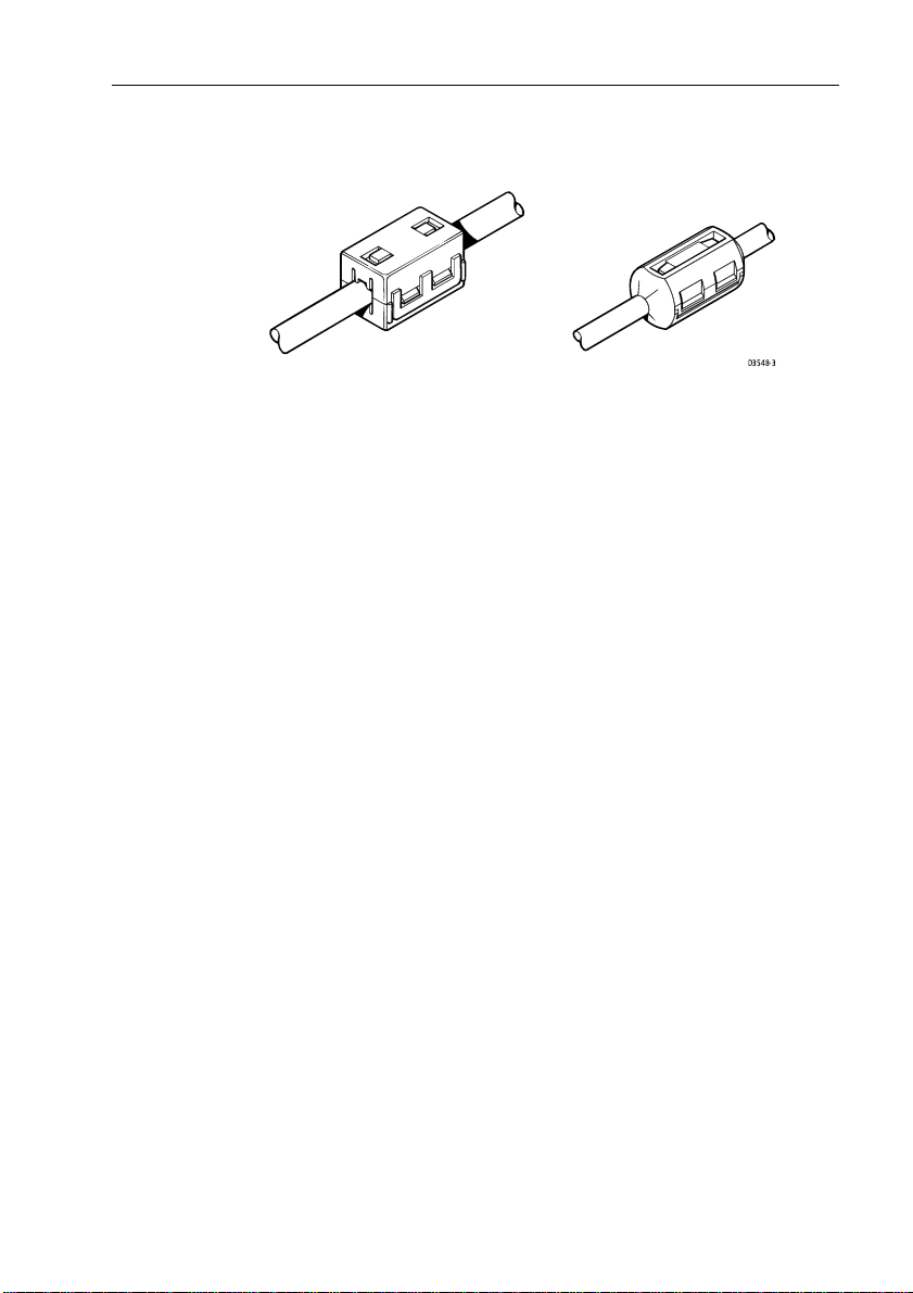
• Ifasuppressionferriteis attachedtoacable,this ferriteshouldnot
beremoved. If the ferrite needstoberemoved during installation
itmust be reassembled in thesameposition.
Page 9
Chapter 1: Overview 3
Thefollowingillustrationshows a typical range ofsuppression
ferrites fitted to Raymarine equipment.
D3548-3
Connections to Other Equipment
Ifyour Raymarine equipment is tobe connected to other equipment
usinga cablenotsuppliedbyRaymarine,asuppressionferriteMUST
always be attached tothe cable nearto the Raymarine unit.
1.2 The Fishfinder System
Transducersenablefishfinders to displaydepth, water temperature
and/orspeed, depending on thetypeof transducer(s) installed.
Beforeyou start the installation, check thatyouhave the correct
transducerfor your application, as described belowin Selecting the
CorrectTypeofTransducer.
Page 10

4 Transducers for Fishfinders
Selecting the Correct T ype of Tr ansducer
RaymarineFishfinderscan be used with anyofthe following
transducers:
T able 1-1:Transducer Types
1
Sensor
Type
Depth,
Speed, T emp
Depth,
Speed, T emp
Speed, T emp
Material
steel
Bronze Thru-Hull 600 W
Bronze Thru-Hull
Plastic Transom 600W
Part No.
E66008 Depth Plastic In-Hull 600 W
E66013 Depth Plastic Thru-Hull 600 W
E66014 Depth Bronze Thru-Hull 600 W
E66015 Depth Stainless
E66018 Speed, T emp Bronze Thru-Hull 600 W
E66019 Speed, T emp Plastic Transom 600 W
E66020
E66024 Depth, T emp Bronze T hru-Hull (high
E66029 1
E66030 Speed, T emp Plastic Thru-Hull 600 W
E66033 Depth, T emp Bronze Thru-Hull 600 W or
E66035 Depth, T emp Bronze Thru-Hull 600W
E66038 Depth,
Mounting
Method
Thru-Hull 600 W
performance)
(long stem)
Max.
Power
600 W or
1000 W
600 W
1000 W
E66043 1
1
E66020, E66029 and E66043 thru-hull transducers must be installed with a high-
speed fairing.
Depth,
Speed, T emp
Stainless
steel
Thru-Hull 600W
Note:Thisinformationwas currentasofthedatethishandbook was
printed.Newtransducer models are constantly becomingavailable.
Checkwith your dealer for themostcurrentlist.
Page 11

Chapter 1: Overview 5
WARNING:
IftheE66020,E66029 and E66043 thru-hull transducers are not
carefully installedand fitted to theshape of the hull, thevessel
maytake on water. Toensureproper alignment anda secure fit,
these transducermodels MUSTbe installed with afairing. In
additionto improving fishfinderperformance atallspeeds, the
fairingallowsbetterfittingto the hullanddramaticallyincreases
thesealing surface.
Applicatio ns
Plastichousingsare recommended for fiberglassor metalhulls.
Bronze housings arerecommendedfor wood or fiberglasshulls.
• Installa tionof a bronze housing in a metal hull requiresusing of a
fairing,available from your Raymarine dealer .
• Neverinstallametal housing in a vesselwitha positive ground
system.
Transom Mount Transducersare recommended for personal
watercraftand powerboats with outboard, inboard-outboard and jet
drives.They are NOT recommendedforlargeor twin screw inboard
boats.
• Adjuststo transomanglesfrom 3° – 16°.Forangles greater than
16
°, a tapered plastic, wood or metal shim will be needed.
• Designedfor operation from5–58 m.p.h. (4 – 50knots).
Thru-HullTransducersare recommended for boatswithstraightshaftinboard engines.
In-Hull transducers arerecommendedforfiberglasshulls,especially
inhigh speed power boatsandracingsailboats.
Planning the Installation
Beforeyou install your system, plan theinstallation,considering:
• Locationof thetransducerand fishfinder,as described in
Section 1.4
• CableRuns,includingcablesforanintegratedsystem(to provide
heading and position data,etc.), as described inSection 1.5.
Page 12

6 Transducers for Fishfinders
1.3 Unpacking and Inspecting the Components
Unpackyour system carefully,toprevent damage to theequipment.
Savethe carton and packing,in case you needtoreturn a unit for
service.
Checkthat you have allthe correct system components. These
dependon your system package, asfollows:
T able 1-2:Parts and Accessories
Part
Item
Transducer (
Transducer cable, 10 ft (3 m) extension
Transducer cable, 18 ft (5 m) extension
Transducer Y Cable
High Speed Fairing
see T able 1- 1 on page 4)
1
E66023 fairings are required for installing E66020 and E66029 bronze thru-hull
transducers.
2
E66045 fairings are required for installing E66043 stainless steel thru-hull
transducers.
No.
— — All
E66009
E66010
E66022
E66023
E66045
E66025
E66034
E26017
Supplied
with:
—
—
Speed/Temp
Transducers
1
—
2
—
—
—
—
Note:Thisinformationwas currentasofthedatethishandbook was
printed.Check with your dealer forthe most current list ofpartsand
accessories.
1.4 Selecting the Equipment Loca tion
T ransducer Mounting Location
Option
for:
All
All
All others
E66020, E66029
E66043
E66024
E66033
E66035
Itis very important thatyoumount the transducer correctly.The
transducerprovidesthe most reliable readings ifitlooksinto water
thatis smooth and undisturbed.
Page 13

Chapter 1: Overview 7
Acousticnoiseisalwayspresentandthesesoundwavescaninterfere
withthe operation of the transducer .Ambient (background) noise
fromsources such aswaves, fish, rainand other vessels cannotbe
controlled.Carefully selecting thetransducer’smounting location
can minimize noise generated by the vessel’spropeller(s), shaft(s),
machinery, andotherecho sounders. The lowerthe noise level, the
higherthe echo soundergainthat can be used,andthe better the
Fishfinder’sperformance.
CAUTION:
To ensureaccurate readings,DO NOT mount the transducerin
anareaof turbulence or bubbles:
• near waterintakeor discharge openings
• behindstrakes, fittings orhullirregularities
• behinderoding paint(an indication of turbulence)
Choosea location where:
• Thewaterflowingacrossthehullissmoothestwitha minimumof
turbulenceand bubbles (especially at highspeeds).
• Thetransducer willbecontinuously covered by waterwhen the
boatis moving. If thetransduceris mounted near the sideofthe
boat,it may be exposedwhenthe boat is turning.
• Thetransducer beamis unobstructed by the keelorpropeller
shaft.
• Thereis aminimum deadrise angle.
• Thereis adequate headroom inside the vessel for the height of the
thru-hullhousing,tighteningthenuts, and removing the valve
assembly insert.
T ransom Mount Tr ansducer
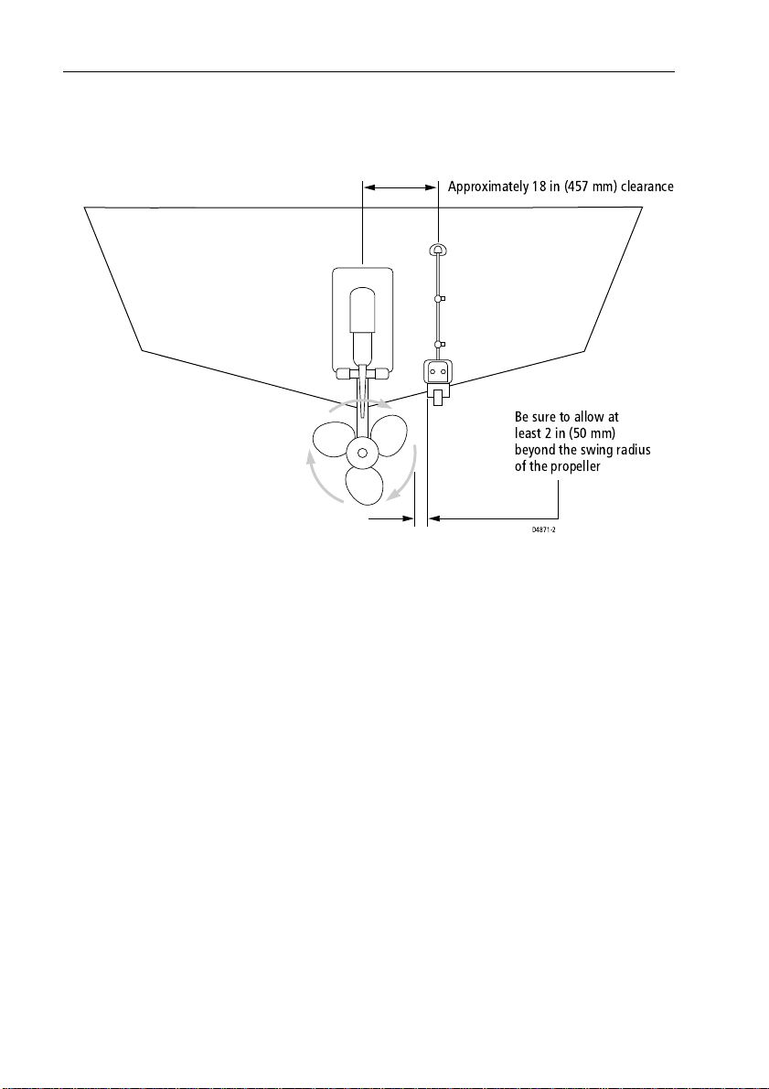
• Single drive boat -Referto Figure 1-1 . If yourboathas one pro-
peller(outboardor inboard),mountthetransducerabout 18"(455
mm)tothesideoftheboat’s centerline. To reduce anyinterfer-
encecaused by air bubbles,choosethesideon the downstroke of
thepropeller (usually the starboardside).
• Twin drive boat- If yourboathas twin propellers (outboard or
inboard-outboard),mount the transducerbetween thedrivesnear
the centerline of the boat. If the boat will be operated at high
speeds,thetransducermay be mounted closer to thecenterlineof
the hull.
Page 14
8 Transducers for Fishfinders
• Ifthe propellercanbeturnedtosteerthe boat, allow at least 2" (50
mm)beyond the swing radius ofthe propeller.Thiswillprevent
thepropeller from damagingthetransducer when itis turned.
Approximately 18 in (457 mm) clearance
Be sure to allow at
least 2 in (50 mm)
beyond the swing radius
of the propeller
D4871-2
Figure 1-1: T ransom Mount Transducer Location
• DoNotmount the transducer behind any hullfittings,intakesor
otherparts extending from the hullthatmay cause turbulence or
airbubbles.
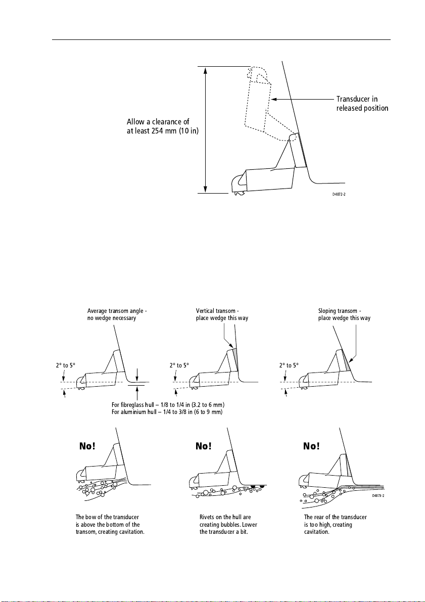
• Thebrackethas a quick-releasemechanism, shown Figure1-2 .
This allows the transducer to flip upif it hits anydebris or thebottom.Allowenoughclearanceabovethetransducerforitto swing
upwardscompletely– thisisabout10"(254mm), measured from
the bottom ofthe transom.
Page 15
Chapter 1: Overview 9
Transducer in
released position
Allow a clearance of
at least 254 mm (10 in)
D4872-2
Figure 1-2: T ransom Mount T ransducer - Quick-release Bracket
• Onaboatwithafiberglasshull, theleadingedgeofthetransducer
shouldextend1/8" (3.2 mm) to1/4"(6 mm) below the bottom
edgeofthe hull asshowninFigure1-3.Onanaluminum hull, the
transducershould extend abit more – 1/4"(6mm) to 3/8" (9 mm)
• Ifthe boat willbe trailered, besure the transducer will nothit any
rollers,bunksor fittings on the trailer.
Average transom angle -
no wedge necessary
2° to 5°
The bow of the transducer
is above the bottom of the
transom, creating cavitation.
Vertical transom -
place wedge this way
2° to 5°
For fibreglass hull 1/8 to 1/4 in (3.2 to 6 mm)
For aluminium hull 1/4 to 3/8 in (6 to 9 mm)
2° to 5°
No!No!No!
Rivets on the hull are
creating bubbles.Lower
the transducer a bit.
The rear of the transducer
is too high, creating
cavitation.
Figure 1-3: T ransom Mount T ransducer - Vertical P osition
Sloping transom -
place wedge this way
D4873-2
Page 16

10 Transducers for Fishfinders
Thru-hull T ransducer and In-hull Tr ansducer
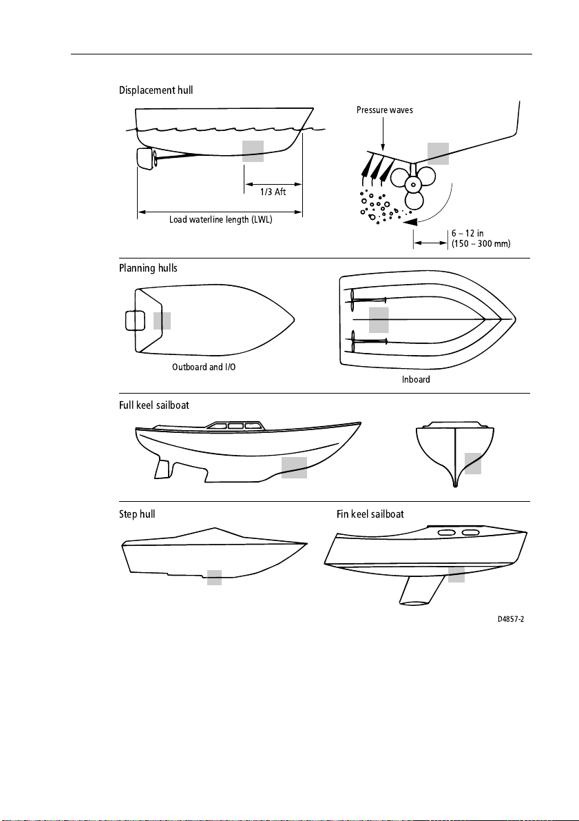
Similarconsiderationshouldbegiventothe locationof thru-hulland
in-hulltransducers.Figure1-4 shows thebesttransducerlocation for
differenthulltypes.
• Displacementhullpowerboat –Locateat 1/3 aftload waterline
length(L WL)and 6 -12" (150-300 mm) off the centerlineonthe
sideof the hull where thepropeller is moving downward.
• Planin ghull powerboat–Mountwell aft, on or nearthe center-
line, and wellinboard ofthe first set of lifting strakes to ensure
that it is in contactwiththe water at high speeds.Mounton the
sideof the hull where thepropeller is moving downward.
OutboardandI/O – Mount just forwardofthe engine(s).
Inboard–mount well forward ofthepropeller(s)andshaft(s).
Step-hull – Mount just aheadofthe first step.
Boatscapableof speeds above 25kn(29 m.p.h.) – Review
transducer location and operating results of similar boats before
proceeding.
• Finkeelsailboats– Mount to theside of the centerlineand for-
wardof the fin keel1- 2 ft (300-600mm).
• Fullkeelsailboats–Locate amidships and away from the keel at
thepoint of minimum deadrise angle.
• FiberglassHulls – Since thehullabsorbs acoustic energy,trans-
mittingthroughthe hull reduces the sensor’sperformance. Fiberglasshullsare often reinforcedinplacesforadded strength.These
coredareascontain balsa woodorstructuralfoam,which are poor
soundconductors.If you cannot avoidlocatingthesensor over
coring,followthe instructions for Installation in aCoredFiber-
glassHullon page 29.
• Thru-hullTransducer Headroom–Allowadequate headroom
insidethe vesselfortheheight ofthethru-hullhousing,tightening
thenuts and removing the insert.Theminimum headrooms are:
Withfairing:10"(254mm)
Withoutfairing: 12" (305mm)
• In-hullT ransducer–Find a location wherethe fiberglass is
solid:
Thereare no air bubblestrappedin the fiberglass resin.
Thereis no coring,flotation material,or dead airspace sandwichedbetween the inside skinandthe outer skin of thehull.
Page 17
Chapter 1: Overview 11
Displacement hull
Pressure waves
1/3 Aft
Load waterline length (LWL)
Planning hulls
Outboard and I/O
Full keel sailboat
Step hull Fin keel sailboat
Figure 1-4: Best Location for T hru Hull Transducer
Inboard
6--12in
(150 -- 300 mm)
D4857-2
Page 18

12 Transducers for Fishfinders
1.5 Cable Runs
Consider the following beforeinstalling the system cables:
• Youneed to attachthe power cableand the transducer cable.
Additionalcables will be required ifyouare installing an integrated system.
• Allcables should be adequatelysecured,protected fromphysical
damageand protected from exposuretoheat. Avoidrunning
cablesthroughbilges or doorways, or closetomoving or hot
objects.
• Acutebends mustbeavoided
• Wherea cablepassesthrough an exposed bulkheadordeckhead,
awatertightfeed-through should be used.
• Securecablesin place using tie-wraps or lacingtwine. Coil any
extra cable andtie it outof the way .
T ransducer Cable
A30 ft (10m) cableis supplied with the transducer. The transducer
cablemaybeextendeduptoamaximumof60ft(20m)using
optionalextensioncables.
Thetransducercable connector hasanutthathas been removed toaid
installation. Toallowyouto complete the installation withoutcutting
thecable, ensure that anyholesyou drill are largeenoughto accept
theconnector,withthe nut removed.
Afterthe cable has beenrunthroughthe holes, this nutmustbe
attached before the cablecan be connected,as described in
Trans ducerCable Connections onpage 39.
CAUTION:
Donot cut thetransducer cable orremovethe connector.Donot
tryto shorten orsplice the cable.If the cableis cut, itcannotbe
repaired.Cuttingthecable will alsovoidthewarranty.
• ForaTransommountinstallation–routethecable upandoverthe
top edge of the transom as shown in Figure 1-5 . Secure the cable
usingcable clamps (available fromyourlocal marine equipment
supplier).
Page 19

Chapter 1: Overview 13
Ifyou do not wantto expose the cable ondeck, you may drill a
hole13/16"(21 mm)throughthetransomforthe cable(withconnector attached). Toseal the opening, useafeed-thru cap where
thecable passes through the transom.
• Foreithertype ofinstallation –runthecablethrough the interior
oftheboat.
• Ifthe 30ft (10 m) cable isnotlong enough, extension cables are
availablefrom your Raymarine dealer.See Table 1-2 on page 6.
Total cablelength fromthetransducer tothe fishfinder must
notexceed60 ft (20 m). Whenyouattachthe extension cable, be
surethat the connections are watertight.UseDow Corning DC-4
oran equivalent sealing compound toprotectthe connector
assemblies.
Cable cover
Cable clamps
2 in (50 mm)
Figure 1-5: Installing the Cable on a Transom Mount T ransducer
D5033-2
Page 20

14 Transducers for Fishfinders
Page 21

Chapter 2: Installation 15
Chapter 2:Installation
Thischapter gives details onhowto install your transducer .
Instructionsare divided intothe following sections:
• TransomMount Transducers- recommended for personal
watercraftand powerboats with outboard, inboard-outboardand
jetdrives.
• Thru-HullTransducers -recommended for boats with straight-
shaftinboard engines.
• In-Hulltransducers- recommended for fiberglasshulls,espe-
cially in high speedpower boats andracing sailboats.
2.1 Installing the Transom Mount T ransducer
Preparation
Tr ansducer Mounting Bracket
Wheninstalled, the lower surfaceofthe transducer should tilt down
toward the rear ata slight angle (2°to 5°). The mounting bracket
includesa wedge; depending on theangleof the transom on your
boat,you may need toinstallthis wedge to getthecorrect transducer
angle.
1. T oattach thetransducer to the bracket,insert the transducer
mountinglugsinto the slot in thebracketas shown in Figure2-1 .
Correct Incorrect
Attach the two parts Bracket is installed
upside down
Lower the transducer and
snap in the release clip
Figure 2-1: Fitting the T ransducer to the Brack et
D4874-2
Page 22

16 Transducers for Fishfinders
2. Lookingatthe rear of the boat, be surethebracketis vertical (perpendiculartothewaterline) and holdthebracket(plusthe wedge,
ifused)againstthe transom.
Tracethepositionof the screw slots,then mark the screwpositionsasshown in Figure 2-2 . Theoutertwo screws should be
placed about 1/4" (6 mm) upfromthe bottom of eachslot, the
centerscrew should be placedabout 1/4" (6 mm)downfrom the
top.This will allow the brackettobe adjusted up ordown.
Remove the bracket.
Correct alignment
Insert screws 1 and 3, 6.4 mm (1/4 in)
from the bottom of the slots,and
screw 2, 6.4 mm (1/4 in) from the top
the slot to allow room for adjustment.
Incorrect alignment
If screws are inserted this way it
won't be possible to make the
height adjustment.
1
23
123
D4875-2
Figure 2-2: Position of Screws in Mounting Bracket
Installation
1. Ona fiberglass hull, to minimize surface cracking of thegelcoat:
Before drilling the pilot holes, usea 1/4" (6 mm) drill bit to drill a
shallowhole (chamfer) ateach location about 1/16"(1.5mm)
deep.
Drill pilot holes3/4" (19 mm) deep using a 9/64"(3.6 mm) drill
bit.
T opreventdrillingtoodeeply,wrapmaskingtapearoundthe drill
bitabout7/8"(22mm)fromthetip.Drillinonlyasfaras the tape.
2. Applya good quality marine sealanttothe pilot holes to protect
thehull from water penetration.
3. Attach the bracket tothe hull using the panhead screwswith flat
washers. Do notcompletely tighten thescrewsyet.
4. Movethe bracketupordown sotheleadingedgeofthetransducer
hasthe clearance showninFigure1-3.
5. Once the bracketis in thecorrect position tighten thescrews.
Page 23

Chapter 2: Installation 17
2.2 Installing the Thru-hull T ra nsducer
Tools and Material Needed
Water-based antifoulingpaint (mandatory for boatskeptinsalt
water)
Safetygoggles
Dustmask
Electric drill
Drillbit:1/8" (3 mm)
Holesaw:
Drill
Fiberglassorwood2"(51 mm)
Aluminium or steel hull 2-1/8" (54mm)
Sandpaper
File (for installation in a metal hull)
Mild household detergent or weak solvent(alcohol)
Marine sealant
Slip-joint pliers
Siliconegreaseor petroleum jelly
Tie-wraps
Coredfiberglasshull installation:
Holesaw for hull interior2-3/8" (60mm)
Cylinder,wax, tapeandcasting epoxy
Fairing(required with E66020, E66029 and E66043transducers;
optionalforE66024, E66033 and E66035
Level and protractor (installation with a fairing)
Band saw or handsaw (installation witha fairing)
Rasp(installationwitha fairing)
Preparation
Fairing
Mostvessels have a deadriseangleat the transducer’smounting
location. If thetransducer ismounted directly to the hull, thesonar
beam will be tiltedoff-vertical at the sameangle as the deadrise.To
offsetthis deadrise angle, youcan install a transducerfairing.
Differentfairings are available to fit various transducers.Fairingsare
requiredforinstallingthe E66020, E66029 and E66043 thru-hull
transducers.
Page 24

18 Transducers for Fishfinders
WARNING:
IftheE66020,E66029 and E66043 thru-hull transducers are not
carefullyinstalled andfitted tothe shape ofthe hull, the vessel
maytakeon water.Toensureproper alignment and asecurefit,
these transducer models MUST beinstalled witha fairing.In
additiontoimprovingfishfinderperformanceat all speeds, the
fairingallowsbetter fittingtothehullanddramaticallyincreases
thesealing surface.
Fairingsarealso strongly recommended for usewithother high
performancetransducers. See the table thatfollows.
Thefairing is used to:
• Verticallyorientthe sound beam bymountingthe transducer parallel to the watersurface
• Minimizeaeratedwater flowing over thetransducer’sfaceby
mountingit in deeper water
• Reducedrag bydirectingthe water around the multisensor
Thefairingis madeofhighimpact urethanewithan integratedcutting
guide.It can be shapedto accommodate a deadriseangleof up to 25°
and a range of hullthicknessesas follows:
Fairing No.
E26017 E66035
E66023 E66020
E66023 E66029
E66025 E66024
E66034 E66033
E66045 E66043
Used with
Transducer No.
Max. Hull Thickness
with Fa iring
2" (50mm)
1" (26mm)
3-3/4" (87mm)
1-3/4" (45mm)
1-3/4" (45mm)
1/2" (14mm)
Page 25

Chapter 2: Installation 19
Aft View
Backing block
minimum fairing
thickness
D5568-1
Hull
Slope of hull
Deadrise angle
Parallel to
water surface
Fairing
Isolation sleeve
Figure 2-3: Deadrise Angle and Fairing Thickness
Backing Block
Abacking block isused inside the hulltoprovide a level surface for
thehull nut to seatagainst (see Figure2-3). After cutting the fairing,
usetheremaining section with the cuttingguideasthebacking block
(see Figure 2-4 ).
⇐
BOW
Triangular recess
for anti-rotation bolt
Cutting guide
D5567-1
Figure 2-4: T ransducer Fairing E66023
Cutting the Fairi ng
1. Measure the deadrise angleofthe hull at theselected location
usinga digital level, or bubbleleveland protractor (see Figure2-
3).
2. Tilttheband saw tabletothe measured angleand secure the cutting fence (see Figur e2-5 ).
Page 26

20 Transducers for Fishfinders
Band saw table
Deadrise
angle
Bow end for
installation
on port side
D4860-2
Figure 2-5: Cutting the Fairing
CAUTION:
Thearrowonthefairingalwayspoints forwardtowardsthebow.
Besuretoorient the fairing on thebandsaw so the angle cut
matchesthe intendedside of the hull.
3. Place the fairingon the tableso the cutting guide restsagainst the
fence.The arrow/blunt end willpoint toward you for installation
on the port side andaway from you forinstallation on the starboardsideof the boat.
WARNING:
Alwayswearsafetygoggles and a dustmaskwhendrilling.
Cutting guide
Fence
4. Rechecksteps 1 through 3, thencut the fairing.
5. Shapethefairingtothehull as precisely as possible with a rasp or
powertool.
Antifouling P aint
Marinegrowth can accumulate rapidlyonthe transducer’s surface,
reducingperformancein weeks. Surfaces exposedtosalt water must
becoated with antifoulingpaint.
Page 27

Chapter 2: Installation 21
Usewater-basedantifoulingpaintonly.
Neveruse ketone-based paintsinceketones can attack many
plastics,possiblydamagingthetransducer.
Reapplypaint every sixmonths or at thebeginning of each boating
season.
It is easier to apply antifouling paint beforeinstallation, but allow
sufficientdryingtime.Asillustrated in Figure2-6 paint thefollowing
surfaces:
Exposedarea of the housing, including the acousticwindow
Boreof the housing up to1¼"(30mm)
Outside wall belowlower O-ring
Exposedendof the paddle wheelinsert
Paddlewheel cavity
Paddlewheel
Blankingplug below the lower O-ringandthe exposed end
Housing Paddlewheel
Paint exposed housing
and bore up to 1.1/4" (30 mm)
Figure 2-6: Applying Antifouling Paint
insert
Lower
'O' ring
Paint outside wall below the lower 'O' ring including
exposed end, paddlewheel cavity and paddlewheel
D4859-2
Page 28

22 Transducers for Fishfinders
Installation
Note:To install the thru-hull transducer in acored fiberglass hull,
follow the instructions in Installation in a Cored Fiberglass Hull on
page 29.
Drilling Holes
WARNING:
Alwayswearsafetygoggles and a dustmaskwhendrilling.
1. Drilla1/8"(3mm)pilot hole perpendicular tothewaterlinefrom
insidethehull(see Figure2-3 ).
Ifthere is a ribor strut near themountinglocation,drill from the
outside.
Ifthepilothole is drilled in thewronglocation, drill a secondhole
ina better location. Applymaskingtape to the outsideofthe hull
overthe incorrect hole andfill it with epoxy.
2. Cuta hole from outside the hull:
Fiberglassorwoodhull– Use a2"(51 mm) hole saw.
Aluminium orsteel hull– Use a 21/8"(54 mm) hole sawto
accommodatethe isolation sleeveused to preventcontact
between the stainless steelhousingand the metal hull.
3. Sandand clean the areaaroundthe hole, inside and outside,to
ensure that thesealant willadhere properly to thehull. If thereis
anypetroleumresidue inside thehull,removeitwitheitheramild
householddetergentora weak solvent(alcohol)before sanding.
4. Removeone safetyring,theretaining pin,thecapnut,and thehull
nutfrom the transducer (see Figure2-7 ).
Page 29

Chapter 2: Installation 23
Retaining pin
Safety ring
Cap nut
Stem
Hull nut
Backing
block
Hull
Fairing
D5566-1
Marine
sealant
Figure 2-7: Seating
Dry Fit for F airing
WARNING:
Ifa fairing is used, the anti-rotationbolt mustbeinstalled to
preventthefairingfromrotatingwhentheboatis underway.
1. Dry fit the transducer tolocate the hole for the anti-rotation bolt.
2. Threadthe transducer cable through thelargeholein the fairing
andthrough the mounting hole inthehull.Seat the transducer
firmly in therecess in the fairing.
Note:The transducer must beflushwith the fairing. If itisrecessed
morethan1/64" (0.5mm) inside the fairing,youmaycarefullyfile or
sandthefairingflush with the transducer.
WARNING:
Alwayswearsafetygogglesanda dust mask.
3. Attachthe drill bit to yourdrillappropriatefor your fairing:
Fairing Used with Tr ansducer Drill Size
E26017 E66035
E66023 E66020, E66029
E66025 E66024
E66034 E66033
E66045 E66043
3/8" (10mm)
3/8" (10mm)
1/2" (13mm)
1/2" (13mm)
3/8" (10mm)
Page 30

24 Transducers for Fishfinders
4. Slidethetransducer’sstem with the fairing inplace into the
mountinghole.Besurethe triangularrecessinthefairingis pointing forward toward the bow.
5. Whileholding the assembly in placeandusingtheboltholeinthe
fairingasyourguide,drill a hole through the hull for theanti-rotation bolt.
6. Removethe assembly and cable from themountinghole.
7. Sandand clean the areaaroundthe hole, inside and outside,to
ensure that thesealant willadhere properly to thehull.
Metalhull-Remove any burrsaroundboth holes with a fileand
sandpaper .
BOW
Anti-rotation
bolt
⇐
Nut and
washer
Triangular plug
with curved surface
facing outward
Backing
block
D5565-1
Fairing
Figure 2-8: Using a Fairing and Backing Block
Seating
1. Remove the transducer from the fairing, if used.
2. Stainlesssteeltransducer in metalhull - Slidethe appropriate
sizeisolation sleeveover the cableandonto the stemof the transduceras far down aspossible(see Figure2-3 ). Be sure thetopof
theisolation sleeve will be belowthe top of the backingblockto
preventthe sleeving from interfering withtighteningthehull nut.
WARNING:
To prevent electrolyticcorrosion,neverallow direct contact
betweena stainlesssteel transducerand a metal hull.
Page 31

Chapter 2: Installation 25
3. Applya 1/16" (2mm) thick layerofmarine sealant to thesidesof
thetransducerthatwillcontactthefairing, ifused,andup thestem
1/4"(6mm) higher than thecombined thickness of the fairing,
hull,backing block, andhullnut. This will ensurethere is marine
sealantinthethreads to seal the hullandholdthehullnut securely
in place (see Figure2-7 ).
Stainlesssteel transducerinmetalhull - Apply the marine sealantto the outside of thesleevinginsteadof the stem itself.
4. Ifafairing is used, thread thetransducercable through the fairing
andseat the transducerfirmly within the recessin the fairing.
5. Applya 1/16" (2mm) thick layerof marine sealant to thesurface
ofthe fairing thatwill contact thehull, if used.
Attaching the Transducer
1. Fromoutside thehull,threadthecable throughthemountinghole.
2. Push the stem ofthe transducer(with thefairing in place)into the
mountingholeusinga twisting motiontosqueezeoutexcesssealant.
3. Frominsidethe hull, slide the backingblockonto the transducer
cable and stem, seating itfirmly against the hull (Figure2-9 ).
CAUTION:
Be careful toavoid cross threading the cap nut.
4. Screwthe hull nut in placeandtightenit with slip-joint pliers.
Stainlesssteeltransducer in metalhull - Be sure the top of the
isolation sleeve is belowthe top of thebacking block to prevent
thesleeving from interfering with tighteningthehull nut.
5. Applya 1/16" (2mm) thick layerofmarine sealant to theantirotationbolt,1/4" (6mm) higher than thecombinedthicknessof
thefairing, hull, backing block, washer,and nut. Thiswillensure
thatthere is marine sealant on thethreads to seal thehull and hold
thenut securely inplace (see Figure 2-8 ).
6. Pushthebolt through the fairing, if used,andintothe hull.
7. Frominside the hull,slidethewasher and nutontothebolt.Screw
the nut in place and tighten it withslip-joint pliers.
Wood hull - Allow for thewood to swell.
Page 32

26 Transducers for Fishfinders
Cable
Safety chain
Pull ring
Safety ring
Cap nut
Stem
Backing block
D4863-2
Figure 2-9: Fore View of Transducer Installation
8. Ifa fairing is used,apply marine sealantto the flat sideofthetri-
angularplug. Push the plugintothe triangular recess in thefairing.Thetriangularplugfitsonewayonly.Besurethecurved
sideof the plug is exposed,matchingthecurve on the outsideof
thefairing. Tapit into place with a mallet.
CAUTION:
Forsmoothwater flow over thetransducer’ssensor,besurethat
theexternalsurfaceof the installedtriangularplugisFLUSH
withthe external curvedsurfaceof the fairing.
9. Beingsurethe valve assembly is seatedfirmlyinthe housing,
carefullyscrew the capnut in place.Hand tighten itonly; do not
over tighten.
10. Remove any excesssealanton the outside of thehullto ensure
smoothwater flow over thetransducer .
Retaining pin
Safety wire
Hull nut
Hull
Fairing
Transducer
Page 33

Chapter 2: Installation 27
11. After thesealant cures, inspect andlubricate the O-rings onthe
paddlewheel insert with silicone greaseorpetroleum jelly (see
Figure2-10 ).
12. Slide the paddle wheelinsert into the valve assembly with the
arrowonthetop pointing forward untilitisfullyseated(the insert
fitsone way only).
Take care nottorotate the outer housinganddisturbthe sealant.
13. Slide the centerring of the safetychainonto the cable. Slidethe
retaining pin inplace and reattach thesafety ring (Figure2-9 ).
WARNING:
Alwaysattach the safety wiretopreventthe insert from backing
outin the unlikelyevent that thecap nut failsor is screwedon
incorrectly.
14. Wrapone end of thesafety wire tightly around thestemof the
housingandtwist it together withthelong end. Lead thewire
straightup and throughoneeyeinthecapnut,then throughoneof
thesafety rings. Loop the wire throughthepullring and twist it
securely to itself.
15. Route the cabletothe transducer,being careful not totearthe
cablejacket when passing itthroughthebulkhead(s) and other
partsof the boat.
16. Attach the connectornutto the cable per instructionsinTrans-
ducerCable Connections on page 39.
17. Attach theassembledconnector cable tothetransducer.
18. Routetheotherend ofthecabletothefishfinder,being careful not
to tear the cablejacket when passingit through the bulkhead(s)
andother parts of theboat.Toreduce electricalinterference, separatethe transducer cablefromother electrical wiringand the
engine.
19. Coil any excess cable and secure it in placeusingtie-wrapstoprevent damage.
Page 34

28 Transducers for Fishfinders
Top view of
paddlewheel
insert
Paddlewheel
insert
BOW
Paddlewheel detail
Notches
Pull ring
Flat side of
paddlewheel
blade faces bow
'O' rings
Housing
and valve
assembly
Cable
Key (2)
Valve assembly
Cap nut
Housing
D4864-2
Figure 2-10: Servicing the Paddle Wheel Insert and Valve Assembly
Page 35

Chapter 2: Installation 29
Installation in a Cored Fiberglass Hull
Thecore (wood or foam)mustbe cut andsealedcarefully.Thecore
mustbeprotectedfromwaterseepageand the hull mustbereinforced
topreventitfromcrushing under thehullnut,allowingthe housing to
becomeloose.
WARNING:
Alwayswearsafetygogglesand a dustmaskwhendrilling.
1. Drill a 1/8" (3mm) pilot hole perpendicular to thewaterline from
inside the hull.If there is a ribor strutnear the selected mounting
location,drill from the outside (seeFigure2-10).If the hole is
drilledinthe wrong location, drill asecondhole in a betterlocation.Applymaskingtape to the outsideofthehullover the incorrecthole and fill itwithepoxy.
2. Usinga 2" (51 mm) holesaw,cut a holefrom outsidethe hull
through the outerskinonly.
3. Usingthe 2 3/8"(60mm)holesaw,cut throughtheinnerskinand
mostof the core from insidethehull.The core material can be
verysoft.Apply only light pressure to thehole saw after cutting
throughthe inner skin toavoid accidentally cuttingthe outer skin
Note:The optimal interior hole diameterisaffected by the hull’s
thicknessand deadrise angle. It must be largeenoughin diameter to
allow the coreto be completely sealed.
4. Removethe plug of core materialsotheinside of the outer skin
andinner core of the hullis fully exposed. Clean and/or sandthe
innerskin,core, and the outerskinaround the hole.
CAUTION:
Completelysealthehull to prevent water seepage intothecore.
5. Coat a hollow orsolid cylinder of the correct diameter with wax
andtapeitinplace.Fillthegapbetweenthecylinderandhull with
castingepoxy.After theepoxy has set, removethecylinder (see
Figure2-11).
Page 36

30 Transducers for Fishfinders
Dimension equal to the thickness of the hull's
outer skin to ensure adequate clearance
Casting epoxy
Hull
Figure 2-11: Preparing a Cored Fiberglass Hull
6. Sandand clean the areaaroundthe hole, inside and outside,to
ensure that thesealant willadhere properly to thehull. If thereis
anypetroleum residue inside the hull,removeit with either mild
householddetergentora weak solvent(alcohol)before sanding.
7. Proceedwith Seating on page 24 and AttachingtheTransducer
onpage 25.
Check for Leaks
WARNING:
Never installa thru-hull transducer andleave theboat
unchecked for severaldays.
1. When the boatis placed inthe water, immediatelycheck around
thethru-hull transducer for leaks.Note that verysmall leaks may
notbe readily observed. Do not to leavethe boat inthe water for
morethan3 hours before checkingitagain.Ifthere is asmallleak,
theremay be considerablebilgewater accumulationafter 24
hours(probablynot enough to causewaterdamage). If a leakis
observed,repeat Seating on page 24 and Attachingthe Trans-
ducer on page 25 immediately.
D4865-2
Inner skin
Core
Outer skin
Solid or
hollow
cylinder
Page 37

Chapter 2: Installation 31
2.3 Installing the In-hull T ra nsducer
Tools and Material Needed
Tape
Pole
Detergent
Weak solvent (alcohol)
Safetygoggles
Dust mask
Disc sander
Thin, sealable plastic bag (optional)
T wist-tie
Petroleum jelly (Vaseline®)
Leveland protractor
Carpenter’ssquare
Pencil
Adhesive(Loctite#5699 or 3M #4200)
Screwdriver
Siliconegrease (optional)
Mineraloil 2.4 fl oz.(71mil)
Cored fiberglass hull installation:
Drill
Holesaw for hull interior4"(100 mm)
Miniaturedisk sander
Castingepoxy(polyproxy#7035/7040)or resin
Papercup
Stirrer
Testing the Selected Mounting Location
Establishing a Performance Baseline
The results of thistest are used todetermine the bestin-hulllocation
fora transducer.
1. Take the boat to the maximum depth for which yourinstrumentis
rated,or the maximum depth inwhichyou will operate thefishfinder.
2. Connectthe transducer to thefishfinder.Refer to Transducer
CableConnections on page 39.
Page 38

32 Transducers for Fishfinders
3. Tape the transducertoa pole with thecable side up. Hold itover
theside of the boatwiththe active face submergedinthewater
(seeFigure2-12). Keep the activeface of the transducerparallel
to the surface ofthe water.
4. Observethe Fishfinder’sperformance and depth reading.
D5000-2
Figure 2-12: Establishing a Performance Baseline
Testi ng the Mounting Loc ation
Whiletheboat is moving aroundthesame site (and depth ofwater),
testthe transducer at your selectedmountinglocation inside the hull.
Useone of the methodsbelow:
1. Thismethodisrecommendedifthesensorwillbelocatednearthe
stern and the boat hasa minimum deadrise angle.
i. Clean away any largebuild-upof dirt and/or greaseusing
detergentor a weak solventsuch as alcohol.
ii. Placethe sensor against the hull andallowbilgewatertocover
thesurface where theytouch (see Figure 2-13 A).
WARNING:
Alwayswearsafetygoggles and a dustmask.
2. Thismethod can be usedat all hull locations.
i. Ifthe hull surface is notsmooth,grind it with a discsander.
ii. Partiallyfill a thinplastic bag with water, place the sensor
inside the bagand close it tightly with atwist-tie.
iii. Wetthesurface of the hull and pressthesensor face againstit
throughthe bag (see Figure 2-13 B).
Page 39

Chapter 2: Installation 33
WARNING:
Alwayswearsafetygogglesanda dust mask.
3. Thisis the leastdesirable testing method,as it may be difficult to
removealltracesof the petroleumjellybeforebondingthebaseto
the hull.
i. Ifthe hull surface is notsmooth,grindit with a discsander.
ii. Coatthe face of the sensor with petroleum jelly.
iii. Press it against the hull with a twisting motion (see Figure2-
13C).
ABC
D5001-2
Figure 2-13: T esting the Transducer at the Selected Location
Observe the Fishfinder’sperformance and compare it to the baseline.
Lookfor astabledepthreadingthat issimilartothebaseline,compare
thethickness and intensity ofthe bottom trace.
Ifthe performance is closeto the baseline, thisisa good mounting
location.Remember,someenergyis lost transmitting through the
hull.
Ifthetestreadingdiffersmarkedlyfromthebaseline,youneedtofind
anotherlocation to install the transducer.
Ifthereis no reading oritiserratic, the sensormaybepositioned over
coringwhich is absorbing the acoustic energy. Choose another
location.If no other spotisavailable, check with theboat
manufacturer to becertain coring is presentbefore proceeding
with Installationin a Cored FiberglassHullon page 37.
Page 40

34 Transducers for Fishfinders
Installation
1. Measurethe deadrise angle of thehullat the selected location
usingalevelandprotractor (see Figure2-14). Measurecarefully ,
sincethe installed transducer must be within5° of vertical.
WARNING:
Alwayswear safetygogglesand a dustmask.
2. Thehullsurfacetobebondedmustbesmoothand free of paint or
anyother finish. If the surfaceisrough, use a discsanderto
smoothan area 4" (100 mm) indiameter.
3. Remove any dust, grease oroil with a weak solvent, such asalcohol,to ensure a good bond.Cleanand dry both theselectedarea
andthe underside of the base.
4. Usinga carpenter’ssquare, draw alineon the hull perpendicular
tothe keel through thecenter of the mounting location.Thiswill
beused as a guidelineto orient the base.
Hull
Flange
Deadrise angle
D5002-2
Guideline
perpendicular
to keel
Parallel to waterline
Base
Figure 2-14: Deadrise Angle
5. Thenumbers on the flange ofthebase represent deadrise angles.
Identifythenumberthatmostcloselycorrespondstothedeadrise
angleof your hull. Find itsmatchon the opposite side of the
flange.Keeping the keel directionarrowson the side ofthebase
nearest the keel, alignthetwo raised marksindicating your
deadriseanglewiththe guideline drawn on the hull (see Figure2-
15).
Page 41

Chapter 2: Installation 35
CAUTION:
Thebasemustbeliquid-tight.
6. When you are satisfiedthat the locationofthe transducer isoptimaland the orientation of thebase corresponds to the deadrise
angleof your boat, apply abead of adhesive to thebottomof the
baseflange.(Followtheadhesive manufacturer’sinstructionsfor
use).
Pressthe flange firmly in placeto form a liquid-tight seal and
allow the adhesive to cure.
Keel
Keel direction arrow
Keel direction arrow
D5003-2
Figure 2-15: Aligning the Base Flange with 4–12° Deadrise Angle
7. Slidethetransducer housing into the locking ring.T urnthe housinguntil the rib thatmost closely corresponds to thedeadrise
angleof your hull is alignedwiththeangle indicator on thelockingring.Tosecure thehousingto the locking ring, inserttwo
screws(see Figure2-16 ). Do notovertighten the screws.
Page 42

36 Transducers for Fishfinders
Transducer
housing
Locking
ring
10° deadrise
angle shown
Angle
indicator
Ribs
D5004-2
Figure 2-16: Joining the Transducer Housin g to the Locking Ring
8. LubricatetheO-ring withsiliconegreaseor petroleum jelly.Slide
theO-ring onto the transducerassembly(see Figure2-17 ).
Transducer
housing
Locking
ring
Front view Side view
'O' ring
D5005-2
Figure 2-17: Installing the O-ring
9. Whentheadhesive on the base has cured,pour2.4fl. oz. (71 mil)
of mineral oilinto the base.
10. Lock the transducerassemblyintothe base by insertingthekeys
onthe locking ring in thenotches in the base. Pressdownand
rotate clockwise until seated(see Figure2-16 ).
11. Route thecable to the transducer,being carefulnotto tear the
cablejacket when passing it throughthebulkhead(s) and other
partsof the boat.
Page 43

Chapter 2: Installation 37
12. Attach the connectornutto the cable per instructionsinTransducerCable Connections on page 39.
13. Attach theassembledconnector cable tothetransducer.
14. Routetheotherend ofthecabletothefishfinder,being careful not
to tear the cablejacket when passingit through the bulkhead(s)
andother parts of theboat.Toreduce electricalinterference, separatethe transducer cablefromother electrical wiringand the
engine.
15. Coil any excess cable and secure it in placeusingtie-wrapstoprevent damage.
Note:Ifyouareusing an extension cable, besuretolocatethemated
3-pinconnectors wellabovethebilge waterline.Tofacilitatethis, use
cableclamps on either side oftheconnection.
Installation in a Cored Fiberglass Hull
Installationina cored hull is difficult.The objectiveis to bond the
sensortotheinsidesurfaceofthehull’souterskin whilepreventing
anymoisture from penetratingthe core.
CAUTION:
Thereisnowayto determine iftheouterskinis solid (no trapped
airbubbles inthe fiberglass)at the selected location before
cuttingthe inner skin.
WARNING:
Alwayswearsafetygogglesanda dust mask.
1. Usinga4"(100 mm)hole saw,cutthroughtheinner skin and the
coreat the selected location (see Figure2-18).Thecorematerial
canbe very soft. Applyonlylightpressure to the holesawafter
cuttingthroughthe inner skin toavoid accidentally cutting the
outer hull.
2. Removethe plug of core material,sotheinner core of the hullis
fullyexposed.Sand the inside surfaceof the outer skin using a
miniaturediscsander.Slightlyundercutthe surrounding coringif
possible.
3. Cleanand dry both theinside surface of theouter skin and the
housingwithaweaksolvent,suchasalcohol,toremoveanydust,
greaseoroil.
Page 44

38 Transducers for Fishfinders
CAUTION:
Donotproceedif thehulltemperatureisbelow60°F(15°C)since
thecuretimeofthecastingepoxywillbegreatlyextended.
4. Ifthe hull temperature is above60°F(15°C),mix a half cupof
castingepoxystirringcarefully to avoid trappingairinthe mixture.
Pourthis around the housing until the cavityisfull.Allow the
castingepoxyto set foratleast1 hour.
100 mm(4 in)
Transducer assembly
Hull thickness
Inner skin
Core
Outer skin
Fill with casting epoxy
D5006-2
Figure 2-18: Installation in a Cored Fiberglass Hull
5. Proceed with step7 of Installa tion on page 34.
Page 45

Chapter 2: Installation 39
2.4 Tr ansducer Cable Connections
Thetransducer cable connector (andY-connector,if supplied) has a
nutthat has been removedto aid installation. To allow youto
completethe installation withoutcutting the cable, ensurethat any
holesyou drill are largeenoughto accept the connector,with the nut
removed(approximately13/16" or 21mm).
Beforeattaching the transducer cable, you willneed to attach the
connectornutand split ring. These items,plusa wedge tool, are
included in the transducer packaging.
Connector/cable
Protrusion
Mounting groove
Nut
Split
Split ring
Wedge tool
Figure 2-19: Assembling the T ransducer Connector
CAUTION:
Takecarenottopullonthecable–this can damage the
transducer wires.
D5256-1
Page 46

40 Transducers for Fishfinders
➤ Toattach thetransducer cable connector:
1. Slipthe nut over the connectorcableend. Push it pasttheconnectorand over thecable.
2. Insertthewedge tool into thegrooveinthe split of the splitring
andslide the wedge tool untilitssquared end is flush with the
largeredge of the split ring.
3. Slipthe split ring and wedgetool over the connector bodyuntil
alignedwith the mounting groove ontheconnector.
4. Removethe wedge tool and seatthesplit ring in themounting
groove,making sure the connector protrusionfallsintothe split.
5. Slipthenut forward until it stops.Twist until the protrusions on
theinside of the nut alignwiththe grooves on the splitring.
6. Slipthe nut forward andsnapinto place.
Thetransducer cable isattached to the 7pin male connectormarked
TRANSDUCERonthefishfinder.How you connect thecableto theunit
dependson the type of transduceryou have installed:
• Combined depth/speed/temptransducershave a 7 pinfemale
connector.Attach the transducer cable connectordirectly to the
fishfinder.
• Combinedspeed/temperature transducers havea 3 pinfemale
connectorthat requires the use ofan additional Y -shapedcable
(RaymarinepartnumberE66022)toattachtothe 7 pin connector
on the fishfinder.ThisY-cable is included withyour speed/temperaturetransducer.
Attachthe7 pin female connector on the Y-cableto the fishfinder
unitthen attach the transducercable to the 3pinmale connector
on the Y-cable.
• Depth-onlytransducers have a 7pinfemale connector.
Attach the transducercable connector directlyto the fishfinder.
or
• Ifbeing installedinconjunction with a speed/temperaturetransducer,attach the 7pinfemaleconnectorontheY-cableto the fishfinderthenattachthetransducercabletothe7pinmaleconnector
on the Y-cable.
Note:If your system requires both a Y-cable and a transducer exten-
sioncable, ensure that you connecttheY-cable to the fishfinder and
theextension cable to thetransducer.
Page 47

Chapter 2: Installation 41
CAUTION:
Donot cut thetransducer cable orremovethe connector.Donot
tryto shorten orsplice the cable.Ifthe cable iscut, it cannotbe
repaired.Cuttingthe cable will alsovoidthe warranty.
Page 48

42 Transducers for Fishfinders
Page 49

Chapter 3: Maintenance 43
Chapter 3:Maintenance
Cleaning Instructions
Cleaning the Transducer
Seagrowth can collect quicklyonthe bottom of the transducer,this
canreducethe performance in justa few weeks. Topreventthebuildupof sea growth, coatthetransducer with a thinlayerof paint. Use
onlya water-based antifouling paint, orawater-basedpaint
specificallydesigned for transducers. Apply thepaint with a brush.
Ifyour transducer becomes fouled orstopsworking because of sand
orsea growth, use a stiffbrushtoclean it. Youmay sandthe surface
witha fine-grit wet ordry sandpaper (#320 grade orfiner),but this
will affect the performance ofthe unit when theboat is moving at
higherspeeds.
Thepaddle wheel mechanismmaybecome jammed bydirt,grit or
barnacles. Workthis out ofthe mechanism, then clean the unit with
soapand water oralcohol.
Cleaning the Hull
Usecautionwhen sanding or cleaning theoutsideofthehull near the
transducer.
CAUTION:
Harshcleaningsolventssuch as acetone maydamagethe
transducer.
Servicing and Safety
• Raymarineequipment shouldbe serviced only by authorized
Raymarineservice technicians. They will ensurethatservice proceduresand replacement partsusedwill not affect performance.
Thereare no user serviceableparts in any Raymarineproduct.
• Someproducts generate high voltages, so neverhandlethe
cables/connectorswhen power is beingsuppliedtothe equipment.
• Whenpowered,all electrical equipmentproduceselectromagnetic fields. These cancause adjacent pieces of electrical equipmentto interact with oneanother,with aconsequentadverse
effecton operation.
Page 50

44 Transducers for Fishfinders
• Inordertominimize these effects and enableyouto get the best
possibleperformancefrom your Raymarine equipment, guidelinesare given in the installationinstructions,toenableyouto
ensureminimum interaction betweendifferentitems of equipment, i.e., ensureoptimum Electromagnetic Compatibility
(EMC).
• Alwaysreport anyEMC-relatedproblemto your nearest Raymarinedealer.We use suchinformation to improve ourquality standards.
• Insome installations,it maynotbe possible to prevent theequipmentfrom being affectedbyexternal influences. In generalthis
willnotdamagetheequipmentbutitcanlead tospuriousresetting
action, or momentarily may result in faulty operation.
Problem Solving
Common Problems and Their Solutions
T able 3-1:Common T ransducer Problems
Problem Correction
Fishfinder display
“freezes”
Fishfind er does
not see bottom or
fish
Fishfind er does
not display fish
Fishfinder is unreliable at high boat
speeds
Fishfinder displays
a lot of background noi se
Fishfind er speed
or log readings are
wrong
Check the transducer cable for damage. If damaged, the c able and t ransduce r must be re placed
as a unit.
1. If you have a transom-mount transducer , check
that the transducer hasn’t kicked-up on hitting an
object.
2. Check that the transducer is within 10° of vertical.
3. Check that the transducer face is not covered or
fouled. If necessary clean the transducer .
Ensure the t ransducer is within 10 ° of vertical.
Turbulence around the transducer may be confusing the unit.
Check that the transducer is mounted correctly
and is clean.
Check that the transducer paddle wheel is clean.
Page 51

Chapter 3: Maintenance 45
How to Contact Raymarine
On the Intern et
Vi si tthe RaymarineWorld WideW ebsite forthelatestinformation
onRaymarine electronic equipment and systemsat:
www .r aymarine.com
Customer Support
Navigate to theCustomer Support page for links to:
• FindingFactoryService locations andAuthorized Dealers near
you
• Registeringyour Raymarineproducts
• Accessinghandbooks in AdobeAcrobatformat
• DownloadingRayTech software updates
• Accessingthe Raymarinesolutiondatabase
ClickingtheFind Answers linkroutesyou to our solutiondatabase.
Searchquestionsand answers by product,category, keywords,or
phrases.If the answer you areseeking is not available,clickthe Ask
Raymarinetab to submit yourownquestiontoourtechnicalsupport
staff, who reply to youby e-mail.
In the US
Accessories and Parts
Many Raymarine accessory itemsand parts canbe obtained directly
fromyourauthorized Raymarine dealer. However, if you arein need
ofan item notavailablefrom the retailer,pleasecontact Raymarine
T echnicalServicesat:
800-539-5539ext.2333,or
603-881-5200.
T echni calService isavailableMondaythrough Friday 4:00 AM to
6:00 PM Eastern Time.
PleasehavetheRaymarineitemorpartnumberreadywhencallingif
placinganorder.Ifyou arenotsurewhich item isappropriateforyour
unit, you should firstcontact the TechnicalSupport Department to
verifyyour requirements.
Page 52

46 Transducers for Fishfinders
Technical Suppo rt
For technical support,call:
800-539-5539ext.2444,or
603-881-5200.
OurTechnicalSupport Specialistsareavailable to answer questions
aboutinstalling,operating and trouble-shooting all Raymarine
products.
Questionscan be sent directly toourTechnicalSupport Department
viatheInternet.Point your browsertowww.raymari ne.comandclick
onthe Customer Support link. Fromthere, select Find Answers
and click the Ask Raymarine tab.
Product Repair and Service
IntheunlikelyeventyourRaymarineunitshoulddevelopaproblem,
please contact your authorizedRaymarine dealer for assistance.The
dealeris best equipped tohandleyour service requirements andcan
offertimesaving help in gettingthe equipment back intonormal
operation.
In the event that repairscan not be obtained conveniently, product
servicemay also be obtained by returningtheunitto:
Raymarine, Inc.
ProductRepair Center
22CottonRoad, Unit D
Nashua,NH03063-4219
TheProductRepairCenterisopenMondaythroughFriday8:15a.m.
to5:00 p.m. Eastern Time.Allproductsreturned to the Repair Center
areregistered upon receipt. Aconfirmationletter will be sentto you
acknowledgingtherepair status and theproduct’s referencenumber.
Shouldyouwishtoinquireaboutthe repairstatusofyourunit,contact
theProduct Repair Center at:
800-539-5539
Please have the product referencenumber,orunitserial number,
readywhen you call. We will doeverythingpossibleto make the
repairand return your unitasquickly as possible.
Page 53

Chapter 3: Maintenance 47
In Europe
InEurope, Raymarine support, service and accessoriesmay be
obtainedfrom your authorized dealer,or contact:
Raymarine Ltd
AnchoragePark
Portsmouth,Hampshire
EnglandPO3 5TD
Tel +44 (0)239269 3611
Fax+44 (0) 23 9269 4642
Technical Support
TheTechnicalServices Departmenthandlesinquiries concerning
installation,operation,faultdiagnosisand repair.Fortechnical
helpdesk contact:
Tel:+44 (0) 2392714713
Fax:+44(0) 23 9266 1228
Questionscan be sent directlytoour TechnicalSupportDepartment
viatheInternet.Point your browsertowww .raym ar ine.comand click
on the CustomerSupport link. From there,select FindAnswers
andclick the AskRaymarinetab.
Accessories and Parts
Raymarineaccessory items andparts are available throughyour
authorized Raymarine dealer .Please referto the lists of component
partnumbers and optional accessoriesin the Installation chapterof
thismanual, and have theRaymarine part number readywhen
speaking with your dealer.
Ifyou are uncertain aboutwhat item to chooseforyourRaymarine
unit, please contact ourCustomer Services Department prior to
placingyour order.
Worldwide Support
Pleasecontact the authorized distributor in thecountry.A listof
worldwidedistributorsissuppliedwith your system.
Page 54

48 Transducers for Fishfinders
Page 55

Index 49
Index
A
Accessories 6
B
Backing Block 19
C
Cable Runs 12
Installation Considerations 5
Cleaning Instructions 43
Connections
Transducer 39
Cored Fiberglass Hull - Transducer Installation 29, 37
E
EMC iv
Conformance iv
Installation Guidelines 2
F
Fairing 6, 17
H
Help from Raymarine 45
I
In-hull Transducer 1
Installation 31
Cored Fiberglass hull 37
Location 10
Installation
Cable Runs 5, 12
EMC Guidelines 6
In-hull Transducer 31
Location 5
Thru-hull Transducer 17
Transom Mount Transducer 15
L
Location
In-hull Transducer 10
Transducer 6
M
Maintenance 43
P
Problem Solving 44
S
Safety
and Servicing 43
EMC Guidelines 6
Servicing 43
T
Thru-hull Transducer 1
Installation 17
Location 10
Transducer
Applications 5
Cable 12
Connections 39
In-hull 1
Installation 15, 17, 31
Cored Fiberglass Hull 29, 37
Location 6
Thru-hull 1
Transom Mount 1, 7
Transducer Types 4
Transom Mount Transducer 1, 7
Installation 15
Cored Fiberglass hull 29
W
Warranty iv
Page 56

50 Transducers for Fishfinders
 Loading...