

Page 1

Tiller Drive
Installation Guide
Document numbe r: 870 612
Date: Oct 2006
Page 2

Page 3
Tiller Drive 3
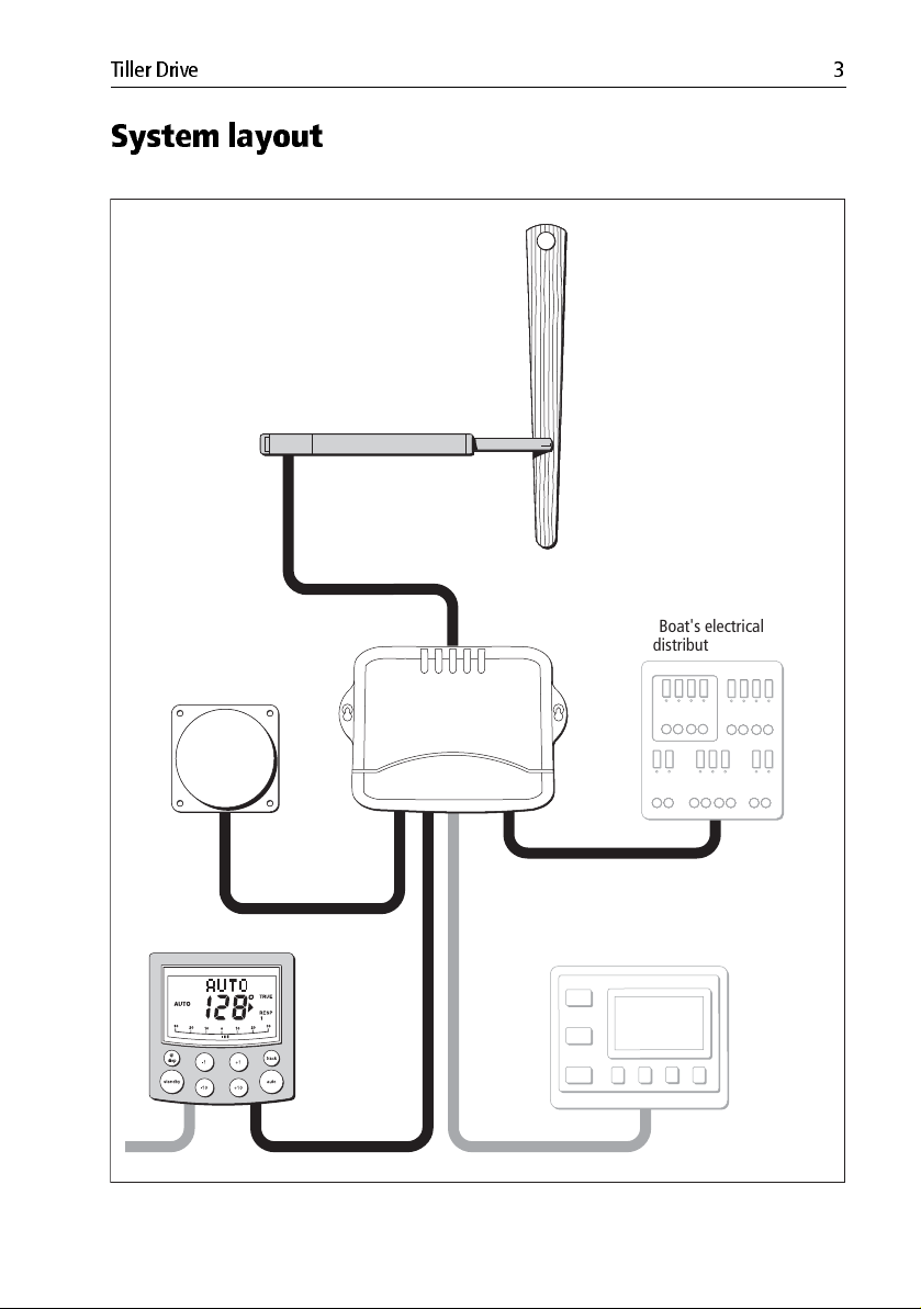
System layout
Tiller drive
Fluxgate compass
Control unit
Course computer
Boat's electrical
distribution panel
NMEA
instrument
or navigator
D8922-1
Page 4
4 Tiller Drive
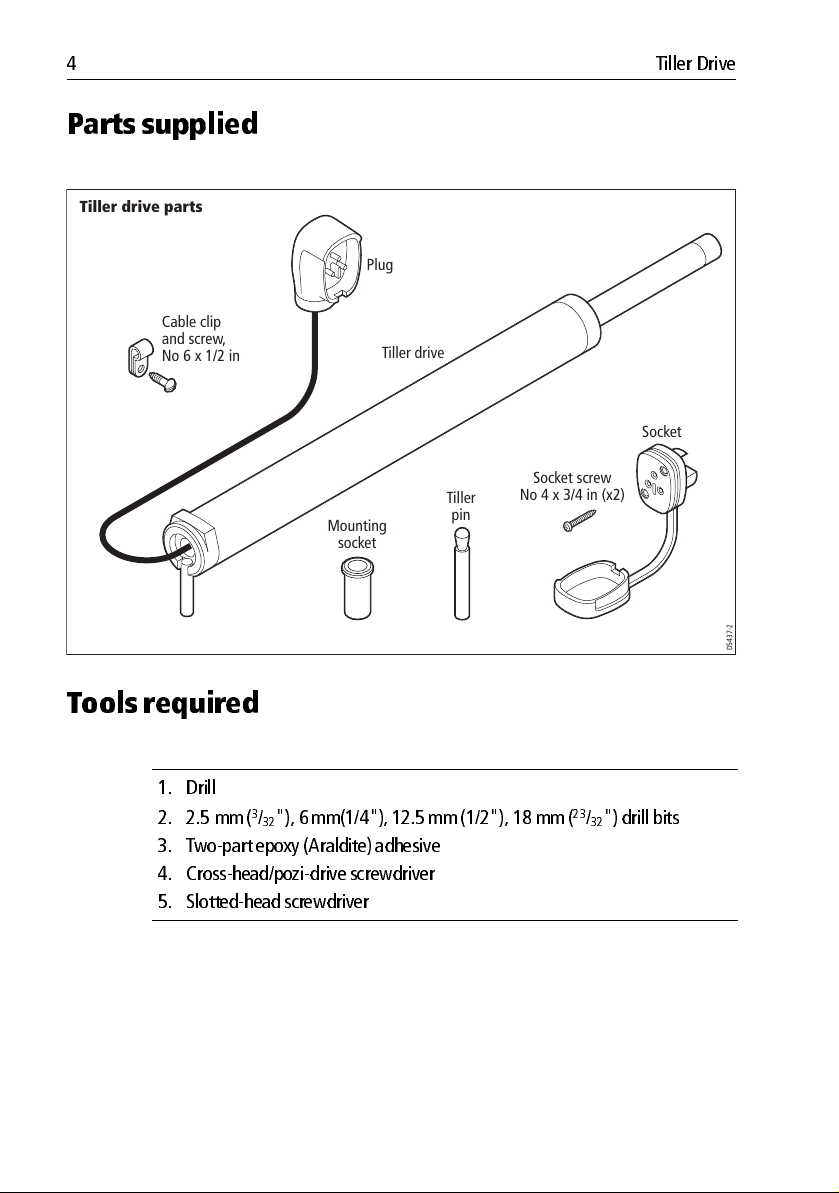
Parts supplied
Tiller drive parts
Plug
Cable clip
and screw,
No 6 x 1/2 in
Mounting
socket
Tiller drive
Tiller
pin
Socket
Socket screw
No 4 x 3/4 in (x2)
To ols requir ed
1. Drill
2. 2.5 mm (
3. Two part epoxy (Araldite) adh esive
4. Crosshead/po zidrive screwdriver
5. Slottedhead sc rewdriver
3
/32"), 6 mm(1/4"), 12.5 mm (1/2"), 18 mm (23/32") drill bits
D5437-2
Page 5
Tiller Drive 5
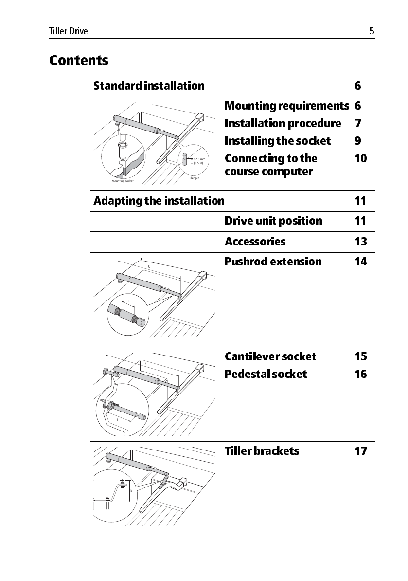
Contents
Standard installation 6
Mounting socket
Tiller pin
12.5 mm
(0.5 in)
Mounting requirements
Installation procedure
Installing the socket
Connecting to the
course computer
6
7
9
10
Adapting the installation 11
Drive unit position 11
Accessories 13
C
L
F
Pushrod extension 14
Cantilever socket
Pedestal socket
15
16
L
Tiller brackets 17
E
Page 6
6 Tiller Drive
Standard installation
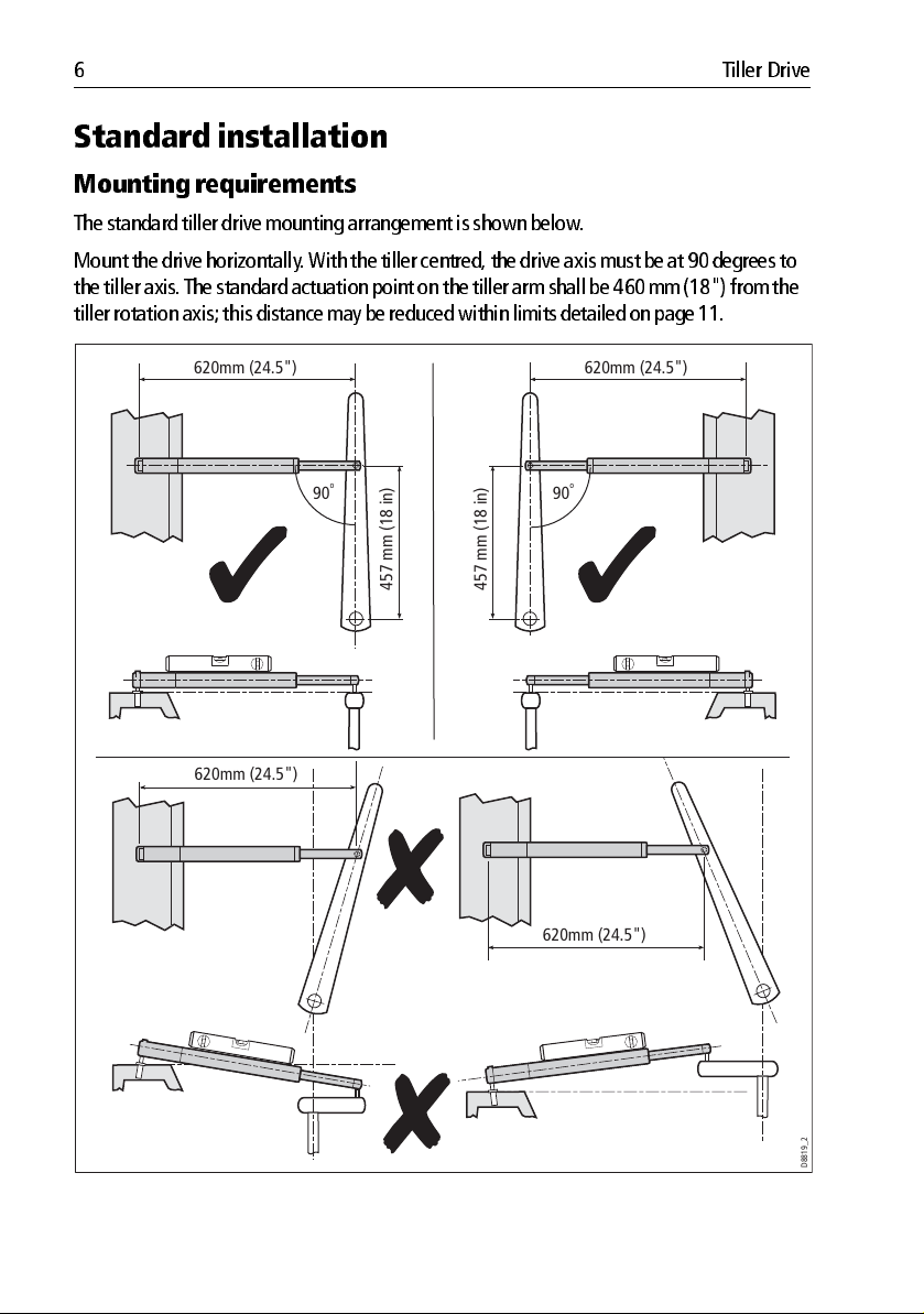
Mounting requirements
The standard tiller drive mounting arra ngement is shown below .
Mount the drive horizon tally . With the tiller cen tred, the drive axis must be at 90 deg rees to
the tiller axis. T he standard actu ation point on th e tiller arm shall be 460 mm (18") from the
tiller rotation axis; this di stance may be reduced with in limits detailed on p age 11.
620mm (24.5")620mm (24.5")
620mm (24.5")
o
90
457 mm (18 in)
457 mm (18 in)
o
90
620mm (24.5")
D8819_2
Page 7

Tiller Drive 7
The installat ion can be adapted to suit a wide variety of configu rations. See also:
•
Drive unit position page 11
•
Accessories page 13
Installation procedure
This proced ure can be followed when neith er accessories or adaption of the drive unit
position are required .
Install the tiller d rives as fo llows:
1. Securely clamp the tiller, mark the pin posit ion and drill the 6 mm (1/4”) hole .
2. Fix the pin in position using a twopart epoxy adhesive.
3. Check the shoulder heigh t of the pin.
1. 2.
Two part
457 mm (18 in)
6 mm
(0.25 in)
12.5 mm
(0.5 in)
3.
12.5 mm
(0.5 in)
Allow epoxy to fully harden
before applying load.
epoxy
adhesive
to fix tiller
pin in
place
4. Mark the sock et position and drill a 6 mm (1/4“) pilo t hole to con firm the thickness of th e
structure. If less than 25 mm, rei nforce with plywood and bond into position. Once cu red
open up the hole diam eter to 12.5 mm (1/ 2”).
5. Fix the sock et in position using a twopart epoxy adhesive .
D8818-2
Page 8

8 Tiller Drive
6. Once the epoxy has fully hardened, fit the tiller dri ve.
4.
620 mm (24.5 in)
457 mm (18 in)
12.5 mm
(1/2 in)
25mm
(1.0 in)
5.
6.
Two part
epoxy adhesive
to fix mounting
socket in place
D8831_2
Page 9

Tiller Drive 9
Installing the socket
1. Cutout and tape the temp late to the bulkhead in the req uired position.
23
2. Drill a 18 mm (
3. Lift off the template remove burrs or shar p edges.
4. Pass th e cable through the bu lkhead and attach to th e socket, makin g sure you connect
each core to the correct pin .
Attach the sock et to the bulkhead usin g the two selftapping screws . Use cable clamps to
secure the drive cable at regular interv als.
/32”) clearance hole and two 2.5 mm (3/32”) pilot holes .
Rear of socket
Drive (blue)
3 stripe terminal
To the
control unit
Tiller drive - socket template
Drill 2.5 mm (3/32 inch)
diameter hole (2 positions)
Terminal
identification
stripes
Drive (brown)
2 stripe terminal
D8840-1
Drill 18 mm (23/32 inch)
diameter hole
D5411-2
Page 10

10 Tiller Drive
Connecting to the course computer
The tiller drive is supp lied with a cord and plug. T o connec t the drive and course computer , the
supplied sock et should be in stalled and a cable ro uted from the sock et to the course comp uter .
1. Measure the required leng th of cable and select the correc t gauge using the follo wing
table:
Cable le ngth Copper are a AWG
Up to 2 .5 m (8 ft)
Up to 4 .0 m (13 ft)
Up to 6 .0 m (22 ft)
1.0 mm
1.5 mm
2.5 mm
2. Route the cable from the so cket to the course co mputer .
Course computer
2
2
2
18
16
14
SEATALK
Brown
POWER IN
RF GND
Blue
D9446-1
Page 11

Tiller Drive 11
Adapting th e installatio n
Drive unit position
The tiller pin and drive pedestal can be mounted between 356 mm and 457 mm (14” 18”)
from the centre of the ru dder stock. 45 7 mm (18”) is the sta ndard distance fo r use on vessels
up to:
• 6 tonnes fully laden d isplacement for the standa rd tiller drive unit.
• 7.5 tonnes fully la den displacement for th e GP tiller drive unit.
Note:
Typically laden displacement is up to 20% greater than manufacturers’ disp lacement figures.
For lighter d isplacement vessels requiring faster turn rates it is possible to i nstall the tiller pin
and drive pedestal closer to the ru dder stock, to a minim um of 356 mm (14“).
Tiller Drive Unit Position Range
620mm (24.5")
90˚
356 mm to 457 mm (14 in to 18 in)
D9291_1
Page 12

12 Tiller Drive
The following table can be used to calcu late the required position .
Drive pin
distance from
rudder stock
457 mm (1 8”)
standard d istance
432 mm (17” ) 33º 8 º per second 79 kgf
406 mm (16” ) 35º 9 º per second 75 kgf
381 mm (15” ) 37º 9 º per second 70 kgf
356 mm (1 4”) 39 º 10 º per second 65 kgf
Max degre es of
helm (with pilot
engaged)
31º 8 º per second 84 kgf
Rate of helm
change Force a t rudder
Page 13

Tiller Drive 13
Accessories
The following accessories may be used to ad apt the tiller drive mountin g to suit different
installation requi rements.
Part Number Description
D003 Pushro d Extens ion 25mm (1")
D004 Pushro d Extens ion 51mm (2")
D005 Pushrod Ext ension 76 mm (3")
D006 Pushrod Extension 102 mm (4")
D007 Pushrod Extension 127 mm (5")
D009 Tiller Br acket 2 5 mm (1")
D010 Tiller Br acket 5 1 mm (2")
D011 Tiller Br acket 7 6 mm (3")
D159 Tiller Br acket 1 02 mm (4")
D160 Tiller Br acket 1 27 mm (5")
D031 Cantilever Sock et
D026 Pedes tal Sock et 38 mm (1.5")
D027 Pedes tal Sock et 51 mm (2")
D028 Pedes tal Sock et 64 mm (2.5")
D029 Pedes tal Sock et 76 mm (3")
D030 Pedes tal Sock et 89 mm (3.5")
D002 Mounting Socket (package of 5 )
D014 Small Thread T iller Pin (package of 5)
D001 Tiller P in (package o f 5)
D014 Small threaded tiller pin 25 mm (1")
D020 Extra leng th tiller pin 71mm (2.8 ”)
D021 Extra leng th thr eaded tiller p in 71mm (2.8” )
Page 14

14 Tiller Drive
Push rod extension
Use a pushrod extension if dimensi on C is greater than 620 mm (24.5”).
1. Select a pushrod extensio n with a length L nearest to C 62 0 mm (24.5”)
2. Unscrew the pushrod end cap
3. Screw on the pushro d extension
4. Screw the pushrod end cap onto the pushr od extension.
C
L
D8812_1
Page 15

Tiller Drive 15
Push rod mountin g
Cantilever socket
Use the cantilever socket if you need to attach the tiller drive to a vertical face (suc h as the
cockpit sidewall).
F
L
1
6_
1
8
8
D
1. Use a hacksaw to cut the rod to length L = F 635 mm (25”).
2. Assemble the mountin g ring, rod and socket.
3. With the drive horizonta l mark the location of the mo unting ring and its holes.
4. Drill three 6 mm (1/4”) diameter clearance holes at th e marked positi ons.
5. Apply a thin co at of silicone sealant to the base of th e mounting ring.
6. Use three 6 mm (1/4” ) diameter bolts , nuts an d washers to att ach the mount ing ring and
backing plate
7. Roughen the en d of the rod and inside of the sock et to provide a key . Then a pply twopart
epoxy adhesive to the rod end an d cap.
8. Place the cap over the rod end, making sure the hole faces upw ards. A llow the adhesive
to harden fully before ap plying a load.
Note:
Note: When the autop ilot is not in us e, you can unscrew the complete rod assembly to leave the
cockpit unobstructed
Page 16

16 Tiller Drive
Pedestal socket
Use the pedestal socket if yo u need to raise the height of the sock et to keep the tiller drive
horizontal.
L
G
1. Select a sock et assembly with a length L, nearest to G 38 mm (1.5” ).
2. With the drive assembled , and the sock et positioned 460 mm (24.5”) from the til ler axis
mark the location of the mounting rin g and holes .
3. Drill three 6 mm (1/4”) diameter clearanc e holes at the marked positions .
4. Apply a th in coat of silicone sealant to the base of the mounting ring.
5. Use three 6 mm (1/4”) diameter bo lts, nu ts and washers to attach the mo unting ring and
backing pla te
Note:
Note: When the autop ilot is not in us e, you can unscrew the complete rod assembly to leave the
cockpit unobst ructed
D8817_!
Page 17

Tiller Drive 17
Tiller brackets
If the tiller is h igher or lower than the mou nting sock et, you can use a til ler bracket to vary th e
tiller pin height so the d rive is horizontal.
D
D8813_1
E
1. If the drive is below the tiller; brack et size equals dimen sion D . If the drive is above the
tiller; brack et size equals dimension E 25 mm (1”).
D8814_1
Page 18

18 Tiller Drive
2. Place the tiller brac ket on the center lin e of the tiller (above or below) and establish the
correct positio n.
3. Mark the centers of the brack et mounting holes.
4. Drill two 6 mm (1/4”) diameter clearanc e holes through the center li ne of the tiller at the
positions ma rked.
5. Attach the tiller b racket using two 6 mm (1/4“) diam eter bolts, n uts and washers.
6. Fix th e bolts in position using twopart epoxy adhesive .
7. When the epoxy is com pletely hardened, fully tighten the nuts .
457 mm (18 in)
90 degrees
D8815_2
 Loading...