

Page 1

Distributed by
Any reference to Raytheon or
RTN in this manual should be
interpreted as Raymarine.
The names Raytheon and RTN
are owned by the
Raytheon Company.
Page 2

Installation & Operating Handbook
Nautech Limiied, Anchorage Park, Portsmouth
Telephone (0705) 693611, Telex 86384 NAUTEC G.
Hampshire, PO3
STO,
England.
Page 3

CONTENTS
Page
1. General Description
1.1.1 Course Computer
1.1.2
Control Unit
1.1.3 Fluxgate Compass
1 .1.4 RuddepReference Transducer
1.1.5
Auxiliary Alarm
1 .1.6 Radio Navigation Interface
Hydraulic Drive Units
1.2
1.2.1 Type 0 Hydraulic Drive
1.2.2 Type 1 Hydraulic Drive
2. Installation
2.1 .l Course Computer
2.1.2 Control Units and Radio
Navigation Interface
2.1.3 Fluxgate Compass
2.1.4 Rudder Reference Transducer
2.1.5
Accessories
Hydraulic Drive Unit
2.2
2.2.1 Type 0 Installation
2.2.2 Type 1 Installation
2.3 Cabling and Power Supplies
2.3.1 Signal Cabling
2.3.2 DC Power Supplies
3. Operation
3.1
Basic Principles
3.2 Controls
3.2.1 Fixed Control Unit
3.2.2 Hand Held Control Unit
3.2.3 Operating Mode Indication
and Course Display
3.2.4
Off-Course Alarm
Functional Test Procedures
3.3
3.3.1 Setting Up
3.3.2 Functional Test Procedure
3.3.3 Drive Unit Test Procedures
10
11
12
13
13
14
14
15
17
2
3
3
3
4 8.
4
4
5
5
10.
5
6
7
7
9
17
18
18
19
20
21
21
21
21
22
6.
Maintenance
Fault Location Procedure 27
7.
Warranty, After Sales
Service
U.K. Service Centres 30
9.
Overseas Representatives 31
26
28
4.
Sea Trials
First Sea Trials
4.1
Rudder Control Adjustment
4.2
5. Operating Hints
5.1
Unsatisfactory Steering
Performance
23
23
24
25
25
Page 4
1. GENERAL DESCRIPTION
Congratulations on choosing the
Autohelm
outstanding self steering capability for a
wide range of modern powercraft
equipped with hydraulic steering.
The PowerPilot uses microprocessor
based technology and easy to use control
pads to give you total command under
autopilot control without the need for
constant adjustments.
The
world’s largest producer of Marine
autopilots with Technical Advice, Service
and Support ready to help you get the
most from your Autohelm.
PowerPilot.
PotierPilot
It offers
is manufactured by the
FLUX GATE
The PowerPilot is modular and designed
for easy installation with flexibility to cope
with the variation of individual craft and
owner specifications. It is supplied as
standard with the course computer, one
control unit, fluxgate compass, hydraulic
drive unit, and rudder reference
transducer. The basic
PowerPilot can be extended to suit
individual requirements. The basic system
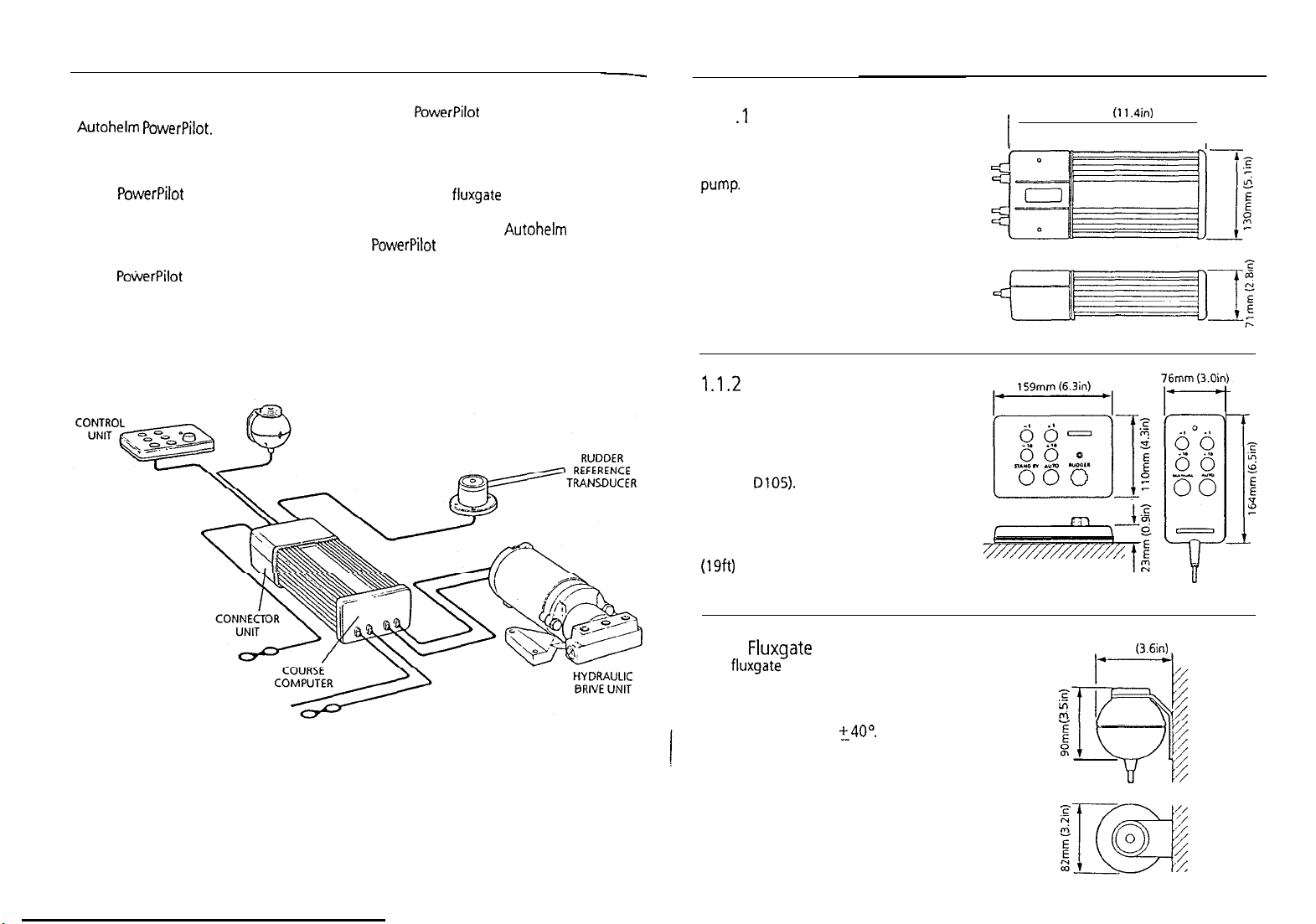
is illustrated below in Figure 1.
Autohelm
1.1 .l Course Computer
The course computer houses the
microprocessor, electronic control circuitry
and power amplifier to drive the hydraulic
pump.
The course computer is splash proof
only and must be mounted in a dry and
protected position.
1 .1.2
Control Unit
The six button control unit is fully
waterproof and is mounted close to the
steering position. It is designed for surface
mounting, or alternatively can be bracket
mounted if required (bracket mounting kit
Cat. No. D105).
A second control unit (Cat. No. 2054)
and a hand held control unit (Cat. No.
2056) can be added to the system. The
hand held control unit is fitted with a 6m
(19ft) wander lead and plugs into a
bulkhead mounted waterproof socket.
288mm
(11.4in)
I
II
Fig. 1 BASIC SYSTEM
2
1.1.3 Fluxgate Compass
The fluxgate compass has been especially
developed for marine application. The
compass contains a gimbal mechanism to
permit accurate readings with pitch and
roll movements up to
is bulkhead mounted below decks and
connects directly to the course computer.
t40°.
The compass
92mm
(3.6in)
z
”
”
3
Page 5

1.1.4 Rudder Reference
Transducer
The rudder reference transducer provides
the course computer with a precise
rudder position. It is mounted on a
suitable base adjacent to the rudder
stock. The interconnecting cable connects
directly to the course computer connector
unit.
1.1.5 Auxiliary Alarm (Cat. No. 2035)
The autopilot is provided with an
automatic off course alarm system which
sounds from all control units and provides
sufficient audible warning under most
conditions. In cases where a high power
alarm is necessary, an auxiliary alarm can
be fitted. The auxiliary alarm is connected
to the main connector unit via a two
core cable.
1.1.6 Radio Navigation Interface
(Cat. No. 2057)
The PowerPilot can be interfaced to any
Loran, Decca or Satellite Navigation
receiver having a suitable cross track error
output to NMEA0180/0182/0183. The
radio navigation interface computes the
course adjustments to enable the
PowerPilot to steer to a selected waypoint.
The unit is waterproof and designed for
surface mounting (normally adjacent to
the Loran/Satellite Navigation receiver). If
required the unit can be bracket mounted
using the bracket mounting kit
(Cat. No. D104).
4
-1
82Smm
(3.2%)
213mm (8.37in)
1.2 HYDRAULIC DRIVE UNITS
The PowerPilot is available with one of
two hydraulic drive units, depending on
the size of the vessel and the
displacement of the ram.
The vessel size and displacement
recommendations given below apply to
directly driven steering systems. When a
power steering system is fitted the vessel
1.2.2 Type 1 Hydraulic Drive
The hydraulic drive unit consists of a
precision gear pump with integral valve
block driven by a continuously rated servo
motor. The pump drive motor is connected
directly to the course computer which also
regulates peak pump pressure and
eliminates the need for end stroke limit
switches.
size and displacement recommendations
can be ignored.
1.2.1 Type 0 Hydraulic Drive
The type 0 hydraulic drive unit consists of
a twin cylinder piston pump powered by a
small but powerful reversing electric
motor.
The high volumetric efficiency of the
piston pump provides precise control,
with the twin pistons offering smoother
and quieter operation than would be
found with a single cylinder design.
Descriotion Size
Maximum Vessel Size 8m
Maximum Vessel
Displacement 3000 Kq (6600
Maximum Ram Capacity
Minimum Ram Capacity
Regulated Peak Pressure
Peak Flow Rate (Unloaded) 490cdmin (30inYmin1
Power Consumption
(Typical Averaqe)
km
Type
Double Ended (Balanced)
(26ft)
13Occ (8.0ina)
5Occ (3in’)
30 bar (450lb
1.5-2.5 amps
Ibs)
in?)
Description Size
Maximum Vessel Size 1 lm (36f~)
Maximum Vessel
Displacement 5500 Kg (12000
Maximum Ram Caoacitv 23Occ (14in’)
Minimum Ram Capacity
Reaulated Peak Pressure
Peak Flow Rate
(Unloaded)
Poher Consumption
(Typical Average)
Ram Type
I-
13Occ (8inj)
50 bar (75ODs.i)
11
OOcdmin)
(67inYmin
3.5-6 amps
Single or Double Ended
(unbalanced or balanced)
190mm (7.5in)
Ibs)
w
Page 6

2.
INSTALMTION
WARNING
The Autohelm PowerPilot requires correct
installation if it is to provide accurate safe
self steering. Whilst designed for simple
installation we strongly recommend that
the system should be installed
professionally or alternatively professional
advice be obtained if you intend to install
the system yourself.
The manufacturers can accept no
liability for any claims arising from
incorrect installation or product useage.
2.1.1 Course Computer
Mounting Position - Below Deck
The course computer should be positioned
in use we strongly recommend the use of a
protective cover (optional extra
Cat. No.
in a dry protected area of the vessel free
from high operating temperatures and
excessive vibration. It can be mounted in
any attitude. Care must be taken to allow
at least
15mm
(6in) clearance all round to
aid heat dissipation from the power
amplifier in the unit. Do not mount in the
engine room.
WARNING
Safe operation of the PowerPilot requires
that the control unit be mounted within
easy reach of the helmsman when in the
normal steering position. Position the
control unit to ensure this requirement is
met.
DO NOT position the course computer
so that it will:
l
Receive any direct water splash/spray
(from Bilge/Hatch etc).
l
Be liable to physical damage from heavy
items.
0
Be covered by other equipment or
Mounting Instructions
The unit is attached with reusable positive
locking pads. In most cases, the pads may
be stuck directly onto the mounting
surface.
l
onboard gear.
l
Be close to major sources of
transmitted energy (Generators/S%
radios, Aerial Cables etc).
Mounting Instructions
l
Remove Terminal box lid (Fig. 2).
l
Unscrew two internal thumb retaining
l
nuts (Fig. 2).
l
Unplug terminal box and mounting
spine.
l
Position terminal box and mounting
spine in correct location, mark off and
pilot drill for the 5 self tapping screws
supplied (Fig. 3).
l
Screw terminal box and mounting spine
into place.
l
Plug course computer unit to terminal
box. Retighten thumb retaining screws.
The course computer is now ready for
wiring (see 2.3).
DlOl).
Using the template supplied, select the
control unit position, mark off and drill
the
17mm (5/8in)
hole for the
interconnect cable.
Attach the positive-lock pads to the rear
of the control unit (Fig. 4).
2.1.2 Control Units
Mounting Position
be mounted close to the steering stations.
The unit is fully water-proof and suitable
for external location. If the control unit is
permanently exposed when the boat is not
-
Control units must
l
Thoroughly clean the mounting surface
with alcohol (or equivalent) and allow
to dry.
7
Page 7

Instructions
l
Thread the interconnect cable through
the
17mm
(518in) hole, peel off the
l Using the template supplied mark off
backing from the pads (Fig. 5).
l
Press the unit onto the mounting
surface maintaining pressure for 30
l
seconds to ensure a strong bond.
The control unit interconnect cable is
l
now ready for connection to the course
computer (See 2.3).
l Note An additional foam seal must be
Where the control unit is to be mounted
to a painted, varnished or untreated wood
l Carefully align the control unit with the
surface the carriers supplied should be
used to provide a sound bonding surface
for the
mounting
pads.
(Fig. 6).
and drill the 17mm
(518in)
hole and
mark off and pilot drill the fixing holes
for the carriers.
Screw the holders
inio
position using
the self tapping screwS provided.
Clean the holder surface with alcohol
(oiequivalent) and stick the positive
lock pads into place (Fig. 6).
used in this method to provide sealing.
holders and press firmly into place to
secure a positive attachment.
Removing a Control Unit
l
Using a flat lever gently unlock the
securing pads starting at one corner.
l
Do not use excessive force.
0
The unit may be re-attached by
pressing
it’back
onto the security pads.
fluxgate
(2ft6in)
compass in order to avoid deviation of
both compasses. The
be positioned as far away as possible from
large iron masses, such as the engine and
2.1.3 Fluxgate Compass
The
fluxgate
a convenient bulkhead using the self
tapping screws provided. Unscrew the top
cap to release the compass housing from
the mounting bracket (Fig. 7). Screw the
bracket to the bulkhead using the self
tapping screws provided and finally
attach’the compass body to the mounting
bracket.
Correct positioning of the fluxgate is
crucial if ultimate performance from the
autopilot installation is to be achieved.
The
compass may be attached to
fluxgate
should ideally be positioned
re-
other magnetic devices which may cause
deviation and reduce the sensitivity of the
sensor. If any doubt exists over magnetic
suitability of the chosen site, the position
may be surveyed using a simple hand
bearing compass. The hand bearing
compass should be fixed in the chosen
position and the vessel swung through
360°. Relative differences in reading
between the hand bearing compass and
the vessel’s main steering compass should
ideally not exceed 5O on any heading.
Fig.
as near as possible to the pitch and roll
centre of the vessel in order to minimise
gimbal disturbance (Fig. 8).
Fig. 7
It is very important to ensure that the
is positioned at least 0.8m
away from the vessel’s steering
fluxgate
must also
8
.
0.3c to 0.5L
.
-I
L
I
+i
Fig.
6
When the installation is complete the
fluxgate
compass should be
approximately aligned with the vessel’s
centre line by rotating the body until the
arrows on the joint line face the bows
(Fig. 9).
8
9
Page 8

Fig. 9
the rudder reference unit arm and tiller
arm. If it is more convenient, the rudder
reference unit may be mounted upside
down (label downwards), but if this is
done, the red and green wires must be
reversed in the connector unit.
It is important to ensure that
dimensions A and B (fig. 11) are the same
at both points and that when the rudder
is amidships the unit arm is opposite the
cable gland and makes an angle of
90°
with the connecting bar.
2.1.5 Accessories
The most comprehensive installation is
illustrated below in
Fig.
12
CONTROL
fle
Fioure
=c5
12.
FLUX GATE
-
”
RADIO NAVIGATION
INTERFACE
RUDDER
Fig. 11
Installation Precautions
Correct installation of the course
computer and fluxgate compass is vital to
the successful performance of the
Autohelm Pow&Pilot. The installation
A
precautions must be heeded if poor
performance or even failure of the
autopilot is to be avoided.
2.1.4 Rudder Reference
Transducer
The rudder reference unit must be
mounted on a suitable base adjacent to
the rudder stock (Fig. 10) using the self
tapping screws provided. The base height
must ensure correct vertical alignment of
Fig.
10
TILLER
AR,M
8
I
I
B
y-
.
I
I
I
e
/
-
r-l
A
400
Having selected a suitable position
(Fig.
lo),
the interconnecting link A may
be cut to length and the linkage fastened
ensuring that the locking nuts B are
secure. The tiller arm should be tapped
M6 to a depth of
2Omm
(13/l 6in) or
through drilled to accept the ball joint
supplied. The rudder should then be
moved from side to side to ensure the
linkage is free from any obstruction,
Radio Navigation Interface
(Cat. No. 2057)
This is installed using the same procedure
as given for the control unit. (See 2.1.2).
Auxiliary Alarm (Cat. No. 2035)
The auxiliary alarm unit is waterproof and
may therefore be mounted in any
position. The alarm unit is supplied with a
terminal block to connect a two core
Remote Control Unit
The remote control socket is pre-wired
with the interconnecting cable. A 22mm
(7/8in) diameter hole should be bored
through the mounting panel and the
interconnection cable to the course
computer. A 22mm
bored through the mounting panel/deck
to pass through the two way connector
block and interconnecting cable (Fig. 14).
socket screwed into position using the
four self tapping screws provided (Fig. 13).
screwed into position using the four self
tapping screws provided. A foam seal on
the alarm mounting flange will ensure a
watertight joint to the mounting surface.
Fig. 14
HYDRAULIC
DRIVE UNIT
(718in)
hole
should.be
Finally, the alarm unit should be
11
Page 9

2.2 HYDRAULIC DRIVE UNIT
General guidelines
The hydraulic drive unit should be
mounted clear of spray and the possibility
of immersion in water. It should be
located as near as possible to the
hydraulic steering cylinder. It is important
to bolt the hydraulic drive unit securely to
a substantial member to avoid any
possibility of vibration that could damage
the inter-connecting pipework.
There are three basic types of hydraulic
steering system, and these are illustrated
in Fig. 15. Typical connection points for
the drive unit are shown in each case. In
all cases it is strongly recommended that
the steering gear manufacturer be
consulted.
Minimisation of hydraulic fluid loss
during connection of the drive unit will
help to reduce the time and effort
required later to bleed the system of
trapped air. Absolute cleanliness is
essential since even the smallest particle
of foreign matter could interfere with the
correct function of precision check valves
in the steering system.
Fig. 15
:
T.40 Line
System
%
RESERVOIR
completed the hydraulic pump may be
operated by switching the control unit to
Auto and operating the +
course change buttons. Greater motor
movements will be obtained if the rudder
control is set to maximum.
bled according to the manufacturer’s
instructions. From time to time during the
bleeding process the drive unit should be
run in both directions to clear trapped air
from the pump and inter-connecting pipe
work.
steering will feel spongy particularly when
the wheel is rotated to the hardover
position. Trapped air will severely impair
correct operation of the autopilot and the
steering system and must be removed.
has not been necessary to keep track of
the connection sense to the hydraulic
steering circuit since operating sense of
the autopilot can be corrected if necessary
by reversing the pobrity of the pump drive
motor connections (see section 3.3.1).
When the installation has been
10”
and - 10’
The hydraulic steering system should be
If the air is left in the system the
During the installation of the system it
r(
2.2.1 Type 0 Installation
The Type 0 pump must be mounted
vertically with the mounting flange bolted
to a suitable horizontal surface using four
6mm
(114in)
All ports are tapped
1/8in B.S.P. to 1/4in
included to convert to
bolts.
1/8in B.S.P.
N.PT.
adaptors are
N.PT.
where
Three
required. The sealing washers supplied
should be placed between the fitting and
the pump (Fig. 16).
It is recommended that
1/4in
fittings or
larger are used throughout to minimise
transmission losses.
Fig. 16
’
STEERING
CYLINDER PORTS
l/h B.S.P.
SEALING
The two cylinder ports are positioned
opposite one another on the pump body.
The reservoir port is marked R and is at
45“.
All connections to the pump should
be made with flexible hose.
Important Note
All connections in the reservoir line
must be sound as any air introduced
to this line will seriously degrade
pump performance.
Bleeding
The type 0 pump is sensitive to trapped
air, and care must be taken during
installation and commissioning to remove
it. Before connecting the hoses to the
pump:
bleed the system, turn the helm pump in
opposition. This will help any air expelled
from the hydraulic pump rise to the helm
pump reservoir.
2.2.2 Type 1 Installation
The Type 1 pump should be mounted on a
suitable horizontal surface.
114in B.S.P.
included to convert to
required (Fig. 17). The sealing washers
supplied should be placed between the
fitting and the pump (Fig. 18).
l
Ensure all hoses are filled with oil
l
Prime the pump ports with oil
When operating the hydraulic pump to
All ports are tapped 1/4in
to
114in N.PT.
Fig. 17
B.S.P.
Three
adaptors are
N.PT.
where
l/din N.P.T. FirriNG
N.PT. ADAPTOR
SEALING WASHER
Page 10

.
I
2.3 CABLING AND POWER
SUPPLIES
2.3.1 Signal Cabling
Cable interconnections between all sub
system modules are shown schematically
(in Figs 1 and 12). All peripheral units
connect to the connector unit where they
are permanently hard wired to
coded connector blocks situated on a
central printed circuit board (Fig. 19).
fitted with ten blanking discs (Fig. 20).
which are easily pressed out and replaced
with each peripheral unit fixing kit
/T
-----T
colour
The end face of the connector unit is
by the special rubber grommets supplied
_
,
_
Fig.
21
KEY
40mm
0 WHlTE
0
YELLOW
0
GREEN
@RED
e
BROWN
(Fig. 2 1). After cutting the
interconnecting cable to length (Fig. 21),
it may be passed through the inserted
rubber grommet and prepared for
connection to the relevant connector
block (Fig. 19).
Each connector block is clearly
identified on the printed circuit board and
each wire position is identified by
coloured
dots which match the individual
wire colours. The cable screen should be
connected to terminals identified by a
white dot.
Each peripheral unit is supplied with 6m
(20ft) of interconnecting cable. Additional
cabling can be supplied in
lengths as
Cat. No.
DO06
(Two
DO87
flhree core screened)
DO88
(Four core screened)
follows:-
core unscreened)
12m (4Oft)
Used On
Alarm, Electronic
power supply and
Clutch
Control
units,
Radio Navigation
Interface
Fluxgate Compass
and
cut
The total length of screened core cable
connected to the serial bus (connectors
Al
-A5)
should not exceed 30m (1
OOft).
Similarly, the total length of
interconnecting cable to the
fluxgate
should not exceed 2Om (60ft). If it is
necessary to exceed the above maximum
length recommendations, please consult
Nautech’s Product Support Department
for specific advice. In general the length
of interconnecting cables should be kept
to an absolute minimum to reduce the
possibility of interference by other
electronic equipment.
All cables should be run at least 1 m
(3ft) from existing cables carrying radio
frequency or pulsed signals, and should
be clamped at
0.5m
(1 .Sft) intervals.
2.3.2 DC Power Supplies
(Fig. 22).
Flexible connection tails fitted with
insulated spade connectors are
with the course computer to connect
main power
supply
(Blue and Brown) and
drive unit motor connections (Red
Black).
All four flexible wire tails are
preconnected to a four-way heavy duty
terminal block for connection to the main
power cabling. Similarly, the drive Ullil
supplied with flexible tails for the motor
power connection (Red and Black).
Before commencing power cabling,
interconnecting terminal blocks should be
screwed into a position where they
remain dry and protected. When pl,~nning
the position of the course computer
(ref.2.1.1).
it is important to reduce
overall length of heavy power cable
between the drive unit and the vessel’s
central power distribution panel to a
minimum.
Excessive lengths will generate losses in
the cable and will reduce system
performance. In addition, the cable
between the course computer and drive
unit must be less than 5m (16ft).
Having sited the course computer,
measure the total cable length between
the drive unit and the vessel’s central
distribution panel and select the
appropriate cable size from the table
below.
Total
Cable
Length
Up to 7m
Up to 1
Up to 16m 8410.3
Cable
Type
5010.25
Om 5610.3
Copper
2.5mm’
4.0mmz
6.0mml
Area
SUpplicd
a111j
will
the
Cable
Gauge
14 f’!J’srG
12
lOAWG
ttle
iS
all
length
AV’&
Page 11

3. OPERATION
The power supply must be led from the
main distribution panel and protected by
means of a 25 amp fuse or current
overload trip switch. A separate 5 amp
fuse must be fitted in the electronic
power supply cable.
Fig.
22
CIRCUIT BREAKER
25AMP- 12V
HEAVY
DUTY
POWER SUPPLY
OUTPUT
TO MOTOR
It is very important that both the
electronic and heavy duty power supplies
are isolated by a switch in the positive
supply line.
When connecting the power supplies to
the main distribution panel and to the
course computer spade connectors, it is
essential that the polarity is correct
(Brown positive, Blue negative).
ELECTRONIC
POWER
SUPPLY
3.1 BASIC PRINCIPLES
The following description of the
Autohelm
operation will help you to fully understand
its controls.
1
J
Deviation from course is continuously
monitored by a sensitive
and corrective rudder is applied by the
drive unit to return the vessel to course.
The applied rudder is proportional to
course error at any time and thus when
the course is restored the rudder will be
neutralised.
applied for a given off-course error must
match both the steering characteristics of
the vessel and speed through the water. A
vessel with a small rudder for example,
will require more corrective helm than a
similar sized vessel with a larger rudder.
Similarly, a high speed power boat will
require considerably less corrective helm
at planing speeds than it will at lower
displacement speeds.
When changes in vessel trim occur due
to variations in wind pressure or engine
throttle setting the course can only be
maintained by the application of
permanent rudder.off-set (standing helm)
to restore balance. If permanent rudder
off-set is not applied to restore balance
the vessel will bear on to a new heading.
Under these circumstances the
PowerPilot detects that the original course
is not being restoredand continues to
apply additional rudder off-set in the
appropriate direction until the vessel
returns to the original heading. Automatic
trimming capability ensures that the
originally set course is held irrespective of
any changes in balance that may occur
during the course of a passage.
computer also continuously monitors the
pattern of applied rudder correction and
can distinguish unnecessary repetitive
corrections caused by pitch and roll of the
PowerPilot’s
Autohelm
principle of
fluxgate
The amount of rudder
Autohelm
PowerPilot’s
central
compass
vessel from those necessary to maintain
the selected heading. If unnecessary
repetitive corrections continue the
computer will automatically neglect them
so that autopilot activity and power
consumption is continuously optimised at
minimum levels.
The high degree of control automation
made possible by the system’s central
micro computer simplifies user control to
a series of push button operations.
16
17
Page 12

3.2.3 Operating Mode indication
and Course Display
The operating mode of the autopilot is
indicated by a flashing red LED, as
summarised below:-
OPERATING MODE
STAND BY
Autopilot switched on but
not engaged
AU-t-0
Autopilot engaged to steer
compass heading
MANUAL
Hand held control power
steering in operation
ii@
ON
20
0
OFF SECONDS ’ ! : : : :
LED FLASHING CODE
)j
~~@j~fzJjj@
y?J
l
3.2.4 Off-Course Alarm
When the autopilot is set to Auto mode a
built in off-course alarm is automatically
set up. The off-course alarm will sound
from all control units when the vessel
deviates for any reason from the original
course by more than
seconds. If an auxiliary alarm is fitted this
will also be sounded after a one minute
delay to allow the watchkeeper to take
corrective action.
The alarm will be silenced if the vessel
returns to within 1 So of the original
course. If the vessel does not return within
course limits the alarm can only be
silenced by disengaging the autopilot and
resetting a new course.
f$j
3.3 FUNCTIONAL TEST
15“
for over 20
PROCEDURES
The following functional tests and set up
procedures must be carried out before
sea trials are attempted.
3.3.1 Setting Up
Switch On
Switch on the electrical supply from the
main panel. All control units will emit a
short beep tone to indicate that the
computer is now active. The autopilot will
start up in Stand By mode.
L;
Operating Sense
The operating sense of the autopilot can
be checked as follows:-
* Select Auto
l
Select + 10 which should move the
rudder a few degrees to produce a turn
to starboard.
If this does not occur, correct operating
sense can be restored as follows:-
* If the rudder immediately drives hard
over to starboard, the red and green
wires of the rudder reference
transducer should be reversed in the
connector unit.
If the rudder immediately drives hard
over to port, the motor connections
between the course computer and
drive unit should be reversed.
l
If the rudder drives a few degrees to
port, reverse the motor connections,
and reverse the red and green wires of
the rudder reference transducer.
N.B. Reversal of the motor connections
should be permanently made at one of
the main terminal blocks and not by
reversing the spade connector flying leads
to the course computer.
3.3.2 Functional Test Procedure
l
Switch on and note that all control
units are live and signalling Stand by
mode.
0 Key Auto on any fixed control unit and
note that Auto mode is indicated on
all control units.
l
Key course change commands from all
control units noting that
corresponding helm movements occur.
0 Key Manual on the hand held control
unit (if fitted) and note that Manual
mode is signalled from all control units.
l
Key power steer commands via the
course control keys of the hand held
control unit and note that
corresponding incremental helm
movements occur.
l
Key Stand by
The automatic trimming capability of
the autopilot can be observed by the
following test:
Key Auto followed by a 1 O” course
change to starboard. This effectively
simulates a condition where the need for
standing helm has developed and the
vessel is not returning to course. You will
notice that an initial fixed helm movement
is applied and that after a short interval
the drive unit will continue to apply
further incremental helm movements. If
21
Page 13

4. SEA TRIALS
left in this condition the rudder will
l
eventually be driven hard over. If, however,
the vessel were moving through the
water, the progressive application of
0 Check that all unions are tight and
additional helm would eventually return
the vessel to the correct course with the
necessary standing helm applied. Return
to course can be simulated by keying
-
10
(to return to the current heading). The
progressive application of standing helm
will cease when the fluxgate senses that
the course error has been removed.
Current Limit and Cutout
When the rudder is driven onto end stops
drive to the hydraulic pump may cut out
after a few seconds. This is normal. Drive
will only be restored if the rudder moves
away from the end stop or if drive is
required in the opposite direction.
3.3.3 Drive Unit Test Procedures
Before attempting sea trials it is important
to check that the vital link with the
steering system provided by the hydraulic
pump and rudder reference transducer
are free from obstruction and operating
correctly.
Warning
When the steering system is being moved
manually or under drive from the
autopilot do not touch any part of the
system. The forces exerted are
considerable and could cause injury.
With an assistant to turn the main
steering wheel get into a position where
the tiller and rudder reference transducer
can be seen.
l With the autopilot in Stand by turn
the sheering wheel from hard over to
hard over.
l
Check that the rudder reference
transducer and linkage do not foul any
part of the steering mechanism or
vessel’s structure.
0 Select Auto and use the + 10 button
to drive the rudder hard over (use’
maximum rudder setting).
l Use the
-
10 button to drive the
rudder hard over in the opposite
direction.
22
PowerPilot will only reach the designed
levels if the installation of the hydraulic
pump and rudder reference transducer is
correctly engineered and adjusted. It is
strongly advised that these be checked
before sea trials.
Check that the steering ram moves
smoothly and that there is no excessive
play.
there is no seepage of hydraulic fluid.
The performance of the
Autohelm
Initial sea trials should be carried out in
calm conditions with plenty of sea room.
The previously conducted functional test
will have verified that the autopilot is
operating correctly and that you are
During the first minute of operation, it will
be noticed that repetitive movements of
the vessel are gradually neglected until
finally the autopilot will respond only to
true variations in course.
familiar with all of its controls.
Set the rudder control on all control
units to minimum.
Initial sea trials on fast planing vessels
the sea state control is automatically reset
whenever a 1 O0 course change is
selected.
should be conducted at no more than half
engine speed. Minimum setting of the
rudder control should provide stable
steering performance.
Fine setting of the rudder control is
Automatic Trim Control
The Autohelm
corrects for trim. No adjustment of the
pilot is necessary.
discussed later (4.2).
Automatic Trim is cancelled and the
4.1 FIRST SEA TRIALS
During first sea trials, the vessel will be
constanfly changing heading, and it is,
therefore, very important to maintain a
constant look-out. The following initial
trial procedure is recommended:@ Steer on to a compass heading and
hold the course steady.
0 Press Auto to lock on to the current
heading. In calm
perfectly constant heading will be
sea
conditions a
Autohelm
correct trim for the new heading. This
process takes approximately one second
per degree of course change. It should be
noted that if a large course change is
keyed in (greater than 60°) the pilot will
not assume the final selected course
immediately. The vessel will come to
within say
will only settle onto course when the
Automatic Trim has been fully established.
maintained.
0 Alter course to port or starboard in
multiple increments of 1 and 10
degrees from any control unit. Course
changes should be prompt and
without any sign of overshooting.
l
If a hand held control unit is fitted key
procedure is adopted for large course
changes.
l
l
l
0
Manual to change over to remote
power steering. Practice power
l
steering using the four course control
keys..
0 Press Stand by to disengage the
autopilot for return to hand steering.
course changes only whilst steering
manually. In this way any obstructions or
other vessels may be cleared properly and
Automatic Sea State Control
During the sea trial, the operation of the
automatic sea state control can be
due account taken of the changed wind
and sea conditions on.the new heading
prior to engaging the pilot.
observed. When the autopilot is initially
engaged in Auto mode the autopilot will
respond to all pitch and roll movements.
To ensure precise course adjustments
PowerPilot
automatically
After each course change the
PowerPilot
10”
will re-establish the
of the desired course and
It is recommended the following
Note required new heading
Select Stand by and steer manually
Bring vessel onto new heading
Select Auto and let vessel settle onto
course
Bring to final course with 1
0
increments.
It is sound seamanship to make major
23
Page 14

5. OPERATING HINTS
4.2 RUDDER CONTROL
ADJUSTMENT
The rudder control setting recommended
on page 22 will provide stable control for
initial sea trials. However, power craft can
vary widely in their response to the helm
and further adjustment of the rudder
control setting may improve the
Autohelm’s steering characteristics.
An excessively high rudder control
setting results in
recognised by the vessel swinging from
side to side of the automatic heading
accompanied by excessive rudder
movement. In addition, distinct overshoot
will
be observed when the course is
oversteer
which can be
higher speed craft and when it occurs can
be corrected by reducing the rudder
control setting. In excess of 30 knots, a
reduction by at least two positions can
often be required within 45“ of North.
Planing Craft
On
wide speed range, the rudder control
setting often requires reduction at higher
speeds where steering effectiveness is
increased. Oversteer can be extremely
violent at planing speeds and it is
recommended that the rudder control
setting is reduced before opening the
throttle.
changed. This condition can be corrected
by reducing the rudder control setting
(rotating rudder control anticlockwise).
Similarly, an insufficient rudder control
setting results in
understeer
which gives
sluggish steering performance and is
particularly apparent when’changing
course. This is corrected by increasing the
rudder control setting (rotating rudder
control clockwise). These tendencies are
most easily recognised in calm sea
conditions where wave action does not
mask basic steering performance. The
rudder control setting is not over critical
and should be set to the lowest setting
consistent with accurate course keeping.
This will minimise actuator movements
and hence reduce power consumption.
It may be noticed that the autopilot
tends to be a little less stable on northerly
headings in the higher latitudes of the
northern hemisphere (and converse!y
southerly headings in the southern
hemisphere). This is caused by the
increasing angle of dip of the earth’s
magnetic field at higher latitudes which
has the effect of amplifying rudder
response on northerly. headings. The
tendency towards northerly heading
instability is usually more .obvious in
24
fast planing craft which operate over a
Autohelm
PowerPilot’s central course
computer continuously optimises
automatic steering performance
l
eliminating the need for operator
supervision.
It is, however, very important to
understand the effect of sudden trim
0
changes on steering performance.
At planing speeds, where only a small
proportion of the hull is in contact with
the water, variations in wind speed and
direction can produce significant changes
in trim. Similarly, variations in vessel
attitude and engine settings also produce
trim changes. When a change in trim
l
l
l
l
occurs the automatic trim compensation
system requires at least 120 seconds to
l
apply the necessary rudder off-set to
restore the automatic heading. In gusting
conditions, therefore, particularly when
the wind is forward of the beam, the
If vessel wanders under pilot control
l
course may tend to wander slightly.
Passage making under automatic pilot
l
is a very pleasant experience which can
lead to the temptation of relaxing
permanent watch. This must always be
l
avoided no matter how clear the sea may
appear to be.
5.1 UNSATISFACTORY STEERING
PERFORMANCE
If the
Autohelm
correctly specified, installed in accordance
with the instructions and adjusted
correctly it will provide outstandingly
good steering precision over a very wide
range of wind and sea conditions.
If the performance falls below your
expectations and the pilot appears to be
working correctly the fault will normally
be found by carrying out the simple
checks outlined below. Before reporting
your difficulties to an
please check the following:-
* Have the test procedures and
adjustments detailed in Section 3.3
PowerPilot has been
Autohelm
specialist,
been carried out correctly? Check
again.
Has the
fluxgate
compass been
installed in an area free from large
magnetic deviation? If in doubt use a
hand bearing compass to check.
If performance has changed recently
has a magnetic influence been
introduced near the
-
anchor/chain/radio equipment/
fluxgate
compass?
loudspeaker/tools/AC. generator, etc.
Is battery voltage correct?
12~.
Are fuses intact and of correct rating?
Are circuit breakers engaged?
Is wiring of correct diameter and are
screw connectors firmly tight?
If pilot fails to hold course - check
rudder setting at control units.
Verity that hydraulic pump is correct for
size and type of vessel.
Check steering ram and actuator are of
compatible type and bleed system to
remove air.
Check rudder reference transducer
linkages for security and correct
alignment.
25
Page 15

6. MAINTENANCE
7. FAULT LOCATION PROCEDURE
The autopilot is one of the most used and
hardest working items of equipment on
board, and therefore must receive its fair
share of attention and routine
maintenance.
Regular inspection of the installation is
recommended in the following areas
where applicable.
1. Check that Hydraulic Steering systems
are free from leaks and trapped air.
Bleed when necessary to remove air
from the system.
2. Check that all inter-connecting cable
terminals are fully tightened and
corrosion free.
3. Check that external waterproof sockets
are capped when not in use and
periodically spray with
similar) to protect from corrosion.
4. Check that the heavy power supply
cable connections are tight and free
from corrosion.
WD40
(or
Autohelm PowerPilot has been designed
to achieve very high standards of reliability
combined with ease of servicing.
If a fault should appear, please double
check that all connections in the
connector unit are sound and that the
heavy power cable connections are tight
and free from corrosion. If you are
satisfied that all connections are sound,
the simple check procedure tabulated
below will assist you to locate the most
likely fault area.
Since the course computer houses the
majority of the electronic control system
there is a high probability that if an
electronic fault has occured it will be
INSTALLATION
HAVE ONLY ONE
DO RED KEYS
EMIT BEEP TONES
WHEN PRESSED?
located in this area. The course computer
unplugs easily for servicing (Section
2.1.1).
suitable lever to separate the pads starting
at one corner. Do not use excessive force.
Disconnect from the connector unit and
withdraw the interconnecting cable
(Section 2.1.2).
returned to your nearest service agent.
Nautech’s Product Support Department in
the U.K. or your own National distributor
who will also be able to provide expert
assistance.
Control units are removed using a
The faulty unit should be removed and
If any difficulties arise, please consult
FAULT OCCUR
IN ONE CONTROL
26
27
Page 16

8. WARRANTY, AFTER SALES SERVICE
LIMITED WARRANTY
Nautech or its appointed Distributors or
Service Centres will, subject to the
conditions below, rectify any failures in
this product due to faulty manufacture
which becomes apparent within twelve
months of its purchase date.
Equipment used in the country of
purchase should be sent directly to the
authorised Distributor for that country or
its appointed Service Centres. The product
will then be service free of charge and
returned promptly direct to the sender.
Equipment used outside the country of
purchase can be either:-
a. Returned to the Distributor or Dealer in
whose country of from whom the
equipment was originally purchased -it
will then be serviced free of charge
and promptly returned direct to the
sender, or
b. The product can be returned freight
pre-paid to the authorised Distributor
or its appointed Service Centres in the
country in which the product is being
used. It will then be serviced and
returned direct to the sender on the
basis that the Distributor or Service
Centre will supply any parts used free
of charge but the sender will be
invoiced for the necessary labour and
return shipment at the local rate.
CONDITIONS
The warranty is invalid if:-
a. The product has been misused,
installed or operated not in accordance
with the standards defined in this
manual.
b. Repairs have been attempted by
persons other than Nautech approved
Service personnel.
FULL INTERNATIONAL
WARRANTY
Nautech or its appointed Distributors or
Service Centres will, subject to the
conditions below, rectify any failures in
this product due to faulty manufacture
which become apparent within twelve
months of its purchase date wherever the
vessel and the product may be operated.
CONDITIONS
1. The product must be installed aboard
2. The product must be installed in
3. The installation must be carried out by
4. The Warranty Registration Card must
5. The Full International Warranty is
CLAIM PROCEDURE
1.
the vessel in the country of purchase.
accordance with the recommendations
issued by Nautech Ltd.
an installer approved by Nautech:
alternatively the installation must have
been inspected and approved by
Nautech or its approved installer.
be completed by:-
0
The Owner or User
l
The Dealer supplying the product
0
The Installer
invalid if:(a) The product has been misused, or
installed or operated not in
accordance with standards defined
in this handbook.
(b) Repairs have been attempted by
persons other than Nautech
*approved Service personnel.
(c) The warranty card has not been
completed correctly or is not
accompanied by proof of purchase.
The product should be sent direct to
Nautech or its appointed Distributor or
Service Centre nearest to the vessel.
The completed Warranty Card and
proof of purchase must accompany
the claim. The product will then be
serviced free of charge and returned
promptly direct to the sender.
2.
Nautech,‘its
Centres, are not liable for any charges
arising from visits to the vessel not to
attend to the product, whether under
warranty or not, nor for sea trials or
any other work associated with the
installation. The right is reserved to
charge for any such services at the
local rate.
Distributors and Service
AFTER SALES SERVICE
Your
Autohelm
give you long service and reliable
performance wherever you sail. To’ensure
that you can always receive prompt and
expert attention in case of any difficulty,
Nautech has established a worldwide
network of AUTOHELM SERVICE
CENTRES.
Please contact your nearest Service
Centre for assistance.
ready:-
* Your Warranty Card
l Proof of Purchase
PowerPilot is designed to
Always
have
28
29
Page 17

9. SERUICECENTRES - UK,Eireand Channel Islands
10. OVERSEASREPRESENTATIVES
Ponsmo;th
Hdmphwe
0705 693611
PortsmouthlChichester
Harbour
Greenham Marine Ltd
EmrwonhYacht Harbour
Thaney Road
Emsworth
Hampshire
0243378314
Chlchesrer Marina
Chichester
vuest Surseex
0243 511070
Hamble Rlverl
Southampton Water
a K Electra Marine
Ft,; ;;ard
WaMsh
Hampshire
o4a952170
Hudson Marine Electronics
MercuryYa~ht Harbour
Sdtchell Lane
Hamble
liampd-lire
0703455129
Lecmar Marine Electronics
Arcalta Marine
COWS
low
0983293996
&
Lymlngton/Poolr
Greenham Marine Ltd
Klog Saltems Lane
Lymmgton
Hampshire
0590 75771
Danlea
Electronics
Cobk Quay
PO&
DOnet
0202673880
Greenham
Quay West Mama
z&y
Quay Road
DO&et
0202676363
aumin
Marine Electronics
OS4
8&i
3321
MarineLtd
Greenham Marine Ltd
COXKk
Pfymwth
0752 228114
Marine Electronics
Putiige
auckfdnd
arwer
aideford
Norlh
Own
0805
22870
Ocean Marine Servicer
43 afetonride
Pfymwth
0752 23922
Quay
Electrfcs
The Sail Loh
Pump seeet
arixham
080
Mylor
Falmouth
Cornwall
0326
Sevrrn & Bristol Channel
AN D Electronics
Dene Road
Severnrlde
Avonmouth
arw0l
0272 821441
Dale Sailing Co Ltd
Ddk
Havedord West
DY+d
064
&No”h&WestWa~es
i\ Rowlands
Electronics Ltd
The Outer Harbour
RNllheli
0758613193
Sailtronic Marine
Church Street
Glan Conv.vn
chffl a&
Clwyd
0492 $a 536
Merseyride
Robbins Marine Radio Servicer
Norfh East Cobwg Dock
Lwerpool
OS1
(Teignmouth) Ltd
45 3030
Marine Electronics
74001
Trading Estate
6.5 349
Marine
709 5431
Sflemr
190 Dock Street
Fleefwocd
03917 5241
Northern Ireland
Belfast Lough Marine Electronics
55
aelfan
Road
Cnickfergur
Co Antrim
0960365565
Dublin 11
0001342590
Rider Services
Glenbrook
Passage west
Co Cork
010353
2184
1176
Steampacket Building
East Quay
RansPf
Isle of
Man
0624
812583
S/W Scotland
Boat Elect&
Ayrshire
0292315355
western Scotland
Jeff Rutherford
Yacht Electrical and
Electronic Services
targr Yacht Haven
lrvme
Largr
AyEhire
0475 686091
Northern Scotland
a P ln~rument~t~onLtd
Greenbank Road
East
Aberdeen
0224874003
scalloway
Shetland
059 588 645
.fi
S/E
Fonh Area Marine Electronics
Electronics
PoR
South Queensferry
Edinburgh
0313314343
Road
T”llOS
Scotland
Centre
Edgar
h Electronic
Humberside
i/&m
Electronicc Marine Ltd
&‘WM
Wrlghl0cck.s
Hull
0482 25163
,&& &;i;;‘%$e
Grkgewalk
Wroxham
Norfolk
06053 2238
R
6 J Marine Electronics
2
alrch
Avenue
Dcwxoun ady
Harwlch
0255 502819
R 6 J Marine Electronics
c/o Suffolk Yacht Hdrbour
Levington
Iprwich
047
388
.A
dff
dbKent
.iq
r’?>Cartle
*. $1
737
Essex
Mantrbrite htarine Electronics
19d
Spatal
Road
Maldon
ESSex
0621 53003
Heron Marine Services
129 aroddway
Herne say
Kent
0227 361255
Channel lrlands
aoatworkr +
Emplacement
Peter
POR
GWfWY
0481 26071
Jersey Marine Electronics
umt 2
La we
St n&r
kSey
0534 21603
Mainbrayce Ltd
Inner t4arbour
ar.+e
Alderney
0481822772
Ltd
Argentina
Trimer S.A.
Fray J.5 M. de Ore 2030/40
1425
Buenos
Argrntma
Tel: (010 54 I) 774
Telex:
Australia
Solo Marine Pty Ltd
RwerbyNSW2212
AUSl&
T&(01061 2)7745255
Telex:
FIX:
Werner Ober-Yachtelektronik
A-6890 Lusrenau
Relchrstrasx 38
Austria
Tel: (0104315577 2419
Fax: (010 43) 5577 24195
C.O. Williams Electrical Co. Ltd
Wa,,elW
St Mkherl
Barbddor
Tel:(0101809)4252250
Telex:
Fax: (010
Belgium
West Diep Yachting Centre SPRL
a.a450
Louisweg 2
Belgium
Tel: (0103258) 234061
fa.~:(01032 sajsa23924a
Bermuda
Marine Communications
72 Pntr Bay Road
Pembroke HM 06
Bermuda
T~I:
Telex: 007 290 3795 MARCO aA
Fax: (010 1
Fast Yachts
Control S A.
lndurtro E. Comerico
sao Paub -
Telex: CO7 38 11 24612 CNTO RR
Cay Electronics
TOr7&
Tel:
7&x:
63~. (010 i
Aires
3728/4470
007
33 23653 TRMER AR
11 Green Street
M)7
71 127045 SOLMAR AA
(010 61 2) 7745291
Barbados
007
392 2366 COW Wa
1809)
424 0374
N~euwwon
010 i
809) 295.0558
809)
Brazil
P.0 Box 12700
ardril
Tel:~01055)115211944
Fax:
British Virgin Islands
P.O. aor 345
Road Town
arbtlrh
292 co79
SP
(010 55) 11 5482070
Wrgin Islands
(010 1a09
49) 42400
007 255
510 1006891
a09
49) 44707
Tom Taylor Co. Ltd
72 Fraser Avenue
Toronto M6K 3El
Ontario
Canada
Tel.
Telex.
Fax: (010 I 416) 5304345
Canary Islands
Norden
us iuan
Santa
Canary
Tel.
Telex: W7 52 92230 CCKIN
Fa*:~0103422)287311
CYPNS
Mercury
53
Spyrou
P.O aor 469
Limarrd
Cyprus
Te~fO1035751)65492
Telex: W7 605 4976 MERCDNE
Finland
Oy Maritim Aa
Veneentek~~antie 1
:‘,-,12
;el:(010358)0673331
Telex. 037
Far:(010358)06927917
France
5.0.
Marine Electronique
17.25 Rue Barian
78500
France
Tef.(O1033)139146833
Telex:
Fax: (010 33) I 3913 3022
Gibraltar
Bond Innrument~tion
The
Gibraltar
Te~(OIO35Ol73701
I&<:
Fax: (010 350) 73726
Sale3
H. Sheppard 6 Co.
W.C3pXt
G,braltdr
Tel
Telex.
G,ee<e
Piraeur Electronic
46
ALU h4oursopoulou
hlarlnd Zear
la5
GWXe
T&(010301)4531027/41a
ESLUD
Telex:007601
Fax (olo301)4la
LO10 !416)53Olatl
007
2 1 06524332 TOMTAYCO TOR
awista
57
Cruz
de Tener,fe
lrldnds
(010
34 22) 26-t a71
Diven
Co. Limited
Araouzou Street
10 Helsinki
57 124788 MARJT SF
5anr0~~~11e
007
42
658347
SDMELEC
D&yard
007 405 2373 GlaREP GK
(010
350) 77183
007
405 2324 MARINA GK
36
plraeus
241219DORlGR
1091
E
0’
1797
Page 18

.
Holland
Bconwna’s
PO BorNr.50128
1305 AC Almere Have”
H&r!d
Tel- (01031 3240) 11524
Telex: 007
Far (010
Hong Kong
Far East Yacht Specialists limited
M2 floor
Earkervik House
22
Hong Kong
Tel:
Tele::
Iceland
&nco
Lagmula7
125 Reykjavik
kcland
Tel:
Teler 007
fax: (010 354029323
Brim Yacht I Marine Supply
Tel Am P.O.
Israel
Tel: (010
lelcr 265871
Italy
Deck Marine
Vdc
20151
IldfY
~4:
Telex: 007 43 353147 DECK I
Fax: (010 392) 301 3398
Japan
J.M.J. Limited
2F lnago
Hayama Mum
Kanagawa
Japan
Tel:
Telex:
Fas
RipardLawan 6 Ripard
Yachttviatia
Maka
Tel: 1010 356)
Telex: CQ7
Netherlands Antllles
Radi&+olland
P.O.
Phrlipburg
5,
Netheriandr Antilles
Tel. (010 599) 522583
la: (010
Handelmaatxhappij 8.V
44 70121 GEBONI
313240)
11519
Ice
HOuIe street
(010852)5 257015/5229394
007
802 65925 KREMA HX
Ltd
(0103541)8jO7?
SO1
2334
Box
33232
972)
320 259913284432
(Gu&eret
J37AlJR)MONREF G
Cerdosa 155
M4am
(010
392)
joa
7229
Bldg
370
bhli
(01081)46876
007
72 3852532 JMJJPN J
010 81468 76 1044
156 Ta’Xbier Seafront
3559)
406
934 YOTS
Caribbean NV
Box
146
thanen
599) 5-22589
BOLT-X
1511
MW
Switzerland
Yachting
Marine
torail
BP 648 Noumea
NewCole&&
Tel: IO10 687) 27 58 46
T&r 007
Fdx:
NewZealand
Lusty 6 Blundell limited
69 Wairau Road
Takamna
Auciland 10
New Zealand
T&(010649)4443675
Telex: W7 74 60324
fax: (010 64 9) 444 3738
Norway
Seatronic AIS
nardd
15w
Ncmay
Tel: (010
I5
Telex: 007 56 76542 SIRON N
Far:(01047)9274152
Portugal
A.
RuadcloreFakao 152.156
4ooo PortoCc&?*
Ponugal
Tek(o10351
Telex:
Far(010351 2)314169
Slngaporc
Co”%micatio”s
Engineering Pte Lld
67 Ayer Rajah Crescent 07.01
Smgapm 05
Tel. @lOSSI 77 65191
Telex: W7 07 23036 DEBEGPL
Fax:(01065)7766795
Souih Afrlcr
Central Boating Pty Limited
a I
Cape Tow”
South
Tel:
Teh: 007955
Fax~OlO2721)242564
SpaIn
Sit&
MuntanerM
Eartelona
Spain
Tel:1010343)3234315
Tekx:
Fw(OlO343)3235062
Axhtde 6 Hansson
Nya Vdw?l
5.421 71v:
SWfden
Tel:~OlO4631)291111
Telex: 007 54 21447 AXHAS
Fax:(0104631)292789
Pacifique
706 3 120 CONIPANS NM
1010 687) 27 66 43
LUST-Y
HaarldgrE54Jl
Moss
Percira
CO7 404 22308 JORDAO P
Brec
Africa
Ml0
007
s
47)9
2727331231272835
Jordao
2)209479
Syrtemr
I3
5seet
8Wl
27 21) 248026r7@
26712%
11
52 542 18
Frotunda
SITf
E
Far:(01041 I)2028064
Taiwan
Ing Hai Company Limited
PO
Tel: (010 88 6215312
NZ
Telex:
Fax: (010 88 62) 5376 531
Turkey
Turimpex
Telex: W7 230 643 804 IMI
Slemenrtras-se
West Germany
Tel.(010494101)301240
Telex:00741
Fax:(010494101)301214
Systems
General
Wdle
Slrarre
8002 Zurich Enge
Swuerland
Tel:
(01041 I)202 8044
Telex: 007 45 816598 YASH CH
Box
9-Y
007
M.
Burhanetlin Tekdag
Haydn Irk&i
80680
Etiktar
Istanbul
Tel:
(010) 16046881161 01 32
Telex: CO7 607 26613 TRIM
USA
SWVilX
Autohelm America
New Wh,tBeld Streel
;y;fmd,
CT 06437
%i:
CO10
I 203) 453 8753
Fax:(OlOl
west Gcrmdnv
Ferropilot
2064
R&we”
West lndln
The Signal Locker
Nelsoon~s
Dockyard
Antigua
W-1
India
Tel:(O101809)4631528
Telex:(CO7393)214212ll9
DYRDBHT AKNACHTS AK
Fax:(0101809)4631524
Yugorldvld
Mare Nostrum
Yachting Ccarulting
Eorur
CcirbSdin
M.Tira 85
Opdlljd
Yugcriavia
Tel:~0103851)713506
Telex: 007 62 24215 TEHRI YU
IO
068
785 13951 VIRAGO
Cad.
I-7
203)4536109
GM&
3s
2189160FERD
TR
32
4434312
 Loading...