

Page 1

gS Series
Installation instructions
English
Date: 05-2015
Document number: 87248-1-EN
© 2015 Raymarine UK Limited
Page 2

Page 3

Trademarkandpatentsnotice
Raymarine,Tacktick,ClearPulse,Truzoom,HSB,SeaTalk,SeaTalk
hs
,SeaTalk
ng
,Micronet,Raytech,
GearUp,MarineShield,Seahawk,Autohelm,Automagic,andVisionalityareregisteredorclaimed
trademarksofRaymarineBelgium.
FLIR,DownVision,SideVision,Dragony,Instalert,InfraredEverywhere,andTheWorld’sSixth
SenseareregisteredorclaimedtrademarksofFLIRSystems,Inc.
Allothertrademarks,tradenames,orcompanynamesreferencedhereinareusedforidenticationonly
andarethepropertyoftheirrespectiveowners.
Thisproductisprotectedbypatents,designpatents,patentspending,ordesignpatentspending.
FairUseStatement
Youmayprintnomorethanthreecopiesofthismanualforyourownuse.Youmaynotmakeanyfurther
copiesordistributeorusethemanualinanyotherwayincludingwithoutlimitationexploitingthemanual
commerciallyorgivingorsellingcopiestothirdparties.
Softwareupdates
Checkthewebsitewww.raymarine.comforthelatestsoftwarereleasesforyourproduct.
Producthandbooks
ThelatestversionsofallEnglishandtranslatedhandbooksareavailabletodownloadinPDFformatfromthewebsite
www.raymarine.com.
Pleasecheckthewebsitetoensureyouhavethelatesthandbooks.
Copyright©2015RaymarineUKLtd.Allrightsreserved.
ENGLISH
Documentnumber:87248-1
Date:05-2015
Page 4

Page 5

Contents
Chapter1Importantinformation..........................7
CertiedInstallation.....................................................7
Productoperationinhightemperatures.........................7
PoweroverEthernet(PoE)...........................................8
TFTDisplays...............................................................9
Wateringress..............................................................9
Disclaimers.................................................................9
RFexposure...............................................................9
FCC............................................................................9
ComplianceStatement(Part15.19)..............................9
FCCInterferenceStatement(Part15.105(b))...............9
IndustryCanada..........................................................9
IndustryCanada(Français)........................................10
Japaneseapprovals...................................................10
Declarationofconformity............................................10
Productdisposal........................................................10
Pixeldefectpolicy......................................................10
Warrantyregistration..................................................10
IMOandSOLAS........................................................10
Technicalaccuracy....................................................10
Chapter2Documentandproduct
information...........................................................11
2.1Documentinformation..........................................12
2.2Productdocumentation.........................................12
2.3Documentillustrations..........................................13
2.4Productoverview.................................................13
Chapter3Planningtheinstallation...................15
3.1Systemintegration...............................................16
3.2Installationchecklist.............................................22
3.3Multipledatasources(MDS)overview...................22
3.4Identifyingyourdisplayvariant..............................23
3.5Networkingconstraints.........................................23
3.6Systemprotocols.................................................24
3.7Datamaster.........................................................25
3.8Partssupplied......................................................26
3.9T oolsrequiredforinstallation.................................27
3.10Selectingalocation............................................27
Chapter4Cablesandconnections....................31
4.1Generalcablingguidance.....................................32
4.2gS95/gS125/gS165Connections
overview...................................................................33
4.3gS195connectionsoverview.................................33
4.4Poweranddata(combined)connection.................34
4.5PoweroverEthernet(PoE)...................................36
4.6Cardreaderconnection........................................36
4.7Auxiliaryalarmconnection....................................37
4.8SeaTalk
ng®
connections.......................................37
4.9NMEA2000connection........................................38
4.10SeaTalkconnection............................................39
4.11NMEA0183connection—Power/NMEA/Video
cable.........................................................................39
4.12Gigabitnetworking.............................................40
4.13Sonarmoduleconnection...................................41
4.14Radarnetworkconnection..................................42
4.15GNSS/GPSconnection.....................................44
4.16AISconnection...................................................45
4.17Fastheadingconnection......................................45
4.18Keypadnetworkconnection................................46
4.19Weatherreceiverconnection...............................46
4.20Videoconnection—composite...........................47
4.21Camera(Video/Alarm)connection.......................47
4.22HDMIvideooutput.............................................48
4.23IPCameraconnection........................................48
4.24HD-SDIconnection(gS195)................................49
4.25Thermalcameraconnection................................50
4.26Fusionnetworkconnection.................................52
4.27FusionNMEA2000connection...........................52
4.28Mediaplayerconnection.....................................53
4.29Raymarinemobileappconnection.......................53
4.30Bluetoothremotecontrolconnection....................54
Chapter5Mounting.............................................57
5.1Bracketmountingholelocations............................58
5.2Mountingsurfacerequirements.............................58
5.3Flushmountingthedisplay...................................59
5.4Flushmountingthecardreader.............................60
5.5Surfacemountingthedisplay................................61
5.6Surfacemountingthecardreader.........................62
Chapter6Gettingstarted...................................63
6.1Switchingtheunitonandoff.................................64
6.2Controls...............................................................65
6.3Basictouchscreenoperations...............................66
6.4Multi-T ouchgestures............................................67
6.5T ouchicons.........................................................67
6.6Homescreenoverview—Touchonly
displays....................................................................68
6.7Pages.................................................................70
6.8Applications.........................................................71
6.9Splitscreencontrols..............................................72
6.10Screenoverview................................................73
6.11Initialsetupprocedures......................................76
6.12Pairingthekeypad.............................................79
6.13Enablingautopilotcontrol....................................79
6.14Engineidentication...........................................80
6.15EnablingAISfunctions........................................82
6.16Sharedpreferences............................................82
6.17Memorycardsandchartcards............................83
6.18Simulatormode..................................................83
6.19Memorycardsandchartcards............................84
6.20Systemsoftwareupdates....................................85
6.21Learningresources.............................................86
5
Page 6

Chapter7Systemchecks...................................87
7.1GPSCheck..........................................................88
7.2GNSSStatus.......................................................88
7.3Radarcheck........................................................89
7.4Sonarcheck........................................................90
7.5Thermalcamerasetupandchecks........................92
Chapter8Maintainingyourdisplay...................93
8.1Serviceandmaintenance.....................................94
8.2Productcleaning..................................................94
Chapter9Troubleshooting.................................95
9.1Troubleshooting...................................................96
9.2Poweruptroubleshooting.....................................97
9.3Radartroubleshooting..........................................98
9.4GPStroubleshooting............................................99
9.5Sonartroubleshooting........................................100
9.6Sonarcrosstalkinterference...............................103
9.7Thermalcameratroubleshooting.........................105
9.8Systemdatatroubleshooting...............................107
9.9Videotroubleshooting.........................................108
9.10Wi-Fitroubleshooting........................................109
9.11Bluetoothtroubleshooting...................................110
9.12T ouchscreentroubleshooting.............................1 11
9.13T ouchscreenalignment......................................112
9.14Miscellaneoustroubleshooting...........................113
Chapter10Technicalspecication..................115
10.1T echnicalspecication.......................................116
Chapter11Technicalsupport..........................119
11.1Raymarinecustomersupport.............................120
11.2Learningresources...........................................120
11.3Third-partysupport...........................................121
Chapter12Sparesandaccessories................123
12.1gSSeriesaccessories......................................124
12.2gSSeriesspares..............................................124
12.3Networkhardware............................................125
12.4Networkcableconnectortypes..........................125
12.5RayNettoRayNetcablesandconnectors...........126
12.6Networkcabletypes.........................................128
12.7SeaT alk
ng
cablingcomponents..........................128
12.8SeaT alk
ng
cablesandaccessories.....................129
12.9SeaT alkaccessories.........................................130
AppendixAConnectorsandpinouts..............131
AppendixBNMEA0183sentences.................132
AppendixCNMEAdatabridging.....................133
AppendixDNMEA2000sentences.................134
6
gSSeriesinstallationinstructions
Page 7

Chapter1:Importantinformation
CertiedInstallation
Raymarinerecommendscertiedinstallationbya
Raymarineapprovedinstaller.Acertiedinstallation
qualiesforenhancedproductwarrantybenets.
ContactyourRaymarinedealerforfurtherdetails,
andrefertotheseparatewarrantydocumentpacked
withyourproduct.
Warning:Productinstallationand
operation
Thisproductmustbeinstalledand
operatedinaccordancewiththe
instructionsprovided.Failuretodoso
couldresultinpersonalinjury,damage
toyourvesseland/orpoorproduct
performance.
Warning:Potentialignitionsource
ThisproductisNOTapprovedforusein
hazardous/ammableatmospheres.Do
NOTinstallinahazardous/ammable
atmosphere(suchasinanengineroom
ornearfueltanks).
Warning:Highvoltages
Thisproductmaycontainhighvoltages.
DoNOTremoveanycoversorotherwise
attempttoaccessinternalcomponents,
unlessspecicallyinstructedinthe
documentationprovided.
Warning:Productgrounding
Beforeapplyingpowertothisproduct,
ensureithasbeencorrectlygrounded,in
accordancewiththeinstructionsprovided.
Warning:Switchoffpowersupply
Ensurethevessel’spowersupplyis
switchedOFFbeforestartingtoinstallthis
product.DoNOTconnectordisconnect
equipmentwiththepowerswitchedon,
unlessinstructedinthisdocument.
Warning:FCCWarning(Part15.21)
Changesormodicationstothis
equipmentnotexpresslyapprovedin
writingbyRaymarineIncorporatedcould
violatecompliancewithFCCrulesand
voidtheuser’sauthoritytooperatethe
equipment.
Warning:Radartransmission
safety
Theradarscannertransmits
electromagneticenergy.Ensureall
personnelareclearofthescannerwhen
theradaristransmitting.
Warning:Sonaroperation
•NEVERoperatethesonarwiththe
vesseloutofthewater.
•NEVERtouchthetransducerfacewhen
thesonarispoweredon.
•SWITCHOFFthesonarifdiversare
likelytobewithin7.6m(25ft)ofthe
transducer.
Warning:T ouchscreendisplay
temperature
Ifthedisplayismountedwhereitwillbe
exposedtoprolongedperiodsofdirect
sunlight,thetouchscreenmaygetvery
hotduetotheabsorbedsolarenergy.
InsuchconditionsRaymarinehighly
recommendsthatyouavoidusingthe
touchscreen:
•ForHybridT ouchdisplays,usethe
integratedkeypadtooperatethe
display.
•Fortouch-onlysystemsitis
recommendedthatanexternal
keypadisttedtothesystem(for
example,theRMK-9accessory).
Warning:Touchscreendisplay
Exposuretoprolongedrainmaycause
erroneoustouchperformance,inthese
situationskeeptouchactivitytoa
minimumandwipethescreenwitha
drynon-abrasiveclothbeforeusingthe
touchscreen.
Productoperationinhigh
temperatures
Atextremetemperatures,theunitcanbecomevery
hot,especiallytheinternalcomponents.
Toprotecttheinternalcomponents,theunit
automaticallyreducestheperformanceofthemain
processortopreventitfromoverheating.Whenthis
occurs,youmaynoticeaslightdegradationinthe
performanceoftheunit,intermsofresponsiveness
touseroperation.
Thisisexpectedbehavior,designedtoprotectthe
unitfromtheadverseeffectsofexcessiveheat.
Importantinformation
7
Page 8

Caution:Mountingsurface
requirements
Thisproductisheavy.T opreventpotential
damagetotheproductand/oryour
vessel,observethefollowingBEFORE
installingtheproduct:
•Refertotheweightinformationprovided
inthetechnicalspecicationforthis
productandensurethattheintended
mountingsurfaceissuitableforbearing
theweight.
•Ifthemountingsurfaceisnotsuitable
fortheproductweight,youmayneedto
reinforcethemountingsurface.
•Ifindoubt,refertoaprofessional
marineequipmentinstallerforfurther
guidance.
Caution:Powersupplyprotection
Wheninstallingthisproductensurethe
powersourceisadequatelyprotected
bymeansofasuitably-ratedfuseor
automaticcircuitbreaker.
Caution:Careofchartandmemory
cards
Toavoidirreparabledamagetoand/or
lossofdatafromchartandmemorycards:
•DONOTsavedataorlestoacard
containingcartographyasthecharts
maybeoverwritten.
•Ensurethatchartandmemorycards
arettedthecorrectwayaround.DO
NOTtrytoforceacardintoposition.
•DONOTuseametallicinstrumentsuch
asascrewdriverorplierstoinsertor
removeachartormemorycard.
Caution:Ensurecardreaderdoor
issecurelyclosed
Topreventwateringressandconsequent
damagetotheproduct,ensurethatthe
cardreaderdoorisrmlyclosed.
Caution:Suncovers
•Ifyourproductissuppliedwithasun
cover,toprotectagainstthedamaging
effectsofultraviolet(UV)light,always
tthesuncoverwhentheproductis
notinuse.
•Suncoversmustberemovedwhen
travellingathighspeed,whetherin
waterorwhenthevesselisbeing
towed.
Caution:Productcleaning
Whencleaningproducts:
•Ifyourproductincludesadisplay
screen,doNOTwipethescreenwith
adrycloth,asthiscouldscratchthe
screencoating.
•DoNOTuseabrasive,oracidor
ammoniabasedproducts.
•DoNOTuseajetwash.
PoweroverEthernet(PoE)
ThisproductcansupplyPoweroverEthernet(PoE)
toclass1,2and3devices.Theproductcanoutput
amaximumof20WattsforconsumptionbyPoE
devices.
ThePoEclassdenotesthepowerrangeofthePoE
device.
PoEClassPowerrangeClassdescription
Class1
0.44Wto3.84WVerylowpower
Class2
3.84Wto6.49WLowpower
Class3
6.49Wto12.95WMidpower
Class0
0.44Wto12.95W
-
Note:Theproductwillnotprovidepowertoclass
4devices.
Theproductcanpowerupto3devicesusing
theavailablenetwork/PoEportsaslongasthe
combinedmaxpowerofthePoEdevicesdoesnot
exceed20watts.
WhenaPoEdeviceisconnecteditisinterrogatedto
establishifthedeviceisPoEandifsowhatclassof
deviceitis.Themaxpowerforthatclassofdevice
isthenassignedtothatport(e.g.class2=6.49W)
anddeductedfromtheremainingpoweroutput.
Thetablebelowshowsacceptablecongurations
ofPoEdevices.
Class1(3.84
W)
Class2(6.49
W)
Class3/
Class0
(12.95W)
Totalpower
used
13.84W
27.68W
311.52W
16.49W
212.98W
319.47W
1110.33W
2114.17W
1216.82W
112.95W
1116.79W
1119.44W
8
gSSeriesinstallationinstructions
Page 9

Note:Aclass0deviceshallbeassignedthesame
powerallocationasaclass3device.
Note:IfaPoEdeviceisconnectedthatwilltake
thetotalassignedpowerover20Wthedevicewill
notbepowered.
TFTDisplays
Thecolorsofthedisplaymayseemtovarywhen
viewedagainstacoloredbackgroundorincolored
light.Thisisaperfectlynormaleffectthatcan
beseenwithallcolorThinFilmTransistor(TFT)
displays.
Wateringress
Wateringressdisclaimer
Althoughthewaterproofratingcapacityofthis
productmeetsthestatedIPXstandard(refertothe
product’sTechnicalSpecication),waterintrusion
andsubsequentequipmentfailuremayoccurifthe
productissubjectedtocommercialhigh-pressure
washing.Raymarinewillnotwarrantproducts
subjectedtohigh-pressurewashing.
Disclaimers
Thisproduct(includingtheelectroniccharts)is
intendedtobeusedonlyasanaidtonavigation.It
isdesignedtofacilitateuseofofcialgovernment
charts,notreplacethem.Onlyofcialgovernment
chartsandnoticestomarinerscontainallthecurrent
informationneededforsafenavigation,andthe
captainisresponsiblefortheirprudentuse.Itis
theuser’sresponsibilitytouseofcialgovernment
charts,noticestomariners,cautionandproper
navigationalskillwhenoperatingthisoranyother
Raymarineproduct.Thisproductsupportselectronic
chartsprovidedbythirdpartydatasupplierswhich
maybeembeddedorstoredonmemorycard.Use
ofsuchchartsissubjecttothesupplier’sEnd-User
LicenceAgreementincludedinthedocumentation
forthisproductorsuppliedwiththememorycard
(asapplicable).
Raymarinedoesnotwarrantthatthisproductis
error-freeorthatitiscompatiblewithproducts
manufacturedbyanypersonorentityotherthan
Raymarine.
Thisproductusesdigitalchartdata,andelectronic
informationfromtheGlobalPositioningSystem
(GPS)whichmaycontainerrors.Raymarinedoes
notwarranttheaccuracyofsuchinformationand
youareadvisedthaterrorsinsuchinformationmay
causetheproducttomalfunction.Raymarineisnot
responsiblefordamagesorinjuriescausedbyyour
useorinabilitytousetheproduct,bytheinteraction
oftheproductwithproductsmanufacturedbyothers,
orbyerrorsinchartdataorinformationutilizedby
theproductandsuppliedbythirdparties.
RFexposure
ThisequipmentcomplieswithFCC/ICRFexposure
limitsforgeneralpopulation/uncontrolledexposure.
ThewirelessLAN/Bluetoothantennaismounted
behindthefrontfaciaofthedisplay.Thisequipment
shouldbeinstalledandoperatedwithaminimum
distanceof1cm(0.39in)betweenthedeviceand
thebody.Thistransmittermustnotbeco-located
oroperatinginconjunctionwithanyotherantenna
ortransmitter,exceptinaccordancewithFCC
multi-transmitterproductprocedures.
FCC
ComplianceStatement(Part15.19)
ThisdevicecomplieswithPart15oftheFCCRules.
Operationissubjecttothefollowingtwoconditions:
1.Thisdevicemaynotcauseharmfulinterference.
2.Thisdevicemustacceptanyinterference
received,includinginterferencethatmaycause
undesiredoperation.
FCCInterferenceStatement(Part
15.105(b))
Thisequipmenthasbeentestedandfoundtocomply
withthelimitsforaClassBdigitaldevice,pursuant
toPart15oftheFCCRules.
Theselimitsaredesignedtoprovidereasonable
protectionagainstharmfulinterferenceina
residentialinstallation.Thisequipmentgenerates,
uses,andcanradiateradiofrequencyenergyand,
ifnotinstalledandusedinaccordancewiththe
instructions,maycauseharmfulinterferencetoradio
communications.However,thereisnoguarantee
thatinterferencewillnotoccurinaparticular
installation.Ifthisequipmentdoescauseharmful
interferencetoradioortelevisionreception,which
canbedeterminedbyturningtheequipmentoff
andon,theuserisencouragedtotrytocorrectthe
interferencebyoneofthefollowingmeasures:
1.Reorientorrelocatethereceivingantenna.
2.Increasetheseparationbetweentheequipment
andreceiver.
3.Connecttheequipmentintoanoutletona
circuitdifferentfromthattowhichthereceiver
isconnected.
4.Consultthedealeroranexperiencedradio/TV
technicianforhelp.
IndustryCanada
ThisdevicecomplieswithIndustryCanada
License-exemptRSSstandard(s).
Operationissubjecttothefollowingtwoconditions:
1.Thisdevicemaynotcauseinterference;and
Importantinformation
9
Page 10

2.Thisdevicemustacceptanyinterference,
includinginterferencethatmaycauseundesired
operationofthedevice.
ThisClassBdigitalapparatuscomplieswith
CanadianICES-003.
IndustryCanada(Français)
Cetappareilestconformeauxnormesd'exemption
delicenceRSSd'IndustryCanada.
Sonfonctionnementestsoumisauxdeuxconditions
suivantes:
1.cetappareilnedoitpascauserd'interférence,et
2.cetappareildoitacceptertouteinterférence,
notammentlesinterférencesquipeuventaffecter
sonfonctionnement.
CetappareilnumériquedelaclasseBestconforme
àlanormeNMB-003duCanada.
Japaneseapprovals
Inthefrequencybandusedforthisdevice,campusradio
stations(radiosstationsthatrequirealicense)andspecied
lowpowerradiostations(radiostationsthatdonotrequire
license)formobileidenticationandamateurradiostations
(radiostationsthatrequirelicense)usedinindustriessuchas
microwaveovens,scientic,medicalequipmentdevicesand
productionlineofotherfactoriesarealsobeingoperated.
1.Beforeusingthisdevice,pleasemakesurethatcampus
radiostationsandspeciedlowpowerradiostationsfor
mobileidenticationandamateurradiostationsarenot
beingoperatednearby.
2.Incasethereisanycaseofharmfulinterferenceto
campusradiostationsformobileidenticationcausedby
thisdevice,pleaseimmediatelychangethefrequency
usedorstopthetransmissionofradiowavesandthen
consultaboutthemeasurestoavoidinterference(for
example,theinstallationofpartitions)throughthecontact
informationbelow.
3.Besides,whenintrouble,suchaswhenthereisany
caseofharmfulinterferencetospeciedlowpower
radiostationsformobileidenticationoramateurradio
stationscausedbythisdevice,pleaseconsultthrough
thefollowingcontactinformation.
Contactinformation:Pleasecontactyourlocalauthorized
Raymarinedealer.
Declarationofconformity
RaymarineUKLtd.declaresthatthisproductis
compliantwiththeessentialrequirementsofR&TTE
directive1999/5/EC.
TheoriginalDeclarationofConformitycerticate
maybeviewedontherelevantproductpageat
www.raymarine.com.
Productdisposal
Disposeofthisproductinaccordancewiththe
WEEEDirective.
TheWasteElectricalandElectronicEquipment
(WEEE)Directiverequirestherecyclingofwaste
electricalandelectronicequipment.
Pixeldefectpolicy
IncommonwithallTFTunits,thescreenmayexhibit
afewwrongly-illuminated(“dead”)pixels.These
mayappearasblackpixelsinalightareaofthe
screenorascoloredpixelsinblackareas.
IfyourdisplayexhibitsMOREthanthenumber
ofwrongly-illuminatedpixelsallowed(refertothe
producttechnicalspecicationfordetails),please
contactyourlocalRaymarineservicecenterfor
furtheradvice.
Warrantyregistration
ToregisteryourRaymarineproductownership,
pleasevisitwww.raymarine.comandregisteronline.
Itisimportantthatyouregisteryourproductto
receivefullwarrantybenets.Yourunitpackage
includesabarcodelabelindicatingtheserialnumber
oftheunit.Y ouwillneedthisserialnumberwhen
registeringyourproductonline.Youshouldretain
thelabelforfuturereference.
IMOandSOLAS
Theequipmentdescribedwithinthisdocument
isintendedforuseonleisuremarineboatsand
workboatsNOTcoveredbyInternationalMaritime
Organization(IMO)andSafetyofLifeatSea
(SOLAS)CarriageRegulations.
Technicalaccuracy
Tothebestofourknowledge,theinformationinthis
documentwascorrectatthetimeitwasproduced.
However,Raymarinecannotacceptliabilityforany
inaccuraciesoromissionsitmaycontain.Inaddition,
ourpolicyofcontinuousproductimprovementmay
changespecicationswithoutnotice.Asaresult,
Raymarinecannotacceptliabilityforanydifferences
betweentheproductandthisdocument.Please
checktheRaymarinewebsite(www.raymarine.com)
toensureyouhavethemostup-to-dateversion(s)of
thedocumentationforyourproduct.
10
gSSeriesinstallationinstructions
Page 11

Chapter2:Documentandproductinformation
Chaptercontents
•2.1Documentinformationonpage12
•2.2Productdocumentationonpage12
•2.3Documentillustrationsonpage13
•2.4Productoverviewonpage13
Documentandproductinformation
11
Page 12

2.1Documentinformation
Thisdocumentcontainsimportantinformation
relatedtotheinstallationofyourRaymarineproduct.
Thedocumentincludesinformationtohelpyou:
•planyourinstallationandensureyouhaveallthe
necessaryequipment;
•installandconnectyourproductaspartofawider
systemofconnectedmarineelectronics;
•troubleshootproblemsandobtaintechnical
supportifrequired.
ThisandotherRaymarineproductdocuments
areavailabletodownloadinPDFformatfrom
www.raymarine.com.
2.2Productdocumentation
Thefollowingdocumentationisapplicabletoyour
product:
Documentation
DescriptionPartnumber
gSSeriesInstallation
instructions
87248
LightHouse
TM
multifunction
displayoperationinstructions
81360
gS95Mountingtemplate
87173
gS125Mountingtemplate
87171
gS165Mountingtemplate
87172
gS195Mountingtemplate
87198
RCR-2Mountingtemplate
87186
AdditionalDocumentation
DescriptionPartnumber
SeaTalk
ng
referencemanual
81300
RMK-9Installationand
operationsinstructions
81351
AlldocumentsareavailabletodownloadasPDFs
fromwww.raymarine.com
UsermanualsPrintShop
RaymarineprovidesaPrintShopservice,enabling
youtopurchaseahigh-quality,professionally-printed
manualforyourRaymarineproduct.
Printedmanualsareidealforkeepingonboardyour
vessel,asausefulsourceofreferencewhenever
youneedassistancewithyourRaymarineproduct.
Visithttp://www.raymarine.co.uk/view/?id=5175to
orderaprintedmanual,delivereddirectlytoyour
door.
ForfurtherinformationaboutthePrintShop,
pleasevisitthePrintShopFAQpages:
http://www.raymarine.co.uk/view/?id=5751.
Note:
•Acceptedmethodsofpaymentforprinted
manualsarecreditcardsandPayPal.
•Printedmanualscanbeshippedworldwide.
•FurthermanualswillbeaddedtothePrintShop
overthecomingmonthsforbothnewandlegacy
products.
•Raymarineusermanualsarealsoavailableto
downloadfree-of-chargefromtheRaymarine
website,inthepopularPDFformat.ThesePDF
lescanbeviewedonaPC/laptop,tablet,
smartphone,oronthelatestgenerationof
Raymarinemultifunctiondisplays.
12
gSSeriesinstallationinstructions
Page 13
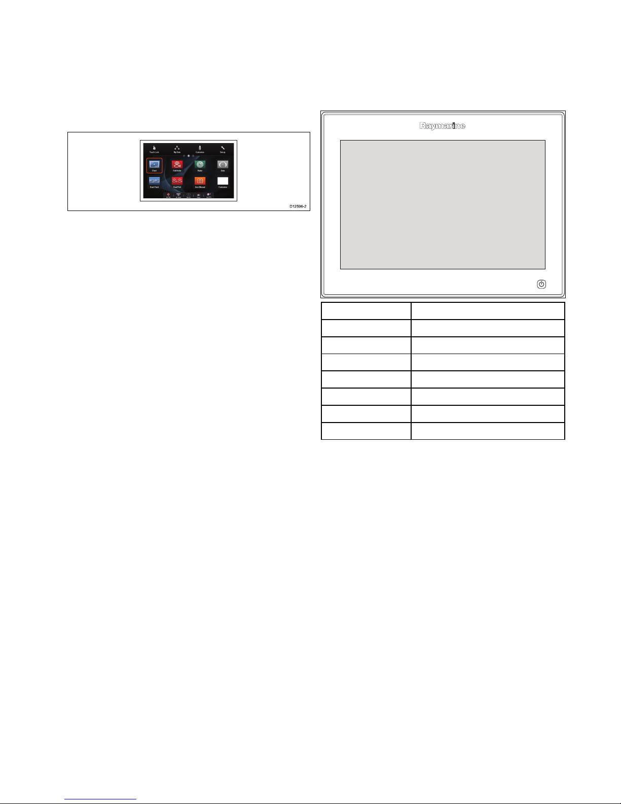
2.3Documentillustrations
Productsmaydifferslightlyfromthoseshowninthe
illustrationsinthisdocument,dependingonproduct
variantanddateofmanufacture.
Theillustrationshownbelowisusedthroughout
thisdocumenttorepresentLightHouse
TM
powered
MFDsandunlessotherwisestatedappliestoall
multifunctiondisplayvariants.
D12596-2
2.4Productoverview
Productinformation
gSSeriesMultifunctionDisplays(MFDs)are
touchscreendisplayswhichhaveHybridT ouch
functionalitywhenpairedwitharemotekeypad.The
followingRaymarineMFDvariantsareavailable.
ModelPartnumber
gS95
E70124
gS95inverted
E70183
gS125
E70125
gS125inverted
E70184
gS165
E70126
gS165inverted
E70185
gS195
E70213
RefertotheOptimumviewabilitysectionfordetails
onstandardvsinverteddisplays.
HybridTouchoverview
IfyourmultifunctiondisplayfeaturesHybridT ouch,
thisenablesyoutooperatetheunitusingthe
touchscreenandthephysicalbuttons.
AHybridT ouchdisplayhasphysicalbuttons
whichcanbeusedinadditiontothetouchscreen.
Touchscreenonlymultifunctiondisplays(which
donothavephysicalbuttons)canbeconnected
toaremotekeypadwhichallowsHybridTouch
functionality.
Allfunctionscanbeaccessedusingthetouchscreen.
However,theremaybesituations(suchasrough
seaconditions)whenitisnotappropriatetouse
thetouchscreen.Inthesesituations,Raymarine
stronglyrecommendsthatyouactivatethetouch
lockandusethephysicalbuttonstooperateyour
multifunctiondisplay .
Documentandproductinformation
13
Page 14

14
gSSeriesinstallationinstructions
Page 15

Chapter3:Planningtheinstallation
Chaptercontents
•3.1Systemintegrationonpage16
•3.2Installationchecklistonpage22
•3.3Multipledatasources(MDS)overviewonpage22
•3.4Identifyingyourdisplayvariantonpage23
•3.5Networkingconstraintsonpage23
•3.6Systemprotocolsonpage24
•3.7Datamasteronpage25
•3.8Partssuppliedonpage26
•3.9T oolsrequiredforinstallationonpage27
•3.10Selectingalocationonpage27
Planningtheinstallation
15
Page 16

3.1Systemintegration
Raymarine
®
multifunctiondisplays(MFDs)arecompatiblewithawiderangeofmarineelectronicsdevices.
1 2 8
5 6
73
16
109 11 12 13 15
4
1817
19
20
21 22
23
24
D13330-1
14
0
0
0
0
0
AUDIO
0
0
ANTENNA
NETWORK
0
POWER
0
0
00
TackTrue/AppDisplay VMG
00
INTCM
MFDsusevariousprotocolstotransferdatabetweendevicesinyoursystem.Thetablebelowdetailswhich
devicesmaybeconnectedtoyourMFD,andthetypeofconnections(intermsofprotocolsandphysical
interfaces):
ItemDeviceTypeMaximumquantitySuitableDevicesConnections
1Remotecontrol1perMFDRaymarine
®
RCU-3
Bluetooth
2Mobiledevice
(Smartphone/Tablet)
1permultifunction
display.
ForRaymarine
®
wirelessvideo
streamingandremotecontrol
apps:
•AppleiPhone4(orlater)oriPad
2(orlater)
•Androiddevicewithminimum
1GHzprocessorandrunning
android2.2.2(orlater)
•AmazonKindleFire
Forchartplottersyncwith
NavionicsMarineapp:
•AppleiPhoneoriPad
•Android-compatiblesmartphone
ortablet
Formediaplayercontrol
(TouchscreenMFDsonly):
•AnyBluetooth-enableddevice
thatsupportsBluetooth2.1+
EDRpowerclass1.5(supported
prole:AVRCP1.0)
•Chartplottersyncwith
NavionicsMarineapp:Wi-Fi
•Videostreamingandremote
control:Wi-Fi
•Mediaplayercontrol:Bluetooth
2.1+EDRpowerclass1.5
(supportedprole:AVRCP1.0)
orlater
16
gSSeriesinstallationinstructions
Page 17

ItemDeviceTypeMaximumquantitySuitableDevicesConnections
3Vesseltanksensors
—third-party
•Upto5xfuel.
•1xfreshwater.
•1xwastewater.
•1xsewage.
•1xbait/sh.
Third-partyNMEA2000interfacesNMEA2000(viaoptional
DeviceNetadaptorcables)
4
GNSSReceiver
(external)—
Raymarine
®
1
Anycombinationofthefollowing:
•RS130GPS
•Raystar125GPS
•Raystar125+GPS(viaoptional
SeaTalktoSeaTalk
ng®
converter)
SeaTalk,SeaT alk
ng®
,orNMEA
0183
5
Instruments—
Raymarine
®
Asdeterminedby
SeaTalk
ng®
bus
bandwidthandpower
loading.
SeaTalk
ng®
:
•i50Depth,Speed,orTridata
•i60Wind,CHWind
•i70
•ST70+
•ST70
SeaTalk(viaoptionalSeaTalkto
SeaTalk
ng®
converter):
•i40Wind,Speed,Depth,or
Bidata
•ST60+Wind,Speed,Depth,
Rudder,orCompass
•ST40Wind,Speed,Depth,
Rudder,orCompass
SeaTalk,SeaTalk
ng®
6Pilotcontrolheads—
Raymarine
®
Asdetermined
bySeaTalkor
SeaTalk
ng®
bus
bandwidthand
powerloading,as
appropriate.
SeaTalk
ng®
:
•p70
•p70R
•ST70(SeaTalk
ng®
course
computeronly.)
•ST70+(SeaTalk
ng®
course
computeronly.)
SeaTalk(viaoptionalSeaTalkto
SeaTalk
ng®
converter):
•ST6002
•ST7002
•ST8002
SeaTalk,SeaTalk
ng®
7
Autopilots—
Raymarine
®
1
SeaTalk
ng®
:
•Evolutionautopilots
•AllSPXcoursecomputers
SeaTalk(viaoptionalSeaTalkto
SeaTalk
ng®
converter):
•ST1000
•ST2000
•S1000
•S1
SeaTalk,SeaT alk
ng®
,orNMEA
0183
Planningtheinstallation
17
Page 18

ItemDeviceTypeMaximumquantitySuitableDevicesConnections
•S2
•S3
8
AIS—Raymarine
®
1
•AIS350
•AIS650
•AIS950
SeaTalk
ng®
,orNMEA0183
8
AIS—third-party
1Third-partyNMEA
0183–compatibleAISClass
AorClassBreceiver/transceiver
NMEA0183
9Vesseltrimtabs—
third-party
1pair
Third-partyNMEA2000interfacesNMEA2000(viaoptional
DeviceNetadaptorcables)
10
Analogvideo/cameraa6x/a7x=0
a9x/a12x/e7/e7D
=1
cSeries=1
e9x/e12x/e165=2
eSSeries=1
gSSeries=2
CompositePALorNTSCvideo
source
BNCconnectors
10IPcameraMultiple
•CAM200IP
Note:Whilstthird-party
ONVIFcompatibleIPcameras
maywork,Raymarine
®
cannot
guaranteetheircompatibility.
ViaSeaTalk
hs
network
11
Lifetag(Man
overboardalert)
1basestation
AllRaymarine
®
Lifetag
basestations
SeaTalk(viaoptionalSeaTalkto
SeaTalk
ng®
converter)
12
Engineinterface—
Raymarine
®
1unitforeachengine
CANbus
•ECI-100SeaTalk
ng®
12
Engineinterface—
third-party
1
Third-partyNMEA2000interfacesNMEA2000(viaoptional
DeviceNetadaptorcables)
13Transducers
andsensors—
Raymarine
®
1Analogtransducers:
•Wind
•Speed
•Depth
•Rudderreference
•Fluxgatecompass
SeaTalk
ng®
(viaoptionaliTC-5
converter)
13Transducersand
sensors—Airmar
1
•DT800SmartSensor
•DST800SmartSensor
•PB200weatherstation
SeaTalk
ng®
(viaoptionaliTC-5
converter)
14Externaldisplay
a6x/a7x=0
a9x/a12x=1
cSeries=0
e7/e7D=0
e9x/e12x/e165=1
eS7x=0
eS9x/eS12x=1
gSSeries=1
e.g.HDTV
a9x/a12x=15pinD-Type
connector(VGAStyle)
e9x/e12x/e165=15pinD-Type
connector(VGAStyle)
eS9x/eS12x=HDMI
gSSeries=HDMI
18
gSSeriesinstallationinstructions
Page 19

ItemDeviceTypeMaximumquantitySuitableDevicesConnections
15
Sonartransducer
1•P48
•P58
•P74
•B6020º
•B6012º
•B744V
;OR:
•Any600watt/1Kwcompatible
transducer(viaoptionalE66066
adaptorcable)
;OR:
•AnyMinnKotatransducer(via
optionalA62363adaptorcable)
Connectionviaexternal
Raymarine
®
SonarModule:
•Anysonarmodule-compatible
transducer
Directconnectionto600W
internalsonarvariantdisplays.
15DownVision
™
transducers
1Directconnectiontointernal
CHIRPDownVision
TM
variant
displays
•CPT-100—Transommount
•CPT-110—Thru-hullplastic
•CPT-120—Thru-hullbronze
DirectconnectiontoCHIRP
DownVision
™
variantdisplays.
16
DSCVHFradio—
Raymarine
®
1
SeaTalk
ng®
:
•Ray50
•Ray60
•Ray70
•Ray260
•Ray260AIS
NMEA0183:
•Ray50
•Ray60
•Ray70
•Ray49
•Ray55
•Ray218
•Ray240
NMEA0183orSeaTalk
ng®
17
Raymarine
®
Sirius
marineweather/
satelliteradioreceiver
(NorthAmericaonly)
1
SeaTalk
hs
:
•SR150
•SR100
•SR6
SeaTalk
ng®
:
•SR50
SeaTalk
hs
,SeaTalk
ng®
Planningtheinstallation
19
Page 20

ItemDeviceTypeMaximumquantitySuitableDevicesConnections
18Additional
multifunction
display(s)—
Raymarine
®
93rdgenerationRaymarine
®
multifunctiondisplays
SeaTalk
hs
(recommended):
•aSeries
•cSeries
•eSeries
•gSSeries
•eSSeries
Note:Youcanconnect
Raymarine
®
multifunction
displaysusingNMEA0183or
SeaTalk
ng®
butnotallfunctions
aresupported.
Note:Visit
www.raymarine.comto
downloadthelatestsoftware
versionforyourdisplay.
SeaTalk
hs
18Additional
multifunction
display(s)—
third-party
•Connectionsto
multifunction
displayNMEA
outputs:4
•Connectionsto
multifunction
displayNMEA
inputs:2
NMEA0183–compatible
chartplottersandmultifunction
displays
NMEA0183
19
SonarModules
(Fishnder)—
Raymarine
®
Multiple
•CP100—DownVision
™
•CP200—SideVision
™
•CP300/CP370—Traditional
sonar
•CP450C/CP470—CHIRP
sonar
•CP570CHIRPprofessional
sonar
•600WSonarandCHIRP
DownVision
™
variantdisplays.
SeaTalk
hs
20Radar—Raymarine
®
2AllRaymarine
®
Non-HDDigital
RadomesandHDorSuperHD
radarscanners.
Note:Pleaseensureyour
radarscannerisusingthelatest
softwareversion.
SeaTalk
hs
21Thermalcamera—
Raymarine
®
1
•T200Series
•T300Series
•T400Series
•T800Series
•T900Series
SeaTalk
hs
(forcontrol),BNC
connector(forvideo)
22RemotekeypadMultiple•RMK-9
SeaTalk
hs
20
gSSeriesinstallationinstructions
Page 21

ItemDeviceTypeMaximumquantitySuitableDevicesConnections
23Fusionentertainment
systems
MultipleFusion700seriesentertainment
systems:
•MS-IP700
•MS-AV700
SeaTalk
hs
24
PC/laptop
1
Windows-compatiblePCorlaptop
runningRaymarine
®
Voyage
Plannersoftware.
SeaTalk
hs
Note:Raymarine
®
cannotguaranteethecompatibilityofanythird-partydeviceslistedabove.
Planningtheinstallation
21
Page 22

3.2Installationchecklist
Installationincludesthefollowingactivities:
InstallationTask
1Planyoursystem.
2
Obtainallrequiredequipmentandtools.
3
Siteallequipment.
4Routeallcables.
5
Drillcableandmountingholes.
6Makeallconnectionsintoequipment.
7
Secureallequipmentinplace.
8Poweronandtestthesystem.
3.3Multipledatasources(MDS)
overview
Installationsthatincludemultipleinstancesofdata
sourcescancausedataconicts.Anexampleisan
installationfeaturingmorethanonesourceofGPS
data.
MDSenablesyoutomanageconictsinvolvingthe
followingtypesofdata:
•GPSPosition.
•Heading.
•Depth.
•Speed.
•Wind.
Typicallythisexerciseiscompletedaspartofthe
initialinstallation,orwhennewequipmentisadded.
IfthisexerciseisNOTcompletedthesystemwill
automaticallyattempttoresolvedataconicts.
However,thismayresultinthesystemchoosinga
sourceofdatathatyoudonotwanttouse.
IfMDSisavailablethesystemcanlisttheavailable
datasourcesandallowyoutoselectyourpreferred
datasource.ForMDStobeavailableallproducts
inthesystemthatusethedatasourceslisted
abovemustbeMDS-compliant.Thesystemcan
listanyproductsthatareNOTcompliant.Itmay
benecessarytoupgradethesoftwareforthese
non-compliantproductstomakethemcompliant.
VisittheRaymarinewebsite(www.raymarine.com)
toobtainthelatestsoftwareforyourproducts.If
MDS-compliantsoftwareisnotavailableandyoudo
NOTwantthesystemtoautomaticallyattemptto
resolvedataconicts,anynon-compliantproduct(s)
canberemovedorreplacedtoensuretheentire
systemisMDS-compliant.
22
gSSeriesinstallationinstructions
Page 23

3.4Identifyingyourdisplayvariant
Todiscoverwhichmodeldisplayyouhavefollowthe
stepsbelow:
Fromthehomescreen:
1.SelectSet-up.
2.SelectMaintenance.
3.SelectDiagnostics.
4.SelectSelectDevice.
5.SearchtheNetworkcolumnforthe'ThisDevice'
entry.
6.TheDevicecolumnforthisrecordwilllistthe
modelofyourdisplay.
3.5Networkingconstraints
Upto10LightHousepoweredMFDscan
beconnectedtogetherusingSeaTalk
hs
.Itis
recommendedthatallnetworkeddisplayscontain
thesamesoftwareversion.
Softwareversions
•AllnetworkedaaSeries,cSeriesandeSeries
displaysmustcontainLightHousesoftware
releaseV4.32orlater.
•AllnetworkedgSSeriesdisplaysmustcontain
LightHousesoftwarereleaseV7.43orlater.
•AllnetworkedeSSeriesdisplaysmustcontain
LightHousesoftwarereleaseV14.xxorlater.
Master/repeateroperation
•Anynetworkfeaturingmorethan1MFDmusthave
1ofthedisplaysdesignatedastheDataMaster.
•TheDataMasterdisplaywillreceivedatathrough
NMEA0183and/orSeaTalk
ng®
,andbridgethe
dataoverSeaTalk
hs
toothernetworkeddisplays.
Homescreensharing
•Whennetworked,MFDscansharetheData
Master’sHomescreen.
Cartographysharing
•Thecartographycontainedonchartcardsis
alwaysusedinpreferencetoembeddedworld
basemaps.
•Chartcardcartographycanbesharedbetween
networkedMFDs.
Radaroperation
•MFDssupporttheuseofupto2Radarscanners
simultaneously.
•ThedatasuppliedbyaconnectedRadar
scanner(s)isrepeatedtonetworkeddisplays.
Note:AllMFDsmusthaveLightHouseIIRelease
V12.26softwareorlatertoenablemultipleradar
support.
Sonar/DownVision
™
/SideVision
™
operation
•Y oucanconnectanexternalsonarmodulestothe
MFDviatheSeaTalk
hs
network.
•600WsonarandCHIRPDownVision
™
variant
displaysincludeaninternalsonarmodulewhich
enablesdirectconnectionofacompatible
transducer.
•Y oucanhavemultipleactivesonarmodules
(internalandexternal)onanetwork.
•Thedatasuppliedbythesonarmoduleisrepeated
tonetworkeddisplays.
Planningtheinstallation
23
Page 24

Note:
•AllMFDsmusthaveLightHouseIIRelease
V10.41softwareorlatertoenablemultiplesonar
support.
•Sonarmodulesshouldbeupdatedtothe
latestavailablesoftwareversiontoensure
compatibility.
Incompatibledisplays
Ifyouconnectamultifunctiondisplaytoyoursystem
thatisnotcompatible,awarningmessagewillbe
displayeduntilyoudisconnecttheincompatible
devicefromyournetwork.
YourMFDisnotcompatiblewiththefollowing
Raymarinedisplays:
ProductImage
Multifunction
displayGeneration
G-Series
2ndgeneration
E-Series
Widescreen
2ndgeneration
C-Series
Widescreen
2ndgeneration
PAGE
ACTIVE
WPTS
MOB
MENU
DATA
CANCELOK
RANGE
IN
OUT
E-SeriesClassic
1stgeneration
PAGE
ACTIVE
WPTS
MOB
MENU
DATA
CANCELOK
RANGE
IN
OUT
C-SeriesClassic
1stgeneration
3.6Systemprotocols
YourMultifunctionDisplaycanconnecttovarious
instrumentsanddisplaystoshareinformationand
soimprovethefunctionalityofthesystem.These
connectionsmaybemadeusinganumberof
differentprotocols.Fastandaccuratedatacollection
andtransferisachievedbyusingacombinationof
thefollowingdataprotocols:
•SeaT alk
hs
•SeaT alk
ng
•NMEA2000
•SeaT alk
•NMEA0183
Note:Y oumayndthatyoursystemdoesnot
usealloftheconnectiontypesorinstrumentation
describedinthissection.
SeaTalk
hs
SeaTalk
hs
isanethernetbasedmarinenetwork.This
highspeedprotocolallowscompatibleequipment
tocommunicaterapidlyandsharelargeamountsof
data.
InformationsharedusingtheSeaTalk
hs
network
includes:
•Sharedcartography(betweencompatible
displays).
•Digitalradardata.
•Sonardata.
Seatalk
ng
SeaTalk
ng
(NextGeneration)isanenhancedprotocol
forconnectionofcompatiblemarineinstruments
andequipment.ItreplacestheolderSeaT alkand
SeaTalk
2
protocols.
SeaTalk
ng
utilizesasinglebackbonetowhich
compatibleinstrumentsconnectusingaspur.Data
andpowerarecarriedwithinthebackbone.Devices
thathavealowdrawcanbepoweredfromthe
network,althoughhighcurrentequipmentwillneed
tohaveaseparatepowerconnection.
SeaTalk
ng
isaproprietaryextensiontoNMEA2000
andtheprovenCANbustechnology.Compatible
NMEA2000andSeaTalk/SeaTalk
2
devicescan
alsobeconnectedusingtheappropriateinterfaces
oradaptorcablesasrequired.
NMEA2000
NMEA2000offerssignicantimprovementsover
NMEA0183,mostnotablyinspeedandconnectivity.
Upto50unitscansimultaneouslytransmitand
receiveonasinglephysicalbusatanyonetime,
witheachnodebeingphysicallyaddressable.The
standardwasspecicallyintendedtoallowfor
24
gSSeriesinstallationinstructions
Page 25

awholenetworkofmarineelectronicsfromany
manufacturertocommunicateonacommonbusvia
standardizedmessagetypesandformats.
SeaTalk
SeaTalkisaprotocolwhichenablescompatible
instrumentstoconnecttoeachotherandsharedata.
TheSeaT alkcablesystemisusedtoconnect
compatibleinstrumentsandequipment.Thecable
carriespoweranddataandenablesconnection
withouttheneedforacentralprocessor.
Additionalinstrumentsandfunctionscanbeaddedto
aSeaTalksystem,simplybypluggingthemintothe
network.SeaTalkequipmentcanalsocommunicate
withothernon-SeaT alkequipmentviatheNMEA
0183standard,providedasuitableinterfaceisused.
NMEA0183
TheNMEA0183DataInterfaceStandardwas
developedbytheNationalMarineElectronics
AssociationofAmerica.Itisaninternational
standardtoenableequipmentfrommanydifferent
manufacturerstobeconnectedtogetherandshare
information.
TheNMEA0183standardcarriessimilarinformation
toSeaTalk.Howeverithastheimportantdifference
thatonecablewillonlycarryinformationinone
direction.ForthisreasonNMEA0183isgenerally
usedtoconnectadatareceiverandatransmitter
together,e.g.acompasssensortransmitting
headingtoaradardisplay.Thisinformationis
passedin‘sentences’,eachofwhichhasathree
lettersentenceidentier.Itisthereforeimportant
whencheckingcompatibilitybetweenitemsthatthe
samesentenceidentiersareusedsomeexamples
ofwhichare:
•VTG-carriesCourseandSpeedOverGround
data.
•GLL-carrieslatitudeandlongitude.
•DBT-carrieswaterdepth.
•MWV-carriesrelativewindangleandwindspeed
data.
NMEABaudrates
TheNMEA0183standardoperatesatanumber
ofdifferentspeeds,dependingupontheparticular
requirementorequipmentcapabilities.Typical
examplesare:
•4800baudrate.Usedforgeneralpurpose
communications,includingFastHeadingdata.
•38400baudrate.UsedforAISandotherhigh
speedapplications.
3.7Datamaster
Anysystemcontainingmorethanonenetworked
multifunctiondisplaymusthaveadesignateddata
master.
Thedatamasteristhedisplaywhichservesasa
primarysourceofdataforalldisplays,italsohandles
allexternalsourcesofinformation.Forexample
thedisplaysmayrequireheadinginformationfrom
theautopilotandGPSsystems,usuallyreceived
throughaSeaTalk
ng
orNMEAconnection.Thedata
masteristhedisplaytowhichtheSeaTalk,NMEA
andanyotherdataconnectionsaremade,itthen
bridgesthedatatotheSeaT alk
hs
networkandany
compatiblerepeatdisplays.Informationsharedby
thedatamasterincludes:
•Cartography
•Routesandwaypoints
•Radar
•Sonar
•Datareceivedfromtheautopilot,instruments,the
engineandotherexternalsources.
Yoursystemmaybewiredforredundancywithdata
connectionsmadetorepeatdisplays.Howeverthese
connectionswillonlybecomeactiveintheeventofa
faultand/orreassignmentofthedatamaster.
Inanautopilotsystemwhichdoesnotcontaina
dedicatedpilotcontrolheadtheDatamasteralso
actsasthecontrolfortheautopilot.
Planningtheinstallation
25
Page 26

3.8Partssupplied
Thefollowingpartsaresuppliedwithyourproduct.
1 2
8
13
14
16
17
18
9 10
12
11
3
4 5
6
7
15
x4
x2
x4 x4
D12886-2
1
Multifunctiondisplay
22xDisplaymountingbrackets
3
RCR-2RemoteCardReader
4
MountinggasketforRCR-2
5
Documentpack
6
RCR-2inlaycardx2
7
Suncover
8
4xMountingbolts,washers,locknutsandfeet
9
4xBracketxings
•gS95=M5x25panhead
•gS125andgS165=M5x25countersunk
•gS195=M5x60countersunk
10
4xRCR-2xings(self-tappingscrews)
11
M5x10panheadscrew(notsuppliedwithgS95)
12
M5Wavywasher(foradditionalgroundingstrap)
13
1.5m(4.9ft)Power/Datacable
14
2m(6.6ft)Video/Alarmcable
15Displaymountinggasket
16
2m(6.6ft)RayNetcable
17Auxiliaryalarm
18
1m(3.28ft)SeaT alk
ng
spurcable
HD-SDIadditionalpartssupplied
ThegS195issuppliedwiththefollowingadditional
partsforusewiththeHD-SDIconnection.
D13051-2
1 2 3
1Protectiveboot
2
75ohmBNCconnector
4
Cabletiesx2(tosecuretheprotectiveboot)
26
gSSeriesinstallationinstructions
Page 27

3.9Toolsrequiredforinstallation
D12171-2
1
4
5
3
876
2
1.Powerdrill.
2.Jigsaw.
3.Pozidrivescrewdriver.
4.Adhesivetape.
5.Spannerforsurfacemountingorbracket
mountingxings.
6.File.
7.Holesawforushmounting(Forholesawsize
refertoyourproduct’smountingtemplate).
8.Drillbitforsurfacemountingorushmounting.
AdditionaltoolsforFlushmounting
Forbestresultswhenushmountingthedisplays
itisrecommendedthatarouterisusedtocutout
therebate.
3.10Selectingalocation
Warning:Potentialignitionsource
ThisproductisNOTapprovedforusein
hazardous/ammableatmospheres.Do
NOTinstallinahazardous/ammable
atmosphere(suchasinanengineroom
ornearfueltanks).
Generallocationrequirements
Whenselectingalocationforyourproductitis
importanttoconsideranumberoffactors.
Keyfactorswhichcanaffectproductperformance
are:
•Ventilation
Toensureadequateairow:
–Ensurethatproductismountedina
compartmentofsuitablesize.
–Ensurethatventilationholesarenotobstructed.
Allowadequateseparationofallequipment.
Anyspecicrequirementsforeachsystem
componentareprovidedlaterinthischapter.
•Mountingsurface
Ensureproductisadequatelysupportedona
securesurface.Donotmountunitsorcutholes
inplaceswhichmaydamagethestructureofthe
vessel.
•Cabling
Ensuretheproductismountedinalocationwhich
allowsproperrouting,supportandconnectionof
cables:
–Minimumbendradiusof100mm(3.94in)
unlessotherwisestated.
–Usecableclipstopreventstressonconnectors.
–Ifyourinstallationrequiresmultipleferritesto
beaddedtoacablethenadditionalcableclips
shouldbeusedtoensuretheextraweightof
thecableissupported.
•Wateringress
Theproductissuitableformountingbothabove
andbelowdecks.Althoughtheunitiswaterproof,
itisgoodpracticetolocateitinaprotectedarea
awayfromprolongedanddirectexposuretorain
andsaltspray.
•Electricalinterference
Selectalocationthatisfarenoughawayfrom
devicesthatmaycauseinterference,suchas
motors,generatorsandradiotransmitters/
receivers.
•Powersupply
Selectalocationthatisascloseaspossibletothe
vessel’sDCpowersource.Thiswillhelptokeep
cablerunstoaminimum.
Planningtheinstallation
27
Page 28
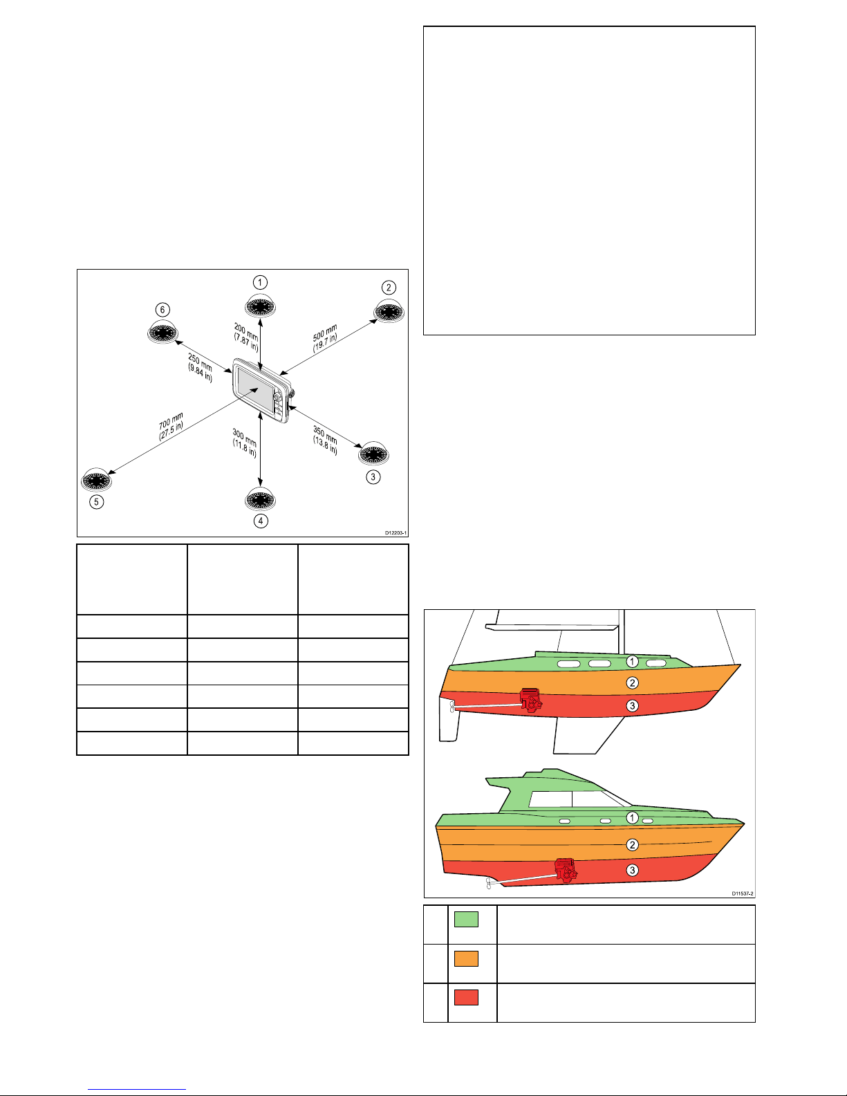
Compasssafedistance
Topreventpotentialinterferencewiththevessel's
magneticcompasses,ensureanadequatedistance
ismaintainedfromthedisplay.
Whenchoosingasuitablelocationforthe
multifunctiondisplayyoushouldaimtomaintainthe
maximumpossibledistancebetweenthedisplayand
anycompasses.Typicallythisdistanceshouldbeat
least1m(3ft)inalldirections.Howeverforsome
smallervesselsitmaynotbepossibletolocate
thedisplaythisfarawayfromacompass.Inthis
situation,thefollowingguresprovidetheminimum
safedistancethatshouldbemaintainedbetweenthe
displayandanycompasses.
D1220 3-1
200 mm
(7.87 in)
350 mm
(13.8 in)
300 mm
(11.8 in
)
700 mm
(27.5 in)
500 mm
(19.7 in)
250 mm
(9.84 in)
1
2
3
4
5
6
Item
Compass
positionin
relationto
display
Minimumsafe
distancefrom
display
1Top
200mm(7.87in.)
2Rear
500mm(19.7in.)
3Right-handside
350mm(13.8in.)
4Underside
300mm(11.8in.)
5
Front
700mm(27.5in.)
6
Left-handside250mm(9.84in.)
Caution:Mountingsurface
requirements
Thisproductisheavy.T opreventpotential
damagetotheproductand/oryour
vessel,observethefollowingBEFORE
installingtheproduct:
•Refertotheweightinformationprovided
inthetechnicalspecicationforthis
productandensurethattheintended
mountingsurfaceissuitableforbearing
theweight.
•Ifthemountingsurfaceisnotsuitable
fortheproductweight,youmayneedto
reinforcethemountingsurface.
•Ifindoubt,refertoaprofessional
marineequipmentinstallerforfurther
guidance.
GPSlocationrequirements
Inadditiontogeneralguidelinesconcerningthe
locationofmarineelectronics,thereareanumber
ofenvironmentalfactorstoconsiderwheninstalling
equipmentwithaninternalGPSantenna.
Mountinglocation
•AboveDecksmounting:
ProvidesoptimalGPSperformance.(For
equipmentwithappropriatewaterproofrating.)
•BelowDecksmounting:
GPSperformancemaybelesseffectiveandmay
requireanexternalGPSantennamountedabove
decks.
D11537 -2
1
2
3
1
2
3
1.
ThislocationprovidesoptimalGPS
performance(abovedecks).
2.
Inthislocation,GPSperformancemaybeless
effective.
3.
ThislocationisNOTrecommendedforGPS
antenna.
28
gSSeriesinstallationinstructions
Page 29

Vesselconstruction
Theconstructionofyourvesselcanhaveanimpact
onGPSperformance.Forexample,theproximity
ofheavystructuresuchasastructuralbulkhead,
ortheinterioroflargervesselsmayresultina
reducedGPSsignal.Beforelocatingequipment
withaninternalGPSantennabelowdecks,seek
professionalassistanceandconsideruseofan
externalGPSantennamountedabovedecks.
Prevailingconditions
Theweatherandlocationofthevesselcanaffectthe
GPSperformance.Typicallycalmclearconditions
provideforamoreaccurateGPSx.Vesselsat
extremenortherlyorsoutherlylatitudesmayalso
receiveaweakerGPSsignal.GPSantennamounted
belowdeckswillbemoresusceptibletoperformance
issuesrelatedtotheprevailingconditions.
EMCinstallationguidelines
Raymarineequipmentandaccessoriesconformto
theappropriateElectromagneticCompatibility(EMC)
regulations,tominimizeelectromagneticinterference
betweenequipmentandminimizetheeffectsuch
interferencecouldhaveontheperformanceofyour
system
CorrectinstallationisrequiredtoensurethatEMC
performanceisnotcompromised.
Note:InareasofextremeEMCinterference,
someslightinterferencemaybenoticedonthe
product.Wherethisoccurstheproductandthe
sourceoftheinterferenceshouldbeseparatedby
agreaterdistance.
ForoptimumEMCperformancewerecommend
thatwhereverpossible:
•Raymarineequipmentandcablesconnectedto
itare:
–Atleast1m(3ft)fromanyequipment
transmittingorcablescarryingradiosignalse.g.
VHFradios,cablesandantennas.Inthecase
ofSSBradios,thedistanceshouldbeincreased
to7ft(2m).
–Morethan2m(7ft)fromthepathofaradar
beam.Aradarbeamcannormallybeassumed
tospread20degreesaboveandbelowthe
radiatingelement.
•Theproductissuppliedfromaseparatebattery
fromthatusedforenginestart.Thisisimportantto
preventerraticbehavioranddatalosswhichcan
occuriftheenginestartdoesnothaveaseparate
battery.
•Raymarinespeciedcablesareused.
•Cablesarenotcutorextended,unlessdoingsois
detailedintheinstallationmanual.
Note:Whereconstraintsontheinstallation
preventanyoftheaboverecommendations,
alwaysensurethemaximumpossibleseparation
betweendifferentitemsofelectricalequipment,to
providethebestconditionsforEMCperformance
throughouttheinstallation
Viewingangleconsiderations
Asdisplaycontrast,colorandnightmode
performanceareallaffectedbytheviewingangle,
Raymarinerecommendsyoutemporarilypowerup
thedisplaywhenplanningtheinstallation,toenable
youtobestjudgewhichlocationgivestheoptimum
viewingangle.
LCDorientation
Raymarinemultifunctiondisplays(MFDs)canbe
viewedfromwideanglestoptobottomandleftto
right.
3
4
2
1
D13119-1
1.Top
2.Bottom
3.Left
4.Right
LCDscanbeorientatedin2directions:
1 2
D13120-1
1.12O’clock—Standardorientation(Inthe12
O’clockorientationtheLCDisbetterviewedfrom
toptobottomthanitisfrombottomtotop.)
2.6O’clock—Invertedorientation(Inthe6
O’clockorientationtheLCDisbetterviewedfrom
bottomtotopthanitisfromtoptobottom.)
ThetablebelowdetailstheLCDorientationforeach
gSSeriesMFD.
MFD
LCD
orientationMFD
LCD
orientation
gS95
(E70124)
12O’clockgS95INV
(E70183)
6O’clock
gS125
(E70125)
12O’clockgS125INV
(E70184)
6O’clock
Planningtheinstallation
29
Page 30

MFD
LCD
orientationMFD
LCD
orientation
gS165
(E70126)
12O’clockgS165INV
(E70185)
6O’clock
gS195
(E70213)
6O’clock
Productdimensions
A C
D E
B
D12716-2
gS95gS125gS165gS195
A246.8mm
(9.7in)
311.8mm
(12.3in)
383.2mm
(15in)
433.9mm
(17.1in)
B188.2mm
(7.4in)
237.1mm
(9.3in)
284.7mm
(11.2in)
391.2mm
(15.4in)
C
8mm
(0.31in)
8mm
(0.31in)
8mm
(0.31in)
8mm
(0.31in)
D69mm
(2.72in)
70mm
(2.75in)
69mm
(2.72in)
75.9mm
(3in)
E114.1mm
(7.8in)
114.1mm
(7.8in)
114.1mm
(7.8in)
114.1mm
(7.8in)
Cardreaderdimensions
A C D F
B
E
D12725-1
A
55mm(2.17in)
B
55mm(2.17in)
C8.5mm(0.33in)
D
36mm(1.4in)
E
39.2mm(1.5in)
F
90mm(3.5in)
30
gSSeriesinstallationinstructions
Page 31

Chapter4:Cablesandconnections
Chaptercontents
•4.1Generalcablingguidanceonpage32
•4.2gS95/gS125/gS165Connectionsoverviewonpage33
•4.3gS195connectionsoverviewonpage33
•4.4Poweranddata(combined)connectiononpage34
•4.5PoweroverEthernet(PoE)onpage36
•4.6Cardreaderconnectiononpage36
•4.7Auxiliaryalarmconnectiononpage37
•4.8SeaT alk
ng®
connectionsonpage37
•4.9NMEA2000connectiononpage38
•4.10SeaT alkconnectiononpage39
•4.11NMEA0183connection—Power/NMEA/Videocableonpage39
•4.12Gigabitnetworkingonpage40
•4.13Sonarmoduleconnectiononpage41
•4.14Radarnetworkconnectiononpage42
•4.15GNSS/GPSconnectiononpage44
•4.16AISconnectiononpage45
•4.17Fastheadingconnectiononpage45
•4.18Keypadnetworkconnectiononpage46
•4.19Weatherreceiverconnectiononpage46
•4.20Videoconnection—compositeonpage47
•4.21Camera(Video/Alarm)connectiononpage47
•4.22HDMIvideooutputonpage48
•4.23IPCameraconnectiononpage48
•4.24HD-SDIconnection(gS195)onpage49
•4.25Thermalcameraconnectiononpage50
•4.26Fusionnetworkconnectiononpage52
•4.27FusionNMEA2000connectiononpage52
•4.28Mediaplayerconnectiononpage53
•4.29Raymarinemobileappconnectiononpage53
•4.30Bluetoothremotecontrolconnectiononpage54
Cablesandconnections31
Page 32

4.1Generalcablingguidance
Suppressionferrites
Raymarinecablesmaybettedwithsuppression
ferrites.TheseareimportantforcorrectEMC
performance.Ifaferritehastoberemovedforany
purpose(e.g.installationormaintenance),itmustbe
replacedintheoriginalpositionbeforetheproduct
isused.
Useonlyferritesofthecorrecttype,suppliedby
Raymarineauthorizeddealers.
Whereaninstallationrequiresmultipleferritestobe
addedtoacable,additionalcableclipsshouldbe
usedtopreventstressontheconnectorsduetothe
extraweightofthecable.
Connectionstootherequipment
Requirementforferritesonnon-Raymarinecables
IfyourRaymarineequipmentistobeconnected
tootherequipmentusingacablenotsuppliedby
Raymarine,asuppressionferriteMUSTalwaysbe
attachedtothecableneartheRaymarineunit.
Cabletypesandlength
Itisimportanttousecablesoftheappropriatetype
andlength
•Unlessotherwisestateduseonlystandardcables
ofthecorrecttype,suppliedbyRaymarine.
•Ensurethatanynon-Raymarinecablesareofthe
correctqualityandgauge.Forexample,longer
powercablerunsmayrequirelargerwiregauges
tominimizevoltagedropalongtherun.
Routingcables
Cablesmustberoutedcorrectly,tomaximize
performanceandprolongcablelife.
•DoNOTbendcablesexcessively.Wherever
possible,ensureaminimumbenddiameterof200
mm(8in)/minimumbendradiusof100mm(4in).
100 mm (4 in)
200 mm (8 in)
•Protectallcablesfromphysicaldamageand
exposuretoheat.Usetrunkingorconduitwhere
possible.DoNOTruncablesthroughbilgesor
doorways,orclosetomovingorhotobjects.
•Securecablesinplaceusingtie-wrapsorlacing
twine.Coilanyextracableandtieitoutoftheway.
•Whereacablepassesthroughanexposed
bulkheadordeckhead,useasuitablewatertight
feed-through.
•DoNOTruncablesneartoenginesoruorescent
lights.
Alwaysroutedatacablesasfarawayaspossible
from:
•otherequipmentandcables,
•highcurrentcarryingacanddcpowerlines,
•antennae.
Strainrelief
Ensureadequatestrainreliefisprovided.Protect
connectorsfromstrainandensuretheywillnotpull
outunderextremeseaconditions.
Circuitisolation
Appropriatecircuitisolationisrequiredfor
installationsusingbothACandDCcurrent:
•Alwaysuseisolatingtransformersoraseparate
power-invertertorunPC’s,processors,displays
andothersensitiveelectronicinstrumentsor
devices.
•AlwaysuseanisolatingtransformerwithWeather
FAXaudiocables.
•Alwaysuseanisolatedpowersupplywhenusing
a3rdpartyaudioamplier.
•AlwaysuseanRS232/NMEAconverterwith
opticalisolationonthesignallines.
•AlwaysmakesurethatPC’sorothersensitive
electronicdeviceshaveadedicatedpowercircuit.
Cableshielding
Ensurethatalldatacablesareproperlyshielded
thatthecableshieldingisintact(e.g.hasn’tbeen
scrapedoffbybeingsqueezedthroughatightarea).
Networkcableconnectortypes
Thereare2typesofnetworkcableconnector—
SeaTalk
hs
andRayNet.
SeaTalk
hs
connector—usedfor
connectingSeaTalk
hs
devicesto
aRaymarinenetworkswitchvia
SeaTalk
hs
cables.
RayNetconnector—usedfor
connectingRaymarinenetwork
switchesandSeaTalk
hs
devicesto
themultifunctiondisplayviaRayNet
cables.Alsorequiredforconnectinga
crossovercouplerifonlyonedevice
isbeingconnectedtothedisplay's
Networkconnector.
32
gSSeriesinstallationinstructions
Page 33

4.2gS95/gS125/gS165Connections
overview
Detailsoftheconnectionsavailableonthe
multifunctiondisplayareshownbelow.
D12700-1
1 2 4 5 63
1
SeaTalk
ng
2HDMI
3
3xPoE/RayNetSeaTalk
hs
4
Cardreader
5
Videoin/AlarmOut
6
Power/NMEA0183/Videoin
4.3gS195connectionsoverview
DetailsoftheconnectionsavailableonthegS195
areshownbelow.
D13044-3
7 8
1 2 3 4 5 6
1
SeaTalk
ng
connection
2
HDMIOutput
3
PoE/RayNetSeaT alk
hs
connection
4
Cardreaderconnection
5
AnaloguevideoInput/AlarmOutput
6
Power/NMEA0183/AnaloguevideoInput
7
HD-SDIVideoInput
8
PoE/RayNetSeaT alk
hs
connection
Connectorandcableprotectivecaps
Unusedconnectorsanddisconnectedcablesshould
beadequatelyprotectedagainstdamage.
Important:
Therearconnectorsonyourproductarettedwith
protectivecapswhichshouldbesecurelytted
overanyconnectorsthatarenotgoingtobeused
/connected.
Ifanycablesaretobeleftdisconnectedthen,
ifavailableusethecablesprotectivecapor
insulationtapetoprotectthecableconnector.
Cablesandconnections33
Page 34

4.4Poweranddata(combined)
connection
ThedetailsbelowapplytoMFDsthathavea
combinedpower/NMEA/videocable.
RefertotheConnectionsOverviewsectionto
establishthepowerconnectionforyourMFD.
D13283-2
2
1
4
5
7
3
8
6
9
1.MFD
2.CombinedPoweranddatacable
3.Connectiontovessel’s12V/24Vdcpower
supply
4.Redcable(positive)
5.Fuse
6.Blackcable(negative)
7.Videoinputcable
8.NMEA0183datacables
9.Ground(drain)wire
In-linefuseandthermalbreakerratings
Thefollowingin-linefuseandthermalbreakerratings
applytoyourproduct:
In-linefuseratingThermalbreakerrating
15A
15A(ifonlyconnectingone
device)
Note:
•Thesuitablefuseratingforthethermalbreaker
isdependentonthenumberofdevicesyouare
connecting.Ifindoubtconsultanauthorized
Raymarinedealer.
•Y ourproduct’spowercablemayhavetted
in-linefuse,ifnotthenyoucanaddanin-line
fusetothepositivewireofyourproductspower
connection.
Powerdistribution
Recommendationsandbestpractice.
•Theproductissuppliedwithapowercable.Only
usethepowercablesuppliedwiththeproduct.Do
NOTuseapowercabledesignedfor,orsupplied
with,adifferentproduct.
•RefertothePowerconnectionsectionformore
informationonhowtoidentifythewiresinyour
product’spowercable,andwheretoconnectthem.
•Seebelowformoreinformationonimplementation
forsomecommonpowerdistributionscenarios.
Important:Whenplanningandwiring,takeinto
considerationotherproductsinyoursystem,some
ofwhich(e.g.sonarmodules)mayplacelarge
powerdemandpeaksonthevessel’selectrical
system.
Note:Theinformationprovidedbelowisfor
guidanceonly ,tohelpprotectyourproduct.It
coverscommonvesselpowerarrangements,but
doesNOTcovereveryscenario.Ifyouareunsure
howtoprovidethecorrectlevelofprotection,
pleaseconsultanauthorizedRaymarinedealeror
asuitablyqualiedprofessionalmarineelectrician.
Implementation—directconnectiontobattery
•Thepowercablesuppliedwithyourproductmay
beconnecteddirectlytothevessel'sbattery,viaa
suitablyratedfuseorbreaker.
•Thepowercablesuppliedwithyourproductmay
NOTincludeaseparatedrainwire.Ifthisisthe
case,onlythepowercable’sredandblackwires
needtobeconnected.
•IfthesuppliedpowercableisNOTttedwithan
inlinefuse,youMUSTtasuitablyratedfuseor
breakerbetweentheredwireandthebattery’s
positiveterminal.
•Refertotheinlinefuseratingsprovidedinthe
product’sdocumentation.
•Ifyouneedtoextendthelengthofthepowercable
suppliedwithyourproduct,ensureyouobserve
thededicatedPowercableextensionsadvice
providedintheproduct’sdocumentation.
D13344-1
A
B
34
gSSeriesinstallationinstructions
Page 35

A
BatteryconnectionscenarioA:suitableforavesselwith
acommonRFgroundpoint.Inthisscenario,ifyour
product’spowercableissuppliedwithaseparatedrain
wirethenitshouldbeconnectedtothevessel’scommon
groundpoint.
B
BatteryconnectionscenarioB:suitableforavessel
withoutacommongroundingpoint.Inthiscase,ifyour
product’spowercableissuppliedwithaseparatedrain
wirethenitshouldbeconnecteddirectlytothebattery’s
negativeterminal.
Implementation—connectiontodistribution
panel
D13348-1
•Alternatively,thesuppliedpowercablemaybe
connectedtoasuitablebreakerorswitchonthe
vessel'sdistributionpanelorfactory-ttedpower
distributionpoint.
•Thedistributionpointshouldbefedfromthe
vessel’sprimarypowersourceby8AWG
(8.36mm
2
)cable.
•Ideally,allequipmentshouldbewiredtoindividual
suitably-ratedthermalbreakersorfuses,with
appropriatecircuitprotection.Wherethisisnot
possibleandmorethan1itemofequipment
sharesabreaker,useindividualin-linefuses
foreachpowercircuittoprovidethenecessary
protection.
•Inallcases,observetherecommended
breaker/fuseratingsprovidedintheproduct’s
documentation.
•Ifyouneedtoextendthelengthofthepowercable
suppliedwithyourproduct,ensureyouobserve
thededicatedPowercableextensionsadvice
providedintheproduct’sdocumentation.
Important:Beawarethatthesuitablefuserating
forthethermalbreakerorfuseisdependentonthe
numberofdevicesyouareconnecting.
Grounding
Ensurethatyouobservetheseparategrounding
adviceprovidedintheproduct’sdocumentation.
Moreinformation
Raymarinerecommendsthatbestpracticeis
observedinallvesselelectricalinstallations,as
detailedinthefollowingstandards:
•BMEACodeofPracticeforElectricaland
ElectronicInstallationsinBoats
•NMEA0400InstallationStandard
•ABYCE-11AC&DCElectricalSystemsonBoats
•ABYCA-31BatterychargersandInverters
•ABYCTE-4LightningProtection
Powercableextension
Theproductissuppliedwithapowercable,which
canbeextendedifrequired.
•Thepowercableforeachunitinyoursystem
shouldberunasaseparate,singlelengthof
2-wirecablefromtheunittothevessel'sbatteryor
distributionpanel.
•Raymarinerecommendsaminimumwiregauge
of18AWG(0.82mm
2
)foranylengthofcable
extension.
•Foralllengthsofextensiontothepowercable,
ensurethereisacontinuousminimumvoltage
attheproduct’spowerconnectorof10.8Vwitha
fullyatbatteryat11V.
Important:Beawarethatsomeproductsin
yoursystem(suchassonarmodules)cancreate
voltagepeaksatcertaintimes,whichmayimpact
thevoltageavailabletootherproductsduringthe
peaks.
Grounding—Dedicateddrainwire
Thepowercablesuppliedwiththisproductincludes
adedicatedshield(drain)wireforconnectiontoa
vessel'sRFgroundpoint.
ItisimportantthataneffectiveRFgroundis
connectedtothesystem.Asinglegroundpoint
shouldbeusedforallequipment.Theunitcanbe
groundedbyconnectingtheshield(drain)wireof
thepowercabletothevessel'sRFgroundpoint.
OnvesselswithoutanRFgroundsystemtheshield
(drain)wireshouldbeconnecteddirectlytothe
negativebatteryterminal.
Thedcpowersystemshouldbeeither:
•Negativegrounded,withthenegativebattery
terminalconnectedtothevessel'sground.
•Floating,withneitherbatteryterminalconnected
tothevessel'sground
Warning:Productgrounding
Beforeapplyingpowertothisproduct,
ensureithasbeencorrectlygrounded,in
accordancewiththeinstructionsprovided.
Warning:Positivegroundsystems
Donotconnectthisunittoasystemwhich
haspositivegrounding.
Cablesandconnections35
Page 36

4.5PoweroverEthernet(PoE)
ThisproductcansupplyPoweroverEthernet(PoE)
toclass1,2and3devices.Theproductcanoutput
amaximumof20WattsforconsumptionbyPoE
devices.
ThePoEclassdenotesthepowerrangeofthePoE
device.
PoEClassPowerrangeClassdescription
Class1
0.44Wto3.84WVerylowpower
Class2
3.84Wto6.49WLowpower
Class3
6.49Wto12.95WMidpower
Class0
0.44Wto12.95W
-
Note:Theproductwillnotprovidepowertoclass
4devices.
Theproductcanpowerupto3devicesusing
theavailablenetwork/PoEportsaslongasthe
combinedmaxpowerofthePoEdevicesdoesnot
exceed20watts.
WhenaPoEdeviceisconnecteditisinterrogatedto
establishifthedeviceisPoEandifsowhatclassof
deviceitis.Themaxpowerforthatclassofdevice
isthenassignedtothatport(e.g.class2=6.49W)
anddeductedfromtheremainingpoweroutput.
Thetablebelowshowsacceptablecongurations
ofPoEdevices.
Class1(3.84
W)
Class2(6.49
W)
Class3/
Class0
(12.95W)
Totalpower
used
13.84W
27.68W
311.52W
16.49W
212.98W
319.47W
1110.33W
2114.17W
1216.82W
112.95W
1116.79W
1119.44W
Note:Aclass0deviceshallbeassignedthesame
powerallocationasaclass3device.
Note:IfaPoEdeviceisconnectedthatwilltake
thetotalassignedpowerover20Wthedevicewill
notbepowered.
4.6Cardreaderconnection
Thecardreadermustbeconnecteddirectlytothe
dedicatedcardreaderconnectorontherearofthe
display.
Note:Donotusecableextensionswhen
connectingthecardreadertothedisplay.
D12698-1
1
2
•Multifunctiondisplay.
•Cardreader.
Note:Thecardreadermustbeconnecteddirectly
tothedisplay.
36
gSSeriesinstallationinstructions
Page 37

4.7Auxiliaryalarmconnection
TheauxiliaryalarmcanbeconnectedtotheVideoin
/Alarmoutconnectorofthemultifunctiondisplay.
RefertotheConnectionsoverviewsectionto
establishifyourMFDhasanAlarmoutconnection.
D12806-3
1
3
4
2
1.Auxiliaryalarm
2.MFD
3.Connection—WiresshouldbeconnectedBlack
toBlackandRedtoPurple
4.VideoIn/Alarmoutcable
Theauxiliaryalarmtocableconnectionshouldbe
madeusingsuitableconnectors(e.g.crimps).To
preventdamageduetowateringressensurethe
connectioniswatertight.
4.8SeaTalk
ng®
connections
TheMFDcanconnecttoaSeaTalk
ng®
backbone.
SeaTalk
ng®
canbeusedtocommunicatewith:
•SeaTalk
ng®
instruments
•SeaT alkSeaT alk
ng®
autopilots
•SeaTalkequipmentviatheoptionalSeaTalkto
SeaTalk
ng®
converter
•NMEA2000equipmentviaoptionalDeviceNet
adaptorcables
TypicalSeaT alk
ng®
system
00
D12176-5
12 V / 24 V dc
1
2
6
9
10
8
7
3
4
5
1.SeaTalk
ng®
instrument
2.SeaTalk
ng®
pilotcontrolhead
3.iTC-5converter
4.Windtransducer
5.MFD
6.Powersupply
7.SeaTalk
ng®
autopilot
8.iTC-5converter
9.Depthtransducer
10.Speedtransducer
FordetailsofSeaT alk
ng
cablingpleasereferto
Chapter12Sparesandaccessories.
SeaTalk
ng
powerrequirements
TheSeaTalk
ng
busrequiresa12Vpowersupply.
Powermaybeprovidedfrom:
•Raymarineequipmentwitharegulated12Vpower
supply(forexample,aSmartPilotSPXcourse
computer);or:
Cablesandconnections37
Page 38

•Othersuitable12Vpowersupply.
Note:SeaTalk
ng
doesNOTsupplypowerto
multifunctiondisplaysandotherequipmentwitha
dedicatedpowersupplyinput.
4.9NMEA2000connection
ThedisplaycanreceivedatafromNMEA2000
devices(e.g.datafromcompatibleengines).The
NMEA2000connectionismadeusingSeaTalk
ng®
andappropriateadaptorcables.
YoucanEITHER:
•UseyourSeaTalk
ng®
backboneandconnecteach
NMEA2000deviceonaspur ,OR
•connectthedisplayonaspurintoanexisting
NMEA2000backbone.
Important:Y oucannothave2backbones
connectedtogether.
ConnectingNMEA2000equipmenttothe
SeaTalk
ng®
backbone
NMEA 2000
12 V dc
D12174-3
1 3
4
SeaTalk
ng
2
1.12Vsupplyintobackbone
2.MFD
3.NMEA2000device
4.SeaTalk
ng®
toDeviceNetadaptorcable
ConnectingthedisplaytoanexistingNMEA2000
(DeviceNet)backbone
D12175-3
32
4
1
1.MFD
2.SeaTalk
ng®
toDeviceNetadaptorcable
3.DeviceNetbackbone
4.NMEA2000equipment
38
gSSeriesinstallationinstructions
Page 39

4.10SeaTalkconnection
YoucanconnectSeaTalkdevicestoyourMFDusing
theoptionalSeaTalktoSeaTalk
ng®
converter.
D12265-2
SeaTalk
ng
SeaTalk
1
2
3
1.SeaTalkdevice
2.SeaTalktoSeaTalk
ng®
converter
3.MFD
4.11NMEA0183connection—
Power/NMEA/Videocable
NMEA0183devicescanbeconnecteddirectlyto
MFDswithacombinedPower/NMEA Videocable.
RefertotheConnectionOverviewsectionto
establishtheNMEA0183connectionmethodfor
yourMFD.
D13285-2
61 2 3 4 5
11
7 8 9 10
12
NMEA DEVICE
4800 / 38400 baud
NMEA DEVICE
4800 / 38400 baud
2NMEA0183portsareavailable:
•Port1:Inputandoutput,4800or38400baudrate.
•Port2:Inputonly,4800or38400baudrate.
Thebaudrateforeachinputportmustbespeciedin
theSystemSettingsmenu(Homescreen>Set-up
>SystemSettings>NMEASet-up>NMEAInput
Port).
Note:ForPort1,boththeinputandoutput
communicateatthesamebaudrate.Forexample,
ifyouhaveoneNMEA0183deviceconnectedto
Port1INPUT ,andanotherNMEA0183device
connectedtoPort1OUTPUT ,bothNMEAdevices
mustusethesamebaudrate.
Youcanconnectupto4devicestothedisplay's
outputportand2devicestothedisplay'sinputports.
ItemDevice
Cable
colorPort
Input/
output
Positive(+)
/negative(-)
1White1InputPositive
2
Green
1InputNega-
tive
3Yellow1
Output
Positive
4Brown1
Output
Negative
Multifunctiondisplay
Cablesandconnections39
Page 40

ItemDevice
Cable
colorPort
Input/
output
Positive(+)
/negative(-)
5
Orange/
white
2InputPositive
6
Orange/
green
2InputNega-
tive
7
**Output
Positive
8
**Output
Negative
9
**
InputPositive
10
NMEA
device
**
InputNega-
tive
11
**Output
Positive
12
NMEA
device
**Output
Negative
Note:*Refertoinstructionsprovidedwiththe
NMEA0183device.
NMEA0183cable
YoucanextendtheNMEA0183wireswithinthe
suppliedpoweranddatacable.
Datacableextension
Totallength(max)Cable
Upto5mHighqualitydatacable:
•2xtwistedpairwithoverall
shield.
•50to75pF/mcapacitance
coretocore.
4.12Gigabitnetworking
ItisrecommendedthatMFDswithgigabit(1000
Mbits/s)networkportsaredaisy-chainedtogether.
OneoftheMFDsshouldthenbeconnectedtothe
networkusingtheGigabitportofaRayNetnetwork
switch.ThiswillensurethattheMFDsfullyutilize
theavailablebandwidth.
D13339-1
Pleaserefertoyourproduct’sTechnicalspecication
toestablishthespeedofyourMFDsnetworkports.
40
gSSeriesinstallationinstructions
Page 41

4.13Sonarmoduleconnection
Externalsonarmodulescanbeconnecteddirectlyto
thedisplay’snetworkconnectionorcanbeconnected
totheSeaTalk
hs
network,viaaRaymarine
®
network
switch.
2connectionsarerequired:
•Networkconnection—transmitsthesonardata
toacompatibleRaymarine
®
MFD.
•Transducerconnection—Internalandexternal
sonarmodulesrequireconnectiontoacompatible
transducer.Internal600WandinternalCHIRP
DownVision
TM
sonarvariantdisplaysfeaturea
built-inmodule,enablingacompatibletransducer
tobeconnecteddirectlytothedisplay .
Networkconnection
Multiplesonarmodulescanbeconnectedtothe
samenetwork.
SeaTalk
hs
/ RayNet
SeaTalk
hs
/ RayNet
SeaTalk
hs
/ RayNet
D12975-2
2
4
3
5
3
3
1
1.MFD
2.Raymarine
®
networkswitch
3.RayNetnetworkcables
4.Sonarmodule1(e.g.CHIRPsonarmodule)
5.Sonarmodule2(e.g.CHIRPDownVision
TM
sonarmodule)
Importantsoftwarerequirementsformultiple
sonarsystems
Ifyoursystemincludesmorethanonesourceof
sonardatayoumustensurethatanyCP300or
CP450Csonarmodulesarerunningsoftwareversion
v4.04orlater.
Thisappliestosystemswhichinclude:
•AnynumberofMFD(s)withaninternalsonar
moduleplusaCP300and/orCP450Csonar
module;or
•NoMFD(s)withaninternalsonarmodule,but
morethanoneCP300orCP450Csonarmodule.
ThisdoesNOTapplytoanysystemsthatdoNOT
includeaCP300orCP450Csonarmodule.
Note:Forsoftwaredownloadsandinstructions
onhowtoupdatethesoftwareforyourproduct(s),
visitwww.raymarine.com/software.
Cablesandconnections
41
Page 42

4.14Radarnetworkconnection
RadarunitsareconnectedtotheSeaTalk
hs
network,
usuallyviaaRaymarine
®
networkswitch.On
smallersystemstheRadarmaybeconnected
directlytothedisplay’snetworkconnection.
Radarconnectedvianetworkswitch
D12252-3
4
2
1
5
6
3
1.Radarscanner
2.Raymarine
®
networkswitch
3.MFD
4.RayNetRadarcable
5.VCM(VoltageConverterModule)—(required
forOpenArrays)
6.Powerconnection
Radarconnecteddirectlytothedisplay
D12253-3
4
1
2
3
1.Radarscanner
2.MFD
3.NetworkconnectiontoMFD(RayNetRadar
cable)
4.Powerconnection
Note:OpenarrayscannersrequireaVCM.
RJ45SeaTalk
hs
Radarcableconnection
ToconnectaRadarusinganRJ45SeaTalk
hs
Radar
cableadditionalaccessoriesarerequired.
1
2
3
4
D12884-2
1.RJ45SeaT alk
hs
Radarcable
2.MFD
3.NetworkconnectiontoMFD(RayNettoRJ45
SeaTalk
hs
adaptorcable)
4.SeaTalk
hs
crossovercoupler
42
gSSeriesinstallationinstructions
Page 43

Radarcableextension
ForlongercablerunsaRadarpoweranddatadigitalcableextensionisrequired.
D1225 4-1
1 42
3
1.Radarextensioncable.
2.Radarpoweranddatadigitalcable.
3.Raymarine
®
networkswitch(orcrossovercouplerifconnectingRadardirectlytodisplay).
4.RayNetcable(orRayNettoSeaTalk
hs
cable,ifconnectingviaacrossovercoupler)
Note:ThepowerconnectionisNOTshowninthediagram.IfusinganOpenArrayscanneraVCM
(VoltageConverterModule)mustbeconnectedbetweenthescannerandthepowersupply.
ForfurtherinformationregardingRadarinstallation(includingpowerconnectionsandmounting),refertothe
installationinstructionssuppliedwiththeRadar.
Digitalradarcables
Youwillneedadedicatedradarpoweranddata
digitalcableandappropriatenetworkcablesto
connectyourscannertoyoursystem.
ConnectionRequiredcable
Radarscannertopower
supplyandRaymarine
networkswitch.
Poweranddatadigital
cable.Forlongercableruns,
extensionsareavailableina
varietyoflengths.
Raymarinenetworkswitchto
multifunctiondisplay.
Networkcables,availablein
avarietyofcablelengths.
SeaTalk
hs
Radarpoweranddatadigital
cables
Thesecablescontainthewiresforascanner'spower
anddataconnections.
CablePartnumber
RJ45SeaTalk
hs
5m(16.4ft)
Poweranddatadigitalcable
A55076D
RJ45SeaT alk
hs
10m(32.8ft)
Poweranddatadigitalcable
A55077D
RJ45SeaT alk
hs
15m(49.2ft)
Poweranddatadigitalcable
A55078D
RJ45SeaT alk
hs
25m(82.0ft)
Poweranddatadigitalcable
A55079D
Note:Themaximumlengthfortheradarpower
anddatadigitalcable(includinganyextensions)
is25m(82ft).
RayNetRadarpoweranddatadigitalcables
Thesecablescontainthewiresforascanner'spower
anddataconnections.
CablePartnumber
RayNet5m(16.4ft)Power
anddatadigitalcable
A80227
RayNet10m(32.8ft)Power
anddatadigitalcable
A80228
RayNet15m(49.2ft)Power
anddatadigitalcable
A80229
RayNet25m(82.0ft)Power
anddatadigitalcable
A80230
Note:Themaximumlengthfortheradarpower
anddatadigitalcable(includinganyextensions)
is25m(82ft).
Cablesandconnections43
Page 44

Radarpoweranddatadigitalextension
cables
Thesecablesextendthepoweranddatadigital
cablesforascanner'spoweranddataconnections.
CablePartnumber
2.5m(8.2ft)Poweranddata
digitalcable
A92141D
5m(16.4ft)Poweranddata
digitalcable
A55080D
10m(32.8ft)Poweranddata
digitalcable
A55081D
Note:Themaximumlengthfortheradarpower
anddatadigitalcable(includinganyextensions)
is25m(82ft).
4.15GNSS/GPSconnection
Dependingondisplayvariant,yourmultifunction
displaymayincludeaninternalGNSSorGPS
receiver.Ifrequiredthemultifunctiondisplaycan
alsobeconnectedtoanexternalGNSS/GPS
receiver,usingSeaTalk
ng®
orNMEA0183.
GNSS/GPSconnection—SeaTalk
ng®
D12261-2
SeaTalk
ng
1
3
2
1.MFD
2.SeaTalk
ng®
connectiontoMFD.
3.SeaTalk
ng®
GNSS/GPSreceiver.
AnNMEA0183GNSS/GPSreceivercanbe
connectedtotheMFDbyfollowingthedetails
providedinsection4.1 1NMEA0183connection
—Power/NMEA/Videocableandtheinstallation
instructionsprovidedwiththeunit.
44
gSSeriesinstallationinstructions
Page 45

4.16AISconnection
AcompatibleAISunitcanbeconnectedusing
SeaTalk
ng®
orNMEA0183.
ConnectionusingSeaTalk
ng®
D12263-2
SeaTalk
ng
1
3
2
1.MFD
2.SeaTalk
ng®
connectiontoMFD.
3.SeaTalk
ng®
AISreceiver/transceiver.
AnAISunitcanbeconnectedtotheMFDby
followingthedetailsprovidedinsection4.11NMEA
0183connection—Power/NMEA/Videocableand
theinstallationinstructionsprovidedwiththeunit.
4.17Fastheadingconnection
IfyouwishtouseMARPA(radartargetacquisition)
functionsonyourmultifunctiondisplayyouneed
either:
•Anautopilotconnectedtothemultifunctiondisplay
viaSeaT alk
ng
orNMEA0183.Thecompassis
connectedtothecoursecomputerandcalibrated
viathepilotcontrolhead;or:
•ARaymarineorthird-partyfastheadingsensor
connectedtothemultifunctiondisplayviaNMEA
0183.
Note:PleasecontactyourdealerorRaymarine
technicalsupportformoreinformation.
Cablesandconnections45
Page 46

4.18Keypadnetworkconnection
Raymarine
®
remotekeypads(e.g.theRMK-9)
canbeconnecteddirectlytothedisplay’snetwork
connectionorcanbeconnectedtotheSeaTalk
hs
network,viaaRaymarine
®
networkswitch.
Multiplekeypadscanbeconnectedtoasystem,with
eachkeypadcapableofcontrollingupto4MFDs.
D12694-3
4
1
2
3
1.MFD
2.NetworkconnectiontoMFDorRaymarine
®
networkswitch(RayNetcable)
3.RMK-9Keypad
4.Alternatepowerconnection(Rightangledpower
cable)
Note:
a.Whenconnectingthekeypaddirectlyto
theMFD,unlesstheMFDiscapableof
providingpoweroverethernetthekeypad
mustbepoweredseparately,usingthe
alternatepowerconnection.
b.Whenconnectingthekeypadviaanetwork
switchthekeypadmustbepowered
separately,usingthealternatepower
connection.
Forfurtherinformationregardingkeypadinstallation
(includingpowerconnectionandmounting),referto
theinstallationinstructionssuppliedwiththekeypad.
Onceconnectedthekeypadmustbepairedwiththe
eachMFDyouwantittocontrol.
4.19Weatherreceiverconnection
ASiriusXMweatherreceivercanbeconnected
directlytothedisplay’snetworkconnectionorcan
beconnectedtotheSeaTalk
hs
network,viaa
Raymarine
®
networkswitch.
SeaTalk
hs
/ RayNet
0
000
0
AUDIO
0
0
ANTENNA
NETWORK
0
POWER
0
0
D12902-3
1
2
1.Raymarineweatherreceiver
2.MFD
ForinformationonconnectinganSR50using
SeaTalk
ng
pleasereferto82257–SR50operation
whichcanbedownloadedfromtheRaymarine
website:www.raymarine.com.
Forfurtherinformationregardingweatherreceiver
installation(includingpowerconnectionand
mounting),refertotheinstallationinstructions
suppliedwiththeweatherreceiver.
46
gSSeriesinstallationinstructions
Page 47

4.20Videoconnection—composite
AnalogcamerascanbeconnecteddirectlytoMFDs
thathaveacompositevideoinputconnection.
RefertotheConnectionOverviewsectionto
establishifyourMFDhasacompositevideoinput.
MFDsthatdonothaveacompositevideoinput
connectioncanonlybeconnectedtoIPcameras.
D12178-3
3
4
2
1
1.MFD
2.ConnectiontoMFD(Power/NMEA/Videocable)
3.BNCvideoconnector
4.Camera(videosource)
Examplesofothervideosourcesthatyoucan
connecttothevideoinputconnection:
•Thermalcamera
•DVDplayer
•Portablemediaplayer
Note:Tolistentoaudio,anyconnectedplayerwill
requireexternalspeakerstobeconnectedtothe
player’saudiooutput.
Videospecication
SignaltypeComposite
Format
PALorNTSC
ConnectortypeBNC(female)
Outputresolution
720p
4.21Camera(Video/Alarm)connection
Acameraoravideodevicecanbeconnected
directlyyourMFDusingthededicatedVideo/alarm
connector.
Video/alarmconnectorvideoinput
D12915-2
3
1
2
1.Videosource(e.g.videocamera)
2.MFD
3.Video/alarmcable(supplied)
Note:T olistentoamovie’saudiotrack,any
connectedDVDordigitalvideoplayerwillrequire
speakerstobeconnectedtotheplayersaudio
output.
Cablesandconnections
47
Page 48

4.22HDMIvideooutput
IfyourMFDhasaHDMIoutputconnectionthe
MFD’sscreencanbeoutputtoanexternaldisplay.
RefertotheConnectionOverviewsectionto
establishifyourMFDhasaHDMIoutput.
D12916-2
3
2
1
1.MFD
2.Externaldisplay(Seenotebelow)
3.Raymarine5m(16.4ft)HDMIvideooutputcable
(A80219)
Note:
1.Theexternaldisplayyouareconnectingto
mustsupportthe720pstandardtoenableyou
toviewthemultifunctiondisplayscreenonthe
externaldisplay.Themultifunctiondisplay’s
videooutputresolutionisxedat720p.
2.TheHDMIcablemustonlybeconnectedtoan
externaldisplaythatiselectricallyisolatedfrom
thevessel’sdcpowersupply(i.ethescreen
andthe0Voftheexternaldisplay’sHDMI
connectormustnothaveadirectconnection
tothevessel’sdcpowersupply).
ForfurtherassistancepleasecontactRaymarine
technicalsupport.
4.23IPCameraconnection
Raymarine
®
IPcamerascanbeconnected
directlytothedisplay’snetworkconnectionorcan
beconnectedtotheSeaTalk
hs
network,viaa
Raymarine
®
networkswitch.
Thenetworkconnectiontransmitsthevideosignalto
acompatibleRaymarine
®
MFD.
IPcameradirectconnection
D12592-5
3
4
21
1.MFD
2.CAM200IP
3.RayNettoRJ45SeaTalk
hs
adaptorcable
4.Ethernetcoupler(R32142)
IPcameranetworkconnection
D12593-5
4
3
2
5
5
5
5
3 3
3
4
4
4
1
1.MFD
2.Raymarine
®
networkswitch
3.RayNettoRJ45SeaTalk
hs
adaptorcable
4.Ethernetcoupler(R32142)
5.CAM200IP
Important:IfyourIPcamera(s)arenotdetected
byyourmultifunctiondisplay ,trypowercycling
theIPcamera(s)whilstleavingyourmultifunction
displaypoweredup.
48
gSSeriesinstallationinstructions
Page 49

Forfurtherinformationregardingcamerainstallation
(includingpowerconnectionandmounting),referto
theinstallationinstructionssuppliedwiththecamera.
IPcameraguidance
Raymarine
®
MFDsarecapableofdisplayingIP
camerafeeds.Whilstthird-partyIPcamerasmay
work,Raymarine
®
highlyrecommendsonlyusing
Raymarine
®
IPcamerassuchastheCAM200IP.
Asguidanceanythird-partyIPcameramustconform
tothefollowing:
•ThecameramustsupportH.264compressionand
RTSP(RealtimeStreamingProtocol).
•ThecameramustbeONVIFcompliant
•Thecameramustbecapableofandbesetupto
allowunauthenticatedanonymousaccess
•Thecameramustbecapableofandbesetupto
assignanIPaddressautomaticallyviaDHCP
•Thecameraresolutionmustbesettonohigher
than720p
Thecamerasettingsmustbecheckedandif
necessaryadjustedusingaPCandthesoftware
suppliedwiththecamera,priortoaddingthecamera
totheSeaTalk
hs
network.
Important:Raymarine
®
doesnotguarantee
compatibilitywiththird-partyIPcameras.
4.24HD-SDIconnection(gS195)
ThegS195includesaHighDenitionSerialDigital
Interface(HD-SDI),whichcanbeusedtoviewa
compatiblevideosourceusingthemultifunction
display’sCameraapplication.
D13045-2
31
2
1.HD-SDIcamera
2.HD-SDIinputdatacable
3.gS195multifunctiondisplay
Note:Ifyourcameraorexternaldisplaydonot
haveastandardBNCconnectionthenathirdparty
adaptorand/orconvertermayberequired.
TheHD-SDIinterfaceconnectionsuseBNC
connectors.ItisrecommendedthatBelden
1694Acable(notsupplied)andthesuppliedBNC
connectorsshouldbeusedtocreatethedata
cablesrequiredforconnectingthecameratothe
multifunctiondisplay .
HD-SDIcameraconnection
ThesuppliedBNCconnectorsandbootkitshould
beusedwhenconnectingacamerausingtheunits
HD-SDIinterface.
Whenmakingthedatacablesthecableshouldbe
fedthroughthebootrstbeforeattachingtheBNC
connectortotheendofthecable.Itmaybepossible
topushthebootovertheBNCconnectorandonto
thecable,howevercaremustbetakennottosplit
theprotectiveboot.
HD-SDIconnection
1 2 3
D13046-3
1.75ohmBNCconnector(Supplied)
2.Boot(Supplied)
3.Datacable(notsupplied)
Cablesandconnections49
Page 50

Connectingthedatacable
FollowthestepsbelowtoconnectyourHD-SDIdata
cabletothemultifunctiondisplay.
1
3
2
4
D13048-3
1.EnsuretheBNCconnectoriscorrectlyorientated.
2.FullyinserttheBNCconnectorintotherelevant
HD-SDIconnectiononthebackofyour
multifunctiondisplayandturnthelockingcollar
clockwiseuntillockedintoposition.
3.PushtheprotectivebootovertheBNCconnector
andHD-SDIconnectiononthebackofthe
display.
4.Use2cableties(supplied)tosecurethe
protectivebootovertheconnection.
Protectingdisconnectedcables
IfaBNCcableistobeleftdisconnectedthenthe
protectivecapshouldbesecuredtotheendofthe
boot.
1 2 3
D13050-1
1.DisconnectedtheBNCcablefromthe
multifunctiondisplay .
2.Pushthebootoverthecapasshownbelow.
3.Itisrecommendedthatacabletiebeusedto
securetheboottothecap.
HD-SDImaximumcablelength
Themaximumrecommendedcablelengthisshown
below.
HD-SDIinputcable50m(164ft.)
4.25Thermalcameraconnection
Thermalcamerascanbeconnecteddirectlytothe
display’snetworkconnectionorcanbeconnectedto
theSeaTalk
hs
network,viaaRaymarine
®
network
switch.
2connectionsarerequired:
•Networkconnection—requiredtocontrolthe
thermalcameraviaacompatibleRaymarine
®
MFDoroptionalJoystickControlUnit(JCU).
•Videoconnection—transmitsthecomposite
videosignaltoacompatibleRaymarine
®
MFD.
Note:TheThermalcameracanonlybeconnected
toMFDswithaVideoinputconnection.
T200Seriesconnection
D12839-2
3
2
1
4 5 6
7
1.MFD
2.Thermalcamera
3.PoweroverEthernet(PoE)Injector
4.RayNettoRJ45SeaTalk
hs
adaptorcable
5.NetworkconnectiontoMFD(RayNet)
6.VideoconnectiontoMFD(compositevideo)
7.Videocable
T300/T400Seriesconnection.
SeaTalk
hs
/ RayNet
SeaTalk
hs
/ RayNet
SeaTalk
hs
/ RayNet
D12260-2
6
7
4
9
32
1
5
8
10
1.MFD
2.VideoconnectiontoMFD(compositevideo)
3.NetworkconnectiontoMFD(RayNetcable)
50
gSSeriesinstallationinstructions
Page 51

4.Raymarine
®
networkswitch
5.Videocable
6.RayNettoRJ45SeaTalk
hs
adaptorcables
7.PoE(PoweroverEthernet)injector(only
requiredifusingtheoptionalJCU)
8.Thermalcamera
9.JoystickControlUnit(JCU),optional
10.Ethernetcoupler(R32142)
Important:
•Y oucanonlyviewthethermalcameraimageon
themultifunctiondisplaytowhichthecamerais
physicallyconnected.Ifyouwanttoviewthe
thermalcameraimageonmorethan1display
youmustobtainasuitablethird-partyvideo
distributionunit.
•Y oucancontrolthethermalcamerausingany
multifunctionaldisplayconnectedtothesame
network.TheJoystickControlUnit(JCU)is
optional,butcanbeusedinconjunctionwith
multifunctionaldisplaystocontrolthethermal
cameraifrequired.
•“Dualpayload”thermalcamerasinclude2
independentlenses;1forthermal(infrared)and
1forvisiblelight.Ifyouonlyhave1displayyou
shouldonlyconnectthevideocablelabelled
“VIS/IR”(visiblelight/infrared)tothedisplay.If
youhave2ormoredisplaysyoushouldconnect
1cabletoeachdisplay .
Forfurtherinformationregardingthermalcamera
installation(includingpowerconnectionand
mounting),refertotheinstallationinstructions
suppliedwiththecamera.
Thermalcameracables
Cablingrequirementsforthermalcameras.
Cameratonetworkswitch
Anetworkpatchcableisrequiredtoconnectthe
cameratothenetworkswitch.Theconnectionis
madebetweenthecameracabletailandthenetwork
switchviathecoupler(suppliedwiththecamera).
Networkpatchcablesareavailableinavarietyof
lengths.
JoystickControlUnit(JCU)
AnEthernet(withpower)cableisusedtoconnectthe
JCU.TheJCUissuppliedwitha1.5m(5ft)Ethernet
cableforthisconnection.Ifyourequireadifferent
lengthcontactyourdealerforsuitablecables.
PoweroverEthernet(PoE)injectortonetwork
switch
Anetworkpatchcableisrequiredforconnectingthe
PoEinjectortothenetworkswitch.Networkpatch
cablesareavailableinavarietyoflengths.
Videocables
Videocablesarenotsuppliedwiththeproduct.
Pleasecontactyourdealerforsuitablecablesand
adaptors.
RaymarinerecommendstheuseofaBNC
terminatedRG5975ohm(orbetter)coaxialcable.
Cablesandconnections51
Page 52

4.26Fusionnetworkconnection
Fusion700and750Seriesmarineentertainment
systemscanbeconnecteddirectlytothedisplay’s
networkconnectionorcanbeconnectedtothe
SeaTalk
hs
network,viaaRaymarine
®
network
switch.TheFusionentertainmentsystemcanbe
controlledbyanyMFDconnectedtothesame
network.
MultipleFusionunitscanbeconnectedtothesame
network.
D12741-2
1
2 3 4
1.MFD
2.NetworkconnectiontoMFD(RayNettoRJ45
SeaTalk
hs
adaptorcable)
3.Fusionethernetconnection
4.Fusionunit
Note:TheMFDshouldalwaysbepoweredfroma
separatebreakerandbepoweredonbeforeany
otherconnecteddevices.
Forfurtherinstallationinformation,refertothe
installationinstructionssuppliedwiththeunit.
4.27FusionNMEA2000connection
CompatibleFusionNMEA2000marine
entertainmentsystemscanbeconnectedtothe
SeaTalk
ng®
backbone.TheFusionentertainment
systemcanbecontrolledbyanycompatibleMFD
connectedtothesamebackbone.
MultipleFusionunitscanbeconnectedtothesame
backbone.
D13325-1
2
3
4
5
1
1.MFD
2.NMEA2000Fusionunit
3.FusionNMEA2000connection
4.SeaTalk
ng®
toDeviceNetfemaleadaptorcable
(A06045)
5.SeaTalk
ng®
backbone
Note:TheMFDshouldalwaysbepoweredfroma
separatebreakerandbepoweredonbeforeany
otherconnecteddevices.
Forfurtherinstallationinformation,refertothe
installationinstructionssuppliedwiththeunit.
CompatibleFusionunits
ThetablebelowdetailstheFusionentertainment
systemsthatarecompatiblewithRaymarine
®
LightHouse
TM
poweredMFDs.
Fusionunit
NMEA2000
connection
SeaTalk
hs
connection
650Series
700Series
750Series
RA205Series
52
gSSeriesinstallationinstructions
Page 53

4.28Mediaplayerconnection
YoucanuseyourMFDtocontrolaBluetoothmedia
player(suchasasmartphone).
Themediaplayermustbecompatiblewiththe
Bluetooth2.1+EDRpowerclass1.5(supported
prole:AVRCP1.0)orhigher.
D12164-3
1 32
1.MFD
2.Bluetoothconnection
3.Bluetoothmediaplayer
Tousethisfeatureyoumustrst:
•EnableBluetoothintheSystemSettingsonthe
MFD.
•EnableBluetoothonthemediaplayerdevice.
•PairthemediaplayerdevicewiththeMFD.
•EnableAudioControlintheSystemSettingson
theMFD.
•ConnectanRCU-3remoteandassigntheshortcut
keytoStart/Stopaudioplayback(Onlyrequiredon
MFDthatdonothaveatouchscreen).
Note:Ifyourmediaplayerdoesnotincludebuilt-in
speakersitmaybenecessarytoconnectthemedia
player'saudiooutputtoanexternalaudiosystem
orapairofheadphones.Formoreinformation
refertotheinstructionsthataccompanythemedia
playerdevice.
4.29Raymarinemobileappconnection
Youcanusecompatibletabletandsmartphone
devicesasawirelessrepeatdisplayorremote
controlforyourmultifunctiondisplay.
Raymarineappsallowyoutostreamand/orcontrol,
remotelywhatyouseeonyourmultifunctiondisplay
toacompatibledevice,usingaWi-Ficonnection.
Tousethisfeatureyoumustrst:
•Ensureyourdeviceiscompatiblewiththeappyou
wishtouse.
•DownloadandinstalltherelevantRaymarineapp,
availablefromtherelevantmarketstore.
•EnableWi-FiintheSystemSettingsonthe
multifunctiondisplay .
•EnableWi-Fionyourcompatibledevice.
•SelecttheRaymarineWi-Ficonnectionfromthe
listofavailableWi-Finetworksonyourcompatible
device.
•EnabletherelevantMobileappintheSystem
Settingsmenuonthemultifunctiondisplay.
Note:ThemultifunctiondisplayactsasaWi-Fi
accesspoint.Ifyourdevicealreadyconnectsto
anaccesspointfore-mailandinternetyoumust
revertyouraccesspointbacktoregainaccessto
e-mailsandinternet.
Cablesandconnections53
Page 54

4.30Bluetoothremotecontrolconnection
Youcancontrolthemultifunctiondisplaywirelessly
usingaRaymarineremotecontrolunit.
TheremotecontrolusesaBluetoothwireless
connection.
D12163-3
1 32
1.Multifunctiondisplay
2.Bluetoothconnection
3.RaymarineBluetoothremotecontrol(for
example,RCU-3)
Tousetheremotecontrolyoumustrst:
•EnableBluetoothintheSystemSettingsonthe
multifunctiondisplay
•Pairtheremotecontrolunitwiththemultifunction
display
Operatingprinciples
Remotecontroloperatingprinciples.
•Only1multifunctiondisplaymaybeoperatedby
aremotecontrolunitatanyonetime.Youcannot
pairamultifunctiondisplaytomorethan1remote
controlatthesametime.
•The3buttonsontheremotecontrolunithave
differentfunctionsdependingontheCONTEXTin
whichyouareusingit.Forexample,inthechart
applicationthebuttonscontroldifferentfunctions
thantheydointhehomescreen.
•Allfunctionsareaccessedusingacombinationof
the3buttons.Forsomefunctionsyoumustpress
abuttonMOMENTARILY .YoucanalsoHOLD
abuttonforcontinuousresponse(forexample,
continuousranginginthechartapplication).
•Themainmethodsofoperationinvolvetheuse
oftheUPandDOWN“arrow”buttonstohighlight
differenton-screenoptions.TheSHORTCUT
buttonisusedtoselect(execute)them.
•Duringthepairingprocessyoumustdenewhich
ofthearrowbuttonsyouwanttobethe“UP”
button.
•TheSHORTCUTbuttoniscustomizableandcan
beconguredtooperateoneofanumberof
functions,usingtheSystemSettingsmenuon
yourmultifunctiondisplay.
PairingtheremoteandconguringtheUP
andDOWNbuttons
Theremotecontrolunitmustbe“paired”withthe
multifunctiondisplaythatyouwanttocontrol.On
yourmultifunctiondisplay,withthehomescreen
displayed:
1.SelectSet-up.
2.SelectSystemSettings.
3.SelectWirelessConnections.
4.SelectBluetooth>On.
5.SelectNewBluetoothConnection.
Apop-upmessagewillbedisplayedtoconrm
thatthedeviceyouareconnectingtois
discoverable.
6.SelectOktoconrm.
Alistofdiscovereddevicesisdisplayed.
7.Onyourremotecontrolunit,holddowntheUP
andDOWNbuttonstogetherfor10seconds.
8.Selecttheremotecontrolunitinthelistof
devices.
9.Whenprompted,pressthearrowbuttononyour
remotethatyouwishtobeconguredastheUP
button.Theotherarrowbuttonwillautomatically
beconguredastheDOWNbutton.
Ifthepairingwassuccessfula“PairingSuccess”
messagewillbedisplayed.Ifa“PairingFailure”
or“PairingTimeout”messageisdisplayed,
repeatsteps1to8.
54
gSSeriesinstallationinstructions
Page 55

Remotecontrolfunctions
Range
Buttons
Pair
Select
or
D12051-3
Arrow buttons
Shortcut button
ButtonApplicationwherefunctionavailable:
Defaultfunctions:Chart
Radar
Fishnder
WeatherHome-
screen
Range/zoom.•PressUPorDOWN
arrowformomentary
response.
•HoldUPorDOWN
arrowforcontinuous
response.
Openhomescreen.Shortcut:Hold
Selectapplication
inhomescreen
(inleft-to-right,
top-to-bottomorder).
•PressUPorDOWN
arrowformomentary
response.
•HoldUPorDOWN
arrowforcontinuous
response.
Togglemenuitemsand
optionsindialogsand
prompts(inleft-to-right,
top-to-bottomorder).
•PressUPorDOWN
arrowformomentary
response.
•HoldUPorDOWN
arrowforcontinuous
response.
Placewaypointat
vesselposition.
Shortcut
Mediaplayercontrol
(requiresaBluetooth
mediaplayerpaired
tothemultifunction
display).
•PressUP/DOWN
arrowfornext/
previoustrack.
•PressSHORTCUT
buttonforplay/
pause.
Customizablefunctions:
Cablesandconnections55
Page 56

ButtonApplicationwherefunctionavailable:
Openhomescreen.SHORTCUT
Switchactive
application(only
availablewhenmultiple
applicationsare
displayed).
SHORTCUT
ReconnectingtheRCU
1.WhenyoupairtheRCU-3withamultifunction
displayawirelessconnectionisestablished.
D13326-1
2.Whenyoupoweroffthemultifunctiondisplay
itlosesitsconnectionwiththeRCU-3after10
minutes.
D13327-1
>
10 Minutes
=
10
15
20
25
30
Minutes
35
40
45
50
55
60
5
3.T orestoretheconnectionbetweenthe2units,
pressandholdanybuttonontheRCU-3forat
least3seconds.
D13328-1
=
3 Seconds
10
15
20
25
30
Seconds
35
40
45
50
55
60
5
Note:Y ouwillalsoneedtoreconnectthe
RCU-3asdescribedaboveifyoudisableand
thenre-enabletheBluetoothconnectiononthe
multifunctiondisplayatanytime.
CustomizingtheSHORTCUTbutton
Onyourmultifunctiondisplay,withthehomescreen
displayed:
1.SelectSet-up.
2.SelectSystemSettings.
3.SelectExternalDevices.
4.SelectRemoteControl.
5.SelectCustomizeshortcutkey.
6.Selectthefunctionthatyouwanttoassigntothe
SHORTCUTkey .
56
gSSeriesinstallationinstructions
Page 57

Chapter5:Mounting
Chaptercontents
•5.1Bracketmountingholelocationsonpage58
•5.2Mountingsurfacerequirementsonpage58
•5.3Flushmountingthedisplayonpage59
•5.4Flushmountingthecardreaderonpage60
•5.5Surfacemountingthedisplayonpage61
•5.6Surfacemountingthecardreaderonpage62
Mounting
57
Page 58

5.1Bracketmountingholelocations
Thelocationofthebracketmountingholesoneach
displayvariantisshownbelow.
1
1
1
1
2
2
2
2
3
3
3
3
D12727-1
1
gS165andgS195bracketmountinghole
locations
2
gS125bracketmountingholelocations
3
gS95bracketmountingholelocations
5.2Mountingsurfacerequirements
Shortdescisnotprinted,butisusedinsearches
Thisproductisheavy.Topreventpotentialdamage
totheproductand/oryourvessel,observethe
followingBEFOREinstallingtheproduct:
•Refertotheweightinformationprovidedinthe
technicalspecicationforthisproductandensure
thattheintendedmountingsurfaceissuitablefor
bearingtheweight.
•Ifthemountingsurfaceisnotsuitableforthe
productweight,youmayneedtoreinforcethe
mountingsurface.
•Ifindoubt,refertoaprofessionalmarine
equipmentinstallerforfurtherguidance.
58
gSSeriesinstallationinstructions
Page 59

5.3Flushmountingthedisplay
Forushmountingyoumustrebatethemounting
surface.
D12706-1
1.Checktheselectedlocationfortheunit.Aclear,
atareawithsuitableclearancebehindthepanel
isrequired.
2.Beforemodifyingthemountingsurface,refer
tothedimensionssuppliedinthisdocumentto
ensurethereisenoughspaceforthedisplayand
allcables.
3.Fixthesuppliedmountingtemplatetothe
selectedlocation,usingmaskingorself-adhesive
tape.
4.Usingasuitableholesaw(thesizeandposition
isindicatedonthetemplate),makeaholeineach
cornerofthecut-outarea.
5.Usingasuitablesaw,cutalongtheinsideedge
oftherearcasingcut-outlineindicatedonthe
template.
6.Followtherebatecut-outlineonthetemplateto
cutarebatearoundtheholewithadepthof8.5
mm(0.33in),toacceptthedisplay.
7.Ensurethattheunittsintotheremovedarea
andthenremoveanyroughedges.
8.Afxthesuppliedgasketontotherearofthe
displayandpressrmlyontotheange.
9.Connectthepower,dataandothercablestothe
unit.
10.Attachthesuppliedmountingbracketstothe
rearofthedisplayusingthesuppliedxings,as
showninthediagrambelow.Useonebracketfor
eachsideofthedisplay .
D12723-2
Note:Refertothe5.1Bracketmountinghole
locationssectionfordetailsofthelocationofthe
bracketmountingholesontherearofyourdisplay.
11.Securethedisplayusingtheprovidedmounting
xings(bolt,washer,locknutandfoot.In4
locations.
Dependingonthethicknessofthemounting
surfacethewasherandlocknutmaybelocated:
1.betweenthemountingbracketandmounting
feet(asshownin(1)and(2)below,or
2.afterthemountingbracketasshownin(3)
and(4)below.
1 2
3 4
D13043-1
12.Usingasuitableallenkey ,tightenthebracket
mountingboltssothatthefeetaretightagainst
therearofthemountingsurface.
Mounting
59
Page 60

13.Usingasuitablesizedwrenchtightenthelock
nutagainstthewasherandthemountingbracket
tolockinposition.
Thelocknutshouldbetightenedsufcientlyto
securelyholdthedisplayinposition.Donot
overtighten.
Note:Thesuppliedgasketprovidesaseal
betweentheunitandasuitablyatandstiff
mountingsurfaceorbinnacle.Thegasketshould
beusedinallinstallations.Itmayalsobe
necessarytouseamarine-gradesealantifthe
mountingsurfaceorbinnacleisnotentirelyatand
stifforhasaroughsurfacenish.
5.4Flushmountingthecardreader
Forushmountingyoumustrebatethemounting
surfacetoaccommodatechartreaderhousing.
D12707-1
1.Checktheselectedlocationfortheunit.Aclear,
atareawithsuitableclearancebehindthepanel
isrequired.
2.Beforemodifyingthemountingsurface,refer
tothedimensionssuppliedinthisdocumentto
ensurethereisenoughspacefortheunitand
cable.
3.Fixthesuppliedmountingtemplatetothe
selectedlocation,usingmaskingorself-adhesive
tape.
4.Drill4holesasindicatedonthemounting
templatetoacceptthexings.
5.Usinga40mm(1.6in)holecutter,drilloutthe
cut-outareaidentiedonthemountingtemplate.
6.Followtherebatecut-outlineonthetemplateto
cutarebatearoundtheholewithadepthof8.5
mm(0.33in),toaccepttheunit.
7.Ensurethatthecardreadertsintotheremoved
areaandthenremoveroughedges.
8.Afxthesuppliedgasketontotherearofthecard
readerandpressrmlyontotheange.
9.Feedthecablethroughtheholeandconnectto
themultifunctiondisplay’scardreaderconnector.
10.Placethecardreaderintotherebateandsecure
usingthexingsprovided.
11.Insertthecardreaderlabeloverthetopofthe
cardreaderslotssothatthemountingscrew
locationsarecovered.
Note:Theappropriatetighteningtorqueanddrill
bitsizetousedependsonthethicknessofthe
mountingsurfaceandthetypeofmaterialitis
madefrom.
Note:Thesuppliedgasketprovidesaseal
betweentheunitandasuitablyatandstiff
mountingsurfaceorbinnacle.Thegasketshould
beusedinallinstallations.Itmayalsobe
necessarytouseamarine-gradesealantifthe
mountingsurfaceorbinnacleisnotentirelyatand
stifforhasaroughsurfacenish.
60
gSSeriesinstallationinstructions
Page 61

5.5Surfacemountingthedisplay
1.Checktheselectedlocationfortheunit.Aclear,
atareawithsuitableclearancebehindthepanel
isrequired.
2.Beforemodifyingthemountingsurface,refer
tothedimensionssuppliedinthisdocumentto
ensurethereisenoughspaceforthedisplayand
allcables.
3.Fixthesuppliedmountingtemplatetothe
selectedlocation,usingmaskingorself-adhesive
tape.
4.Usingasuitableholesaw(thesizeandposition
isindicatedonthetemplate),makeaholeineach
cornerofthecut-outarea.
5.Usingasuitablesaw,cutalongtheinsideedge
oftherearcasingcut-outlineindicatedonthe
template.
6.Ensurethattheunittsintotheremovedarea
andthenremoveanyroughedges.
D12696-1
7.Afxthesuppliedgasketontotherearofthe
displayandpressrmlyontotheange.
8.Connectthepower,dataandothercablestothe
unit.
9.Attachthesuppliedmountingbracketstothe
rearofthedisplayusingthesuppliedxings,as
showninthediagrambelow.Useonebracketfor
eachsideofthedisplay .
D12723-2
Note:Refertothe5.1Bracketmountinghole
locationssectionfordetailsofthelocationofthe
bracketmountingholesontherearofyourdisplay.
10.Securethedisplayusingtheprovidedmounting
xings(bolt,washer,locknutandfoot.In4
locations.
Dependingonthethicknessofthemounting
surfacethewasherandlocknutmaybelocated:
1.betweenthemountingbracketandmounting
feet(asshownin(1)and(2)below,or
2.afterthemountingbracketasshownin(3)
and(4)below.
1 2
3 4
D13043-1
11.Usingasuitableallenkey,tightenthebracket
mountingboltssothatthefeetaretightagainst
therearofthemountingsurface.
Mounting
61
Page 62

12.Usingasuitablesizedwrenchtightenthelock
nutagainstthewasherandthemountingbracket
tolockinposition.
Thelocknutshouldbetightenedsufcientlyto
securelyholdthedisplayinposition.Donot
overtighten.
Note:Thesuppliedgasketprovidesaseal
betweentheunitandasuitablyatandstiff
mountingsurfaceorbinnacle.Thegasketshould
beusedinallinstallations.Itmayalsobe
necessarytouseamarine-gradesealantifthe
mountingsurfaceorbinnacleisnotentirelyatand
stifforhasaroughsurfacenish.
5.6Surfacemountingthecardreader
D12721-1
1.Checktheselectedlocationfortheunit.Aclear,
atareawithsuitableclearancebehindthepanel
isrequired.
2.Beforemodifyingthemountingsurface,refer
tothedimensionssuppliedinthisdocumentto
ensurethereisenoughspacefortheunitand
cable.
3.Fixthesuppliedmountingtemplatetothe
selectedlocation,usingmaskingorself-adhesive
tape.
4.Drill4holesasindicatedonthemounting
templatetoacceptthexings.
5.Usinga40mm(1.6in)holecutter,drilloutthe
cut-outareaidentiedonthemountingtemplate.
6.Ensurethatthecardreadertsintotheremoved
areaandthenremoveroughedges.
7.Afxthesuppliedgasketontotherearofthecard
readerandpressrmlyontotheange.
8.Feedthecablethroughtheholeandconnectto
themultifunctiondisplay’scardreaderconnector.
9.Secureusingthexingsprovided.
10.Insertthecardreaderlabeloverthetopofthe
cardreaderslotssothatthemountingscrew
locationsarecovered.
Note:Theappropriatetighteningtorqueanddrill
bitsizetousedependsonthethicknessofthe
mountingsurfaceandthetypeofmaterialitis
madefrom.
Note:Thesuppliedgasketprovidesaseal
betweentheunitandasuitablyatandstiff
mountingsurfaceorbinnacle.Thegasketshould
beusedinallinstallations.Itmayalsobe
necessarytouseamarine-gradesealantifthe
mountingsurfaceorbinnacleisnotentirelyatand
stifforhasaroughsurfacenish.
62
gSSeriesinstallationinstructions
Page 63

Chapter6:Gettingstarted
Chaptercontents
•6.1Switchingtheunitonandoffonpage64
•6.2Controlsonpage65
•6.3Basictouchscreenoperationsonpage66
•6.4Multi-T ouchgesturesonpage67
•6.5T ouchiconsonpage67
•6.6Homescreenoverview—Touchonlydisplaysonpage68
•6.7Pagesonpage70
•6.8Applicationsonpage71
•6.9Splitscreencontrolsonpage72
•6.10Screenoverviewonpage73
•6.11Initialsetupproceduresonpage76
•6.12Pairingthekeypadonpage79
•6.13Enablingautopilotcontrolonpage79
•6.14Engineidenticationonpage80
•6.15EnablingAISfunctionsonpage82
•6.16Sharedpreferencesonpage82
•6.17Memorycardsandchartcardsonpage83
•6.18Simulatormodeonpage83
•6.19Memorycardsandchartcardsonpage84
•6.20Systemsoftwareupdatesonpage85
•6.21Learningresourcesonpage86
Gettingstarted
63
Page 64

6.1Switchingtheunitonandoff
Poweringthedisplayon
1.PressthePOWERbuttononthedisplay.
2.SelectAccepttoacknowledgethedisclaimer
message.
Poweringtheunitoff
1.PressandholdthePowerbuttonfor
approximately6seconds.
Ondisplayproductsa3secondcount-downtimer
willbedisplayed.
Tocancelthepoweroffprocess,releasethe
powerbuttonbeforetheunitpowersoff.
Note:Theunitwillstilldrawasmallamountof
powerfromthebatterywhenpoweredoff,ifthis
isaconcernunplugtheconnectorfromtheback
oftheunit.
PowerSavemode
InPowerSavemodeallfunctionsofthemultifunction
displayremainactive,buttheunitisplacedintoa
lowpowerstate.PowerSavemodeisautomatically
cancelledwhenanalarmeventoccurs.
Note:ToensureusersafetythePowerSave
featurewillnotbeavailableif:
•anyconnectedradarsareswitchedon
•themultifunctiondisplayisprovidingautopilot
controlinasystemwithoutadedicatedpilot
headandtheautopilotisengaged.
AttentionAgSSeriesMFDinPowerSavemode
willcontinuetoconsumesomepowerfromyour
vessel’sbatteries.Theunitcoulddrainyourbatteries
ifleftinPowerSavemodeforprolongedperiodsof
time.Whenswitchingoffthepowertoyourvessel,
ensurethattheunitisswitchedoffatthepower
distributionpanelorbreaker.Formoreinformation
ontheamountofpowerconsumedbytheunitin
PowerSavemode,refertoChapter10Technical
specication.
EnablingPowerSavemode
ToenablePowerSavemodefollowthestepsbelow.
1.Ensureanyradarsconnectedtothesystemare
switchedoff.
2.PressthePOWERbutton.
Theshortcutsmenuisdisplayed.
3.SelectPowerSaveMode.
ThemultifunctiondisplaysisnowinPowerSave
mode.
4.YoucanwaketheunitfromPowerSavemode
atanytimebypressingthePowerbuttonorany
buttononaconnectedkeypad.
Note:PowerSavemodeisautomaticallycancelled
ifanalarmeventoccurs.
Adjustingthedisplaybrightness
1.PressthePOWERbuttononce.
TheShortcutsmenuisdisplayed.
2.Adjustthebrightnesstotherequiredlevelusing
theon-screenbrightnesssliderbarcontrol,or
3.T ouchtheSunicontoincreasethebrightness
levelortheMoonicontodecreasethebrightness
level.
Note:Thebrightnesslevelcanalsobeincreased
bypressingthePowerbuttonmultipletimes.
Adjustingthedisplaybrightness
1.PressthePOWERbuttononce.
TheShortcutsmenuisdisplayed.
2.Adjustthebrightnesstotherequiredlevelusing
theRotarycontrol.
Note:Thebrightnesslevelcanalsobeincreased
bypressingthePowerbuttonmultipletimes.
64
gSSeriesinstallationinstructions
Page 65

6.2Controls
D12701-1
1 2 3
DescriptionFunctions
1Touch-
screen
Touchthescreentooperatefunctions,
includingallmenuoperations.
2Power•Pressoncetoswitchtheuniton.
•Whenpoweredon,pressthePower
buttonagainopentheShortcutspage.
•Whenpoweredon,pressandholdto
putthedisplayintoStandbymode.
•Ifanintegratedpilotisengaged,press
andholdtoputtheautopilotinto
STANDBYmode.
3
Card
reader
Openthecarddoortoinsertorremove
aMicroSDcard.Thereare2cardslots
(labelled1and2),usedforelectronic
chartsandarchivingwaypoint,route,track
andsettingsdata.
Keypadcontrols
Connectingthekeypadallowsyoutocontrolyour
multifunctiondisplayremotely.
D12711-1
1
3
5
7
9
2
4
6
8
10
1011 7
8
3 4
9 5 6 1 2
1.Home—presstoreturntotheHomescreen.
2.Menu—accessesmenus.Pressagaintoclose
menus.
3.UniControl—providesarotarycontrolanda
joystickwithanOKpushbuttonforusingmenus
andapplications.
4.Back—presstoreturntoapreviousmenuor
dialoglevel.
5.RangeOut—presstorangeout.
6.RangeIn—presstorangein.
7.SwitchActive—presstoswitchtheactive
pane,ortoswitchtheactivemultifunctiondisplay
(inmultipledisplaysystems).
8.WPT/MOB—pressandreleasetoaccess
thewaypointoptions.Pressagaintoplace
awaypoint.PressandholdtoplaceaMan
Overboard(MOB)markeratyourcurrent
position.
9.Standby(Auto)—presstodisengage
integratedautopilot,pressandholdtoactivate
Automodeonintegratedautopilot.
10.Power—seetablebelow:
Conguration
Display
State
Momentary
press
Pressand
hold
Off/Standby*Poweron
—
1
Multifunction
display
OnOpen
shortcuts
page
Poweroff
/putinto
Standby
Alldisplays
Offorin
Standby
*Poweron
alldisplays
—
Alldisplays
On
Open
shortcuts
pageon
activedisplay
Powerdown
alldisplays
Multiple
multifunction
displays
1Display
Onand1
displayOff
orinStandby
Open
shortcuts
pageon
activedisplay
Powerdown
activedisplay
Note:*OnlyapplicabletogSSeriesdisplays.
aSeries,cSeriesandeSeriesdisplayscannot
bepoweredonusingthekeypad.
Note:Inamultipledisplayconguration,
wheredisplaysareindifferentstates,displays
thatareturnedoffcanonlybeturnedonusing
thePowerbuttononthedisplay.
11.JoystickUpdirection.
Gettingstarted
65
Page 66

UniControl
Non-touch,HybridT ouchandtheremotekeypad
includeaUniControlwhichconsistsofRotary,
Joystickandapushbuttoncontrol.
D1218 0-1
1
2
3
1.Rotary—usethistoselectmenuitems,move
theon-screencursor,andadjusttherangeinthe
chartandradarapplications.
2.Directioncontrols/Joystick—usethisto
movethecursorpositioninapplications,pan
up,down,leftandrightinthechart,weather
andshnderapplicationsortocyclethrough
datapagesinthedataapplication.
3.OKbutton—pushtheendofthejoystickto
conrmaselectionorentry.
6.3Basictouchscreenoperations
Placingandmovingthecursorusing
touch
Toplaceormovethecursoraroundthescreenon
atouchscreenmultifunctiondisplayfollowthesteps
below.
1.T ouchthescreenatanypositiononthescreento
placethecursorthere.
Touchscreenlock
OnamultifunctiondisplaywithHybridT ouchyoucan
lockthetouchscreentopreventaccidentaluse.
Forexample,lockingthetouchscreenisparticularly
usefulinroughwaterorweatherconditions.
Thetouchscreencanbelockedandunlockedfrom
thehomescreen.Thetouchscreencanonlybe
unlockedusingphysicalbuttons.
Lockingthetouchscreen-touchonly
displays
Whenatouchonlydisplayispairedwithanoptional
remotekeypadthetouchscreencanbelocked.
FromtheHomescreen:
1.SelecttheSet-upicon.
2.SelectTouch-LocksothatOnishighlighted.
Thetouchscreenisnowlocked.
Unlockingthetouchscreen-touchonly
displays
Tounlockthetouchscreenofatouchonlydisplay
whenpairedwitharemotekeypadfollowthesteps
below.
FromtheHomescreen:
1.SelecttheSet-upicon.
2.SelectTouch-LocksothatOffishighlighted.
Thetouchscreenisnowunlocked.
66
gSSeriesinstallationinstructions
Page 67

6.4Multi-Touchgestures
RaymarineaSeriesandgSSeriesmultifunction
displayssupportmulti-touch.
Multi-touchmeansthatthedisplayiscapableof
recognizingmultiplesimultaneoustouchinputs.
Thismeansthatyoucanuse2ormorengerson
thescreenatthesametimetoperformmulti-touch
gestures.
PinchtoZoom
Thepinchtozoomgesturescanbeperformedon
multifunctiondisplaysthatsupportmulti-touch.
Pinchtozoomconsistsof2actions:
•Move2ngersaparttozoomin.
•Move2ngerstogethertozoomout.
0
0
0
0
0
0
0
0
D12920-2
PinchtoZoomcanbeusedinthefollowing
applications:
•Chartapplication.
•Weatherapplication.
6.5Touchicons
Touchscreenmultifunctiondisplayscanuse
theBACKandCLOSEiconstomovebetween
thedifferentlevelsofmenusavailableineach
application.
Back—gobackonelevel(sameeffectaspressing
theBACKbutton).
Close—closeallopenmenus(sameeffectas
pressingtheMENUbutton).
Usingthecursor
Thecursorisusedtomovearoundthescreen.
D7366_3
Thecursorappearsonthescreenasawhite
cross.
D7368_2
Ifthecursorhasnotbeenmovedforashort
periodoftime,itchangestoacirclewithacross
init,tomakeiteasiertolocateonthescreen.
D7369-2
WPT
Thecursoriscontext-sensitive.Whenitis
placedoveranobjectsuchasawaypointor
chartfeature,itchangescolorandalabel
orinformationassociatedwiththeobjectis
displayed.
Listofcursorlabels
LabelFeatureApplication
A/B
Rulerline
Chart
AISAIStargetChart
COGCourseOver
Groundvector
Chart
CTRCenterofradar
Radar
FLT
FloatingEBL/VRM
Radar
GRDGuardzone
Radar
HDG
Headingvector
Chart
MARPAMARPAtargetRadar
MOBManOverBoard
marker
Chart,Radar
POS
Vessel'sposition
Chart
RTERouteleg
Chart
SHMShip'sHeading
Marker
Radar
TIDETideindicator
Chart
TRACK
Trackline
Chart
VRM/EBL
VRMandEBL,1
or2
Radar
WINDWindindicator
Chart
WPTWaypoint
Chart,Radar
Gettingstarted
67
Page 68

6.6Homescreenoverview—Touch
onlydisplays
TheHomescreenprovidesacentralpointofaccess
foryourdisplay'sapplications,dataandsettings.
•TheHomescreenprovidesquickaccesstoyour
data(waypoints,routes,tracks,imagesand
videos)andbackupsettings.
•TheHomescreenconsistsofanumberof
Homescreenpages.Swipethescreenleftorright
withyourngertoscrollthroughtheavailable
Homescreenpages.
•EachHomescreenpageconsistsofanumberof
icons.Applicationsarestartedbyselectingthe
relevanticon.
D12580-3
1 2
3
4
5 6
Screen
itemDescription
1Waypoint—selecttheicontoaccessthe
waypointlist.Selectandholdontheiconto
placeaManOverboard(MOB)markeratyour
vessel’scurrentposition.
2MyData—thisiconenablesyoutocentrally
manageyourdataincludingroute,track,and
waypointlists.Y oucanalsoaccesssaved
picturesandvideosandbackupsettings.
3
Customize—selectthisicontocongure
applicationpagesanddisplaypreferences.
4
Set-up—selectthisicontoaccessthesystem
set-upmenus.
5
Icon—eachiconrepresentsanapplication
page.Apagecandisplaymultipleapplications
simultaneously.
6
Statusbar—thestatusiconsconrmthe
statusofexternally-connectedequipment,
includingGPS,AIS,radar,sonarandautopilot
units.
Accessingthehomescreen
Thehomescreencanbeaccessedfromany
application.
Toaccessthehomescreenfollowthestepsbelow:
1.Selectthehomescreeniconon-screen.
Accessingthehomescreen
Thehomescreencanbeaccessedfromany
application.
Toaccessthehomescreenfollowthestepsbelow:
1.PresstheHomebutton.
Note:Thee7ande7DhaveacombinedMenu
andHomebutton,toaccessthehomescreenpress
andholdtheMenu/Homebuttonfor3seconds.
Databarstatussymbols
Thestatussymbolsonthedatabarconrmwhether
theappropriateconnectionstoyoursystemhave
beenmade.
Thesymbolsshowthestatusforthefollowing:
•Radarscanner.
•AISreceiver/transceiver.
•Sonarmodule.
•GPSreceiver.
•Autopilot.
Autopilotstatussymbols
Theautopilotstatusisindicatedinthedatabar.
SymbolDescription
AutopilotisinStandbymode.
AutopilotisinTrackmode.
AutopilotisinAutomode.
Noautopilotdetected.
Autopilotalarmactive.
Dodgemodeisactive.
Fishmodeisactive.
Autopilotcalibration.
Powersteeringactive.
WindVanemodeisactive.
68
gSSeriesinstallationinstructions
Page 69

Radarscannerstatussymbols
Theradarscannerpowermodestatusisindicated
inthedatabar.
Symbol
Radar
power
modeDescription
Transmit(TX)
Rotatingicon,signifyingthatthe
scannerisonandtransmitting.
WhenSCANNERissettoON,
selectthismodetoactivatethe
scanner.Thisistheusualmodeof
operation.
Standby
(STBY)
Staticicon,indicatingthatthe
scannerisonbutnottransmitting,
andtheantennaisnotrotating.
Thescannerdoesnottransmitand
theradardataisremovedfromthe
screen.Thisisapower-savemode
usedwhentheradarisnotneeded
forshorttimeperiods.When
youreturntotransmitmode,the
magnetrondoesnotneedtowarm
upagain.Thisisthedefaultmode.
OffScannerpoweredoffwhenradar
notrequired,butdisplayisinuse
forotherapplications,suchasthe
chart.Whenselected,thesystem
countsdown.Duringthistimeyou
cannotre-powerthescanner.
Timed
Transmit
Scannerswitchesbetween
on/transmitting,andstandbymode.
Scannergoesintopowersave
modewhenconstantuseofradar
isnotrequired.
AISstatussymbols
AISstatusisindicatedbyasymbolinthedatabar.
SymbolDescription
AISunitisswitchedonandoperating.
AIScurrentlyunavailable.
AISunitisswitchedoff,ornot
connected.
AISunitisinSilentMode.
AISunitisinSilentMode,withactive
alarms.
SymbolDescription
AISunitisconnectedandswitched
on,buthasactivealarms.
AISunitisconnectedandswitched
on,butthedangerousandlostalarm
isdisabled.
Sonarstatussymbols
Thesonarstatusisindicatedinthedatabar.
SymbolDescription
Symbolanimated:thesonar
moduleisconnectedand
transmitting.
Symbolstatic:thesonar
moduleisconnectedbutnot
transmitting.
Symbolgreyed-out:thesonar
moduleisnotconnected,or
isnotdetected.
GPSstatussymbols
TheGPSreceiverstatusisindicatedinthedatabar.
SymbolDescription
AGPSreceiverisconnected
andhasobtainedax.
AGPSreceiverisnot
connected,orcannotobtain
ax.
Gettingstarted
69
Page 70

6.7Pages
Pagesaremadeupof1to4panesthatareused
todisplayapplicationsonyourmultifunctiondisplay
(MFD).
Pagesareaccessedusingtheiconsonthe
Homescreen.
•Y oucancreateupto2applicationpanesperpage
usinganMFDthathasascreensizeof7inches
orless.
•Y oucancreateupto4applicationpanesperpage
usinganMFDthathasascreensizeofgreater
than7inches.
•MFDswithascreensizeof7inchesorlesscan
viewpageswithmorethan2applicationpanes
butonlyiftheyaresharingtheHomescreenofan
MFDwhichiscapableofcreatingthosepages.
Pagescanbecustomized,enablingyoutogroup
yourapplicationsintodifferentpages,eachdesigned
foraspecicpurpose.Forexample,youcould
haveapagethatincludesthechartandshnder
applications,suitableforshing,andanotherpage
thatincludesthechartanddataapplications,which
wouldbesuitableforgeneralsailing.
Iconforapagefeaturingasingle
application.
Iconforapagefeaturingmultiple
applications.
Youcanalsodenethelayoutforeachpage,which
determineshowtheapplicationsarearrangedon
thescreen.
SettingthePower-uppage
Youcansetupyourmultifunctiondisplaytoshowa
pageinsteadoftheHomescreenatpowerup.
FormtheHomescreen:
1.SelectCustomize.
2.SelectDisplayPreferences.
3.SelectStartingpage.
Alistofoptionsisdisplayed
•Homescreen—Homescreenisdisplayedafter
power-up.
•Lastpage—Thepagelastviewedisdisplayed
afterpower-up
•Choosepage—Thepageyouselectwillbe
displayedafterpower-up
4.IfselectingChoosepagetheHomescreenis
displayed.
5.Selecttheiconforthepageyouwantdisplayed
whenthedisplayisturnedon.
Thestartingpagesettingappliestoeachindividual
displayandisnotautomaticallysharedonnetworked
displays.
Changinganexistingpageonthe
homescreen
Withthehomescreendisplayed:
1.SelectCustomize.
2.SelectHomescreen.
3.SelectEditPage.
4.Selectthepageiconthatyouwanttochange.
TheCustomizemenuoptionsaredisplayed.
5.Selecttheappropriatepagelayout(forexample,
“Splitscreen”).
6.Selecttheapplication(s)youwanttodisplayon
thepage,eitherbyselectingtherelevantmenu
itemordraggingitovertothedisplayedpage.
7.SelectFinish.
TheRenamePagedialogisdisplayed.
8.Usetheon-screenkeyboardtonamethepage,
thenselectSave.
Changinganemptypage
Withthehomescreendisplayed:
1.SelectCustomize.
2.SelectHomescreen.
3.SelectEditPage.
4.Selectanemptypageicon(labelled“Customize”).
TheCustomizemenuoptionsaredisplayed.
5.Selecttheappropriatepagelayout(forexample,
“Splitscreen”).
6.Selecttheapplication(s)youwanttodisplayon
thepage,eitherbyselectingtherelevantmenu
itemordraggingitovertothedisplayedpage.
7.SelectFinish.
TheRenamePagedialogisdisplayed.
8.Usetheon-screenkeyboardtonamethepage,
thenselectSave.
Movingapageonthehomescreen
Withthehomescreendisplayed:
1.SelecttheCustomizeicon.
2.SelectHomescreen.
3.SelectSwapPage.
70
gSSeriesinstallationinstructions
Page 71

4.Selectthepageiconthatyouwanttomove.
5.Selectthepageiconthatyouwanttoswap
positionswith.
Thepageiconismovedtothenewposition.
Renamingapageonthehomescreen
Withthehomescreendisplayed:
1.SelecttheCustomizeicon.
2.SelectHomescreen.
3.SelectRenamePage.
4.Selectthepagethatyouwanttorename.
Theon-screenkeyboardisdisplayed.
5.Usingtheon-screenkeyboard,enterthenew
nameforthepage.
6.SelectSAVE.
Deletingapagefromthehomescreen
Withthehomescreendisplayed:
1.SelecttheCustomizeicon.
2.SelectHomescreen.
3.SelectDeletePage.
4.Selectthepagethatyouwanttodelete.
Thepageisdeleted.
Resettingthehomescreentodefaultsettings
Withthehomescreendisplayed:
1.SelecttheCustomizeicon.
2.SelectHomescreen.
3.SelectReset.
Awarningmessageisdisplayedaskingfor
conrmation.
4.SelectYestoresetthehomescreentothedefault
rangeofpages,orNotocanceltheoperation.
6.8Applications
Chartapplication—providesa2Dor
3Dgraphicalviewofyourchartstohelp
younavigate.Waypoint,route,and
trackfunctionsenableyoutonavigate
toaspeciclocation,buildandnavigate
routes,orrecordwhereyou'vebeen.
Chartcardsprovidehigherlevelsof
detailand3Dviews.
Fishnderapplication—with
atransducerandasonarvariant
multifunctiondisplayorcompatible
SonarModule,youcanusethe
shnderapplicationtohelpyou
accuratelydistinguishbetweendifferent
sizesofsh,bottomstructure,and
underwaterobstacles.Youcanalso
viewseadepthandtemperaturedata
andmarkpointsofinterestsuchas
shingspotsorwrecks.
Radarapplication—withasuitable
radarscanner,youcanusethe
radarapplicationtotracktargetsand
measuredistancesandbearings.A
numberofautomaticgainpresetsand
colormodesareprovidedtohelpyou
getthebestperformancefromyour
radarscanner.
Dataapplication—viewsystemand
instrumentdataonyourmultifunction
display,forarangeofcompatible
instruments.Usethejoystickor
touchscreentoscrollthroughthe
availabledatapages.
Weatherapplication—(North
Americaonly).Withasuitableweather
receiverconnectedtoyoursystem,the
weatherapplicationoverlayshistorical,
live,andforecastedweathergraphics
onaworldmap.
Thermalcamapplication—view
andcontrolathermalcamerausinga
compatiblemultifunctiondisplay .
Note:Thethermalcamera
applicationisnotavailableona6x
anda7xvariantMFDs.
Cameraapplication—viewavideo
orcamerasourceonyourmultifunction
display.
DocViewer—viewpdfdocuments
storedonaMicroSDcard.
Gettingstarted
71
Page 72

FUSIONLinkapplication—link
toandcontrolacompatibleFusion
entertainmentsystemfromyour
multifunctiondisplay.
SiriusAudioapplication—control
Siriusradiofromyourmultifunction
display.
UserManual—OpenstheEnglish
versionoftheproductusermanual
storedonthedisplay.T oopen
translatedusermanualsstoredon
memorycardusetheDocViewer.
6.9Splitscreencontrols
Whenviewingapagewithmorethan1application
displayedyoucanswitchapplicationsfromthe
splitscreenviewtofullscreenview.
Example1—Splitscreenpage
Example2—Fishnderapplicationexpanded
toFullscreen
Selectingtheactivewindow
Whenviewingasplitscreenpageyoucanselectthe
activeapplicationandviewitfullscreenbyfollowing
thestepsbelow.
Withapagefeaturingmultipleapplicationsdisplayed:
1.T ouchanywhereinsidetheapplicationyouwant
tomakeactive.
Aborderappearsaroundtheapplication,
indicatingthatitisactive.
2.SelectMenu.
3.SelectFullscreentoviewtheactiveapplication
infullscreen,or
4.SelectSplitscreentoreturntothesplitscreen
view.
Selectingtheactivewindowusing
Non-touchcontrols
Whenviewingasplitscreenpageyoucanselectthe
activeapplicationandviewitfullscreenusingthe
MFD’sphysicalbuttonsoraremotekeypad.
Withapagefeaturingmultipleapplicationsdisplayed:
1.PresstheSwitchActivebutton.
Theactivepanepopupisdisplayed:
2.PresstheSwitchActivePanebuttonorusethe
Rotarycontroltocycletheactiveapplication.
72
gSSeriesinstallationinstructions
Page 73

3.UsetheRangeinorRangeoutcontrolsto
switchtheactiveapplicationbetweensplitscreen
andfullscreenviews.
Switchingtheactivepaneordisplayusing
thekeypad
TheSwitchActivebuttonisusedtoswitchtheactive
paneonamultiapplicationpageand/ortoswitch
theactivedisplay.
Withmultipledisplaysconnectedand/ormultiple
applicationpage(s)displayed:
Cyclesequence
D12880-2
2 3
4
1
5
1.PresstheSwitchActivebuttontoenterswitch
mode.
2.UsetheRotarycontroltocyclethroughthe
availablepanesand/ordisplays.
Thekeypadwillcyclethroughdisplaysinthe
orderinwhichtheywerepaired.Onmulti
applicationpagestheRangebuttonscanbeused
toswitchtheactiveapplicationbetweenfulland
splitscreen.
3.PresstheBackbuttonortheSwitchActive
buttontoexitswitchmode.
6.10Screenoverview
7
6
1
2 3
4
5
ScreenitemDescription
1Home
•Displayswithatouchscreen—Select
theonscreenHomeicontoaccessthe
Homescreen.
•Non-touchscreenandHybridTouch
displays—UsethephysicalHomebutton
toaccesstheHomescreen.
2
Databar—providesinformationaboutyour
vesselanditsenvironment.Thetypeof
informationinthedatabarcanbecustomized
fromtheHomescreen>Customize>
DatabarSet-upmenu,ifrequired.
3
Menu—menuoptionsarespecictothe
applicationthatyouarecurrentlyusing.
4
Statusbar—providesinformationspecic
toeachapplication.Thisinformationcannot
beeditedormoved.
5
Contextmenu—providesinformationand
optionsspecictoeachapplication.
6Menuoptions—menuoptionsaredisplayed
whentheMenuisselected.
7
Pop-upmessages—alertyoutoasituation
(suchasanalarm),orunavailablefunction.
Pop-upmessagesmayrequirearesponse
fromyou—forexample,selectOKtosilence
alarms.
Menus
Menusenableyouconguresettingsand
preferences.
Menusareusedinthe:
•Homescreen—tocongureyourmultifunction
displayandexternally-connectedequipment.
•Applications—tocongurethesettingsforthat
particularapplication.
Gettingstarted
73
Page 74

D12281- 4
3
4
5
1 2
Screen
itemDescription
1
Back—Ondisplayswithatouchscreenyoucan
presstheonscreen<<(back)icontogobackto
apreviousmenu.Onnon-touchscreendisplays
orHybridT ouchdisplaysusetheBackbutton.
2
Close—Ondisplayswithatouchscreenyou
canpresstheonscreenX(close)icontogo
backtoapreviousmenu.Onnon-touchscreen
displaysorHybridT ouchdisplaysusetheBack
buttontobackoutofthemenustructure.
3
Selectedmenuoption—themenuoption
currentlyselectedwillbehighlighted.
4
Scrollbar—indicatesthatfurthermenu
itemsareavailablebyscrollingthemenu.On
displayswithatouchscreentoscrollthrough
theavailablemenuitems,pressandholdyour
ngeronthemenuanddragitupordown.
Onnon-touchscreendisplaysorHybridT ouch
displaysusetheRotarycontrol.
5
On/Offswitch—Ondisplayswitha
touchscreenyoucanselectonscreenmenu
itemstoswitchfeaturesOnorOfftoenable
ordisablethefunction.Onnon-touchscreen
displaysorHybridTouchdisplaysusetheOK
buttontoswitchthefunctionOnorOff.
Dialogs
Dialogsarefullscreenmenusthatenableyouto
managedataitemssuchaswaypointsandroutes.
D12277-2
1 4
5
2 3
ScreenitemDescription
1Back
•Displayswithatouchscreen—Selectthe
onscreenBackicontogobacktothe
previousmenu.
•Non–touchscreenorHybridT ouchdisplays
—UsetheBackbuttontogobacktothe
previousmenu.
2
Functionicons—Somedialogsinclude
iconswhichcanbeselectedtoaccess
additionalfunctions.Forexample,inthe
WaypointListdialog,theSortbyiconcan
beusedtochangehowthewaypointslistis
sorted.
3
Menu/Listitem
•Displayswithatouchscreen—
Momentarilytouchinganitemautomatically
selectstheitemanddisplaystheitem
optionsmenu.
•Non–touchscreenorHybridT ouchdisplays
—UsetheRotarycontroltohighlightan
item,andtheOkbuttontoselectitand
displaytheitemoptionsmenu.
4
Close
•Displayswithatouchscreen—Selectthe
onscreenCloseicontoclosethedialog.
•Non–touchscreenorHybridT ouchdisplays
—UsetheBackbuttontoclosethedialog.
5
Scrollbar
•Displayswithatouchscreen—T oscroll
throughtheavailableitems,pressand
holdyourngeronthescrollbaranddrag
itupordown.
•Non–touchscreenorHybridT ouchdisplays
—Toscrollthroughtheavailablemenu
items,usetheRotarycontrol.
Shortcutspage
Anumberofusefulfunctionscanbeaccessedfrom
theShortcutspage.
D13004-1
1
3
5
7
8
4
2
6
74
gSSeriesinstallationinstructions
Page 75

1Decreasedisplaybrightness
2Increasedisplaybrightness
3
Powerup/PowerdownRadar
4
Radarstandby/Radartransmit
5
Autopilotstandby(duringactivenavigation)
6Displaypilotcontroldialog
7
PowerSavemode
8
Screenshot/Screencapture
Editdialogs
Editdialogsenableyoutoeditthedetailsofdata
itemsstoredonyourmultifunctiondisplay ,suchas
waypoints,routes,andtracks.
Selectingatextelddisplaystheonscreenkeyboard,
whichcanbeusedtoeditthedetails.
Editinginformationindialogs
Withthedialogdisplayed:
1.Selecttheeldyouwanttoedit.
Theonscreenkeyboardisdisplayed:
2.Usetheonscreenkeyboardtomakethechanges.
3.SelectSAVEtosavethechanges.
Enteringspecialoraccentedcharacters
Withtheonscreenkeyboarddisplayed:
1.Selecttheonscreenkeyboard'sàèòkey.
2.Selectthecharacteryouwanttoaccent.
Theavailableaccentedcharactersaredisplayed
abovethetextentryeld.
3.Forcharactersthathavemultipleavailable
accents,usethecharacterkeytotogglebetween
them.
4.Selecttheàèòkeytoenterthecharacter.
Numericmenuitems
Numericmenuitemsdisplaynumericdataand
enablesyoutoeitherselectapredenedvalueorto
increaseanddecreasethevalueasrequired.
Editingnumericalsettings
Toeditnumericalvaluesyoucanuseeitherthe
onscreennumericadjustcontrol,onscreennumeric
keypadortheRotaryControlonanon-touchor
HybridTouchdisplaytoincreaseordecreasenumeric
values.
D12567-2
1 2 3 4
1.Selectthenumericdataeldyouwanttoedit.
Thenumericadjustcontrolisdisplayed.
2.Adjustthesettingtotherequiredvalueusing:
i.TheRotarycontrol—Non-touchscreenor
HybridTouchdisplays,or
ii.TheonscreenUpandDownarrows—
Touchscreendisplays.
3.T oaccesstheon-screennumerickeypad:
•T ouchoperation—Selecttheonscreenkeypad
iconfromthenumericadjustcontrol.
•Non-T ouchoperation—PressandholdtheOk
button.
Theonscreennumerickeypadisdisplayed.
4.Entertherequiredvalue.
5.SelectOktoexitthenumerickeypadandreturn
tothemenu.
Gettingstarted
75
Page 76

Usingsliderbarcontrols
Sliderbarcontrolsprovideagraphicalrepresentation
ofnumericdataandenablesyoutoquicklychange
settingvalues.
1
2
3
D1257 0-1
Item
Description
Non—Touch
operationTouchoperation
1
Current
value
N/AN/A
2
Slider
control
UsetheRotary
controltoadjust
value
SlidethesliderUp
orDowntoadjust
value.
3Auto
PressOkbutton
toswitchbetween
Autoandmanual
adjustment.
Selecttoswitch
betweenAuto
andmanual
adjustment.
Usingcontroldialogs
Controldialogsenableyoutocontrolexternally
connectedequipment,suchasanautopilotunit.
Thefollowingdiagramshowsthemainfeaturesof
atypicalcontroldialog:
D12279-2
1
3
2
ScreenitemDescription
1
Status—providesstatusinformationforthe
connectedequipment.Forexample,thePilot
Controldialogdisplaysthelockedheading
andcurrentnavigationmodeforaconnected
autopilotunit.
2
Controlicons—providedirectcontrolof
theconnectedequipment.Forexample,the
PilotControldialogStandbyandTrackicons
enableyoutoinstructaconnectedautopilot
unittoperformspecicfunctions.
3
Close—Closesthecontroldialog.
6.11Initialsetupprocedures
Onceyourdisplayhasbeeninstalledand
commissioned,Raymarinerecommendsthatyou
completetheStartupwizardandperformsome
additionalprocedures.
Startupwizard
Whenyoupower-upthedisplayforthersttimeor
afterasystemresetaStartupWizardisdisplayed.
Thewizardguidesyouthroughthefollowingbasic
congurationsettings:
1.Language
2.Boattype
3.CongureUnits(Unitsofmeasure)
4.BoatDetails
Note:Thesesettingscanalsobesetatanytime
usingthemenusaccessiblefromHomescreen
>Customize.
Additionalsettings
InadditiontothesettingscoveredbytheWizard,
itisalsorecommendedthatthefollowinginitialset
uptasksarecompleted:
•Setyourdateandtimepreferences.
•Designatethedatamaster.
•SelecttheGPSdatasource.
•Familiarizeyourselfwiththeproductusing
SimulatorMode.
Warning:MinimumSafeDepth,
BeamandHeight
Dependingoncartographyvendor,the
minimumsafesettingsareusedduring
automaticroutegeneration,theyareused
torestrictcreatedroutesfromentering
waterthatisnotsuitableforthevessel.
Dataistakenfromcompatiblecartography.
Minimumsafesettingsareuserdened
calculations.Asbothofthesefactors
areoutsideofRaymarine’scontrol;
Raymarinewillnotbeheldliablefor
anydamage,physicalorotherwise,
resultingfromtheuseoftheautomatic
routegenerationfeatureortheMinimum
SafeDepth,MinimumSafeBeamor
MinimumSafeHeightsettings.
Minimumsafevesseldepth
AspartoftheInitialstartupwizardtheMinimum
SafeDepthvaluecanbeset.
MinimumSafeDepthcanbeestablishedbyadding
together:
•MaximumVesselDraft(i.e.thedistancefromthe
waterlinetothelowestpointofavessel’skeel.)
•SafetyMargin(anadequateclearancebelowthe
keeltoallowfordraftvariationandchangesin
waterorbottomconditions.)
76
gSSeriesinstallationinstructions
Page 77

i.e.:MinimumSafeDepth=MaximumVesselDraft
+SafetyMargin.
D13159-1
2
4
1
3
1.Waterline
2.MaximumVesselDraft
3.SafetyMargin
4.MinimumSafeDepth
Important:Theinformationbelowisprovided
forguidanceonlyandisnotexhaustive.Some
inuencingfactorscanbeuniquetocertainvessels
and/orareasofwaterandmaynotbelisted
below.YoushouldensureyouaccountforALL
factorsthatapplytoyourcurrentsituationwhen
makingcalculations.
Someofthefactorsthatcaninuencehowmucha
vesseldrawsareshownbelow:
•Vesseldisplacement(weight)—Avessel’sdraft
willincreasewhenitisfullyladenwhencompared
withitsunladendisplacement.
•Watertype—Avessel’sdraftwillincreaseby
approximately2%to3%infreshwatercompared
toseawater.
Someofthefactorsthatshouldbetakenintoaccount
whencalculatingaSafetyMarginare:
•Vesselmaneuveringcharacteristics—A
vessel’sdraftincreasesduetosquat,trim,roll,
pitchandheave.
•Chartaccuracy—Theelectronicchartdepth
maynotbeaccurateorthetruedepthmayhave
changedsincethelastsurvey.
•Weatherconditions—Highairpressure,and
prevailingwindstrengthanddirectioncanaffect
waveheight.
Minimumsafebeam
AspartoftheInitialstartupwizardtheMinimum
SafeBeamvaluecanbeset.Minimumsafebeamis
requiredwhenusingJeppesen
®
EasyRouting..
MinimumSafeBeamcanbeestablishedbyadding
together:
•MaximumVesselWidth(Beam)
•SafetyMargin(anadequateclearancetoeither
sideofthevessel.)
i.e.:MinimumSafeBeam=PortSafetyMargin+
Beam+StarboardSafetyMargin.
D1322-1
2
1
3
1.Portsafetymargin
2.MaximumVesselWidth(Beam)
3.Starboardsafetymargin
Important:Theinformationbelowisprovided
forguidanceonlyandisnotexhaustive.Some
inuencingfactorscanbeuniquetocertainvessels
and/orareasofwaterandmaynotbelisted
below.YoushouldensureyouaccountforALL
factorsthatapplytoyourcurrentsituationwhen
makingcalculations.
Someofthefactorsthatshouldbetakenintoaccount
whencalculatingaSafetyMarginare:
•Vesselmaneuveringcharacteristics—A
vessel’srequiredclearancewillincreasedueto
roll.
•Chartaccuracy—Theelectronicchartdatamay
notbeaccurateormayhavechangedsincelast
surveyed.
Minimumsafeheight
AspartoftheInitialstartupwizardtheMinimum
SafeHeightvaluecanbeset.Minimumsafeheight
isrequiredwhenusingJeppesen
®
EasyRouting..
MinimumSafeHeightcanbeestablishedbyadding
together:
•Maximumvesselheightfromwaterline
•SafetyMargin(anadequateclearanceabovethe
vesseltoaccountfortideandweathereffects.)
i.e.:MinimumSafeHeight=MaximumVessel
Height+SafetyMargin.
1
2
3
D13323-1
1.SafetyMargin
2.Maximumheightfromwaterline
3.Waterline
Gettingstarted
77
Page 78

Important:Theinformationbelowisprovided
forguidanceonlyandisnotexhaustive.Some
inuencingfactorscanbeuniquetocertainvessels
and/orareasofwaterandmaynotbelisted
below.YoushouldensureyouaccountforALL
factorsthatapplytoyourcurrentsituationwhen
makingcalculations.
Someofthefactorsthatcaninuencevesselheight
areshownbelow:
•Vesseldisplacement(weight)—Avessel’s
height(fromthewaterline)willdecreasewhen
itisfullyladenwhencomparedwithitsunladen
displacement.
•Watertype—Avessel’sheightwilldecreaseby
approximately2%to3%infreshwatercompared
toseawater.
Someofthefactorsthatshouldbetakenintoaccount
whencalculatingaSafetyMarginare:
•Vesselmaneuveringcharacteristics—A
vessel’sheightchangesduetosquat,trim,roll,
pitchandheave.
•Chartaccuracy—Theelectronicchartdatamay
notbeaccurateormayhavechangedsincethe
lastsurvey .
•Weatherconditions—Lowairpressure,and
prevailingwindstrengthanddirectioncanaffect
waterlevel.
SettingthevesselMinimumSafeDepth,
BeamandHeight
FromtheHomescreen:
1.SelectCustomize.
2.SelectBoatDetails.
3.SelectMin.SafeDepth,Min.SafeBeamor
Min.SafeHeight.
4.Enteryourcalculatedminimumsafesettings.
Settingtimeanddatepreferences
Withthehomescreendisplayed:
1.SelectCustomize.
2.SelectTimeandDateSet-up.
3.UsetheDateFormat,TimeFormat,andLocal
Time:UTCmenuitemstosetyourtimeanddate
preferences.
Datamaster
Anysystemcontainingmorethanonenetworked
multifunctiondisplaymusthaveadesignateddata
master.
Thedatamasteristhedisplaywhichservesasa
primarysourceofdataforalldisplays,italsohandles
allexternalsourcesofinformation.Forexample
thedisplaysmayrequireheadinginformationfrom
theautopilotandGPSsystems,usuallyreceived
throughaSeaTalk
ng
orNMEAconnection.Thedata
masteristhedisplaytowhichtheSeaTalk,NMEA
andanyotherdataconnectionsaremade,itthen
bridgesthedatatotheSeaT alk
hs
networkandany
compatiblerepeatdisplays.Informationsharedby
thedatamasterincludes:
•Cartography
•Routesandwaypoints
•Radar
•Sonar
•Datareceivedfromtheautopilot,instruments,the
engineandotherexternalsources.
Yoursystemmaybewiredforredundancywithdata
connectionsmadetorepeatdisplays.Howeverthese
connectionswillonlybecomeactiveintheeventofa
faultand/orreassignmentofthedatamaster.
Inanautopilotsystemwhichdoesnotcontaina
dedicatedpilotcontrolheadtheDatamasteralso
actsasthecontrolfortheautopilot.
Designatingthedatamaster
Forsystemswith2ormoredisplaysthefollowing
taskmustbeperformedonthemultifunctiondisplay
thatyouwanttodesignateasthedatamaster.
Withthehomescreendisplayed:
1.SelectSet-up.
2.SelectMaintenance.
3.SelectDataMaster.
4.Selectthedisplaythatyouwanttodesignateas
thedatamaster.
78
gSSeriesinstallationinstructions
Page 79

6.12Pairingthekeypad
Thekeypadcancontrol1ormoremultifunction
displays.Multiplekeypadscanbeconnectedtoa
system.Eachkeypadcanbepairedwithupto4
multifunctiondisplays.
Withthekeypadconnectedtothemultifunction
display:
1.SelectExternalKeypadfromtheExternal
Devicesmenu:homescreen>Set-up>System
Settings>ExternalDevices>External
Keypad.
2.SelectPairKeypad.
3.Pressanybuttonontheexternalkeypad.
4.Fromthepop-upmessageselecttheorientation
ofthekeypad.
Eitherlandscapeorportraitorientationsare
available.
Thekeypadisnowpaired.
Unpairingthekeypad
Thekeypadcanbeunpairedfromanindividual
display.
1.SelectExternalKeypadfromtheExternal
Devicesmenu:homescreen>Set-up>System
Settings>ExternalDevices>External
Keypad.
2.SelectClearPairings.
3.SelectYestounpairthekeypadwiththedisplay.
6.13Enablingautopilotcontrol
Enablingtheautopilotcontrolfunction—
SeaTalkandSPXSeaTalk
ng
autopilots
ToenablecontrolofyourSeaT alkorSPXSeaTalk
ng
autopilotusingyourmultifunctiondisplayfollowthe
stepsbelow.
FromtheHomescreen:
1.SelectSet-up.
2.SelectSystemSettings.
3.SelectAutopilotControlsothatOnis
highlighted.
SelectingAutopilotControlwillswitchthecontrol
betweenOnandOff.
Onasystemcontainingmultipledisplaysthepilot
controlisenabledonalldisplaysatthesametime.
Enablingtheautopilotcontrolfunction—
Evolutionautopilots
ToenablecontrolofyourEvolutionautopilotusing
yourmultifunctiondisplayfollowthestepsbelow.
FromtheHomescreen.
1.SelectSet-up.
2.SelectSystemSettings.
3.SelectExternalDevices.
4.SelectPilotSet-up.
5.SelectPilotcontrolsothatOnishighlighted.
SelectingPilotcontrolwillswitchtheAutopilot
controlfunctiononandoff.
Gettingstarted
79
Page 80

6.14Engineidentication
EnginedatacanbedisplayedonyourMFDusing
theDataapplication,whichprovidessomepreset
Enginepagesfordisplayingsomeofthemost
commontypesofenginedata.
Important:BeforeyoucandisplayEnginedata
onyourMFD,youmust:
•EnsurethatyourMFDisrunningLightHouse
softwareversion8orlater.
•Refertotheimportant“Enginesetupwith
anECIinterface”and“Usingtheengine
identicationwizard”information.
•Makethedataconnections,accordingto
theinstructionsprovidedinthe87202ECI
Installationinstructions.
•Ensurealldatabusesarepoweredup(including
enginedataCANbuses,gateways,andalsothe
SeaTalk
ng
bus).
•Starttheengine.Itisimportantthatonlyone
engineisrunningatatime,toensurethatthe
systemcanisolatethecorrectenginedata
message.
•RuntheEngineidenticationwizardtoensure
thatyourenginesaredisplayedinthecorrect
orderintheDataapplication.
80
gSSeriesinstallationinstructions
Page 81

EnginesetupwithanECIinterface
BeforeyoucandisplayenginedataonyourMFD,youmayneedtousethe"EngineIdenticationwizard”on
theMFDtosetuptheengines.
Important:Whensettinguponamultipleenginesystem,enginesshouldalwaysbeturnedonin
sequencefromporttostarboard.
ThefollowingtabledetailsthedifferenttypesofenginesupportedbytheECIinterfaceunit,andthesetup
requirementsforeach:
EngineCANbus
protocolNumberofengines
EngineCANbus
congurationNumberofECIunits
Setupviawizardon
MFDrequired
NMEA20001
SingleCANbus
1
NMEA20002+
SinglesharedCANbus
1
NMEA20002+
SeparateCANbusfor
eachengine
1foreachCANbus
J19391
SingleCANbus
1
J19392+
SinglesharedCANbus
1
J19392+
SeparateCANbusfor
eachengine
1foreachCANbus
EngineinterfacingwithoutanECIunit
ForengineswithaNMEA2000CANbusitmay
bepossibletoconnecttoaRaymarineMFDviaa
SeaTalk
ng
systemwithouttheuseofaRaymarine
ECIunit.
Refertoyourenginedealerandalsoyourlocal
Raymarinedealerforadviceonanyengine
instancingrequirementsandsuitableconnection
cables.
Usingtheengineidenticationwizard
Ifyourenginedataappearsinthewrongorderonthe
enginedatapagesyoucancorrectthisbyrunning
theengineidenticationwizard.
FromtheHomescreen:
1.SelectSet-up>SystemSettings>External
Devices>EnginesSet-up.
2.Ifrequiredchangethenumberofenginesyour
vesselhasbyselectingNum.ofEngines:and
enteringthecorrectnumberofengines.
Youcanselectupto5engines.
3.SelectIdentifyengines.
Important:Itisimportantthatonlyoneengineis
runningatatime,toensurethatthesystemcan
isolatethecorrectenginedatamessage.
4.Followtheonscreenpromptstocompletethe
engineidenticationwizard.
Theenginesthatwillbeincludedinthe
identicationwizardaredeterminedbythe
Numberofenginessetduringstep2above.
i.SwitchOffALLvesselenginesandselect
Next.
Thewizardwillrunthroughallengines(max
of5asdenedinstep2above)fromportto
starboardinsequence.
ii.TurnOntheportengineandselectOK.
Thewizardwillnowlistenfordataandassign
theengineinstanceastheportengine.
iii.TurnOnthecenterportengineandselect
OK.
Thewizardwillnowlistenfordataandassign
theengineinstanceasthecenterportengine.
iv.TurnOnthecenterengineandselectOK.
Thewizardwillnowlistenfordataandassign
theengineinstanceasthecenterengine.
v.TurnOnthecenterstarboardengineand
selectOK.
Thewizardwillnowlistenfordataandassign
theengineinstanceasthecenterstarboard
engine.
vi.TurnOnthestarboardengineandselectOK.
Thewizardwillnowlistenfordataandassign
theengineinstanceasthestarboardengine.
5.SelectOKontheIdentifyEnginesconrmation
dialog.
Theengineswillnowappearinthecorrectlocation
ontheenginedatapage.
Gettingstarted
81
Page 82

6.15EnablingAISfunctions
BeforeproceedingensureyourAISunitisconnected
toNMEAPort1.
Withthehomescreendisplayed:
1.SelectSet-Up.
2.SelectSystemSettings.
3.SelectNMEASet-Up.
4.SelectNMEAInputPort1.
5.SelecttheAIS38400option.
6.SelectBacktoreturntotheSystemSettings
menu.
7.SelectExternalDevices.
8.SelectAISUnitSet-up.
TheAISUnitSet-upmenuisdisplayed.
9.AdjusttheAISoptionsasappropriate.
6.16Sharedpreferences
TheSharedpreferencesschemeallowsall
compatiblenetworkedMFDsandinstrument
displaystoshareuserpreferencesettings.
Whenauserpreferenceischangedon1display
deviceallcompatiblenetworkeddisplaydevices
areautomaticallyupdatedtousethechanged
preference.
Sharedpreferencesareapplicabletothefollowing
devices:
•MFDsnetworkedusingSeaT alk
hs
•MFDsnetworkedusingSeaT alk
ng
•SeaTalk
ng
instrumentsdisplaysnetworkedusing
SeaTalk
ng
•SeaTalkinstrumentsdisplaysnetworkedviaa
SeaTalktoSeaTalk
ng
converter.
Note:T oensurecompatibilitycheckthat
alldevicesarerunningthelatestsoftware
versions.ChecktheRaymarine
®
website
www.raymarine.comforthelatestsoftwareforyour
products.
Listofsharedpreferences
Thetablebelowshowsthesettingsthatareshared
aspartoftheSharedpreferencescheme.
Units
•Speedunits
•Distanceunits
•Depthunits
•Windunits
•T emperatureunits
•FlowRateunits
•VolumeUnits
•Pressureunits
BoatDetails
•BoatType
•Numberofengines
•Numberoffueltanks
•Numberofbatteries
TimeandDate
•DateFormat
•TimeFormat
•LocalTime(UTC)offset
SystemPreferences
•Bearingmode
•Variation(manual)
•Language
Dataapplication
•MaxRPMrange
•RPMredzone
•RPMredzonevalue
82
gSSeriesinstallationinstructions
Page 83

6.17Memorycardsandchartcards
MicroSDmemorycardscanbeusedtobackup/
archivedata(e.g.Waypoint,andTracks).Once
dataisbackeduptoamemorycardolddatacan
bedeletedfromthesystem,creatingcapacityfor
newdata.Thearchiveddatacanberetrievedatany
time.Chartcardsprovideadditionalorupgraded
cartography.
Itisrecommendedthatyourdataisbackeduptoa
memorycardonaregularbasis.DoNOTsavedata
toamemorycardcontainingcartography.
Compatiblecards
ThefollowingtypesofMicroSDcardsarecompatible
withyourdisplay:
•MicroSecureDigitalStandard-Capacity
(MicroSDSC)
•MicroSecureDigitalHigh-Capacity(MicroSDHC)
Note:
•Themaximumsupportedmemorycardcapacity
is32GB.
•MicroSDcardsmustbeformattedtouseeither
theFATorF AT32lesystemformattoenable
usewithyourMFD.
Speedclassrating
Forbestperformanceitisrecommendedthatyou
useClass10orUHS(UltraHighSpeed)class
memorycards.
Chartcards
Yourproductispre-loadedwithelectroniccharts
(worldwidebasemap).Ifyouwishtousedifferent
chartdata,youcaninsertcompatiblechartcardsinto
theunit'smemorycardreader.
Usebrandedchartcardsandmemorycards
Whenarchivingdataorcreatinganelectronicchart
card,Raymarinerecommendstheuseofquality
brandedmemorycards.Somebrandsofmemory
cardmaynotworkinyourunit.Pleasecontact
customersupportforalistofrecommendedcards.
6.18Simulatormode
TheSimulatormodeenablesyoutopractice
operatingyourdisplaywithoutdatafromaGPS
antenna,radarscanner,AISunit,orshnder.
Thesimulatormodeisswitchedon/offinthe
SystemSetupMenu.
Note:RaymarinerecommendsthatyoudoNOT
usethesimulatormodewhilstnavigating.
Note:ThesimulatorwillNOTdisplayanyreal
data,includinganysafetymessages(suchas
thosereceivedfromAISunits).
Note:Anysystemsettingsmadewhilstin
SimulatormodeareNOTtransmittedtoother
equipment.
Enablinganddisablingsimulatormode
Youcanenableanddisablesimulatormodeby
followingthestepsbelow.
Withthehomescreendisplayed:
1.SelectSet-Up.
2.SelectSystemSettings.
3.SelectSimulator:.
4.SelectOntoturnsimulatormodeon,or
5.SelectOfftoturnsimulatormodeoff.
Note:TheDemomovieoptionisforretail
demonstrationpurposesonly.
Gettingstarted
83
Page 84

6.19Memorycardsandchartcards
MicroSDmemorycardscanbeusedtobackup/
archivedata(e.g.Waypoint,andTracks).Once
dataisbackeduptoamemorycardolddatacan
bedeletedfromthesystem,creatingcapacityfor
newdata.Thearchiveddatacanberetrievedatany
time.Chartcardsprovideadditionalorupgraded
cartography.
Itisrecommendedthatyourdataisbackeduptoa
memorycardonaregularbasis.DoNOTsavedata
toamemorycardcontainingcartography.
Compatiblecards
ThefollowingtypesofMicroSDcardsarecompatible
withyourdisplay:
•MicroSecureDigitalStandard-Capacity
(MicroSDSC)
•MicroSecureDigitalHigh-Capacity(MicroSDHC)
Note:
•Themaximumsupportedmemorycardcapacity
is32GB.
•MicroSDcardsmustbeformattedtouseeither
theFATorF AT32lesystemformattoenable
usewithyourMFD.
Speedclassrating
Forbestperformanceitisrecommendedthatyou
useClass10orUHS(UltraHighSpeed)class
memorycards.
Chartcards
Yourproductispre-loadedwithelectroniccharts
(worldwidebasemap).Ifyouwishtousedifferent
chartdata,youcaninsertcompatiblechartcardsinto
theunit'smemorycardreader.
Usebrandedchartcardsandmemorycards
Whenarchivingdataorcreatinganelectronicchart
card,Raymarinerecommendstheuseofquality
brandedmemorycards.Somebrandsofmemory
cardmaynotworkinyourunit.Pleasecontact
customersupportforalistofrecommendedcards.
Insertingamemorycardorchartcard
1.Openthecardreaderdoor.
2.Insertthecard,asshowninthediagrambelow.
Forslot1,thecardcontactsshouldbefacing
DOWN.Forslot2,thecardcontactsshould
befacingUP.DoNOTforcethecard.Ifthe
carddoesnotteasilyintotheslot,checkthe
orientation.
1 2
D12921-1
3.Gentlypressthecardallthewayintothecard
slot,asshowninthediagrambelow.Thecardis
securewhenanaudibleclickisheard.
1 2
D12922-1
4.T opreventtheingressofwaterandconsequent
damage,closethecardreaderdoor.
Removingamemorycardorchartcard
Fromthehomescreen:
1.SelectMyData.
2.SelectEjectCard.
Amessageisdisplayedpromptingyoutoselect
thememorydeviceyouwanttoeject.
3.SelectSD1foramemorycardinthetopcardslot,
orSD2foramemorycardinthebottomcardslot.
4.Openthecardreaderdoor.
5.Pushtheedgeofthecardtowardstheunit,until
anaudibleclickisheard.
Thecardisreleasedfromthecardslot
mechanism,asshowninthefollowingdiagram:
1 2
D12923-1
6.Useyourngerstopullthecardclearofthecard
slot,usingtheedgeofthecard.
1 2
D12924-1
7.T opreventtheingressofwaterandconsequent
damage,closethechartcarddoor.
Note:Y oucanalsopoweroffthemultifunction
displayandfollowsteps4to7above.
84
gSSeriesinstallationinstructions
Page 85

6.20Systemsoftwareupdates
Raymarineregularlyissuessoftwareupdatesfor
itsproductsthatcanprovidenewandenhanced
featuresandimprovedperformanceandusability.
Youshouldensurethatyouhavethelatest
softwareforyourproductsbyregularlycheckingthe
Raymarine
®
websitefornewsoftware.Raymarine
®
MFDscanbeusedtocheckandupdatethesoftware
ofcompatibleRaymarine
®
products.
Youcanidentifyproductsoftwareversionsusing
theDiagnosticspageonyourMFD:Homescreen
>Set-up>Maintenance>Diagnostics>Select
Device.
Thesystemupdateprocesscanbeusedtoupdate
allcompatibleproductsconnectedoverSeaTalk
hs
andSeaT alk
ng®
.
PleaserefertotheSoftwareUpdatesectionofthe
Raymarine
®
websitewww.raymarine.com/software
fordetailsofcompatibleproducts.
Caution:Downloadingsoftware
updates
Thesoftwareupdateprocessiscarried
outatyourownrisk.Beforeinitiatingthe
updateprocessensureyouhavebacked
upanyimportantles.
Ensurethattheunithasareliablepower
supplyandthattheupdateprocessisnot
interrupted.
Damagecausedbyincompleteupdates
arenotcoveredbyRaymarinewarranty.
Bydownloadingthesoftwareupdate
package,youagreetotheseterms.
Downloadingsoftwareupdates
Softwareupdatescanbedownloadedfromthe
Raymarinewebsite.
Toperformasoftwareupdateyouwillneed:
•APCorAppleMacwithaninternetconnection
andacardreader.
•AFA T32formattedMicroSDcardwithSDcard
adaptor.
Note:Donotuseacartographychartcardfor
softwareupdatesoruserdata/settingsbackups.
1.GototheSoftwareupdatesectionoftheRayma-
rine
®
websitewww.raymarine.com/software
2.Comparethelatestavailablesoftwareagainstthe
softwareversionofyourRaymarine
®
products.
3.Ifthesoftwareonthewebsiteisnewerthanthe
softwareonyourproductsdownloadtherelevant
softwarepackage.
4.InserttheMicroSDcardintoyourPCorMaccard
reader.
Dependingonyourcomputerscardreadertype
anSDcardadaptormayberequired.
5.Unzipthedownloadedsoftwarepackage‘zip’le
totheMicroSDcard.
6.Ifused,removetheMicroSDcardfromtheSD
cardadaptor.
Performingsoftwareupdates
AttentionDoNOTperformsoftwareupdateswhilst
yourboatisunderway.
1.Backupyouruserdataandsettings.
2.InserttheMicroSDcardcontainingsoftware
updatelesintothecardreaderofyourData
MasterMFD.
Iftheinsertedcardcontainsupdatedsoftware
foradeviceonyoursystem,afterafewseconds
apop-upmessageisdisplayed.Ifyouneed
tore-installordowngradesoftwarethenselect
theCheckCardforUpdatesoptionfromthe
Maintenancemenu:Homescreen>Set-up>
Maintenance.
3.SelectY es.
Asecondpop-upisdisplayed.
4.SelectOk.
TheSoftwareupdatespageisdisplayed.
g
S9 5 (This De vice ) v13 .30 v13 .30
e
7 v13 .30 v13 .30 Par tial
a
97 v12. 26 v13. 30
R
MK-9 v11 .16 v9 .30
CP 100 v11.1 2
i
70 v2 .16 v2 .18
Estimat ed time: a pprox. 9 mins
D13270-1
2
4
6
1
3
5
1
Nosoftwareupdateavailableonmemorycard
2
Softwareupdateavailableonmemorycard
3
Softwareonmemorycardisolderthanthe
softwareinstalledontheproduct
4
Softwareupdateavailableonmemorycard
5
Partialsoftwareupdateavailableonmemorycard
6
Softwareversiononmemorycardisthesameas
thesoftwareinstalledontheproduct
Ifasoftwareupdateisavailableonthememory
cardtheUpdate?boxisautomaticallyticked.
5.Ontouchscreendisplaysyoucanselectandhold
ontheavailablesoftwareversiontoseefurther
detailsaboutthesoftwarethatwillbeinstalled.
Gettingstarted
85
Page 86

6.Selecttheproductsthatyouwanttoupdate.
g
S9 5 (This De vice ) v13 .30 v13 .30
e
7 v13 .30 v13 .30 Par tial
Re -ins tall
Dow ngr ad e
a
97 v12. 26 v13. 30
R
MK-9 v11 .16 v9 .30
CP 100 v11.1 2
i
70 v2 .16 v2 .18
Estimat ed time: a pprox. 9 mins
D13271-1
1
2
1
Softwaredowngradewillbeperformed
2
Thesamesoftwareversionwillbere-installed
7.SelectInstallNow.
Theinstallationprocesswillbegin.
Duringtheupdateprocessdetailsofeach
productsprogressisdisplayed.TheMFDserving
thesoftwareupdateswillbethelastdevicetobe
update.
8.SelectOk.ontheSoftwareUpdatespop-up
message.
9.RemovetheMicroSDcardfromthecardreader.
Note:Turningonadisplaywhilstithasamemory
cardinsertedthatcontainssoftwareupdateles
savedtotherootdirectorywillstartastandalone
softwareupdateonthatdisplayonly.
6.21Learningresources
Raymarinehasproducedarangeoflearning
resourcestohelpyougetthemostoutofyour
products.
Videotutorials
Raymarineofcialchannelon
YouTube:
•http://www.youtube.com/u-
ser/RaymarineInc
VideoGallery:
•http://www.rayma-
rine.co.uk/view/?id=2679
ProductSupportvideos:
•http://www.rayma-
rine.co.uk/view/?id=4952
Note:
•Viewingthevideosrequiresadevicewithan
Internetconnection.
•SomevideosareonlyavailableinEnglish.
Trainingcourses
Raymarineregularlyrunsarangeofin-depthtraining
coursestohelpyoumakethemostofyourproducts.
VisittheTrainingsectionoftheRaymarinewebsite
formoreinformation:
•http://www.raymarine.co.uk/view/?id=2372
FAQsandKnowledgeBase
RaymarinehasproducedanextensivesetofFAQs
andaKnowledgeBasetohelpyoundmore
informationandtroubleshootanyissues.
•http://www.raymarine.co.uk/knowledgebase/
Technicalsupportforum
YoucanusetheTechnicalsupportforumtoask
atechnicalquestionaboutaRaymarineproduct
ortondouthowothercustomersareusing
theirRaymarineequipment.Theresourceis
regularlyupdatedwithcontributionsfromRaymarine
customersandstaff:
•http://raymarine.ning.com/
86
gSSeriesinstallationinstructions
Page 87

Chapter7:Systemchecks
Chaptercontents
•7.1GPSCheckonpage88
•7.2GNSSStatusonpage88
•7.3Radarcheckonpage89
•7.4Sonarcheckonpage90
•7.5Thermalcamerasetupandchecksonpage92
Systemchecks
87
Page 88

7.1GPSCheck
CheckingGPSoperation
YoucancheckthattheGPSisfunctioningcorrectly
usingthechartapplication.
1.SelecttheChartpage.
2.Checkthescreen.
Withthechartdisplayed,youshouldsee:
Yourboatposition(indicatesaGPSx).Your
currentpositionisrepresentedbyaboatsymbol
orsolidcircle.Yourpositionisalsodisplayedin
thedatabarunderVESPOS.
Asolidcircleonthechartindicatesthatneither
headingnorCourseOverGround(COG)data
isavailable.
Note:Raymarinerecommendsthatyoucheckthe
displayedvesselpositioninthechartapplication
againstyouractualproximitytoaknowncharted
object.GPSreceiverstypicallyhaveanaccuracy
ofbetween5and15m.
Note:AGPSStatusscreenisavailablewithinthe
SetupmenuofRaymarinemultifunctiondisplays.
Thisprovidessatellitesignalstrengthandother
relevantinformation.
7.2GNSSStatus
TheGPSstatuspageenablesyoutoviewthestatus
oftheavailablesatellitesthatarecompatiblewith
yourreceiver.
Thesatelliteconstellationsareusedtopositionyour
vesselintheChartandWeatherapplications.You
cansetupyourreceiverandcheckitsstatusfrom
theGPSSet-upmenu:Homescreen>Set-up>
SystemSettings>GPSSet-up.Foreachsatellite,
thescreenprovidesthefollowinginformation:
1
2
3
D13122-1
1.Skyview
2.Satellitestatus
3.Positionandxinformation
Skyview
Skyviewisavisualrepresentationthatshows
thepositionofnavigationsatellitesandtheirtype.
Satellitetypesare:
•Circle—Acircleidentiesasatellitefromthe
GPSconstellation.
•*Diamond—Adiamondidentiesasatellitefrom
theGLONASSconstellation.
•Square—Asquareidentiesan(SBAS)
differentialsatellite.
Note:GLONASSsatellitesareonlyavailable
whenconnectedtoacompatibleGNSSreceiver
suchasthebuilt-inreceiverRefertotheTechnical
specicationforyourproducttoidentifyyour
MFD’sreceivertype.
Satellitestatusarea
TheSatellitestatusareadisplaysthefollowing
informationabouteachsatellite:
•Type—Identieswhichconstellationthesatellite
belongsto.
•ID—Displaysthesatellitesidenticationnumber.
•CNO(Carrier-to-noiseratio)—Displaysthesignal
strengthofeachsatelliteshownintheSkyview:
–Grey=searchingforsatellite
–Green=satelliteinuse
–Orange=trackingsatellite
•AzimuthandElevation—Providestheangleof
elevationandazimuthbetweenthelocationofthe
receiverandthesatellite.
Positionandxinformation
Thefollowingpositionalandxinformationis
provided:
88
gSSeriesinstallationinstructions
Page 89

•HorizontalDilutionofPrecision(HDOP)
—HDOPisameasureofsatellitenavigation
accuracy,calculatedfromanumberoffactors
includingsatellitegeometry,systemerrorsin
thedatatransmissionandsystemerrorsinthe
receiver.Ahigherguresigniesagreater
positionalerror.Atypicalreceiverhasanaccuracy
ofbetween5and15m.Asanexample,assuming
areceivererrorof5m,anHDOPof2would
representanerrorofapproximately15m.Please
rememberthatevenaverylowHDOPgureis
NOguaranteethatyourreceiverisprovidingan
accurateposition.Ifindoubt,checkthedisplayed
vesselpositionintheChartapplicationagainst
youractualproximitytoaknownchartedobject.
•EstimatedHorizontalPositionError(EHPE)
—EHPEisameasureoftheestimatederrorof
apositionxinthehorizontalplane.Thevalue
displayedindicatesthatyourpositioniswithina
circleradiusofthestatedsize50%ofthetime.
•Fixstatus—indicatestheactualmodethe
receiverisreporting:
–Fix—Satellitexhasbeenacquired.
–NoFix—Nosatellitexcanbeacquired.
–DFix—Adifferentialbeaconxhasbeen
acquired.
–SDFix—Adifferentialsatellitexhasbeen
acquired.
•Position—Displaysthelatitudeandlongitude
positionofyourreceiver.
•Date/Time—Displaysthecurrentdateandtime
generatedbythepositionxinUTCformat.
•Mode—Identieswetherthereceiverisworking
indifferentialmodeornon-differentialmode.
•Datum—Thereceiver'sdatumsettingaffects
theaccuracyofthevesselpositioninformation
displayedintheChartapplication.Inorderforyour
receiverandMFDtocorrelateaccuratelywithyour
papercharts,theymustbeusingthesamedatum.
7.3Radarcheck
Warning:Radarscannersafety
Beforerotatingtheradarscanner,ensure
allpersonnelareclear.
Warning:Radartransmission
safety
Theradarscannertransmits
electromagneticenergy.Ensureall
personnelareclearofthescannerwhen
theradaristransmitting.
Checkingtheradar
FromtheRadarapplication:
1.SelectMenu.
2.SelectPowersothatOnishighlighted.
TheRadarscannerwillnowinitializeinstandby
mode.Thisprocesswilltakeapproximately70
seconds.
3.SelectRadarsothatTransmitishighlighted.
Theradarscannershouldnowbetransmitting
andreceiving.
4.Checkthattheradarscreenisoperatingcorrectly.
TypicalHDradarscreen
Note:Theexampleaboveisrepresentativeofthe
enhancedoutputprovidedbyaHDradarscanner.
Pointstocheck:
•Radarsweepwithechoresponsesareshown
onscreen.
•Radarstatusiconrotatingintoprighthand
cornerofthestatusbar.
Checkandadjustbearingalignment
Bearingalignment
Theradarbearingalignmentensuresthatradar
objectsappearatthecorrectbearingrelativetoyour
boat’sbow.Y oushouldcheckthebearingalignment
foranynewinstallation.
Systemchecks
89
Page 90

Examplemisalignedradar
D11590-2
1 2
ItemDescription
1
Targetobject(suchasabuoy)deadahead.
2Targetdisplayedontheradardisplayisnot
alignedwiththeShip'sHeadingMarker(SHM).
Bearingalignmentisrequired.
Checkingthebearingalignment
1.Withyourvesselunderway:Alignthebowwith
astationaryobjectidentiedontheradardisplay
Anobjectbetween1&2NMdistantisideal.
2.Notethepositionoftheobjectontheradar
display.Ifthetargetisnotundertheships
headingmarker(SHM),thereisanalignment
errorandyouwillneedtocarryoutbearing
alignmentadjustment.
Adjustingthebearingalignment
Onceyouhavecheckedthebearingalignmentyou
canproceedandmakeanyrequiredadjustments.
Withtheradarapplicationdisplayed:
1.SelectMenu.
2.SelectRadarSet-up.
3.SelectAdvanced.
4.SelectBearingAlignment.
SelectingBearingAlignmentdisplaysthenumeric
adjustcontrol.
5.Adjustthesettingsothattheselectedtargetis
undertheShip’sHeadingMarker.
6.SelectBackorOkwhencomplete.
7.4Sonarcheck
Sonartransducerandsonarmodule
selection
YoumustselectthesonartransducerandSonar
modulethatyouwanttouseinthedisplayed
Fishnderapplicationpane.
Sonarmoduleselection
•SonarandDownVision
TM
variantdisplaysare
ttedwithaninternalsonarmodule.
•Allvariantsallowyoutoconnectacompatible
externalsonarmoduleoruseaninternalsonar
modulefromanetworkeddisplay.
•Thesonarchannelyouwanttousemustbe
selectedfromtheFishndermenu.
Transducerselection
•Sonarvariantdisplaysallowdirectconnectionofa
RaymarineORaMinnKotasonartransducer.
•DownVision
TM
variantdisplaysallowdirect
connectionofRaymarineDownVision
TM
transducers.
•AllvariantsallowtheconnectionofaRaymarine
sonartransducerviaacompatibleexternalsonar
module.
•ForallvariantsusetheTransducerSet-Up
menuintheFishnderapplicationtospecifythe
transduceryouwanttouse.
Selectingthesonarchannel
Toselectthechannelyouwanttodisplayfollowthe
stepsbelow.
FromtheFishnderapplication:
1.SelectMenu.
2.SelectChannel.
TheChannelselectionpageisdisplayed.
3.Selectthetabforthesonarmoduleyouwantto
use.
Alistofavailablechannelsfortheselectedsonar
moduleisdisplayed.
4.Selectachannelfromthelist.
TheChannelselectionpagewillcloseandthe
Fishnderapplicationwillnowshowtheselected
channel.
Selectingthesonartransducer
Withtheshnderapplicationdisplayed:
1.SelectMenu.
2.SelectSet-Up.
3.SelectTransducerSet-Up.
4.SelectTransducer.
Alistoftransducersisdisplayed.
5.Selectthetransduceryouwanttouse.
Selectingthespeedtransducer
Withtheshnderapplicationdisplayed:
1.SelectMenu.
2.SelectSet-Up.
3.SelectTransducerSet-Up.
90
gSSeriesinstallationinstructions
Page 91

4.SelectSpeedTransducer.
Alistoftransducersisdisplayed.
5.Selectyourspeedtransducerfromthelist.
Checkingthesonar
Sonarchecksaremadeusingtheshnder
application.
1.SelectashnderpagefromtheHomescreen.
2.Checktheshnderdisplay.
Withtheshnderactiveyoushouldsee:
•Depthreading(indicatesthetransduceris
working).Thedepthisshowninadataboxin
thebottomleftofthescreen.
Ifthedataboxisnotpresentitcanbeturned
onfromthePresentationmenu:Menu>
Presentation>DataboxesSet-up.
FishnderTransducerCalibration
Yourshndertransducermustbecalibrated
correctlytoachieveaccuratedepthreadings.
Themultifunctiondisplayreceivestheimagefrom
asonarmodulewhichprocessessonarsignals
fromatransducermountedinthewater.Ifthe
transducerisequippedwithaspeedpaddlewheel
andtemperature-sensingthermistor,thesonar
modulecalculatesspeedandtemperature.T o
ensureaccuratereadings,itmaybenecessaryto
calibratethetransducer(s)byapplyingoffsetsto
depth,speedandtemperature.Asthesesettings
areheldinthesonarmoduleandrelatetothe
transducer,theyareappliedsystem-wide.
DepthOffset
Depthsaremeasuredfromthetransducertothesea
bed,butyoucanapplyanoffsetvaluetothedepth
data,sothatthedisplayeddepthreadingrepresents
thedepthtotheseabedfromeitherthekeelorthe
waterline.
Beforeattemptingtosetawaterlineorkeel
offset,ndouttheverticalseparationbetweenthe
transducerandeitherthewaterlineorthebottomof
thekeelonyourvessel,asappropriate.Thensetthe
appropriatedepthoffsetvalue.
D9343--2
1 2 3
1
Waterlineoffset
2
Transducer/Zerooffset
3
Keeloffset
Ifanoffsetisnotapplied,displayeddepthreadings
representthedistancefromthetransducertothe
seabed.
Settingthedepthoffset
Fromtheshnderapplication:
1.SelectMenu.
2.SelectSet-up.
3.SelectTransducerSet-up.
4.SelectDepthOffset.
Thedepthoffsetnumericadjustcontrolis
displayed.
5.Adjusttheoffsettotherequiredvalue.
Settingthespeedoffset
Fromtheshnderapplication:
1.SelectMenu.
2.SelectSet-up.
3.SelectTransducerSet-up.
4.SelectSpeedOffset.
Thespeedoffsetnumericadjustcontrolis
displayed.
5.Adjusttheoffsettotherequiredvalue.
SettingtheTemperatureoffset
1.SelectMenu.
2.SelectSet-up.
3.SelectTransducerSet-up.
4.SelectTemperatureOffset.
Thetemperatureoffsetnumericadjustcontrolis
displayed.
5.Adjusttheoffsettotherequiredvalue.
Systemchecks
91
Page 92

7.5Thermalcamerasetupandchecks
Toensurecorrectoperationofthethermalcamera
youshouldsetupandcheckthecamera'smain
functions.
Beforeproceedingensurethatthecamerais
connectedcorrectly ,accordingtotheinstructions
provided.Ifyoursystemincludestheoptional
JoystickControlUnit(JCU)andPoE(Powerover
Ethernet)injector,ensuretheseunitsarealso
connectedcorrectly .
Setupthecamera
Youwillneedto:
•Adjusttheimage(contrast,brightness,andsoon).
•Checkcameramovement(pan,tiltandhome
functions)(ifapplicable).
Adjustingthethermalcameraimage
Withthethermalcameraapplicationdisplayed:
1.SelectMenu.
2.SelectAdjustContrast.
3.SelecttheContrast,Brightness,orColoroption
asappropriate.
Therelevantnumericadjustcontrolisdisplayed.
4.Adjustthevalueasrequired.
5.SelectBackorOktoconrmthenewvalue.
Pan,Tilt,Zoom(PTZ)cameras
Panningandtilting,andthethermalimage
Onatouchscreenmultifunctiondisplayyoucan
panandtiltthethermalcameraimageusingthe
touchscreen.
Moveyourngerupanddownthescreentotilt
thecameraupordown.
Moveyourngerleftandrightonthescreento
rotatethecameraleftorright(panning).
Panning,Tiltingandzoomingthethermal
image
Onamultifunctiondisplaywithphysicalbuttons
orwhenusingaremotekeypadyoucanpan,tilt
andzoomthethermalcameraimageusingthe
UniControl.
Insomecircumstancesitmaybebettertouse
justtheUniControl'srotaryandjoystickcontrolsto
manipulatethethermalcameraview.Forexample,
thismethodisidealfornercontroloverthecamera
andisparticularlyusefulinroughseaconditions.
UniControljoystick—isusedforrotatingthe
cameraleftorright(panning),ortiltingthe
cameraupordown.
UniControlrotary—isusedtozoominandout.
Resettingthethermalcameratothehome
position
Whenconnectedtoapan,tiltthermalcamerathe
homepositionofthecameracanbeset.
Inthethermalcameraapplication:
1.SelectMenu.
2.SelectCameraHome.
Thecamerareturnstoitscurrentlydenedhome
position,andthe“Home”iconappearson-screen
momentarily.
92
gSSeriesinstallationinstructions
Page 93

Chapter8:Maintainingyourdisplay
Chaptercontents
•8.1Serviceandmaintenanceonpage94
•8.2Productcleaningonpage94
Maintainingyourdisplay
93
Page 94

8.1Serviceandmaintenance
Thisproductcontainsnouserserviceable
components.Pleasereferallmaintenance
andrepairtoauthorizedRaymarinedealers.
Unauthorizedrepairmayaffectyourwarranty .
Routineequipmentchecks
Raymarinestronglyrecommendsthatyoucomplete
anumberofroutinecheckstoensurethecorrectand
reliableoperationofyourequipment.
Completethefollowingchecksonaregularbasis:
•Examineallcablesforsignsofdamageorwear
andtear.
•Checkthatallcablesaresecurelyconnected.
8.2Productcleaning
Bestcleaningpractices.
Whencleaningproducts:
•Ifyourproductincludesadisplayscreen,doNOT
wipethescreenwithadrycloth,asthiscould
scratchthescreencoating.
•DoNOTuseabrasive,oracidorammoniabased
products.
•DoNOTuseajetwash.
Cleaningthedisplaycase
Thedisplayunitisasealedunitanddoesnotrequire
regularcleaning.Ifitisnecessarytocleantheunit,
followthisbasicprocedure:
1.Switchoffthepowertothedisplay.
2.Wipethedisplaywithaclean,softcloth(a
microbreclothisideal).
3.Ifnecessary,useamilddetergenttoremove
greasemarks.
Note:DoNOTusesolventsordetergentsonthe
screenitself.
Note:Incertainconditions,condensationmay
appearinsidethedisplayscreen.Thiswillnot
harmtheunit,andcanbeclearedbypoweringon
thedisplayforashorttime.
Cleaningthedisplayscreen
Acoatingisappliedtothedisplayscreen.This
makesitwaterrepellent,andpreventsglare.To
avoiddamagingthiscoating,followthisprocedure:
1.Switchoffthepowertothedisplay.
2.Rinsethescreenwithfreshwatertoremoveall
dirtparticlesandsaltdeposits.
3.Allowthescreentodrynaturally.
4.Ifanysmearsremain,verygentlywipethescreen
withacleanmicrobrecleaningcloth(available
fromanopticians).
Cleaningthesuncover
Thesuppliedsuncoverfeaturesanadhesivesurface.
Incertainconditionsunwantedcontaminantsmay
sticktothissurface.T oavoiddamagingthemonitor
display,cleanthesuncoverregularlyfollowingthis
procedure:
1.Carefullyremovethesuncoverfromthedisplay.
2.Rinsethesuncoverwithfreshwatertoremove
alldirtparticlesandsaltdeposits.
3.Allowthesuncovertodrynaturally .
94
gSSeriesinstallationinstructions
Page 95

Chapter9:Troubleshooting
Chaptercontents
•9.1Troubleshootingonpage96
•9.2Poweruptroubleshootingonpage97
•9.3Radartroubleshootingonpage98
•9.4GPStroubleshootingonpage99
•9.5Sonartroubleshootingonpage100
•9.6Sonarcrosstalkinterferenceonpage103
•9.7Thermalcameratroubleshootingonpage105
•9.8Systemdatatroubleshootingonpage107
•9.9Videotroubleshootingonpage108
•9.10Wi-Fitroubleshootingonpage109
•9.11Bluetoothtroubleshootingonpage110
•9.12T ouchscreentroubleshootingonpage111
•9.13T ouchscreenalignmentonpage1 12
•9.14Miscellaneoustroubleshootingonpage113
Troubleshooting
95
Page 96

9.1Troubleshooting
Thetroubleshootinginformationprovidespossible
causesandcorrectiveactionrequiredforcommon
problemsassociatedwithmarineelectronics
installations.
AllRaymarineproductsare,priortopackingand
shipping,subjectedtocomprehensivetestand
qualityassuranceprograms.However,ifyou
experienceproblemswiththeoperationofyour
productthissectionwillhelpyoutodiagnose
andcorrectproblemsinordertorestorenormal
operation.
Ifafterreferringtothissectionyouarestillhaving
problemswithyourunit,pleasecontactRaymarine
TechnicalSupportforfurtheradvice.
96
gSSeriesinstallationinstructions
Page 97

9.2Poweruptroubleshooting
Problemsatpowerupandtheirpossiblecausesandsolutionsaredescribedhere.
Productdoesnotturnonorkeepsturningoff
PossiblecausesPossiblesolutions
Blownfuse/trippedbreaker1.Checkconditionofrelevantfusesandbreakersandconnections,replace
ifnecessary(RefertotheT echnicalSpecicationsectionofyourproduct’s
installationinstructionsforfuseratings.)
2.Iffusekeepsblowingcheckforcabledamage,brokenconnectorpinsor
incorrectwiring.
Poor/damaged/insecurepowersupply
cable/connections
1.Checkthatthepowercableconnectorisfullyinsertedintotheunitandlockedin
position.
2.Checkthepowersupplycableandconnectorsforsignsofdamageorcorrosion,
replaceifnecessary.
3.Withtheunitturnedon,tryexingthepowercableneartothedisplayconnector
toseeifthiscausestheunittore-boot/loosepower,replaceifnecessary.
4.Checkthevessel’sbatteryvoltage,theconditionofthebatteryterminalsand
powersupplycables,ensuringconnectionsaresecure,cleanandfreefrom
corrosion,replaceifnecessary.
5.Withtheproductunderload,usingamulti-meter,checkforhighvoltagedrop
acrossallconnectors/fusesetc,replaceifnecessary .
IncorrectpowerconnectionThepowersupplymaybewiredincorrectly ,ensuretheinstallationinstructionshave
beenfollowed.
Powersourceinsufcient
Withtheproductunderload,usingamulti-meter,checkthepowersupplyvoltageas
closetotheunitaspossibletoestablishactualvoltagewhenthecurrentisowing.
(RefertotheT echnicalSpecicationsectionofyourproduct’sinstallationinstructions
forpowersupplyrequirements.)
Productwillnotbootup(re-bootloop)
PossiblecausesPossiblesolutions
Powersupplyandconnection
Seepossiblesolutionsfrom‘Productsdoesnotturnonorkeepsturningoff’above.
Softwarecorruption1.Intheunlikelyeventthattheproductssoftwarehasbecomecorruptedplease
tryre-ashingthelatestsoftwarefromtheRaymarinewebsite.
2.Ondisplayproducts,asalastresort,youcantrytoperforma‘PoweronReset’,
howeverthiswilldeleteallsettings/presetsanduserdata(suchaswaypoints
andtracks)andreverttheunitbacktofactorydefaults.
PerformingaPoweronReset
Performinga‘PoweronReset’willdeleteall
settings/presetsanduserdata(suchaswaypoints
andtracks)andreverttheunitbacktofactory
defaults.
1.Powertheunitoff.
2.Powertheunitbackon.
3.WhentheLightHouselogoappearsPressand
holdthePowerbutton.
TheRaymarineInitializationscreenisdisplayed.
4.Touchonlydisplays:
i.PressthePowerbuttonagaintoselect‘1–
Resettofactorydefaults’.
A7secondcountdownwillbegin.Whenthe
countdownreacheszerotheunitwillbereset
tofactorydefaultsettings.
ii.Youcanstoptheresetprocessbypressing
thePowerbuttonagainbeforethecountdown
timerreacheszero.
Thiswillselectthesecondoption:‘2–Exit
andstarttheapplication’andbeginanew
countdowntimer.
5.Non-TouchandHybridTouchdisplays:
i.PresstheWPT/MOBbutton.
Theunitwillberesettofactorydefault
settings.
Troubleshooting
97
Page 98

9.3Radartroubleshooting
Problemswiththeradarandtheirpossiblecausesandsolutionsaredescribedhere.
ProblemPossiblecausesPossiblesolutions
Checkthatthescannerpowersupplycableissoundand
thatallconnectionsaretightandfreefromcorrosion.
Checkrelevantfusesandbreakers.
Radarscannerpowersupply
Checkpowersourceisofthecorrectvoltageandsufcient
current(usingvoltageboosterifappropriate).
CheckthattheScanneriscorrectlyconnectedtoa
RaymarinenetworkswitchorSeaTalk
hs
crossovercoupler
(asapplicable).
CheckthestatusoftheRaymarinenetworkswitch.
SeaTalk
hs
/RayNetnetwork
problem
CheckthatSeaTalk
hs
/RayNetcablesarefreefrom
damage.
Softwaremismatchbetween
equipmentmayprevent
communication.
ContactRaymarinetechnicalsupport.
NoDataorNoscannermessage
Switchatscannerpedestalin
OFFposition
EnsurescannerpedestalswitchisinONposition.
Radarwillnotinitialize(Voltage
controlmodule(VCM)stuckin
“sleepmode”
Intermittentorpoorpower
connection
CheckpowerconnectionatVCM.(Voltageatinput=12/
24V,Voltageatoutput=40V)
Thebearingofatargetonthe
radarscreenisincorrect.
Theradarbearingalignment
requirescorrecting.
Checkandadjustradarbearingalignment.
98
gSSeriesinstallationinstructions
Page 99

9.4GPStroubleshooting
ProblemswiththeGPSandtheirpossiblecausesandsolutionsaredescribedhere.
ProblemPossiblecausesPossiblesolutions
Geographiclocationorprevailing
conditionspreventingsatellite
x.
Checkperiodicallytoseeifaxisobtainedinbetter
conditionsoranothergeographiclocation.
GPSconnectionfault.EnsurethatexternalGPSconnectionsandcablingare
correctandfaultfree.
ExternalGPSantennainpoor
position.
Forexample:
•Belowdecks.
•Closeproximitytotransmitting
equipmentsuchasVHFradio.
EnsureGPSantennahasaclearviewofthesky.
“NoFix”GPSstatusiconis
displayed.
GPSinstallationproblem.Refertotheinstallationinstructions.
Note:AGPSStatusscreenisavailablewithinthedisplay .Thisprovidessatellitesignalstrengthandotherrelevant
information.
Troubleshooting
99
Page 100

9.5Sonartroubleshooting
Problemswiththesonarandtheirpossiblecausesandsolutionsaredescribedhere.
Scrollingimageisnotbeingdisplayed
PossiblecausesPossiblesolutions
SonardisabledSelectPingEnablefromtheSounderSet-upmenu.
Incorrecttransducerselected
CheckthatthecorrecttransducerisselectedintheTransducerSet-upmenu.
Damagedcables
1.Checkthatthetransducercableconnectorisfullyinsertedandlockedin
position.
2.Checkthepowersupplycableandconnectorsforsignsofdamageor
corrosion,replaceifnecessary.
3.Withtheunitturnedon,tryexingthecableneartothedisplayconnectorto
seeifthiscausestheunittore-boot/loosepower,replaceifnecessary.
4.Checkthevessel’sbatteryvoltage,theconditionofthebatteryterminals
andpowersupplycables,ensuringconnectionsaresecure,cleanandfree
fromcorrosion,replaceifnecessary.
5.Withtheproductunderload,usingamulti-meter,checkforhighvoltagedrop
acrossallconnectors/fusesetc(thiscancausetheFishnderapplicationsto
stopscrollingortheunittoreset/turnoff),replaceifnecessary.
DamagedorfouledtransducerChecktheconditionofthetransducerensuringitisnotdamagedandisfreefrom
debris/fouling,cleanorreplaceasnecessary.
Wrongtransducertted
Ensurethetransduceriscompatiblewithyoursystem.
SeaTalk
hs
/RayNetnetworkproblem.•Checkthattheunitiscorrectlyconnectedtothemultifunctiondisplayor
Raymarinenetworkswitch.Ifacrossovercouplerorothercouplercable/
adapterisused,checkallconnectionsensuringconnectionsaresecure,clean
andfreefromcorrosion,replaceifnecessary.
Softwaremismatchbetweenequipmentmay
preventcommunication.
EnsureallRaymarineproductscontainthelatestavailablesoftware,checkthe
Raymarinewebsite:www.raymarine.com/softwareforsoftwarecompatibility.
Nodepthreading/lostbottomlock
PossiblecausesPossiblesolutions
Transducerlocation
Checkthatthetransducerhasbeeninstalledinaccordancewiththeinstructions
providedwiththetransducer.
Transducerangle
Ifthetransducerangleistoogreatthebeamcanmissthebottom,adjust
transducerangleandrecheck.
Transducerkicked-up
Ifthetransducerhasakick-upmechanism,checkthatithasnotkickedupdueto
hittinganobject.
Powersourceinsufcient
Withtheproductunderload,usingamulti-meter,checkthepowersupplyvoltage
asclosetotheunitaspossibletoestablishactualvoltagewhenthecurrent
isowing.(Checkyourproduct’sTechnicalspecicationforpowersupply
requirements.)
DamagedorfouledtransducerChecktheconditionofthetransducerensuringitisnotdamagedandisfree
fromdebris/fouling.
Damagedcables
1.Checktheunit’sconnectorforbrokenorbentpins.
2.Checkthatthecableconnectorisfullyinsertedintotheunitandthatthe
lockingcollarisinthelockedposition.
3.Checkthecableandconnectorsforsignsofdamageorcorrosion,replace
ifnecessary.
4.Withtheunitturnedon,tryexingthepowercableneartothedisplay
connectortoseeifthiscausestheunittore-boot/loosepower,replace
ifnecessary.
5.Checkthevessel’sbatteryvoltage,theconditionofthebatteryterminals
andpowersupplycables,ensuringconnectionsaresecure,cleanandfree
fromcorrosion,replaceifnecessary.
100
gSSeriesinstallationinstructions
 Loading...