

Page 1
IMPORTANT
Please read and follow the instructions on this sheet when installing your Raymarine Sunlight Viewable Display.
FAILURE TO FOLLOW THESE INSTRUCTIONS MAY RESULT IN DAMAGE TO YOUR EQUIPMENT/BOAT AND COULD
INVALIDATE YOUR WARRANTY
Grounding the display
CAUTION
Grounding the display
An effective radio frequency (RF) and safety
ground must be connected to the display. You
must ground the display by connecting the drain
wire (shield) of the power input cable to the
nearest ground point of your boat’s RF ground
system. This ground should not be connected to
the boat’s battery or at any point other than the
boat’s RF ground connection.
The power connection to the display should be made at either
the output of the battery isolator switch, or at a DC power distribution panel. Raymarine recommends that power is fed directly
to the display via its own dedicated cable system and MUST be
protected by a thermal circuit breaker or fuse, fitted close to the
power connection. If you do not have a thermal circuit breaker or
fuse in your power circuit, you MUST fit an in-line breaker or
fuse to the positive red line on the power lead.
Refer to the following table for isolator switch circuit breaker or
fuse value ratings and check all terminal connections are clean.
Boat’s
power
supply
12 V 15 A 8 A 12 A
24 V 8 A 4 A 6 A
Isolator
switch
minimum
rating
Thermal
breaker
rating
Fuse value
Extending the power cable
Longer power cable runs may require larger wire gauges to minimize any voltage drop in the cable. Ensure that the minimum
voltage specification of the display is met at the junction of these
cables when the display is operating at full brightness.
If a longer power cable run is required, use the supplied power
cable to connect the free end to the extension cable; take particular care to ensure correct polarity and grounding of the drain
wire (shield) to the boat’s RF system. The supplied power cable
has a cross section of 12 AWG (3.3 mm
permissible lengths for extending a power cable are listed in the
following tables: (over the page)
2
). The maximum
Page 2
Max Cable Length Cable Gauge AWG
/
0-5 meters 12 AWG
5-10 meters 9 AWG
10-15 meters 7 AWG
15-20 meters 6 AWG
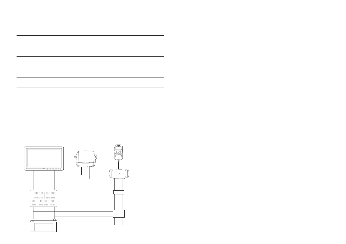
Audio noise
To minimise audio noise on VHF radio or other audio equipment
it is recommended that a suitable noise filter is installed in the
power cable of the VHF/audio equipment and connections to the
boat’s power supply are made as shown in the following
diagram:
Monitor
Distribution
panel
Autopilot
Noise
filter
VHF Radio
Audio
equipment
Viewing Angle Considerations
There are several factors to consider prior to installing your new
Raymarine display that could effect the usability of the product.
These are listed in the installation guide supplied with this
product.
Note: Raymarine strongly recommends you pay close attention
to the viewing angle of displays in the preparation stage of the
installation considering the following....
Contrast and Color
Contrast and Color can be affected by viewing angle. Raymarine
recommends you power your display while you prepare your installation to see the best mounting angle for all situations (in both
day and night mode).
Night Mode
If you plan to use the display in night mode make sure to enable
the “Red Mode” during the display mounting selection process
as the removal of certain colors when in Night Mode has an
overall effect on viewing angle that needs to be considered.
Boat's
battery
Circuit
breaker
 Loading...