

Page 1

E-Series
Networked
Display
Reference Manual
Document number: 81244_2
Date: March 2006
Page 2

E-Series Reference Manual
Trademarks and registered trademarks
Autohelm, HSB, Raymarine, RayTech Navigator, Sail Pilot, SeaTalk and Sportpilot are registered
trademarks of Raymarine Limited. Apelco is a registered trademark of Raymarine Holdings Limited
(registered in all major marketing territories).
AST, Autoadapt, Auto GST, Autoseastate, Autotrim, Bidata, Marine Intelligence, Maxiview, On Board,
Raychart, Raynav, Raypilot, Raystar, ST40, ST60, Seaclutter, Smart Route, Tridata and Waypoint
Navigation are trademarks of Raymarine Limited.
Navionics is a registered trademark of Navionics Company, Italy.
All other product names are trademarks or registered trademarks of their respective owners.
Software in this product is based in part on the work of the Independent JPEG Group.
Contents of this handbook ©Raymarine plc 2006.
Copyright Notice
libwww Copyright Notice
libwww
Copyright
National de Recherche en Informatique et en Automatique, Keio University). All Rights Reserved. This
program is distributed under the W3C's Software Intell ectual Property License
in the hope that it will be useful, but WITHOUT ANY WARRANTY; without even the implied warranty of
MERCHANTABILITY or FITNESS FOR A PARTICULAR PURPOSE. See W3C License http://www.w3.org/
Consortium/Legal/ for more details.
Copyright © 1995 CERN
This acknowledgment shall be mentioned in full in any product which includes the CERN computer
software included herein or parts thereof."
W3C® SOFTWARE NOTICE AND LICENSE
http://www.w3.org/Consortium/Legal/2002/copyright-software-20021231
1. The full text of this NOTICE in a location viewable to users of the redistributed or derivative work.
2. Any pre-existing intellectual property disclaimers, notices, or terms and conditions. If none exist, the
3. Notice of any changes or modifications to the files, including the date changes were made. (We rec-
THIS SOFTWARE AND DOCUMENTATION IS PROVIDED "AS IS," AND COPYRIGHT HOLDERS MAKE NO
REPRESENTATIONS OR WARRANTIES, EXPRESS OR IMPLIED, INCLUDING BUT NOT LIMITED TO,
WARRANTIES OF MERCHANTABILITY OR FITNESS FOR ANY PARTICULAR PURPOSE OR THAT THE USE OF
THE SOFTWARE OR DOCUMENTATION WILL NOT INFRINGE ANY THIRD PARTY PATENTS, COPYRIGHTS,
TRADEMARKS OR OTHER RIGHTS.
COPYRIGHT HOLDERS WILL NOT BE LIABLE FOR ANY DIRECT, INDIRECT, SPECIAL OR CONSEQUENTIAL
DAMAGES ARISING OUT OF ANY USE OF THE SOFTWARE OR DOCUMENTATION.
This formulation of W3C's notice and license became active on December 31 2002. This version removes
the copyright ownership notice such that this license can be used with materials other than those owned
by the W3C, reflects that ERCIM is now a host of the W3C, includes references to this specific dated
version of the license, and removes the ambiguous grant of "use".
: W3C's implementation of HTTP can be found at: http://www.w3.org/Library/
© 1994-2000 World Wide Web Consortium, (Massachusetts Institute of Technology, Institut
. This program is distributed
. "This product includes computer software created and made available by CERN.
W3C Software Short Notice
body of any redistributed or derivative code.
ommend you provide URIs to the location from which the code is derived.)
should be included (hypertext is preferred, text is permitted) within the
Copyright status
Libwww software that was developed inside W3C will continue to be protected under the W3C Software
License. Future work on libwww will remain accessible to public and as such is protected under the W3C
Software License or a similar Open Source License, such as GPL.
Page 3

Important information i
Important Information
Intended use
The display units detailed in this handbook may form part of marine navigational radar
system or GPS system intended for use on (non-IMO/SOLAS class) leisure vessels or
small workboats.
This handbook contains important information on the operation and maintenance of
your E-Series Display. To get the best results in operation and performance, please take
the time to read this handbook thoroughly.
For full details of installation and system integration, please refer to the E-Series
Installation Guide supplied with the display.
Safety notices
WARNING:Navigation Aid
This device is intended to be used as an aid to navigation. Its
accuracy can be affected by many factors, including equipment
failure or defects, environmental conditions and incorrect
handling or use. It is the user’s responsibility to exercise common
prudence and navigational judgement. This device should not be
relied upon as a substitute for such prudence and judgement.
WARNING:Product installation
This equipment must be installed in accordance with the
instructions in the E-Series System Installation Guide. Failure to do
so could result in poor product performance, personal injury and/
or damage to the vessel.
WARNING:High voltage
The display unit and scanner unit contain high voltages.
Adjustments require specialized service procedures and tools only
available to qualified service technicians - there are no user
serviceable parts or adjustments. The operator should never
remove the display unit cover or attempt to service the
equipment.
WARNING:Electromagnetic energy
The radar scanner transmits electromagnetic energy. Ensure that
the scanner has been installed according to the recommendations
given in the relevant scanner handbook. Avoid looking directly at
the antenna.
Page 4

ii E-Series Networked Display Reference Manual
WARNING:Fishfinder sounder module
Removing the transducer cable from the rear of the fishfinder
sounder module whilst it is switched on can cause sparks. Only
remove the transducer cable after power has been switched off.
Ensure that the sounder module is mounted where it is well
ventilated and in an area free from flammable vapors.
CAUTION: Water Ingress
To prevent the ingress of water and consequent damage to the display,
ensure that the chart card door is firmly closed. This can be confirmed by an
audible click.
CAUTION: CompactFlash Cards
• Removing the CompactFlash card whilst information is being written to
or read from it may cause damage to the card and loss of all data. Use the
proper procedure detailed on page 20 to remove the card.
• Only one CompactFlash card per display can be used at any one time.
• Do not save data (waypoints, routes etc.) to a Navionics card as the charts
may be overwritten. When archiving use a different CompactFlash card.
• DO NOT use a metallic instrument such as a screwdriver or pliers to help you
remove a card, as doing this can cause irreparable damage.
CAUTION: Global Positioning System Antenna
Do not connect or disconnect the GPS antenna from the display unit whilst
power is switched on. Doing this may result in irreparable damage.
CAUTION: UV Light
To provide protection against the damaging effects of UV light, it is advisable
to replace the sun cover provided when the display is not in use.
CAUTION: Cleaning the display
Take care when cleaning the display, to avoid damaging it:
(1) Do NOT wipe the display screen with a dry cloth, as this could scratch
(2) Do NOT use acid, ammonia based or abrasive products.
Disclaimers
Electronic charts are an aid to navigation designed to facilitate the use of authorized
government charts, not to replace them. Only official government charts and notices to
mariners contain the current information needed for safe navigation. The Captain is
responsible for their prudent use. The E-Series and its charts do not therefore exclude
the user from carrying the required official charts and documents.
Raymarine does not warrant that this product is error-free or that it is compatible with
products manufactured by any person or entity other than Raymarine.
the screen coating.
This product uses digital chart data, and electronic information from the Global
Positioning System (GPS) which may contain errors. Raymarine does not warrant the
accuracy of such information and you are advised that errors in such information may
cause the product to malfunction. Raymarine is not responsible for damages or injuries
Page 5

Important information iii
caused by your use or inability to use the product, by the interaction of the product with
products manufactured by others, or by errors in chart data or information utilized by
the product and supplied by third parties.
Weather services
All information presented by this service is advisory only. You acknowledge the risk of
incomplete and erroneous information and assume complete responsibility and risks
associated with this device, and accordingly release Raymarine, Sirius Satellite Radio
Inc. and WSI Corporation from any and all claims arising from the use of this service. By
using this service, you acknowledge and agree that you have read the terms of the
subscription agreement for this service and agree to all of the terms contained therein.
If you do not have the subscription agreement, you may view a copy on the internet at
www. Sirius.com/marineweatheragreement or call 1-800-869_5480
sent to you.
for a copy to be
About this manual
This manual describes how to operate your E-Series display in conjunction with
Navionics cartography. It assumes that all peripheral equipment to be operated with it
is compatible and has been correctly installed.
This manual is intended for users of varying marine abilities, but assumes a general
level of knowledge of display use, nautical terminology and practices.
Raymarine does not necessarily support all the features in particular Navionics
cartography.
Technical accuracy
To the best of our knowledge, the technical information contained within this
handbook, was correct at the time of printing. However, Raymarine cannot accept
liability for any inaccuracies or omissions it may contain.
In addition, Raymarine’s policy of continuous product improvement may change
specifications without notice. As a result Raymarine cannot accept liability for any
differences between the product and this handbook.
Raymarine does not support after-sales or technical support for Navionics chart cards.
If you wish to file a report of an error or omission on a Navionics chart, please provide
the information to the Navionics web site at the link below:
http://www.navionics.com/DiscrepancyReports.asp
Page 6

iv E-Series Networked Display Reference Manual
EMC conformance
All Raymarine equipment and accessories are designed to the best industry standards
for use in the recreational marine environment. Their design and manufacture
conforms to the appropriate Electromagnetic Compatibility (EMC) standards, but
correct installation is required to ensure that performance is not compromised.
Multi-media chart cards
To use your E-Series Display as a navigation aid, charts with the appropriate level of
detail for the geographic area you wish to navigate are required. The charts are
available in electronic format on Navionics Chart cards.
To check the current availability of Navionics® chart card types and the latest feature
sets, visit www.navionics.com or www.navionics.it.
To obtain Navionics cards, contact your local dealer or visit the Navionics web site.
Alternatively, anywhere in North America call Navionics toll-free on 1-800-848-5896
Outside of North America, contact your local dealer or Navionics SpA on:
Disposal
Phone: (+39) 0584 961696 or Fax: (+39) 0584 961309)
When archiving data, Raymarine recommends that you only use SanDisk CF memory
cards. Other brands of CF memory card may not work in your E-Series Display.
Waste Electrical and Electronic Equipment (WEEE) Directive
The WEEE Directive requires the recycling of waste electrical and electronic
equipment. Whilst the WEEE Directive does not apply to some of Raymarine’s
products, we support its requirements as part of our environmental policy and
we ask you to be aware of how you should dispose of this product.
The crossed-out wheelie bin symbol found on our products signifies that it should not
be disposed of in general waste or landfill.
Please contact your local dealer, national distributor or Raymarine Technical Services
for information on product disposal.
Page 7

Contents v
Contents
Chapter 1: Overview ..................................................................................................1
1.1 What will my E-Series integrate with? .................................................................. 1
1.2 What can the E-Series Display do? ........................................................................2
1.3 The Simulator ........................................................................................................ 5
Chapter 2: General Operation ..................................................................................7
2.1 Introduction ..........................................................................................................7
2.2 Powering the display ON/OFF ............................................................................... 7
2.3 Using the controls ................................................................................................. 8
The control panel ............................................................................................ 8
Buttons and soft keys ...................................................................................... 9
The cursor .....................................................................................................10
2.4 Displaying applications ....................................................................................... 10
2.5 Additional screen information ............................................................................ 11
2.6 Initial setup procedures ...................................................................................... 15
Selecting the data master (Networked E-Series only) .................................... 15
Setting the language, date/time format and units of measurement ..............15
Selecting a page set ......................................................................................16
Selecting an application page ....................................................................... 16
Selecting an application window .................................................................. 17
Adjusting the display lighting ........................................................................ 18
2.7 Using CompactFlash cards ..................................................................................19
Cautions ........................................................................................................ 19
What are CompactFlash cards used for? ....................................................... 19
Inserting a card .............................................................................................20
Removing a card ...........................................................................................20
2.8 Managing data ................................................................................................... 21
Writing/retrieving data to a CompactFlash card ............................................ 21
Sending and receiving information using a PC .............................................. 25
Password protecting your waypoints ............................................................ 25
2.9 Operating a networked E-Series Display .............................................................28
What does a networked system do? .............................................................. 28
Controlling a network ................................................................................... 28
Functions only affecting the display in use ....................................................29
Page 8

vi E-Series Networked Display Reference Manual
2.10 Emergencies and warnings ................................................................................. 30
Man Overboard (MOB) ................................................................................. 30
Alarms ..........................................................................................................31
Chapter 3: Working with Waypoints .....................................................................33
3.1 What is a waypoint? ........................................................................................... 33
3.2 How are waypoints represented? .......................................................................34
3.3 Placing a waypoint .............................................................................................35
3.4 Navigating to a waypoint ...................................................................................36
Start navigating to a waypoint ......................................................................36
Stop navigating to a waypoint ......................................................................37
3.5 Viewing waypoint information ........................................................................... 37
3.6 Editing a waypoint ..............................................................................................38
Changing waypoint details ...........................................................................39
Moving a waypoint ....................................................................................... 39
Erasing a waypoint(s) .................................................................................... 40
Changing the default symbol or group ..........................................................41
3.7 Sorting the waypoint list .....................................................................................42
3.8 Organising waypoints into groups ...................................................................... 42
Displaying the waypoint group list ................................................................ 42
Making a new waypoint group .....................................................................43
Moving waypoints between groups .............................................................. 43
Renaming an existing group .........................................................................44
Erasing a group ............................................................................................. 45
3.9 Controlling waypoint display .............................................................................. 45
Show/hide waypoint names .......................................................................... 45
Showing/hiding waypoint symbols ............................................................... 46
Showing/hiding waypoint groups ................................................................. 46
Chapter 4: Using the Chart ......................................................................................47
4.1 Important ...........................................................................................................47
Safety ............................................................................................................47
Chart functionality ........................................................................................47
Chart cards .................................................................................................... 48
4.2 Uses of the chart application .............................................................................. 48
4.3 Viewing the chart ................................................................................................ 49
4.4 The chart display ................................................................................................. 49
Page 9

Contents vii
4.5 Where am I on the chart? .................................................................................... 50
4.6 Moving around the chart .................................................................................... 50
4.7 Additional information on the chart ................................................................... 51
Displaying details of objects and features ..................................................... 52
Finding nearby features and services ............................................................52
Displaying details of tides ............................................................................. 53
Displaying details of currents ........................................................................ 54
Displaying details of port services ................................................................. 54
Pilot book information ..................................................................................57
Displaying panoramic photos ........................................................................ 58
Displaying details of business services & points of interest ...........................59
Displaying an aerial photo overlay ................................................................ 60
Displaying vessel identity (AIS) ..................................................................... 62
4.8 Measuring distances and bearings .....................................................................63
... from your boat ...........................................................................................63
... between two points on your chart .............................................................63
4.9 Navigating to a specific point ............................................................................. 64
Go to an existing waypoint ........................................................................... 65
Resetting cross track error (XTE) ................................................................... 65
Arriving at your target waypoint ................................................................... 65
Stop navigating to your target waypoint .......................................................66
Maintaining a view of your navigation .......................................................... 66
4.10 Building and following a route ............................................................................ 67
What is a route? ............................................................................................ 67
What can I do with a route? .......................................................................... 67
Building a route ............................................................................................. 68
Following a route .......................................................................................... 72
Resetting cross track error (XTE) ................................................................... 74
Viewing details of routes ...............................................................................75
4.11 Editing routes ..................................................................................................... 76
Selecting a route for editing .......................................................................... 76
Editing the selected route ............................................................................. 77
4.12 Monitoring where you are going ........................................................................ 82
... using chart vectors .................................................................................... 82
... using the Course Deviation Indicator (CDI) ................................................ 83
4.13 Warnings of potential dangers ............................................................................ 83
Page 10

viii E-Series Networked Display Reference Manual
4.14 Using the radar with the chart ............................................................................84
Synchronizing the chart with radar range ..................................................... 84
Viewing MARPA targets on the chart ............................................................84
Distinguishing between fixed and moving objects ........................................85
4.15 Recording where you have been ......................................................................... 86
What is a track? ............................................................................................ 86
How can I use tracks? ....................................................................................87
Creating a track ............................................................................................. 87
Creating a route from a track ........................................................................88
4.16 Editing tracks ......................................................................................................89
Selecting a track for editing ........................................................................... 89
Editing the selected track ..............................................................................90
4.17 Defining how the chart windows are presented ................................................. 91
Working with multiple chart views ................................................................ 91
Setting the orientation of the chart ...............................................................92
Setting the motion mode .............................................................................. 93
4.18 Altering the level of chart detail displayed ..........................................................94
Showing or hiding waypoints/waypoint information .................................... 95
Showing or hiding a route or a track ............................................................. 96
Showing or hiding cartographic features ...................................................... 97
4.19 Setting up your chart and its cartography ........................................................... 98
Chart Setup ...................................................................................................98
Cartography Setup ...................................................................................... 101
Chapter 5: 3D Chart ................................................................................................103
5.1 Important .........................................................................................................103
3D Chart functionality ................................................................................. 103
Safety ..........................................................................................................103
5.2 An introduction ................................................................................................. 103
5.3 What can I use the 3D Chart Application for? ...................................................104
5.4 The 3D chart display ..........................................................................................104
5.5 Where am I on the 3D chart? ............................................................................105
5.6 Moving around the 3D chart .............................................................................105
5.7 Other 3D controls ............................................................................................. 106
Soft keys ...................................................................................................... 106
5.8 Changing the mode ..........................................................................................107
Page 11

Contents ix
Active motion mode .................................................................................... 107
Planning mode ............................................................................................107
5.9 Changing the view ............................................................................................ 108
View options ............................................................................................... 108
Multiple views ............................................................................................109
Vessel offset ................................................................................................109
5.10 Aerial photo overlay ......................................................................................... 110
5.11 Making the view clearer ...................................................................................110
Exaggeration ..............................................................................................110
Declutter .....................................................................................................111
5.12 Using 2D and 3D charts together ......................................................................112
3D view locator ........................................................................................... 112
Chart synchronization .................................................................................113
5.13 Using the 3D chart with a fishfinder .................................................................. 114
5.14 Navigating with 3D charts ................................................................................ 114
5.15 Setting up the 3D Chart .................................................................................... 115
Chapter 6: Using the Fishfinder ............................................................................117
6.1 Introduction ......................................................................................................117
6.2 How does the Fishfinder work? ......................................................................... 117
6.3 What can the fishfinder show me? .................................................................... 118
Interpreting the bottom structure ............................................................... 119
Factors influencing target display ................................................................119
Factors impairing a fishfinder picture ..........................................................120
Seeing a live image .....................................................................................120
6.4 Enhancing what you see ................................................................................... 122
Changing the range .................................................................................... 122
Shifting the image .......................................................................................122
Zooming in on the bottom ...........................................................................123
Simplifying the bottom image .....................................................................125
Isolating bottom fish ...................................................................................126
Changing how the image scrolls ................................................................. 127
Changing how the depth digit is displayed .................................................128
6.5 Marking a position ............................................................................................129
6.6 Determining depths and distances of targets .................................................... 130
Measuring using VRMs ...............................................................................131
Page 12

x E-Series Networked Display Reference Manual
6.7 Fishfinder alarms .............................................................................................. 132
6.8 Setting up your fishfinder ..................................................................................132
Display settings ...........................................................................................133
Transducer Calibration ................................................................................ 134
DSM Setup ..................................................................................................135
6.9 Other settings affecting the fishfinder image .................................................... 136
Operating frequency modes ........................................................................ 136
Gain modes ................................................................................................. 137
Adjusting the power setting ........................................................................139
Chapter 7: Using the Radar ...................................................................................141
7.1 Introduction ......................................................................................................141
7.2 What is radar? .................................................................................................. 141
Detecting targets ........................................................................................ 141
Maximum radar range ................................................................................142
Factors impairing a radar picture ................................................................. 142
7.3 Powering on/off the various scanner operating modes .....................................146
7.4 The radar picture ............................................................................................... 147
7.5 Marking a position on the radar screen ............................................................ 148
7.6 Changing what you see in the radar window .................................................... 148
Setting the orientation of the radar .............................................................148
Setting the motion mode ............................................................................ 150
Showing or hiding the range rings .............................................................. 152
Changing the bearing mode for EBLs ..........................................................152
7.7 Getting the best picture ....................................................................................152
Using the GAIN functions ............................................................................ 152
Using the enhance echoes functions ...........................................................154
7.8 Changing the displayed range ..........................................................................157
Radar range and chart scale synchronization ..............................................157
7.9 Measuring distances, ranges and bearings ....................................................... 158
... Using the range rings ..............................................................................158
... Using the cursor ......................................................................................158
... Using VRMs and EBLs .............................................................................. 159
... Using floating VRMs/EBLs .......................................................................161
7.10 Using radar to avoid a collision ......................................................................... 162
Guard Zones ............................................................................................... 162
MARPA ....................................................................................................... 165
Page 13

Contents xi
Setting up MARPA ....................................................................................... 168
Acquiring a target to track ..........................................................................169
Cancelling targets ....................................................................................... 169
Displaying vessel identity (AIS) ................................................................... 170
7.11 Setting up your radar ........................................................................................ 170
7.12 Warnings of potential dangers .......................................................................... 172
Chapter 8: Using the data application ................................................................173
8.1 Introduction ......................................................................................................173
8.2 Selecting a data application .............................................................................. 173
8.3 Selecting the data for display ............................................................................ 174
Pre-configured data panels ......................................................................... 174
Customize the panels ..................................................................................175
Chapter 9: Video .....................................................................................................179
9.1 Introduction ......................................................................................................179
9.2 Setting up the video application ....................................................................... 179
Displaying a video application .................................................................... 179
Customizing the video application .............................................................. 180
Adjusting the image ....................................................................................183
Chapter 10: Using the Course Deviation Indicator ..............................................185
10.1 Introduction ......................................................................................................185
10.2 The CDI screen .................................................................................................. 185
Steering instructions ................................................................................... 186
10.3 Selecting the CDI application ............................................................................ 186
10.4 Modifying the CDI application .......................................................................... 186
Chapter 11: Using the Engine Monitor ..................................................................187
11.1 Introduction ......................................................................................................187
11.2 Displaying and setting up the engine monitor .................................................. 187
11.3 The engine monitor display ...............................................................................189
11.4 Configuring the engine panels. ......................................................................... 189
11.5 What should I do when an alarm is triggered? .................................................. 189
Chapter 12: Weather (US only) ...............................................................................191
12.1 Overview ..........................................................................................................191
12.2 Important information ...................................................................................... 191
Page 14

xii E-Series Networked Display Reference Manual
Disclaimer ...................................................................................................191
12.3 Setting up the weather application ...................................................................191
Pre-requisites for using the weather application .........................................192
Adding a weather application .....................................................................192
Specifying the weather elements ................................................................ 192
12.4 The weather display ..........................................................................................193
12.5 Moving around the weather map ..................................................................... 193
12.6 Placing waypoints .............................................................................................193
12.7 Weather graphics ............................................................................................. 194
Precipitation (NOWRad) ..............................................................................195
Storm Cast ..................................................................................................195
Sea surface temperature (SST) ....................................................................196
Canadian radar ........................................................................................... 196
Tracking storms ...........................................................................................196
Lightning .....................................................................................................197
Surface observation stations .......................................................................197
City forecasts .............................................................................................. 198
Wind ...........................................................................................................199
Waves .........................................................................................................199
Surface pressure ..........................................................................................200
Viewing data at a particular location ..........................................................200
12.8 Animated weather graphics ............................................................................. 200
Setting up animation ...................................................................................200
Running animation .....................................................................................201
12.9 Viewing weather reports ..................................................................................201
Tropical statements .....................................................................................201
Marine warnings .........................................................................................202
Marine zone forecasts ................................................................................. 202
12.10Watchbox warnings .......................................................................................... 203
Watchbox warning alerts ............................................................................ 203
Displaying marine watchboxes ................................................................... 204
Displaying watchbox data ........................................................................... 204
12.11Weather application setup ...............................................................................205
Selecting the Weather Setup Menu .............................................................205
Weather Setup options ................................................................................ 205
Showing/hiding marine watchboxes and zone boundaries .........................205
Page 15

Contents xiii
12.12Troubleshooting ...............................................................................................206
Chapter 13: Navtex ..................................................................................................207
13.1 Overview ..........................................................................................................207
13.2 Setting up Navtex weather ...............................................................................207
13.3 Incoming message alerts ..................................................................................207
13.4 Viewing messages ............................................................................................208
Displaying the Navtex Message List ............................................................208
Displaying and scrolling through a message ............................................... 208
13.5 Managing Navtex messages ............................................................................ 208
Selecting message alert categories ............................................................. 208
Sorting the message list ..............................................................................209
Chapter 14: Automatic Identification System (AIS) ............................................211
14.1 Introduction ......................................................................................................211
14.2 What is AIS? ..................................................................................................... 211
Classes of AIS data ...................................................................................... 211
14.3 What do I need to run AIS? ...............................................................................213
14.4 Selecting the AIS function .................................................................................213
AIS status .................................................................................................... 213
14.5 How is AIS data displayed? ...............................................................................214
AIS Target symbols ...................................................................................... 214
Viewing target information .........................................................................215
14.6 Using AIS for collision avoidance ......................................................................217
Safe zones ...................................................................................................217
MARPA and AIS options .............................................................................. 218
Safety messages ......................................................................................... 218
14.7 AIS Alarms ........................................................................................................ 218
Local AIS alarms ..........................................................................................219
Active alarm list .......................................................................................... 219
14.8 Simulator ..........................................................................................................220
14.9 AIS Layer Setup Menu ....................................................................................... 220
Chapter 15: System setup and customizing .........................................................221
15.1 Changing the data master ................................................................................ 221
15.2 Customizing the page sets ................................................................................221
Reconfiguring the application and page layout ...........................................221
Page 16

xiv E-Series Networked Display Reference Manual
Rename a page set ...................................................................................... 222
Return to default setting ............................................................................. 222
15.3 Changing the databar ....................................................................................... 223
Databar position .........................................................................................223
Data bar size ............................................................................................... 223
Customizing the contents of the data bar ...................................................224
15.4 Changing the set up menu options ................................................................... 227
Application specific ..................................................................................... 227
External equipment menus ......................................................................... 227
System-wide menus ....................................................................................227
Chapter 16: Maintenance & Troubleshooting ......................................................239
16.1 Introduction ......................................................................................................239
16.2 Maintenance procedures ..................................................................................239
Servicing and Safety ....................................................................................239
Routine checks ............................................................................................239
Cleaning the display .................................................................................... 240
16.3 Resetting the Display ........................................................................................240
Settings reset .............................................................................................. 240
Settings and data reset ............................................................................... 241
16.4 Troubleshooting your Display ........................................................................... 241
Common problems and how to solve them .................................................241
16.5 Getting Technical Support .................................................................................244
For Raymarine products .............................................................................. 244
For Navionics cartography ..........................................................................247
For Sirius weather .......................................................................................248
Appendix A: Specification for the E80 and E120 Displays ...................................249
Appendix B: List of Abbreviations ..........................................................................257
Appendix C: List of cursor labels .............................................................................259
Appendix D: Glossary of weather terms ................................................................261
Page 17
Chapter 1: Overview 1
Chapter 1: Overview
This chapter gives an overview of the E-Series display system and its features.
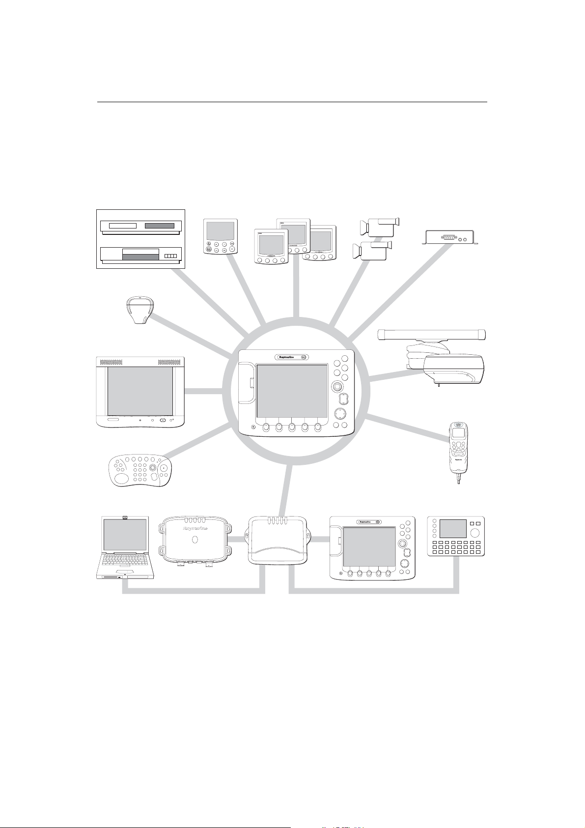
1.1 What will my E-Series integrate with?
DVD
DVD
23.47
Video
VIDEO
23.47
GPS
Autopilot
Instruments
Cameras
AIS receiver
Radar scanner
M1500 or monitor
Remote keyboard
Personal Computer Fishfinder DSM 300
When used as part of a SeaTalk system it will display information from other SeaTalk
and NMEA instruments. It can also be networked with other E-Series displays by way
of Raymarine’s SeaTalk High Speed switch. Information from the E-Series display can
be transferred between applications and to other SeaTalk instruments within the
system. For more detail on system integration, please refer to the Installation Guide.
SeaTalk
switch
E-Series display
HS
PAGE
ACTIVE
WPTS
MOB
DATA
MENU
OUT
RANGE
IN
CANCELOK
E-Series additional displays
ACTIVE
DATA
PAGE
WPTS
MOB
MENU
OUT
RANGE
IN
CANCELOK
DSC VHF
11.18.02
RAY240
OK
MENU
CH
16/9
HI/LO
WX
SCAN WATCH
SQ
Weather receiver
D7514_2
Page 18
2 E-Series Networked Display Reference Manual
1.2 What can the E-Series Display do?
With the appropriate equipment connected to your system and the necessary data
available, your E-Series display combines the following applications which are used to:
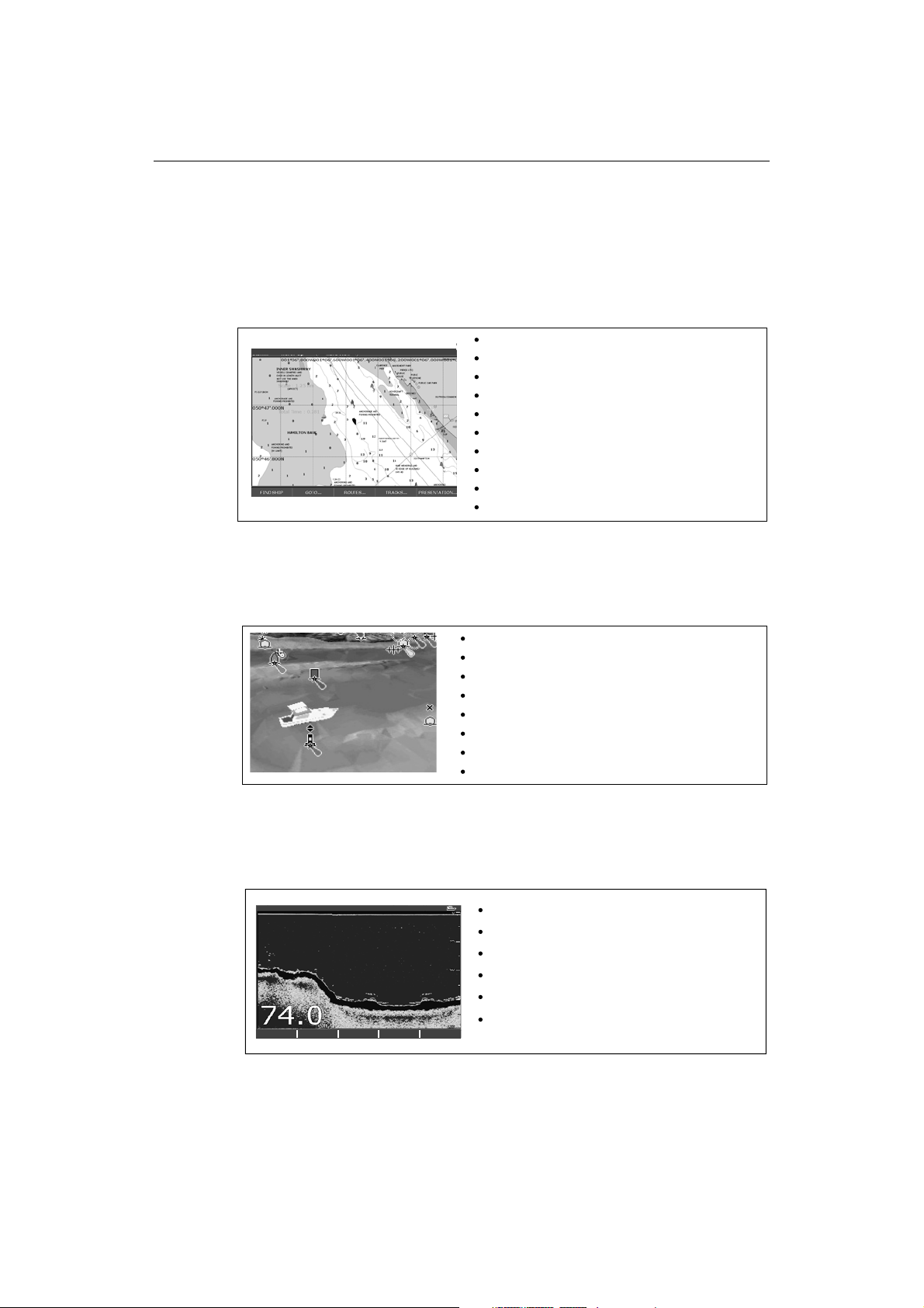
Chart (Chapter 4)
0.5nm North-Up (Relative Motion) Local
You will need a chart card, and position/heading data, for the chart application to be
fully functional.
Locate where you are.
Interpret your surroundings.
Monitor where you are going.
Record where you have been.
Navigate to a specified position (waypoint).
Build and navigate routes.
View details of nearby features & services.
View details of boats equipped with AIS.
Distinguish between fixed and moving objects.
Measure distances and bearings.
D7363_2
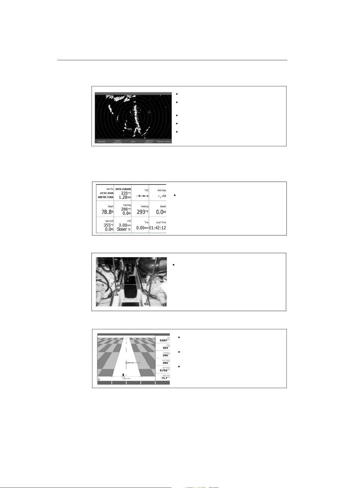
3-D Chart (Chapter 5)
Display a 3D view of land, sea & features.
Locate where you are.
Interpret your surroundings.
Draft
Monitor where you are going.
Go to an existing waypoint.
Navigate a route.
Synchronize with the 2D chart.
Identify fishing spots
You will need a chart card and accurate heading and position data for your 3D chart
application to be fully functional.
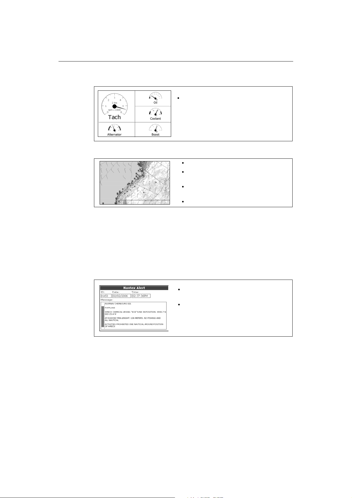
Fishfinder (Chapter 6)
200kHz: Auto Range: Auto
TRANSDUCER
ZOOM… BOTTOM LOCK… A-SCOPE… PRESENTATION…
SETTINGS…
You will need position data, in addition to a DSM300, for your fishfinder to be fully
functional.
Build a picture of what is below your vessel.
Locate & distinguish underwater objects & targets.
Distinguish the seabed and its texture.
Obtain information about water depth, temperature.
Mark a point of interest, fishing spot etc.
Determine depths and distances of targets.
D8702_1
D7377-1
Page 19
Chapter 1: Overview 3
Radar (Chapter 7)
6nm North-Up (Relative Motion) Rings 1nm
Detect landmasses & navigation markers.
Detect and measure the range and distance of other
vessels.
Acquire targets and track them for collision avoidance.
Navigate to a specified position (waypoint).
TARGET
VRM/EBL... GAIN...
TRACKING...
TARGETS
DISPLAY...
PRESENTATION...
View details of boats equipped with AIS.
You will need position and heading data, in addition to a compatible scanner, for your
radar application to be fully functional.
Data (Chapter 8)
View data generated by the system or by instruments
available on NMEA 0183, NMEA 2000 and SeaTalk or
2
.
SeaTalk
Video (Chapter 9)
D7375-2
D7376-1
View video images from on-board CCTV cameras, DVD or
video player.
Draft
Course Deviation Indicator (Chapter 10)
3nm North-Up Relative Motion Local
You will need accurate heading and position data for your CDI application to be fully
functional.
View real-time display of your vessel on a 'rolling
road' in 3D perspective.
Give details of any correction required to steer your
vessel along a given course.
View data about the distance and time to go until
you reach a specified point.
D7378-1
D7379-1
Page 20
4 E-Series Networked Display Reference Manual
Engine Monitor (Chapter 11)
T
View engine data e.g. engine temperature, oil pressure,
fuel level etc from up to three engines on a compatible
engine system.
Weather (Chapter 12)
Only available for the US.
Superimpose historical and forecasted weather graphics
on a world map.
Determine conditions in your vicinity or at a particular
location.
View weather reports.
You will need accurate position data and be connected to a Sirius weather receiver
(which is supplying the appropriate data) for your Weather application to be fully
functional.
D7497-1
D8701-1
Navtex (Chapter 13)
Major areas of NAVTEX coverage include the Mediterranean Sea, the North Sea,
coastal areas around Japan and areas around the North American continent.
Automatic broadcast of localised Maritime Safety
Information (MSI)
Draft
Receive navigational and meteorological warnings, and
search and rescue information.
You will need a Navtex receiver connected to your system via NMEA, in order to receive
this data.
Waypoints (Chapter 3) & AIS (Chapter 14)
Whilst not applications in their own right, waypoints and AIS are handled at system
level and are covered in separate chapters.
D8728-1
Page 21

Chapter 1: Overview 5
1.3 The Simulator
The E-Series Display includes a simulator mode, which allows you to practice operating
your display without data from a GPS antenna, radar scanner. fishfinder or an AIS
receiver. The simulator mode is switched on/off in the System Setup Menu (see
page 262
• Before installation - Simply connect the display to a 12V DC power supply,
• After installation - Whilst in a marina or at anchor.
Please note that system settings made whilst in simulator mode, are not transmitted
via SeaTalk to other equipment.
Important: Incoming AIS safety messages cannot be displayed while the simulator is
switched on.
). Once enabled, you can use the simulator:
fused at 1 amp by attaching the red core from the power lead to positive (+) and
the black core to negative (-).
Page 22

6 E-Series Networked Display Reference Manual
Page 23

Chapter 2: General Operation 7
Chapter 2: General Operation
2.1 Introduction
This chapter gives details of the general operation of the E-Series display, and covers
the following subjects:
• Powering the display on/off.
• Using the controls.
• Application display.
• Displaying and editing additional information.
• Adjusting the display lighting.
• Initial setup procedures.
• Using CompactFlash cards.
• Managing data.
• Operating a networked E-Series Display.
• Emergencies and warnings.
2.2 Powering the display ON/OFF
Power ON
At this time the radar scanner (if fitted and powered) is checked for compatibility with
the display. An error message is displayed if the scanner is incompatible.
Power OFF
Remember to replace the suncover to protect the display.
Press the POWER button until the introductory logo is displayed. The keys
light up and after a few seconds an application page and a navigation
D6577-1
warning and weather data disclaimer is displayed. Read this information
and then press OK to remove it.
Press and hold the POWER button until the power down count reaches
zero. If the POWER button is released within the countdown period, power
off is cancelled.
Page 24
8 E-Series Networked Display Reference Manual
2.3 Using the controls
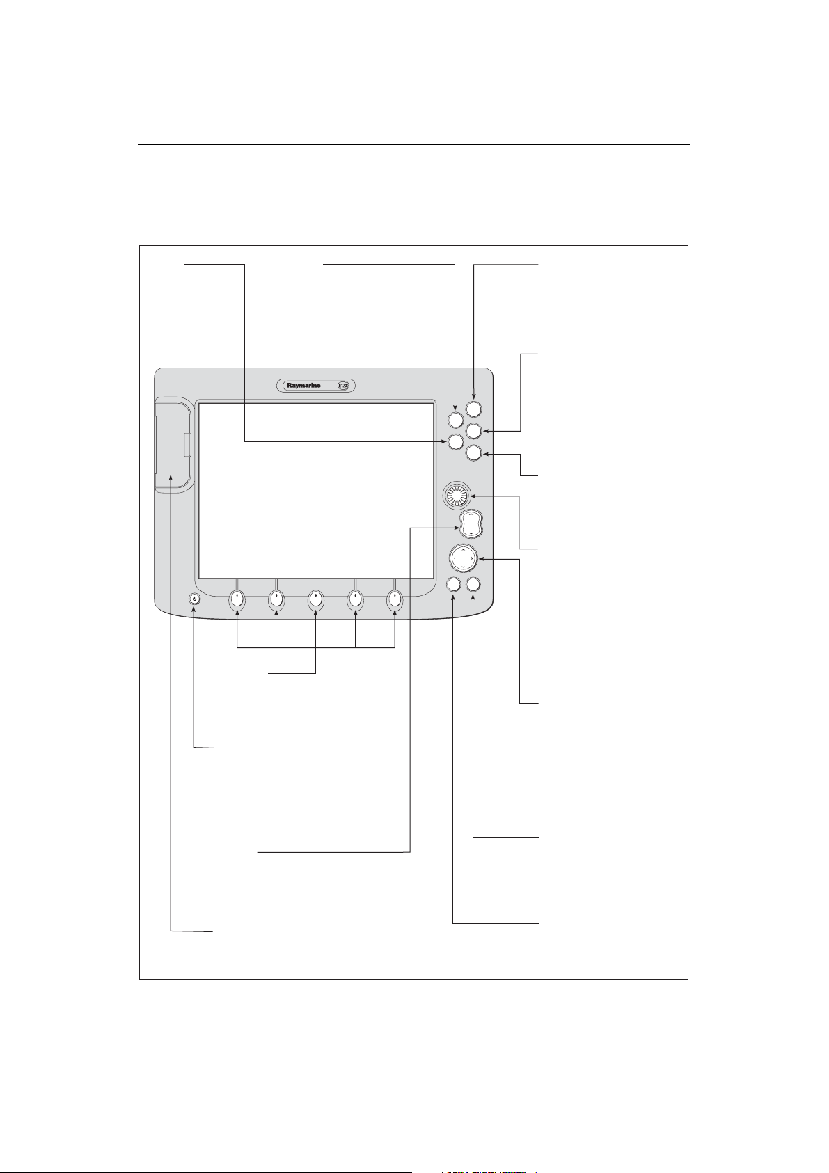
The control panel
DATA
Press to access
ruler, chart vectors,
archive & transfer
and data bar
on/off functions.
Softkeys
Press to select the corresponding function identified
by the on-screen label
Power
Press once to turn ON.
Press again to access
backlight functions and
scanner controls.
Press and hold to turn the
display OFF.
RANGE
Press to change the display
scale so that a smaller or
larger area can be seen on
the screen.
Chart Card slot
Open the cover to install
CompactFlash cards.
ACTIVE
When multiple windows are open:
- Press to select required window.
- Press and hold to maximise current
window.
- Press again to return to multiple
windows.
PAGE
Press to scroll through available
pages.
Press and hold to select different
page set or customise your own
layout.
WPTS/MOB
Press to display the waypoint
soft keys.
Press again to place waypoint at
PAGE
ACTIVE
WPTS
MOB
DATA
MENU
your boat's position.
Press and hold to place a
Man Overboard (MOB)
marker at your current position.
Press and hold again to exit
MENU
Press to access the set up
menus.
OUT
RANGE
IN
Press and hold to access help
information.
Rotary control
Use to edit alpha-numeric
CANCELOK
values, and scroll through lists.
Turn clockwise to increase
value and counter-clockwise to
decrease value.
Press to move the cursor to the
next character when editing
text.
Use to edit symbology (VRM/
EBL etc).
Trackpad
Used to control the on-screen
cursor and to scroll through
menu items.
Press the corresponding edge
of the trackpad to move the
cursor horizontally, vertically or
diagonally.
Press and hold to move rapidly
over larger distances.
CANCEL
Press to cancel the selected
on-screen option when editing
data; also used to return to
the previous soft key set or
menu.
OK
Press to select an on-screen
option, or return to the
previous soft key set or menu.
D7517_1
Page 25
Chapter 2: General Operation 9
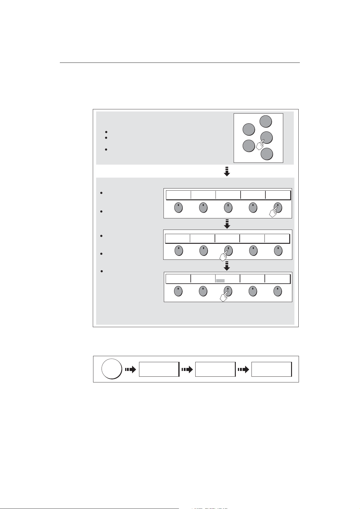
Buttons and soft keys
To navigate to the required function you will need to press a series of buttons and/or
soft keys:
Buttons
Access system functions or change what you see on-screen.
Within the text of this document they are written in bold capitals
e.g. WPTS/MOB.
Press and hold to access short cuts.
Soft keys
They change depending on
application or function
WAYPOINT AT
CURSOR
WAYPOINT AT
VESSEL
being performed.
Press the corresponding key
(below the screen) to select.
Further soft keys may be
displayed.
If a key has several options,
each press will highlight the
ERASE WAYPOINT SORT LIST
next option.
If a key displays a single
value or a slider above, use
the rotary control to adjust.
Within the text of this
document they are written
in capitals e.g. SORT LIST.
WAYPOINT AT
LAT/LONG...
SET DEFAULT SYM
& GROUP...
SET UP DEFAULT
SYMB GROUP
ACTIVE
DATA
GO TO WAYPOINT
OPTIONS…
WAYPOINT
GROUPS...
PAGE
WPTS
MOB
MENU
REVIEW AND EDIT
WAYPOINTS
VIEW AND EDIT
DETAILS…
EDIT DEFAULT
Example:
The example above shows the series of button and soft key presses
required to change the waypoint default symbol or group.
This process of pressing buttons and soft keys to navigate to the required function is
simplified in this manual and represented by a strip e.g.
WPTS
MOB
REVIEW AND EDIT
WAYPOINTS ...
SET DEFAULT SYM
& GROUP...
SET UP DEFAULT
SYMB GROUP
Note: The key beep that you hear whenever a button or soft key is pressed, can be
switched off and the soft keys automatically hidden if required. For more details,
please refer to the Display Setup Menu on page 236.
D7364-2
D7365-2
Page 26
10 E-Series Networked Display Reference Manual
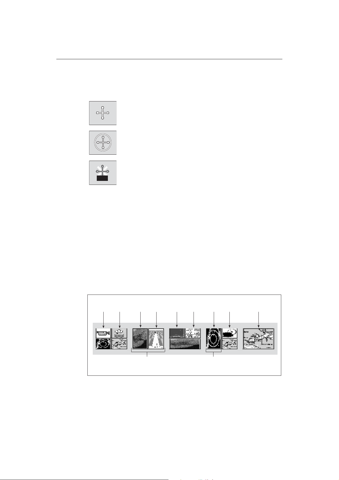
The cursor
When you are using the chart and radar applications, the cursor is used to move
around the screen:
The cursor appears on the screen as a white cross.
D7366_3
If the cursor has not been moved for a short period of time, it changes to
a circle with a cross in it, to make it easier to locate on the screen.
D7368_2
The cursor is context-sensitive - when it is placed over an object e.g. a
waypoint or chart feature, it changes color and a label or information
WPT
Notes: (1) For a full list of cursor labels and their meanings, please see
associated with the object is displayed. When you place the cursor over
D7369-2
certain items, the soft keys change to enable you to access related
operations.
Appendix C
(2) For details of how to temporarily hide the cursor, please see
page 236.
2.4 Displaying applications
The various applications that make up your E-Series system are displayed in a series of
screens known as
choose from. Each page set contains 5
windows
Page set
combined in various formats. Each window can display an application e.g.
Weather
Video
If necessary, you can change the combination and layout of these page sets to meet
your particular needs (see
page sets
3D Chart
(consists of 1, 2, 3 or 4 windows
in various configurations)
. There are 4 pre-configured and one empty page set to
CDI
Page
page 257
pages
Fishfinder
).
. These pages are made up of 1, 2, 3 or 4
Engine
Data
Radar
Window
monitor
2D Chart
D9025_1
Note: For details of how to select page sets, pages and windows, please refer to
page 16.
Page 27
Chapter 2: General Operation 11
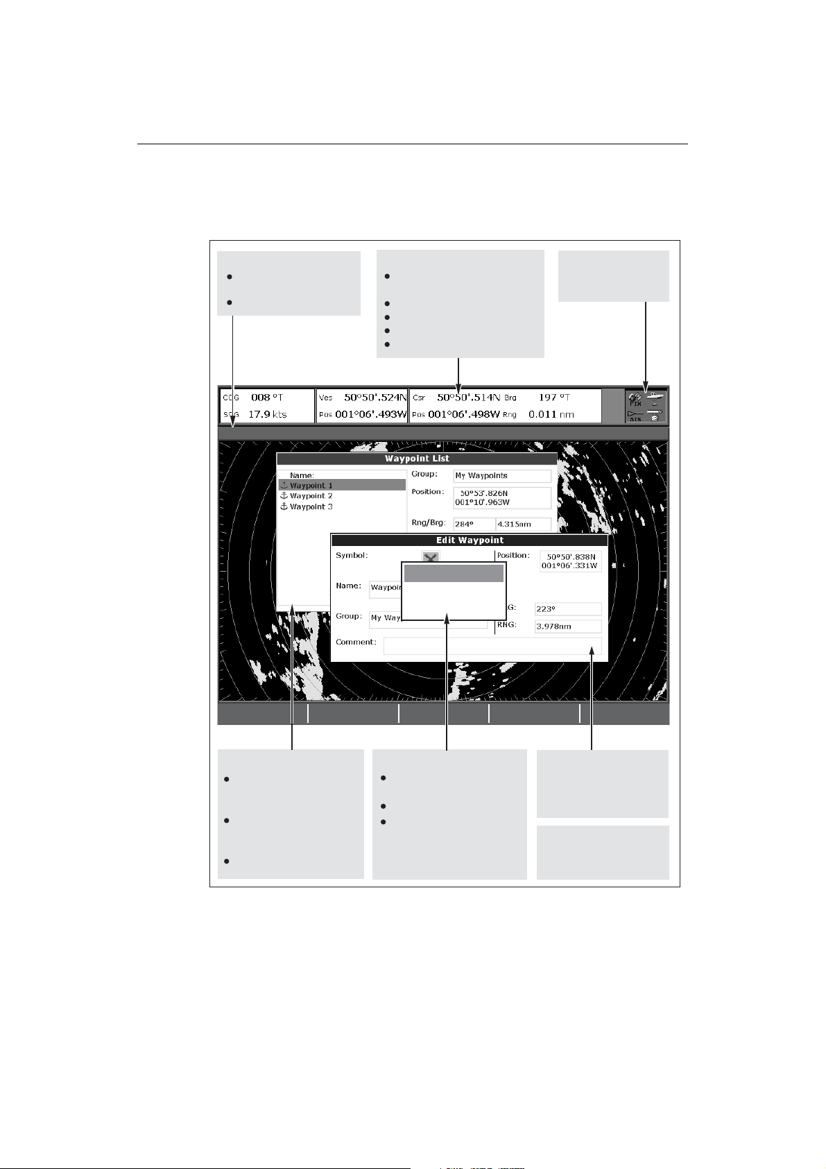
2.5 Additional screen information
Information is displayed on the screen using a variety of methods:
Status bar
Status bar
Gives information specific to
Gives information specific to
each application.
each application.
Cannot be edited or moved.
Cannot be edited or moved.
3nm
Head-Up Relative Motion Rings ½nm
3nm
Head-Up Relative Motion Rings ½nm
Data bar
Data bar
Gives information associated with
Gives information associated with
your boat or the environment.
your boat or the environment.
Customisable content*
Customisable content*
Vertical or horizontal format*
Vertical or horizontal format*
Display or hide*.
Display or hide*.
Normal or large size*.
Normal or large size*.
Status bar
Gives information specific to
each application.
MARPA ALARM
Target lost (on screen)
Target lost (on screen)
Cannot be edited or moved.
MARPA ALARM
Status icons
Status icons
Confirm status of DSM,
Confirm status of DSM,
GPS and scanner.
GPS, AIS and scanner.
ACKNOWLEDGE
ACKNOWLEDGE
Data base lists
Data base lists
Contain information you have
Contain information you
added to the display's memory
have added to the display's
e.g. waypoints.
memory e.g. waypoints.
Highlight an entry using
Highlight an entry with
trackpad or rotary control to
trackpad or rotary control to
display related information.
display related information.
Editable using soft keys.
Editable using soft keys.
* For details of how to adjust and edit the data bar, please see
Pop-up messages
Pop-up messages
Alert you to a situation e.g.
Alert you to a situation e.g.
alarm, function not available.
alarm, function not available.
Not editable.
Not editable.
May require a response e.g.
May require a response e.g.
press ACKNOWLEDGE to
press ACKNOWLEDGE to
silence alarms.
silence alarms.
Dialog boxes
Dialog boxes
Enable data to be edited or
Enable data to be edited or
entered into a store/list e.g.
entered into a store/list
editing a waypoint.
e.g. editing a waypoint.
Menus (see next page)
Menus (see next page)
Used to configure system to
Used to configure system
your particular needs.
to your particular needs.
page 259
Note: To change the size of the text on screen, please see page 270.
D7456_1
D7456_2
Page 28
12 E-Series Networked Display Reference Manual
C
.
S
N
Safety
ft
t
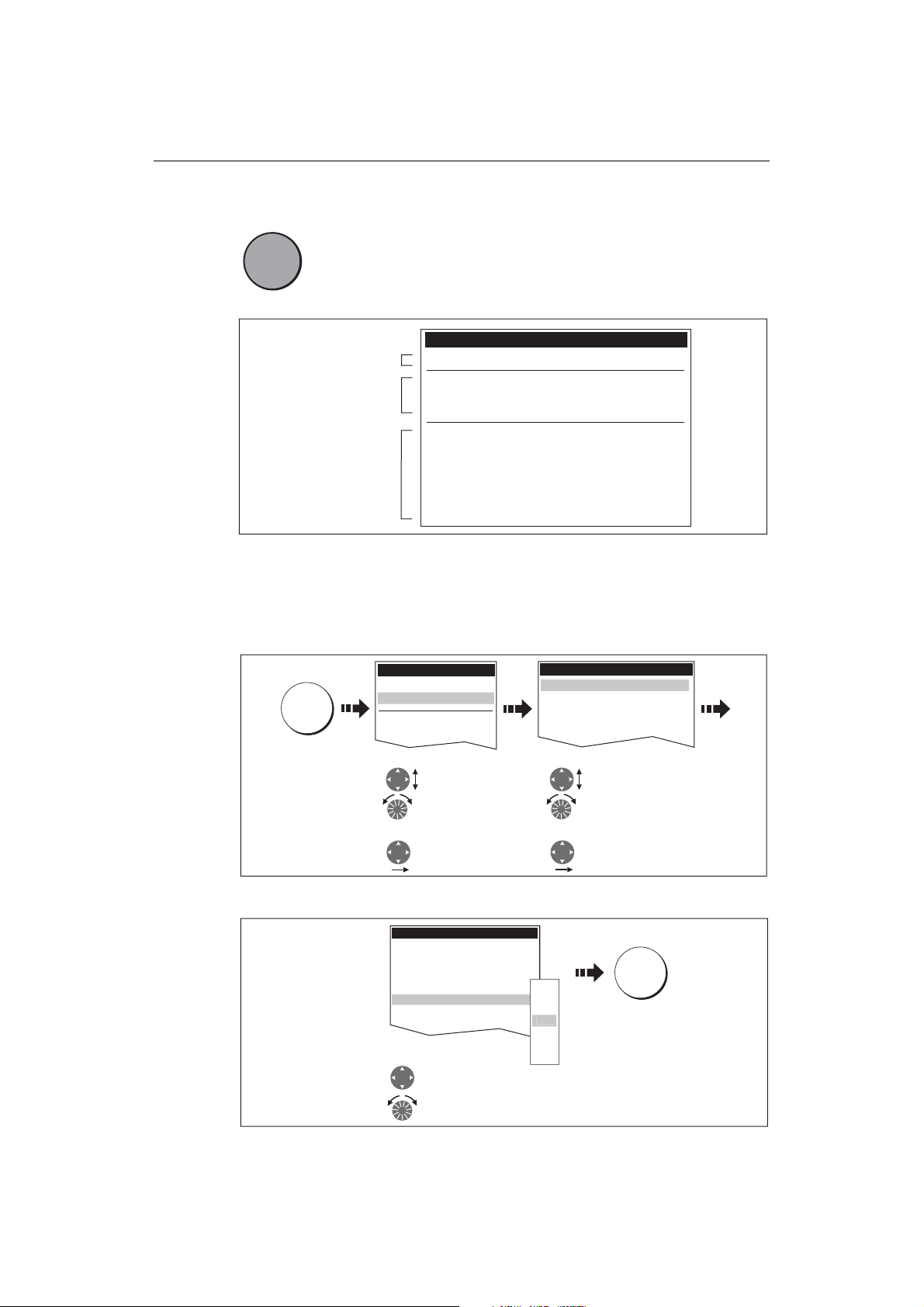
Menus
0
Menus enable you to configure your system to your particular needs.
MENU
MENU
D6582-1
For details of application menus, please refer to the appropriate chapter. For all other
settings, please refer to
To access a menu:
1. Select the appropriate menu and setting:
2. To change the setting:
Whenever the MENU button is pressed, the Setup menu is displayed
containing a list of all the menus available for the active application
together with system wide menus e.g.
Setup
Menus for the active
application
External equipment/
instruments
System-wide menus
MENU
1. Highlight item, using:
2. Select item, using:
Radar Setup ...
GPS Status...
Compass Setup...
AIS Layer Status...
System Setup...
Alarm Setup...
Display Setup...
Databar Set...
Select Page Setup...
System Diagnostics...
Remove CF Card
Chapter 14:System setup and customizing
Setup
Chart Setup...
artography Setup..
GPS Status...
Compass Setup...
Trackpad (up/down)
or
Rotary control
Trackpad (right)
Cartography Setup Menu
Chart Display Detailed
Chart Grid On
Chart Text On
Chart Boundary ON
pot Soundings O
Contour 66
Depth Contour ALL
Nav. Marks ON
Highlight or change value to
new setting, using:
Trackpad (up/down)
or
Rotary control
Cartography Setup Menu
Chart Display Detailed
Chart Grid On
Chart Text On
Chart Boundaries ON
Spot Soundings ON
1. Highlight item, using:
Trackpad (up/down)
or
Rotary control
2. Select item, using:
Trackpad (right)
OFF
7ft
10ft
16f
20ft
33ft
66ft
.
OK
D7370_2
D8500_1
D8501_1
Page 29
Chapter 2: General Operation 13
1
1
a
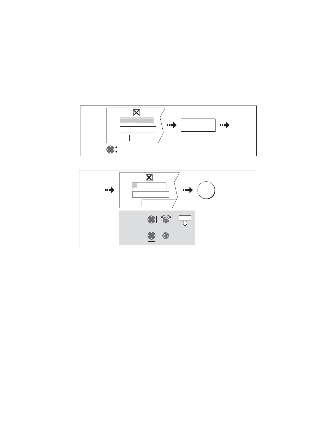
Editing the dialog box information
Dialog boxes enable data to be edited or entered into a list e.g. Edit Waypoint screen.
To edit/enter data into a dialog box:
1. Select the field for editing:
e.g.
Symbol
Name
Waypoint
My Waypoints
Group
Comment
Highlight field to be edited
e.g. waypoint name
2. Edit/enter data and save:
e.g.
Symbol
Name
W
My Waypoints
Group
oint
EDIT NAME
OK
D8502-1
Comment
To change
character or
selection, use:
To move to next
character for
editing, use:
or
,
Turn
or
Press
3. Repeat Steps 1 and 2 if necessary.
Notes: (1) Character text can be entered in upper or lower case. (although the
system is not case sensitive e.g. WAYPOINT 1, Waypoint 1are considered to be the same name).
(2) If you need to use special or accented characters (e.g.
~ ` ´), the
Extended Character Set should be switched to ON in the System
Setup Menu (see page 262).
D8503-1
Page 30
14 E-Series Networked Display Reference Manual
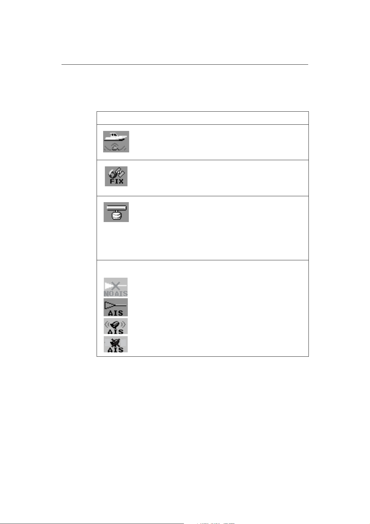
Status icons
The status icons on the data bar confirm whether the appropriate connections to your
E-Series system have been made:
Status icon Description
The boat and fish icon indicates the current status of your fishfinder:
Icon animated - connection to a DSM has been successful.
Icon static - the DSM is connected but not transmitting.
D6892-3
(animated icon)
(static icon)
(static icon)
Icon greyed-out - no DSM is connected.
The satellite icon indicates the current status of your GPS:
FIX - your unit is successfully connected to a GPS receiver.
NO FIX - your unit has been unable to connect to a suitable GPS receiver.
D6893-2
The scanner icon indicates the current status of your radar scanner:
Icon rotates - the scanner is transmitting (TRANSMIT/TX mode).
Icon static - the scanner is powered on but is not currently transmitting
D6894-2
(STANDBY mode).
Icon greyed out - this indicates that the scanner is currently powered
off (OFF mode).
Icon rotates and is then static - a power save mode in which the
scanner powers on/off intermittently (TIMED TRANSMIT mode).
The AIS icon indicates the current status of the AIS function:
AIS unit not available i.e. not connected or off.
AIS unit is switched on and operating.
AIS unit on with active alarms.
AIS unit switched on and operating but dangerous and lost alarm dis-
D8929_1
o
abled.
Note: These icons will also appear when you are in simulator mode.
Page 31

Chapter 2: General Operation 15
/dd/yy
/dd/yy
2.6 Initial setup procedures
When you first use your E-Series Display after it has been commissioned (see
Installation Guide), we recommend that you carry out the following:
• Selecting the data master (Networked E-Series Displays only).
• Set the language, the date and time format and preferred units of measurement.
• Select a page set.
• Select an application page/window.
• Adjust the display lighting.
Note: For full details of all System Setup options, please refer to Chapter 14:System setup and customizing. For application specific set up options, please refer to the appropriate chapter.
Selecting the data master (Networked E-Series only)
When a Networked E-Series system is powered on for the first time, an alarm will
sound and you will be asked to nominate which display is to be the data master. For
details of how to change the data master, please see
page 28
.
Setting the language, date/time format and units of measurement
To adjust the language, date/time format and units of measurement to your preferred
settings:
1. Select the setting:
Setup
MENU
System Setup...
Alarm Setup...
Highlight
System Setup
Enter System
Setup
2. Adjust the setting:
e.g.
Date/Time Setup Menu
ate Format mm
Time Format 12hr
Local Time Offset UTC
or
Change value as
required
3. Repeat this process until you have changed all of these settings.
System Setup Menu
Position Made Lat/Lon...
Date/Time Setup...
Units Setup...
System Integration Setup...
Waypoint Password Setup...
Highlight required
setting
Enter setting
m
dd/mm/yy
OK
D8504-1
D8505-1
Page 32

16 E-Series Networked Display Reference Manual
Selecting a page set
Your Display has four pre-configured page sets and one empty set for you to choose
from. The applications configured in a page set is a local setting and will therefore only
affect the individual display on which you are working.
PAGE OK
Press &
hold
Highlight appropriate pre-configured page set
Note: Alternatively, you can access the Select Page Set screen via MENU.
If none of the pre-configured page sets meet your particular requirements and/or you
intend to use the engine monitor, weather or video application, refer to the Setup and
Customizing chapter for details of how to customize both the layout and the
application appearing in each window.
D8511-1
Selecting an application page
Once you have selected the appropriate page set (see previous section), choose the
application page that you wish to use:
PAGE
Press until required
page displayed
PAGE
Or:
Press soft key of
required page
D8512-1
Page 33

Chapter 2: General Operation 17
Selecting an application window
When the selected page has more than one window, the window that is currently
active will be bordered in red e.g.
Active window
highlighted
Soft keys
associated with
active window
Changing the active window
To change the active highlight to other windows on the page and display the
associated soft keys:
Active
window
e.g.
ACTIVE
Active
window
D8516_1
Press to move
active window
Multiple to single window
To make the active window full-screen when multiple windows are being displayed:
ACTIVE
Press and
Multiple windows Single window
hold
Single to multiple windows
To return to multiple windows:
ACTIVE
Multiple windowsSingle window
D8513-1
D8514-1
D8515_1
Page 34

18 E-Series Networked Display Reference Manual
Adjusting the display lighting
The display has two distinct color palettes, for day and night operation. You can also
manually adjust the backlight level.
Note: The display lighting is a local setting and will therefore only affect the individual
display on which you are working.
Day/night operation
To select the day/night mode of operation:
PALETTE
DAY NIGHT
Toggle as required
OK
The display saves the current palette when the unit is powered off. If the palette was set
to NIGHT when it was last used, and you then power on in bright sunlight, it may be
difficult to see the screen. Reset the palette to DAY to return to normal daytime
lighting.
Backlight level
To adjust the backlight level when in day or night operation mode:
Backlight Level
OK
Change the level as required
D6802-3
D8517_1
Page 35

Chapter 2: General Operation 19
2.7 Using CompactFlash cards
Cautions
CAUTION: CompactFlash Card Installation
When installing CompactFlash cards ensure that the card is fitted the correct
way around. DO NOT try to force the card into position as this may result in
irreparable damage to the card.
CAUTION: Water Ingress
To prevent the ingress of water and consequent damage to the display,
ensure that the chart card door is firmly closed at all times. This can be
confirmed by an audible click.
CAUTION: Card Removal
DO NOT use a metallic instrument such as a screwdriver or pliers to help you
remove a card, as doing this can cause irreparable damage.
CAUTION: Card writing
CompactFlash cards can be damaged if they are removed from the unit
during either a read or write operation. A warning is displayed during write
operations. The unit is continually reading the card. It is therefore essential
that before removing the card you follow the correct procedure to stop
access to the card.
What are CompactFlash cards used for?
CompactFlash cards enable you to get the most from your display. Their uses include:
• Detailed cartographic information
Obtain detailed cartographic information of the area that you navigate using Navionics® chart cards. To check the current availability of Navionics chart card types,
please visit www.navionics.com or www.navionics.it.
The amount of cartographic detail shown varies for different areas and for different scales. The chart scale in use is indicated in the status bar - the number represents the distance in nautical miles from the top of the chart window to the
bottom of the chart window.
• Archiving
To archive waypoints, routes and tracks.
• Saving
To save waypoint, route and track data for use by other equipment e.g. a PC.
You can remove and insert cards while a chart is displayed provided that you follow the
correct procedure (see
chartplotter redraws the screen; for example, when you pan outside the current area,
or use the RANGE button to change the chart scale.
Note: In a networked system, cartographic data is available to any E-Series display
connected on the SeaTalk High Speed network. However, the ARCHIVE and TRANSFER
functions only operate with the card inserted in the display at which you are working.
page 20
). The chart information is retained on-screen until the
Page 36

20 E-Series Networked Display Reference Manual
Inserting a card
To insert a card, refer to the illustration and:
1. Check that you are using the correct type of card (see
beginning of this manual
).
Important Information
, at the
2. Open the chart card door, located on the front left of the display.
3. Insert the card as shown, with the lip of the card facing inwards. It should position
easily. If it does not, DO NOT force it, check the direction in which the lip is facing.
4. Gently press the card home.
5. To prevent the ingress of water and consequent damage, close the chart card door
and press firmly until a click is heard.
Narrow
Groove
Lip
Removing a card
...with the unit powered on
1. Select the CF Card Removal function:
MENU
IMPORTANT:
If you try to remove a card without accessing the setup menu, a blue screen and
warning message is displayed and the unit must be restarted. In an E-series networked system, where any display may be accessing the card, this message
System Diagnostics...
Remove CF Card
Setup
Highlight
Remove CF Card
Select Remove
CF Card
CF Card Removal
You may now safely remove your
compact flash card.
Press OK or CANCEL when finished.
D7215_2
D8518-1
Page 37

Chapter 2: General Operation 21
appears on all displays in the network. All displays will therefore need to be
restarted individually.
You must only remove the card while the CF Card Removal message is displayed.
Once the message is closed, the card should no longer be removed.
2. Open the chart card door.
3. Grip the card and pull to remove it from its slot.
4. To prevent the ingress of water and consequent damage, close the chart card door
and press firmly until a click is heard.
5. Press OK.
...with the unit powered down
1. Open the chart card door.
2. Grip the card and pull to remove it from its slot.
3. To prevent the ingress of water and consequent damage, close the chart card door
and press firmly until a click is heard.
2.8 Managing data
This section explains how you can manage the data contained in your E-Series and
includes the following:
• Writing/retrieving to a CF card.
• Erasing information from a card.
• Erasing information from your system.
• Transferring information to/from a PC.
• Password protection.
Writing/retrieving data to a CompactFlash card
Your display can save up to 1,200 waypoints, 150 routes and 10 tracks in data base
lists. Once this number is reached you will need to archive data to a CompactFlash card
for safe-keeping or retrieval at a later date. Alternatively, you can transfer data to
another instrument or PC using SeaTalk
also receive waypoints, routes and tracks from a PC, other SeaTalk
NMEA instruments (see
page 25
Note: In a networked E-Series system, you archive to and retrieve data from the CompactFlash card in the display on which you are working.
hs
or NMEA. When navigation is active, you can
hs
, SeaTalk and
).
Page 38

22 E-Series Networked Display Reference Manual
1
Saving information to a card
Important:
Raymarine strongly recommend that you save data to a separate CompactFlash card
and not to a Navionics card containing cartography.
1. Insert card and select the SAVE TO CARD function:
DATA
ARCHIVE AND
Insert card
2. Select list containing data for saving:
SELECT LIST
WPT RTE TRK
Toggle to required
list
3. Define data for saving
To save all items in list to card:
SAVE ALL
Or
To save individual items:
e.g.
ROUTE LIST
oute 1
Route 2
Route 3
e.g.
SAVE ROUTE
TRANSFER
e.g.
ROUTE LIST
oute
Route 2
Route 3
Contents for selected list displayed
SAVE TO CARD
D8070_1
D8655_1
Save Route
Follow on-screen instructions
to remove card
Highlight item
for saving
D8520_1
Page 39

Chapter 2: General Operation 23
1
1
Retrieving information from a card
1. Insert card and select the RETRIEVE FROM CARD function:
DATA
Insert card
2. Select required list:
SELECT LIST
WPT RTE TRK
Toggle to required
list
3. Define data to be retrieved:
To retrieve all selected database items:
RETRIEVE ALL
Or
To retrieve individual items:
e.g.
ROUTE LIST
Route
Route 2
Route 3
ARCHIVE AND
TRANSFER
e.g.
RETRIEVE ROUTE
RETRIEVE FROM
CARD
ROUTE LIST
oute
Route 2
Route 3
Contents for selected list displayed
Retrieve Route
Follow on-screen instructions
D9094_1
D8655_1
Highlight item for
retrieving
D8656_1
If whilst retrieving information a selection is already found to exist on the system, a
warning message will appear.
The soft keys will change to give you the options of retrieving as new, replacing or
cancelling the retrieving process
Page 40

24 E-Series Networked Display Reference Manual
1
1
Erasing information from a card
If you wish to remove information from a card, for example you no longer need it, or
the card is full, it can be erased by using the ERASE FROM CARD soft keys. A message
will be displayed on screen asking you to confirm that you want to delete the item(s),
before it takes place.
1. Insert the card and select the ERASE FROM CARD function:
DATA
Insert card
2. Select the required list:
SELECT LIST
WPT RTE TRK
Toggle to required
list
3. Define data to be deleted:
To delete all items:
ERASE ALL
Or
To delete individual items:
e.g.
ROUTE LIST
Route 2
Route 3
ARCHIVE AND
TRANSFER
e.g.
ERASE ROUTE
ERASE FROM
CARD
ROUTE LIST
oute
Route 2
Route 3
Contents for selected list displayed
YES
D8168_1
D8655_1
Highlight item for
deleting
D8657_1
Page 41

Chapter 2: General Operation 25
Sending and receiving information using a PC
You can transfer and retrieve waypoints or routes to and from another instrument or
PC using NMEA or SeaTalk
With a RayTech 6.0’s planner you can transfer waypoints and routes via a CF memory
card. Such transfers require that the PC be connected to the display’s NMEA port via a
serial data cable. RayTech 6.0 will transfer waypoints and routes via SeaTalk
To transfer or receive information:
1. Select the transfer on NMEA option:
hs
.
hs
.
DATA
ARCHIVE AND
TRANSFER
TRANSFER ON
NMEA...
2. Press the appropriate soft key to send or receive NMEA:
SEND WPTS ON
NMEA
SEND RTES ON
NMEA
RECEIVE ON NMEA
Note: If you wish to stop the transfer at any point, press
STOP TRANSFER
STOP TRANSFER.
3. When transfer is complete, STOP TRANSFER greys out and the soft keys reappear.
Password protecting your waypoints
If required, you can prevent access to, modification and sight of your waypoint and
route databases and functions by means of a password.
Password confirmation
When Password Protection is enabled and you are attempting to access a password
protected function for the first time during a power-cycle, the system will request
confirmation of your password before you can:
• Access WPTS key functions. This does not affect the operation of the MOB function.
• Access ROUTES soft key functions.
D8638_1
D6808-2
• Create a route from a track. All other track functions are unaffected.
• Archive or transfer any waypoints.
• Enter the Waypoint Password Setup menu.
Note:
Once you have provided a password to the system, it must be entered to access
the Password Setup sub-menu, regardless of the whether Password Protection is set to
ON or OFF.
Disabled data/functions
When Password Protection is ON and you have not entered a password you will be
unable to:
Page 42

26 E-Series Networked Display Reference Manual
d
• View details of waypoint and route databases.
• Edit waypoints or routes.
• Goto an existing waypoint.
• Follow a route.
• View waypoints on screen (even when the SHOW/HIDE status is set to SHOW).
• View waypoint names on screen (even when WAYPOINT NAME is set to ON).
All other options including GOTO CURSOR are unaffected.
Setting up a password
To setup a password:
1. Select Waypoint Password Setup:
MENU
Setup
Radar Setup...
GPS Status...
Compass Setup...
System Setup...
System Setup Menu
System Integration
Waypoint Password Setup
Highlight required
System Setup Menu
Select System Setup
Menu
Highlight Waypoint
Password Setup
Select Waypoint
Password Setup
2. Change the Enable Password status to ON, read and accept the warning:
Setting Password Protection
required a password to access
your waypoint and route
databases.
If you forget your password you
Waypoint Password Setup
Enable Passwor
Change Password...
N
OK
Select Enable
Password
Select ON.
will lose your waypoints and
routes
Raymarine recommends that you
archive your waypoints and
routes
YES
Read and accept
the warning
3. Enter a password and confirm it:
e.g.
Edit Password
Password:
Confirm Password:
Choose a word that will help you
to remember your password
and/or:
Hint:
Enter a password
(1-16 characters)
Carrot
OK
e.g.
Edit Password
Password:
Confirm Password:
Choose a word that will help you
to remember your password
and/or:
Hint:
Repeat to confirm
the password
Carrot
Carrot
D8954_1
D8962_1
OK
D8957_1
Note:
The password is case sensitive.
Page 43

Chapter 2: General Operation 27
F
4. Add a hint, to help you to remember your password (optional):
e.g.
Edit Password
Password:
Confirm Password:
Choose a word that will help you
to remember your password
Hint:
Carrot
Carrot
Rabbit
OK
Your password has been accepted.
If you continue your waypoints
and routes will be protected.
If you forget your password you
will lose your waypoints and
routes
Raymarine recommends that you
archive your waypoints and routes
Do you want to continue?
and/or:
Add a hint word
(0-16 characters)
YES
Read and accept the warning
The password is now set and protection enabled although access to the waypoint and
route functions remains available until you restart your system.
Note:
If required, this password can be changed by selecting the Change Password
option on the Waypoint Password Setup Menu.
Enabling/disabling password protection
Once you have set up a password on your system (see previous section) you will need
to key in this password whenever you want to change the status of the password
protection feature.
To enable/disable password protection:
1. Select Waypoint Password Setup:
Setup
MENU
Radar Setup...
GPS Status...
Compass Setup...
System Setup...
Highlight required
System Setup Menu
Select System Setup
Menu
2. Enter your password ensuring that the appropriate upper or lower case characters
are used and then enable/disable the password protection, as required.
Enter Password
Password:
Carrot
Enter password
OK OK
Waypoint Password Setup
Enable Password OF
Change Password...
System Setup Menu
System Integration
Waypoint Password Setup
Highlight Waypoint
Password Setup
Select Waypoint
Password Setup.
Select Enable Password
D8958_1
D8960_1
Select OFF
D8961_1
Important: If you enter an invalid password more than twice within one power cycle
the system shall display the hint. There is no limit to the number of attempts to enter a
valid password but if you forget your password, you will need to perform a Settings
Page 44

28 E-Series Networked Display Reference Manual
and Data Reset (see
page 229
) which will erase all waypoints in the unit’s memory.
Raymarine strongly recommend therefore that you regularly back-up your waypoints,
routes and tracks to a CF memory card.
2.9 Operating a networked E-Series Display
What does a networked system do?
If you have connected two or more E-Series Displays (via either a crossover coupler or
SeaTalk High Speed Network Switch), data is transferred across the network enabling
you to input, view and maintain applications and data across all your Displays
irrespective of the Display from which the data originated (excepting Video Input).
To ensure that the latest data i.e. SeaTalk data and waypoints, routes and tracks
databases is available at all displays, the system needs one display to be designated as
the data master.
Controlling a network
System data including user-created databases are managed by the data master. The
display that has been installed and nominated as the master, should always be
switched on (preferably first). The master display will copy its database to all other
Displays that are switched on, each time it detects a change.
If the system does not detect a master, either because it is not switched on or because
a master has not been selected, an alarm will sound and you will be prompted to select
a master display.
Note: The data master copies its database to all other displays in the system. To prevent loss of data when adding displays, or changing the master, ensure that you select
the appropriate display as the master. You can archive the database onto a CompactFlash card and retrieve it later.
Changing the master display
On the display that you wish to nominate as the master:
1. Display the System Setup menu:
Setup
MENU
2. Select the System Integration then Data Master option:
Radar Setup...
GPS Status...
Compass Setup...
System Setup...
Highlight System Setup
Enter System Setup
D8652_1
Page 45

Chapter 2: General Operation 29
yg
Setup.....
.
r
yg
Setup.....
.
r
System Setup Menu
System Setup Menu
Postion Mode
Postion Mode
TD Setup
TD Setup
Simulator
Simulator
Bearing Mode
Bearing Mode
MOB Data Type
MOB Data Type
Variation Source
Variation Source
Manual Variation
Manual Variation
Langauge
Langauge
Extended Charactor set
Extended Charactor set
Ground Trip Reset.....
Ground Trip Reset.....
Settings Reset......
Settings Reset......
Settings and Data Reset.....
Settings and Data Reset.....
Date/Time Setup......
Date/Time Setup......
stem integration....
stem integration....
Highlight System
Highlight System
Integration
Integration
Enter System Integration
Enter System Integration
Lat/Long
Lat/Long
ON
ON
ON
ON
Position
Position
Auto (01oE)
Auto (01oE)
00oE
00oE
English (US)
English (US)
OFF
OFF
ON
ON
Enabled
Enabled
ON
ON
OFF
OFF
System Integration Setup Menu
System Integration Setup Menu
DSC Message
DSC Message
Seatalk Alarms
Seatalk Alarms
ata Maste
ata Maste
Brigdge NMEA Headings
Brigdge NMEA Headings
Highlight Data Master
Highlight Data Master
Enter Data Master
Enter Data Master
ON
ON
Any such changes that you make to the nominated master will be saved when you
power off.
Functions only affecting the display in use
The majority of functions, settings, additions and changes that you perform on a single
Display are ‘seen’ by all other Displays connected to your network. There are however
some local settings that will only affect the individual display on which you are
working.
D8653_1
D8653_1
These local settings are summarized as follows:
• Page set - selecting a set, name and applications configuration.
• Power on/off key (including Day/night setting).
•The ACTIVE window.
• The displayed panel in the digital data or engine monitoring application.
• Radar and Fishfinder presentation settings.
• Radar VRMs, EBLs and Wakes.
• Chart presentation settings when the Chart View is set to LOCAL.
• Show/hide waypoints, routes or tracks.
• Fishfinder Setup Menu options (top half of menu only).
• Video, Databar and Display Setup Menus.
• Databar on/off and configuration.
•Ruler settings.
Page 46

30 E-Series Networked Display Reference Manual
2.10Emergencies and warnings
You can use your E-Series display to mark the position of a man overboard or to sound
an alarm when a particular situation occurs e.g when a depth limit is reached, a
specified period of time has elapsed etc.
Man Overboard (MOB)
Marking a MOB
WPTS
MOB
Press and hold
until alarm sounds
If you lose a person or object overboard, and need to return to the location, you should
use the Man Overboard (MOB) function immediately. The MOB function can be used
whilst any application is in use and is activated by either pressing and holding the
WPTS/MOB key for three seconds, or by a MOB message being received from other
equipment on the SeaTalk system.
D6652-3
When a MOB is activated the following is initiated automatically:
• Alarm - the MOB alarm is triggered (Morse --- every 30 seconds)
• Waypoint - a MOB waypoint is placed at your current position.
D9101_1
• Positional information - the bearing, range and vessel position are displayed in
the data bar. These are calculated according to the MOB data type set in the System
SetUp (see
page 262
). Assuming that your boat and the MOB are subject to the
same tide and wind effects, dead reckoning normally gives a more accurate course.
• Radar range change - if radar is transmitting, the system changes the radar
range to
1
/8 nm.
• Active navigation is suspended - Navigation to any active waypoint is sus-
pended and any existing navigation function is cancelled. No further GOTO or route
functions are selectable whilst the MOB function is active.
• Autorange motion mode - If radar/chart synchronisation is set to OFF (see
page 84
), the chart application changes the motion mode to Autorange. This displays the largest possible scale of chart that will include both the target waypoint
(MOB symbol) and your on-screen vessel.
• Other equipment - other Raymarine equipment acknowledges the MOB.
• Current position to MOB position - as your vessel moves away from the MOB
position, a dotted line is displayed from your current position to the MOB position.
Note: To obtain a MOB position, you need either position data from a GPS (or equivalent device) or heading and speed data.
Page 47

Chapter 2: General Operation 31
Silencing a MOB
To temporarily silence the alarm from a MOB, press any key on any instrument on the
SeaTalk system. After approximately 10 seconds the alarm will sound once more if the
state of MOB is still active.
Silencing an alarm will not deactivate or clear the MOB state.
Clearing a MOB
To clear a MOB and its data:
Once cleared, your chart and radar
applications will return to the motion
WPTS
MOB
Press and hold
for 4 seconds
mode that applied prior to the MOB
alarm and the GOTO and route functions
will once more be available.
Note: Alternately if you have a MOB key-
D8231_1
pad fitted, press and hold the MOB key.
Alarms
You get warning of a hazard or a particular situation via in-built alarms which are
generated for the system as a whole or for individual applications. When an alarm
sounds, a message box is displayed explaining the cause of the alarm.
You can specify what alarms will operate and the parameters within which they will
sound, via the Alarm Setup Menu (see
page 265
).
Cancelling alarms
Display alarms
By pressing the ACKNOWLEDGE soft key, the alarm is silenced and any message box is
cleared. If the alarm has been generated by the chartplotter, the appropriate action is
taken. For example, following an arrival alarm, the next route leg is activated.
Please note:
• Although you can change the configuration of the arrival alarm, it cannot be turned
off.
• To cancel a MOB alarm, press and hold the WPTS/MOB until the MOB symbol disappears from the screen.
• If an anchor alarm is silenced, but the alarm condition persists, the alarm is
repeated every 30 seconds
External alarms
If an instrument that is connected to the display on SeaTalk generates alarms, these
will sound on your E-Series display accompanied by a pop-up message box. You can
cancel these alarms by pressing the ACKNOWLEDGE soft key. The alarm will be
silenced, but no other action will be taken by the E-Series display.
Page 48

32 E-Series Networked Display Reference Manual
Page 49

Chapter 3: Working with Waypoints 33
Chapter 3: Working with Waypoints
This chapter gives details of how to place, edit, manage and navigate to a waypoint.
3.1 What is a waypoint?
A waypoint is a position marked on a chart, radar or fishfinder window to indicate a
site (for fishing, diving etc.) or as a place to navigate to. By default, all waypoints are
indicated on screen by a waypoint symbol you wish. You can also select an alternative symbol to be used as the default for newly
created waypoints.
Waypoint symbols
x. This symbol can however be changed if
Note:
For details of how to change the symbol, please refer to page 39.
Waypoints are a core feature of the E-series display. They can be created in any
application and are displayed on the radar, chart and fishfinder windows. A series of
waypoints can be combined together to form a route. If you have networked several ESeries Displays, any waypoints that are created on one display are ‘seen’ by all the
other displays.
The details of all waypoints, irrespective of the application they were created in, are
stored in a dedicated waypoint list which will hold up to 1200 waypoints. All waypoints
are by default, placed in the MY WAYPOINTS group. If required, you can create new
groups and change the default group. If necessary, waypoints can be archived to a
CompactFlash card or transferred to another NMEA compatible instrument. If the
system receives an active waypoint over SeaTalk or NMEA, it is displayed but cannot be
edited.
If required, you can prevent access to, modification and sight of your waypoint and
route databases and functions by means of a password. For more information see
page 25
Note:
.
You can only archive and transfer waypoints to a CompactFlash card/NMEA link
installed at the display on which you are working.
D8696_1
Page 50

34 E-Series Networked Display Reference Manual
3.2 How are waypoints represented?
Waypoints on 2D Chart and Radar windows
On 2D chart and radar windows, a waypoint is represented when it is both active
(displayed in a box) and inactive (no box) i.e.
Waypoint 1
Default waypoint
Active waypoint
Alternative symbol
Waypoints on 3D Chart and CDI windows
On 3D chart and CDI windows, a waypoint is represented only when it is active
(displayed in a box).
Waypoints on Fishfinder windows
When a waypoint is created it is represented on fishfinder windows, by a vertical line
labelled WPT. This symbology cannot be changed.
WPT
D8694_1
D8698_1
WPT
WPT
Note:
A waypoint can be placed when a Weather application window is active but it
D8697_1
will not be seen in the weather window.
Page 51

Chapter 3: Working with Waypoints 35
3.3 Placing a waypoint
A waypoint can be placed at:
• The cursor position.
• Your vessel’s position.
• At a position of your choosing (using lat/lon or Loran TD coordinates between 80
N/S).
When you are placing a waypoint, you can either accept the default or customize its
details. For more information see
Once a waypoint has been placed, you can view its details and edit them (if necessary).
For more information, see
... at the cursor
page 37
page 38
and
page 38
.
.
OK
0
WPTS
MOB
Move cursor to
required position
for waypoint
WAYPOINT AT
CURSOR
Or
Wait 4 secs
Accepts default
... at your vessel’s position
WPTS
MOB
WPTS
MOB
WAYPOINT AT
Or
x2
VESSEL
OK
Or
Wait 4 secs
Accepts default
If the system cannot determine your position, a warning is displayed and the waypoint
is not placed.
... at a known position
WPTS
MOB
WAYPOINT AT
LAT/LON...
Place Waypoint
Position:
01
50'.838N
o
06'.331W
OK
D7457-2
D7458_2
Enter position x 2
D7459_2
Page 52

36 E-Series Networked Display Reference Manual
3.4 Navigating to a waypoint
This section explains how to start and stop navigating to a waypoint. When you
navigate to a waypoint or to the cursor position, the data is sent on NMEA 0183 and
SeaTalk and can be used by an autopilot, if connected. For more information on
navigation, see
page 89
.
Start navigating to a waypoint
You can navigate to a waypoint using the cursor, via the
WPTS MOB button or by selecting the GOTO option.
Once navigation is active, the waypoint symbol is
surrounded by a box and a dashed line appears between
your boat and the waypoint.
If required you can display navigation details for the
D8285_1
active waypoint in the data bar (see
...using the cursor
To navigate to a waypoint using the cursor, when a chart or radar application is active:
GO TO WAYPOINT
WPT
Position cursor over
waypoint to go to.
...via the WPTS MOB button
To navigate to a waypoint using the WPTS/MOB button when any application is active:
page 259
).
D7461_4
WPTS/
MOB
GOTO WAYPOINT
OPTIONS ...
Waypoint List
Select required waypoint
GOTO WAYPOINT
.... by selecting the GOTO option
You can navigate to a waypoint using the GOTO option when a 2D or 3D chart
application is active and the top level chart soft keys are displayed:
GOTO WAYPOINT
GO TO ...
OPTIONS...
Or
GOTO CURSOR
Waypoint List
GOTO WAYPOINT
Select required waypoint
D6559-3
2
3_
0
5
7
D
Page 53

Chapter 3: Working with Waypoints 37
Stop navigating to a waypoint
If at any time you wish to stop navigating towards the selected waypoint:
WPTS/
MOB
Or:
WPT
Position cursor over
active waypoint.
GOTO WAYPOINT
WPTS/
OPTIONS...
MOB
STOP GOTO
Position cursor over
active waypoint.
GOTO WAYPOINT
OPTIONS...
Or
D7505-1
WPT
STOP GOTO
Once navigation is no longer active, the waypoint symbol returns to its normal
unboxed state and the dashed line between your boat and the waypoint is removed.
3.5 Viewing waypoint information
You can view the details of any waypoint that you have placed, by either selecting it
with the cursor (in radar and chart windows) or by selecting it on the waypoint list.
Once you are viewing a waypoint’s details, a variety of editing and managing options
are available.
You can also display navigation details for the active waypoint in the data bar (see
page 259
).
STOP GOTO
STOP GOTO
D7505-2
...using the cursor
To view the details of a waypoint that is not active.
Edit Waypoint
EDIT WAYPOINT
OK
WPT
Position cursor
over waypoint
Note:
Details of the waypoint that you are currently navigating to, can be accessed via
Waypoint details displayed
To exit waypoint list
the waypoint list as described below.
...using the waypoint list
The waypoint list shows all the waypoints that have been placed (including the active
one), and displays details of the selected waypoint:
Temperature and depth are only captured (if available) for waypoints placed at
Note:
your vessel’s position.
D7506_2
Page 54

38 E-Series Networked Display Reference Manual
To access the waypoint list:
D6560-2
WPTS/
MOB
REVIEW AND EDIT
WAYPOINTS...
3.6 Editing a waypoint
Once a waypoint has been placed it can be edited in a variety of ways. You can:
• Change the waypoint details - name, symbol, group or add a comment.
• Move a waypoint.
•Erase a waypoint.
• Change the default symbol and group of newly placed waypoints.
Waypoint List
Select required waypoint
OK
To exit waypoint list
D7507-2
D6561-1
D6561-2
Page 55

Chapter 3: Working with Waypoints 39
Changing waypoint details
When a waypoint is created it is assigned a default name, symbol and group. You can
change these details to suit your needs and add a comment if required. This is
particularly useful when you are managing large numbers of waypoints.
To change the details of a waypoint:
1. Select the detail you wish to edit:
WPT
Or
Waypoint List
Select required waypoint with
cursor or via waypoint list
VIEW AND EDIT
DETAILS
Edit Waypoint
Highlight field
for changing
2. Edit the selected detail:
Repeat for other fields, if necessary
e.g.
EDIT SYMBOL
Soft key reflects
highlighted field
Note:
If you make a mistake whilst editing, press CANCEL.
Edit Waypoint
Edit details as required using:
Soft key
and/or
,
OK
To save
Moving a waypoint
You can move any waypoint (except the active one) to a new position. There are two
methods of moving a waypoint:
OK
To save and
exit editing
D8286-1
D8287-1
... by entering new coordinates
If you know the new co-ordinates, bearing or range for the particular waypoint, you
can enter this information by editing the waypoint as described in the previous section.
... by dragging the waypoint to a new position
WPT
MOVE WAYPOINT
WPT
Select waypoint
for moving
Note:
To abandon the move, press CANCEL.
WPT
PLACE WAYPOINT
Drag waypoint
to new location
D8288-1
Page 56

40 E-Series Networked Display Reference Manual
CAUTION:
It is possible to move waypoints that are used in routes. In such instances, the
stored route will include the Waypoint in its new position. Ensure that this
does not present a navigation hazard.
Erasing a waypoint(s)
You can erase any waypoint on the system (including groups of waypoints) except:
• The active waypoint or
• Any waypoint used in a route.
Notes: (1)
If a route is hidden its waypoints can still be displayed. If you attempt to
erase a waypoint from a hidden route, a warning message will be displayed.
(2)
For details of erasing groups of waypoints, see page 45.
Erasing an individual waypoint
You can erase individual waypoints on screen or via the waypoint list.
...using the cursor
ERASE WAYPOINT
WPT
Select waypoint
for erasing
... using the waypoint list
1. Select the waypoint for erasing from the waypoint list:
WPTS
MOB
REVIEW AND EDIT
WAYPOINTS...
Waypoint List
YES
Confirm the pop-up
message
D8289-2
2. Erase the selected waypoint:
ERASE WAYPOINT
YES
Select waypoint
for erasing
D8843_1
OK
D8844_)
Page 57

Chapter 3: Working with Waypoints 41
W
Erasing all waypoints
If you need to erase all your waypoints, you can use the ARCHIVE & TRANSFER soft
keys:
1. Select the ERASE FROM SYSTEM option and the appropriate list:
DATA
ARCHIVE AND
TRANSFER
ERASE FROM
SYSTEM...
SELECT LIST
PT
Select the WPT list
2. Erase all waypoints:
System Waypoint List
Waypoint Group 1
Waypoint Group 2
Waypoint Group 3
ERASE ALL
WAYPOINTS
YES
System waypoint list
displayed
Changing the default symbol or group
When you add a waypoint to your system it is assigned to the default group and given
the default symbol:
Default Symbol
My Waypoints
If these are not suitable, you can select an alternative symbol and group to be the
default. For an alternative group to be selected for the default, it must first be created see
page 43
.
Default Group
D6658-2
D8716-1
D8851_1
1. Select either the default symbol or group:
WPTS
MOB
REVIEW AND EDIT
WAYPOINTS...
SET DEFAULT SYM
2. Change the symbol or group default:
Symbol
EDIT DEFAULT
& GROUP...
Or
Select required
default symbol
SET UP DEFAULT
YMB
Toggle to required option.
Default displayed.
OK
To save
D8290-1
D8291-1
Page 58

42 E-Series Networked Display Reference Manual
e
Group List
Group
Note:
To abandon the symbol or group default change, press CANCEL.
EDIT DEFAULT
Select required
default group
OK
To save
3.7 Sorting the waypoint list
If your system contains a large number of waypoints, you can sort your waypoint list to
make i t easier to locate a particular waypoint.
The waypoint list can be sorted by:
• Name (default)
• Range (closest first)
•Symbol
• Group name
•Date
D9055-1
• Comment
•Depth
To sort the waypoint list:
SORT LIST
SELECT SORT
OPTION
3.8 Organising waypoints into groups
Provided that you have not changed the default group, all waypoints are automatically
placed in the default “My Waypoints” group when they are created. In order to make
your waypoints easier to manage, you can organize them into groups of your choice.
When fishing, for example, you may only wish to see the waypoints that indicate good
fishing sites. Other waypoints, say, for racing, would be superfluous at this time.
A waypoint cannot be placed in multiple groups
Note:
Displaying the waypoint group list
To display the group list with its options:
SORT LIST BY
Range
Order by:
Name
Range
Symbol
Dat
Depth
Select sort method
OK
Save
D8292-1
Page 59

Chapter 3: Working with Waypoints 43
s
e.g.
GROUP LIST
WPTS/
MOB
REVIEW AND EDIT
WAYPOINTS ...
WAYPOINT
GROUPS ...
Deep fishing
Shallow fishing
Reef fishing
You can now make a new waypoint group, or erase, move or rename existing groups.
Making a new waypoint group
To create a new waypoint group:
1. Display the group list (see above).
2. You can now either:
Make a new group and accept the default name:
MAKE NEW
GROUP...
Or
Make a new group and customise the name:
MAKE NEW
GROUP...
MAKE NEW
OK
GROUP...
MAKE NEW
GROUP...
EDIT GROUP
NAME
D8293_1
OK
OK
D8293_1
NEW WAYPOINT GROUP
OK
D6885-3
Moving waypoints between groups
Waypoints can be easily moved between groups:
1. Display the group list (see
page 42
2. Display the MOVE BETWEEN GROUPS option:
MOVE BETWEEN
GROUPS...
3. Determine the group that contains the waypoint to be moved:
GROUP LIST
SELECT GROUP A
Waypoint
Deep fishing
Shallow fishing
Reef fishing
Select group
containing waypoint
to be moved.
).
MOVE BETWEEN GROUPS
GROUP A GROUP B
My Waypoints
Waypoint 1
Waypoint 2
Waypoint 3
OK
Edit name
GROUP LIST
Fishing
MOVE BETWEEN GROUPS
GROUP A
My Waypoints
Waypoint 1
Waypoint 2
Waypoint 3
Waypoints in selected group
listed.
Save
D8293_2
D8295_1
D8297_1
Page 60

44 E-Series Networked Display Reference Manual
3
4. Determine the group that the waypoint is to be moved to as follows:
MOVE BETWEEN GROUPS
GROUP A GROUP B
My Waypoints
Waypoint 1
Waypoint 2
Waypoint 3
GROUP LIST
Fishing
SELECT GROUP B
GROUP LIST
My Waypoints
Deep fishing
Shallow fishing
Reef fishing
OK
Move control to
Group B
5. Select waypoint to be moved:
Repeat until all changes made
MOVE BETWEEN GROUPS
GROUP A GROUP B
My Waypoints
Waypoint 1
Waypoint 2
Waypoint
GROUP LIST
Fishing
Move control to Group A.
Select required waypoint.
Note:
Alternatively, waypoints can be moved from Group B to Group A if required. The
soft keys reflect this accordingly.
Renaming an existing group
You can change the name of an existing waypoint group:
1. Display the group list (see
2. Select the group for renaming:
page 42
).
MOVE WAYPOINT
FROM A TO B
Select group to
add waypoint to
D8298_1
OK
D8299_1
GROUP LIST
My Waypoints
Deep fishing
Shallow fishing
Reef fishing
RENAME GROUP...
Select required
group
3. Edit the selected group name:
EDIT GROUP
NAME
Note:
To revert to the original name whilst editing, press CANCEL.
NEW WAYPOINT
Edit name
OK
Save new
name
D8300_1
D8301_1
Page 61

Chapter 3: Working with Waypoints 45
Erasing a group
You can erase any waypoint group from the system except the group containing the
active waypoint.
When a waypoint group is erased, the group name together with all of the waypoints
in that group are erased from the system with the exception of:
• ‘My Waypoints’ - the waypoints contained within this group are deleted but the
group name remains.
• Waypoints used in routes within your system.
You should therefore ensure that any individual waypoints that you want to keep
(which are not part of a route), are moved before their group is erased.
1. Display the group list (see
page 42
).
2. Select and erase the group:
GROUP LIST
My Waypoints
Deep fishing
Shallow fishing
Reef fishing
Highlight page
set for editing
Note:
Waypoint groups can also be erased via the ARCHIVE AND TRANSFER function
ERASE GROUP... YES
(page 41). For details of how to erase waypoint groups from a card, see page 24.
3.9 Controlling waypoint display
When you have placed many waypoints on your system, it may become difficult to
easily interpret chart or radar information. This is particularly the case if you have many
waypoints in a small area. There are a number of ways that you can control the display
of waypoints and waypoint information in chart and radar windows. These are:
• Show or hide all of the waypoint names.
• Show or hide waypoints with a particular symbol.
• Show or hide waypoints belonging to a specific group.
Confirm the pop-up
message
D8302_1
• Show or hide the index of a waypoint within a route (chart only -see
The show/hide status of a waypoint is a local setting and will therefore only af-
Note:
fect the individual display on which you are working.
Show/hide waypoint names
You can show or hide all waypoint names if required:
PRESENTATION...
SHOW/HIDE
WAYPOINTS...
WAYPOINT NAME
N
Select status
page 122
).
D8306_1
Page 62

46 E-Series Networked Display Reference Manual
OW
P
Showing/hiding waypoint symbols
You can define which waypoint symbol types are shown/hidden in the radar or chart
application:
1. Display the SHOW BY SYMBOL option:
PRESENTATION...
SHOW/HIDE
WAYPOINTS...
SHOW BY
YM
Select SYM
2. To change the status (show or hide) of a symbol type:
SHOW BY SYMBOL
Fish HIDE
Ra SHOW
Day HIDE
H
Select required group
Note:
Waypoints in an active route are always displayed, regardless of whether the
ON RADAR
SHOW HIDE
Or
ON CHART
SHOW HIDE
Select status
display is set to show or hide.
Showing/hiding waypoint groups
You can define which waypoint symbol types are shown/hidden in the radar and chart
applications:
1. Display the SHOW BY GROUP function.
PRESENTATION...
SHOW/HIDE
WAYPOINTS...
2. To change the status (show or hide) of a waypoint group:
SHOW BY
GROU
Select GROUP
D8839_1
OK
D8304_1
D8721_1
SHOW BY GROUP
My Waypoints
Fishing SHOW
Racing SHOW
Day trips HIDE
HOW
Select required group
Note:
Waypoints in an active route are always displayed, regardless of whether the
ON RADAR
SHOW HIDE
Or
ON CHART
SHOW HIDE
Select status
OK
D8305_1
display is set to show or hide.
Page 63

Chapter 4: Using the Chart 47
Chapter 4: Using the Chart
4.1 Important
Safety
When using your chartplotter you should always check that a route is safe. Zoom in to
check for hazards, such as small shoals, that may not be shown on a smaller scale
chart.
Until you are familiar with interpreting the chart display, you should take every
opportunity to compare the displayed objects with visual targets, such as buoys and
coastal structures. You should practice harbour and coastal navigation during daylight
and in clear weather conditions. The simulator mode can also be used to help you gain
experience.
It is strongly recommended that before you use your chart application, that you read
and understand
CAUTION:
The equipment should not be used as a substitute for good navigational
practice nor for official government paper charts. Do not use the chart before
you have read this chapter.
Chapter 3:Working with Waypoints
.
Chart functionality
1. To access full functionality, your chart application requires position and heading
data from your boat’s Global Positioning System (GPS).
2. Your E-Series Display has a built in world map, but to use your Display as a navigation aid, you will need detailed information for the area you wish to navigate. This
information comes in the form of a chart card and is available from Navionics (see
the
Important Information
information on installing and removing chart cards refer to
network of E-Series Displays, the chart card data is accessible from any Display
on the network, provided that the unit with the card is powered on. Data from
more than one chart card can be shown simultaneously.
3. For your GPS and chart to correlate accurately with your paper charts, they will
need to be using the same datum. The default datum for your display is WGS84. If
this is not suitable, you can change the setting via the Chart Setup menu (see
page 99
automatically correlate. If you have a third party GPS, you will need to correlate this
separately.
4. For the Automatic Identification System (AIS) to function you should have a suitable AIS receiver connected.
). When you adjust the datum of the E-Series Display, a Raymarine GPS will
section at the front of this manual for details). For full
page 22.
If you have a
Page 64

48 E-Series Networked Display Reference Manual
Chart cards
To use your E-Series Display as a navigation aid, charts with the appropriate level of
detail for the geographic area you wish to navigate are required. The charts are
available in electronic format on Navionics Chart cards. Details of these cards and how
to obtain them is given on
When archiving data, Raymarine recommends that you only use SanDisk brand CF
memory cards. Other brands of CF memory cards may not work in your E-Series
Display.
page iv
.
4.2 Uses of the chart application
Once the heading and position data is available you can use your chart to:
• Find out where you are (see
• Interpret your surroundings (see
• Measure the distance and bearing between two points (see
• Place waypoints at specific locations (see
• Navigate to a specific point (see
• Build and follow a route (see
• Monitor where you are going (see
• Distinguish between fixed and moving objects using radar overlay (see
• Record where you have been (see
• Manage and edit routes and tracks (see
• View AIS data (see
Facilities are also provided to customize your chart application to your own particular
requirements and circumstances. You can:
• Alter the way the chart is drawn in relation to your boat and the direction you are
travelling in (chart orientation and motion mode).
• Manage and edit chart data you have entered.
• Control the level of detail displayed on-screen.
Note:
To change the data displayed in the data bar at the top /side of the screen,
page 62
page 50
).
page 51
page 64
page 67
page 82
page 86
).
).
).
page 64
).
).
).
page 76
).
and
page 89
page 63
).
).
page 84
).
please refer to page 270.
Page 65

Chapter 4: Using the Chart 49
4.3 Viewing the chart
You will normally view your chart with the vessel on screen and motion mode ‘active’.
When motion mode is active, as your vessel moves, the chart is redrawn to keep the
vessel on screen. When you zoom the chart in active mode, the chart zooms about your
vessel position.
Alternatively, you may be planning a journey and do not want the chart to redraw as
your vessel moves. You can suspend the active motion mode by using the cursor to pan
the chart (see
page 50
) or by selecting FIND CURSOR.
When motion mode is suspended, the mode is shown in the status bar in parenthesis
e.g. (RELATIVE MOTION); zoom operates about your cursor position.
Provided the necessary data to ascertain your vessel’s position is available, you can
activate the motion mode, by selecting FIND SHIP.
4.4 The chart display
The main features of the chart display are as follows:
Chart range
Chart orientation
Motion mode
Chart view
Cursor
Waypoint
name
Track
Current
position
Cartographic
object
4nm North-Up (Relative Motion) Local
Gully Ridge
Portside
Port point
Creek point
FIND
SHIP CURSOR
GOTO... ROUTES... TRACKS... PRESENTATION...
Status
bar
Chart
boundary
Route
Waypoint
Active
waypoint
Port
Services
Soft
keys
D6605_2
Page 66

50 E-Series Networked Display Reference Manual
4.5 Where am I on the chart?
Your current position is represented on screen by a boat symbol. If
D6627-1
Boat symbol
neither heading nor COG data is available, the vessel is shown as a
solid circle.
If positional data has been selected for display (see
displayed in the data bar under VES POS.
If you cannot see your boat:
FIND
HIP
Toggle to FIND SHIP
To mark your current position:
WPTS
MOB
x2
Note: For more information on waypoints, please refer to the Waypoint Chapter.
4.6 Moving around the chart
To move around the chart and display the area required at the appropriate scale, use a
combination of zooming and panning.
When you pan the chart, or when you change the scale in autorange mode, the
Note:
motion mode is suspended - see page 49 and page 93.
page 259
Chart redraws with boat at centre
OK
Accepts default
(or wait 3 seconds)
), your position will be
D8714_1
Panning
Panning moves the chart that is displayed to a different area. To pan a
D6583-3
chart, simply press the appropriate arrow (left/right, up/down) on the
trackpad. When the cursor reaches the edge of the screen, the chart pans.
Note:
When you pan the chart, active motion mode is suspended.
Zooming in/out
OUT
D6585-2
RANGE
IN
Note:
chart scale. Some areas provide detail at smaller scales than others.
When you zoom in, the chart scale changes to show a smaller area in more
detail. Conversely, if you zoom out the chart area displayed is increased
D6585-1
but the detail is reduced.
The cartographic detail available on charts varies according to the chart and the
Page 67

Chapter 4: Using the Chart 51
CURSOR
A feature of the chart is ‘autoscale’. If you select a chart scale that does not have
cartographic detail in some areas, the chart will use the most detailed level available
for the surrounding area and stretch it to fit the selected scale. This means that you will
never have blank or hatched areas on your screen. However there may be some misalignment of objects which cross the chart boundary in this area.
To zoom i n/ou t:
e.g.
... about your boat:
3nm N-UP RM Sys
FIND
SHIP
FIND SHIP selected
... about the cursor:
FIND
FIND CURSOR selected
OUT
RANGE
D6585-1
IN
OUT
RANGE
D6585-1
IN
4.7 Additional information on the chart
Depending on the chart card you are using, you will also be able to view some or all of
the following addition information:
• Details of each cartographic object that is marked on the chart, including source
data for structures, lines, open sea areas etc.
• Details of ports, port and business services, tidal and current information, wrecks
and obstructions.
Chart zooms in/out on your boat
Motion mode active
e.g.
1nm N-UP (RM) Sys
Chart zooms in/out on the cursor
Motion mode inactive
If 3D SYNC is active, 3D chart
also centres on cursor
D8672_1
• Panoramic photos.
• Aerial photo overlay.
• Pilot books.
• Coastal roads.
For full details of the features available with each chart card type, please refer to
Note:
the Navionics website at
www.navionics.com or navionics.it.
To change the set up options to control how selection of object information operates see
page 98
.
Page 68

52 E-Series Networked Display Reference Manual
Displaying details of objects and features
To view d etail s:
OK
Move cursor over object, to
display basic information.
More detailed information for
selected object displayed.
If the object you have selected has more than one subject area:
Highlight the required subject area.
Details displayed in right-hand column.
Move control to right hand column
Scroll through detailed list
The soft keys provide controls to:
• Locate the nearest waypoint, port, port service, tidal and current stations, wreck or
obstruction, to the selected position.
• Search for a named port.
• View detailed data for the selected port, tidal station or current station.
• View panoramic photographs (dependent on the type of chart card in use).
D 6771-2
D 8308_1
Finding nearby features and services
You can locate the nearest waypoint, port, port service, tidal and current stations,
wreck or obstruction, to the cursor position.
1. Select position for the FIND NEAREST option:
OK
Move cursor to
required position
2. Select the feature or service. For ports, you can select a specific service and for a
selected port or business service you can find the nearest ports:
FIND NEAREST...
D8260_1
Page 69

Chapter 4: Using the Chart 53
SELECT PORT
FIND NEAREST...
WAYPOINTS
ORTS
PORT SERVICES
TIDE STATIONS
CURRENT STATIONS
WRECKS
OBSTRUCTIONS
FIND
Select required
category
Once located, you can use the soft keys and trackpad to:
• Display detailed data for services at the listed ports.
• Show the selected item on the chart.
• GOTO the selected waypoint
• View tidal/current data for the selected tidal/current station.
Displaying details of tides
You can display details of tides by:
• Selecting the appropriate tidal diamond (see below) or
• Via the FIND NEAREST function (see
...Using the tidal diamond
1. To display numerical tidal information:
T
Position cursor
over tidal diamond
You can now view additional tidal data.
2. To display additional tidal data including a tidal curve:
page 52
OK
16 nearest to cursor in selected
category displayed.
).
ST MARKS RIVER
Tidal information displayed
OBJECT INFO
Position
High
01:25AM +2.5ft
Low
09:02AM +0.4ft
High
03:51AM +2.1ft
Low
08:14AM +1.5ft
0
30
0
84
04.700N
10.700W
D8310_1
D8311_1
TIDAL DATA
Detailed data is shown for the selected time
(red, dashed, vertical line).
D6782_3
Page 70

54 E-Series Networked Display Reference Manual
You can now:
• Move the time-selector, using the trackpad/rotary control.
• Change the displayed date, using the soft keys.
Displaying details of currents
You can display details of currents by:
• Selecting the appropriate current diamond (see below) or
• Via the FIND NEAREST function (see
page 52
).
... using the current diamond
1. To display numerical current information:
FOUR MILE POINT
C
Position cursor over
current diamond
OK
Current information displayed
2. To display additional current data including a current curve:
CURRENT DATA
OBJECT INFO
Position
Ebb
Flood
Ebb
Flood
0
06'.700N
30
0
12'.700W
84
05:41AM +187.0
01:08AM +358.0
06:17AM +0.0
11:30AM +358.0
0.5kt
0.2kt
0.0kt
0.2kt
D8313_1
Detailed data is shown for the selected time.
You can now:
• Move the time-selector, using the trackpad/rotary control.
• Change the displayed date, using the soft keys.
Displaying details of port services
You can display details of port services by:
• Using the port search option (see below).
• Selecting the appropriate port symbol (see
• Using the FIND NEAREST function (see
page 52
page 56
).
D7513_2
).
Page 71

Chapter 4: Using the Chart 55
GA
s
T
L
... using the port search option
The port search option allows you to specify the name a port and display its services:
1. Select the edit name option:
OK
SEARCH BY NAME EDIT NAME
2. Enter the port name (or the first few characters of the port name) and search:
SEARCH BY NAME
Enter Port Name
OK
SEARCH
Enter port name (or part of)
using:
Soft key
Note:
For help with entering text into a dialog box, please refer to page 15.
or
,
3. If the search returns more than one port, you can select which port’s facilities and
services you want to display.:
i. Select a particular port and its service:
GANDERS MARINE
GANDERS BASIN
ANDERS QUAY
SELECT PORT
Position
Bearing and
Range from
selection
Restaurants
Travel Agencies
Beauty Shops
29
84
342
0
43.730N
0
58.957W
0
.007nm
T
GANDERS MARINE
GANDERS BASIN
GANDERS QUAY
Highlight required port Highlight required service
SELECT PORT
Position
Bearing and
Range from
selection
Restaurants
Tra vel Agencie
Beauty Shops
342
29
84
0
43.730N
0
58.957W
0
.007nm
T
D8314_1
D 8309_1
Select highlighted port
ii. Display details of the selected service:
GANDERS QUAY - Travel Agencies
ravel AgenciesDAVIS TRAVEL
GANDERS QUAY - Travel Agencies
Travel Agencies
AVIS TRAVE
VIEW DETAILS...
Tel: 1234567
1 High Street
Ganders Quay
Select service Details of service displayed
4. You can now centre the screen on the selected port by pressing SHOW ON CHART.
D8742_1
D8743_1
Page 72

56 E-Series Networked Display Reference Manual
s
n
s
... using the port symbol
The services available at a particular port can be displayed by selecting its symbol:
OK
Select appropriate
port symbol
Services for selected port displayed
You can now view details of individual services:
1. Select required service:
RAINBOW HARBOR
Photos
Pilot Book
Land area
OBJECT INFO
Position
Car Services
Utilities
Stores
Banks
Restaurants-Bars
0
29
32'.778N
0
01'.479W
095
ater Transportatio
OBJECT INFO
RAINBOW HARBOR
Photos
Pilot Book
Water Transportation
Car Services
Utilities
Stores
Banks
estaurants-Bar
Position
Utilities
Banks
Restaurants-Bars
Supplies
Hookups
Fuel
29
093
0
58'.147N
0
52'.215W
D8316_1
Move control to utilities column
Highlight required service
2. Display service details:
RAINBOW HARBOR - Restaurants-Bars
Restaurants-Bar
VIEW DETAILS...
Ichibon Japanese Seafood
Landrys Restaurants Inc
Joes Crab Shack
Redfish Island
Details of selected service displayed.
Note:
This method is also used when using the SEARCH BY NAME and FIND NEAREST
functions.
D8317_1
D8318_1
Page 73

Chapter 4: Using the Chart 57
5
ook
5
Pilot book information
The pilot book information option enables you to view detailed information normally
contained in an almanac e.g.
D7927_1
To view pilot book information:
1. Select the pilot book option:
OK
RAINBOW MARINA
Photos
Pilot B
OBJECT INFO
Position
ook5, Chp
Book5, Chp6
29
093
0
58'.147N
0
52'.215W
Select appropriate
port symbol
2. Select the required book/chapter
OBJECT INFO
RAINBOW MARINA
Photos
Pilot Book
Highlight required book/chapter
Position
Book5, Chp
29
093
0
58'.147N
0
52'.215W
VIEW PILOT BOOK
3. You can now navigate around the book as follows:
To move between the pages
of the selected chapter:
To display the various
indexes:
To select and go to a
chapter or book:
PREVIOUS PAGE
BOOK INDEX
NEXT PAGE
Or:
Or: Or:
PAGE INDEX
GOTO BOOK
Highlight the pilot book option
Select the pilot book option
Selected book/chapter
displayed
CHAPTER INDEX
Or:
GOTO CHAPTER
D8744_1
D8745_1
To scroll through an index or
through text within a page:
Or:
D8746_1
Page 74

58 E-Series Networked Display Reference Manual
s
3
Displaying panoramic photos
If you are using a suitable chart card, you can display a panoramic photo(s) of many
ports and marinas. The availability of photos is indicated by a camera symbol on the
chart. This symbol is placed where the photo was taken and the angle of the shot is
indicated by the camera symbol. You can also access the photo from the port services
information.
To display a panoramic photo:
OK
Select required
camera symbol
OK
Select required
port symbol
VIEW PHOTO
Or
OBJECT INFO
Photo
Pilot Book
Depth area
Select Photos option.
Position
hoto 12
Photo 456
xxx
VIEW PHOTO
D8262-1
Select individual photo.
D8263_1
Page 75

Chapter 4: Using the Chart 59
e
t
s
Displaying details of business services & points of interest
When a suitable chart card is installed the location of various business services and
points of interest are indicated by the following symbols:
Business services/points of interest symbols
Anchorage
Fishing
Airport Babysitting Barber Bank Camping Car hire
Gas/Petrol
Parking
Golf
Firemen
equipment
repairs
Taxi
station
MarinaNautical
information
TrainTourist
Water
transport
Post OfficePoliceMuseum
Weather
station
Restaurant
repairs
You can view the name, address, telephone number, and type of business of an
individual service by selecting its symbol on screen:
OBJECT INFO
xxx
Position
Eating place
am
The Haven
Address
20 High Rd
Seaview
Isle of Wight
Phone
0123 45678
Select business
service symbol
e.g restaurant
OK
int of Interes
Land area
Additional information displayed
LaundryHotelHospitalGym
ShopShip
D8226_1
D8264_1
Note:
If required, you can declutter your chart by either switching off the business services symbols (via the Cartography Setup Menu) or by switching on the DECLUTTER
option (via the PRESENTATION soft key).
Page 76

60 E-Series Networked Display Reference Manual
Displaying an aerial photo overlay
If you are using a suitable chart card, the aerial photo overlay feature can be applied to
individual chart windows and will help you to interpret your environment and its
features. They cover the navigable waters up to 3 miles inside the coastline. Beyond
these limits the land will appear green (color charts) and grey (black and white charts).
The level of resolution and the availability of a colored overlay is dependent on the
region covered by the chart card.
D8265_1
Note:
If an aerial photo overlay is applied to a chart window that is set to system view,
the overlay will be displayed in all other system view chart windows.
To display an aerial photo overlay:
CHART LAYERS...PRESENTATION…
AERIAL OVERLAY
N OFF
Enable soft key
Adjusting the level of opaqueness
You can adjust the balance between the chart and the aerial photograph by changing
the overlay’s level of opaqueness. Any changes that you make will affect all displays in
your system.
ie:
70% level
40% level
20% level
D8319-1
D8266_1
Page 77

Chapter 4: Using the Chart 61
Y
Y
F
A
F
p
A
y
a
y
d
To change the level of opaqueness:
AERIAL OVERLA
N OF
AERIAL OVERLA
N OFF
Enable soft key
ERIAL OVERLAY
OF
N
Overlay slider
displayed
Adjust
overlay level
as required
Specifying the overlay area
You can specify whether the aerial photo overlay is displayed for land areas only or for
land and sea areas.
• On Land - displays a normal chart
view for sea areas and overlays an
aerial photo on the land. This will
enable you to clearly see cartographic
detail in the area that you are cruising
whilst helping you to interpret your
surroundings by displaying land features.
D8320-1
• On Land and Sea - displays an
aerial photo on both the land and sea
areas. This enables you to interpret
deeper water (dark blue) from shallower (light blue) and to view land
features simultaneously.
water, in some parts of the world
where the photos are good and
clear you will actually see bottom
features like sandbanks, reefs etc.
In shallow
To specify the overlay area:
Setup
Highlight Cartographic
setup
Select Cartographic
setup
MENU
Chart Setup...
Cartography Setu
GPS Setup...
Cartography Setup Menu
.....
Coloured SeaBed Areas OFF
Business Services ON
erial Photo Overla
Roads ON
Highlight Aerial Photo overlay
Select Aerial Photo overlay
n L
n Lan
On Land and Sea
D8267_2
D8581_1
D8268_1
Page 78

62 E-Series Networked Display Reference Manual
Displaying vessel identity (AIS)
If you have an AIS receiver fitted to your system, you can use the AIS feature to:
• Display targets for any other AIS equipped vessels.
• Display voyage information being broadcasted by these targets i.e. their position,
course, speed and rate of turn.
• Display basic or detailed information for each target vessel including safety critical
target data.
• Set up a safe zone around your boat.
• View AIS alarm and safety related messages.
This information is displayed in the form of an overlay and additional data is displayed
in a dialog box on your 2D chart screen e.g.
Heading
Large
vessel
Direction
of turn
Small
vessel
097°T
11.6kt
1.237nm
00h04m33s
Sleeping
target
Safety
critical data
COG/SOG
vector
Safe zone (defined by
distance or time)
Dangerous
target (flashes)
To switch on AIS:
PRESENTATION
CHART LAYERS...
AIS LAYER
ON
This feature can also be used in conjunction with the radar application. For full
information on how to use the AIS feature, please refer to
Identification System (AIS)
.
Chapter 14:Automatic
D9056_1
D9023_1
Page 79

Chapter 4: Using the Chart 63
4.8 Measuring distances and bearings
... from your boat
You can determine the position, distance and bearing from your boat to the position of
the cursor by referring to the cursor position (Csr Pos) data in the databar.
... between two points on your chart
The ruler option of your chart application can be used to obtain an accurate
measurement of the distance and bearing between two points on your chart.
The ruler option is a local setting and will therefore only affect the individual
Note:
window on which you are working.
To position the ruler
1. Position the ruler starting point:
;
0650T
DATA
Position cursor
at start point.
2. Position the ruler end point:
0.18nm
RULER
A
Range & bearing from A to B
displayed. ADJUST B highlighted.
B
D6665-3
033oT
0.60nm
A
Move cursor to end point.
Distance and bearing displated.
B
To reposition the ruler
To reposition either the start or end point of the ruler:
ADJUST A
Or
ADJUST B
Select which point to adjust Move cursor to new position
B
A
008oT
0.46nm
To clear the ruler
DATA
RULER
OK
To fix new ruler
position
CLEAR RULER
OK
To fix new
ruler
position
D8321-1
D8322-1
D8323_1
Page 80

64 E-Series Networked Display Reference Manual
4.9 Navigating to a specific point
You can use your chart to navigate to a specific point marked by the cursor (temporary
waypoint) or to a waypoint. If required you can display the largest chart scale possible
that will display both your boat and the target waypoint. When you navigate to a
waypoint or to the cursor position, the data is sent on NMEA 0183 and SeaTalk and can
be used by an autopilot, if connected. On arrival at the specified point a message is
displayed and an alarm sounds.
When you are steering manually, you can also use the chart to determine the bearing
or direction to steer.
Note:
If you are currently navigating a route or going to the cursor /waypoint, you
must press
4nm North-Up (Relative Motion) Local
STOP GOTO,
before the system can commence a new GOTO request.
STOP GOTO RESTART XTE
Boat's heading changes
to follow course to
temporary waypoint
Press to stop GOTO
and remove
temporary waypoint
Dashed line
marking original
course of GOTO
To go to the cursor position:
GOTO...
Position cursor at
desired destination
Note:
This target waypoint is also identified on the radar
Temporary waypoint
(within white box)
placed at cursor
GOTO CURSOR
GOTO CURSOR
Temporary
waypoint
name
Temporary waypoint
placed at the cursor.
D6608-3
D6493-2
Page 81

Chapter 4: Using the Chart 65
Go to an existing waypoint
You can navigate to an existing waypoint by either selecting the appropriate waypoint
on-screen with the cursor or by selecting it from the waypoint list:
For more information on navigating with Waypoints, please refer to Chapter
Note:
3:Working with Waypoints.
... selected with the cursor
This option navigates you to the waypoint that you select on screen.
GO TO WAYPOINT
WPT
Position cursor
over required
waypoint.
Dashed line from boat to
active (boxed) waypoint.
Navigation commences.
D7461_2
... selected via the waypoint list
This option selects the waypoint that you wish to navigate to from the waypoint list.
:
GOTO
Or
WPTS/
MOB
GOTO WAYPOINT
OPTIONS ...
Waypoint List
Select required
waypoint
Resetting cross track error (XTE)
When you are following a waypoint, you can restart the XTE. This results in a new
course from the current vessel position to the current target waypoint.
Restarting XTE is useful if you find yourself off track and want to go straight to your
target, rather than get back onto the original track.
Arriving at your target waypoint
When you arrive at the target (active) waypoint:
• An alarm sounds and
GOTO WAYPOINT
D6543-2
• A warning message is displayed.
Page 82

66 E-Series Networked Display Reference Manual
NAVIGATION ALARM
Waypoint Arrival
D8325_2
To de-activate the arrival alarm
Wait 10 seconds
Or
ACKNOWLEDGE
Stop navigating to your target waypoint
To stop navigating towards the selected waypoint:
o
GOTO... STOP GOTO
D8324_1
Maintaining a view of your navigation
By selecting Auto Range mode, your chart will automatically adjust the range to
maintain both your boat and the target waypoint on screen, using the largest scale
possible.
To select Auto Range mode:
PRESENTATION
Note:
For more detail, see Setting the motion mode on page 93.
CHART MODE AND
ORIENTATION
D8326_1
D7509-2
Page 83

Chapter 4: Using the Chart 67
4.10 Building and following a route
SHOW/HIDE
ROUTES ...
FOLLOW ROUTE
OPTIONS ...
BUILD NEW
ROUTE ...
REVIEW AND EDIT
This section describes how to use routes and includes the following:
• What is a route?
• What can I do with a route?
• Building and saving a route.
• Following a route.
• Viewing details of routes.
Once created you have the option to view a route’s details, amend its course, edit its
name and color or erase it.
All route options can be accessed via the ROUTES soft key.
What is a route?
A route is a series of waypoints used to navigate a course. A route is displayed on
screen as a series of waypoints linked by a line.
Route name
Sunday Trip
ROUTES ...
D6534-2
If you have a network of E-Series Displays, routes are shared across all the Displays.
What can I do with a route?
You can:
• Build a temporary route that you follow immediately (Quick Route). If you do not
rename a quick route, it will be overwritten and its waypoints deleted when a new
quick route is built.
• Build and save a route for later use, in which case the route is stored in the route list.
• Convert a track of your course into a route (see
page 88
).
Waypoint
Route
destination
D8327_1
Page 84

68 E-Series Networked Display Reference Manual
Building a route
Routes can either be built on screen or via the waypoint list. A route consists of:
Or
• New waypoints that you have specifically placed for that route
:
• Existing waypoints that are already stored in the system
Or:
• A combination of new and existing waypoints.
A route can also be created from a track. See page 88 for details.
Note:
Up to 150 routes can be added to your system, each consisting of up to 50 waypoints.
As each wa ypoint is added, it is assigned an index number corresponding to its
position in the route and drawn on the chart using the currently specified symbol.
The following should be noted:
• When a route is being built it is not active and does not affect any current naviga-
tion.
• You can include a waypoint more than once in a route, but the same waypoint can-
not be placed consecutively.
• You can create a new route when the route list is full but on saving this, you will be
prompted to choose an existing route to overwrite.
• You cannot save a new route if any of the waypoints within it are currently active.
• The way in which the OK and CANCEL buttons operate is different when you are
building and editing routes (see below).
Building a route on screen
You can build a route on screen that consists of either new or existing waypoints or a
combination of both.
... using new waypoints
1. To place the first waypoint in a route:
ROUTES
BUILD NEW
ROUTE
Position cursor
at required
position
PLACE WAYPOINT
To place new waypoint at cursor's
position
2. To place subsequent waypoints in the route:
Route 1
PLACE WAYPOINT
Move cursor to
next waypoint
position
Cursor joined to waypoint
with dashed line.
Next waypoint placed
Dashed line now solid
D8343_1
D8344_1
Page 85

Chapter 4: Using the Chart 69
3. Continue entering waypoints. If you make an error, you can remove the last way-
point (see
page 70
for details).
4. Save your route when it is complete (see
4nm North-Up (Relative Motion) Local
Sunday Trip#
PORT POINT
Port point
PORTSIDE
SHOW/HIDE
ROUTES…
FOLLOW ROUTE
OPTIONS…
BUILD NEW
page 71
Portside
Sunday Trip#
CREEK VIEW
ROUTE
RTE
for details).
CREEK POINT
Sunday Trip#
GULLY RIDGE
REVIEW AND EDIT
ROUTES…
... using existing waypoints
You can use waypoints that already exist, to build a new route.
D6546_2
1. Create your route:
Repeat as necessary
ROUTES
BUILD NEW
ROUTE
WPT
USE THIS
WAYPOINT
Includes waypoint in
Move cursor
route
over required
waypoint.
Note:
If you make an error, you can remove the last waypoint (see page 70 for details).
2. Save your route when it is complete (see
page 71
for details).
Building a route using the waypoint list
You may prefer to build routes using existing waypoints in the waypoint list:
1. Select the Waypoint List route build option:
D8351_1
Page 86

70 E-Series Networked Display Reference Manual
yy
y
ROUTES...
BUILD NEW
ROUTE
USE WAYPOINT
LIST
2. Select and insert the first waypoint in the new route:
Make Route
Waypoints
Crag Rock
Blyth Bay
Sandy Bay
Highlight required
New Route
INSERT
WAYPOINT
Waypoint added to New Route.
Waypoints
Crag Rock
Blyth Bay
andy Ba
Make Route
New Route
1 Sandy Bay
waypoint
3. Continue entering waypoints until your route is complete.
Note:
If you make an error, you can delete the waypoint from the new route list (for
details see page 71).
Building a route on-screen and via the waypoint list
You can build your route using both the on-screen and the waypoint list methods
described on the previous pages. This will necessitate alternating control between the
Make Route dialog and the chart.
Changing control
Chart to Make Route dialog
USE WAYPOINT
LIST...
Waypoints
Crag Rock
Blyth Bay
Sandy Bay
Make Route
01 Sandy Bay
02 Crag Rock
03 Rush Creek
New Route
D6498-3
D8355-1
Make Route dialog to chart
Make Route
Waypoints
Crag Rock
Blyth Bay
Sandy Bay
New Route
01 Sandy Bay
02 Crag Rock
03 Rush Creek
USE CURSOR.....
Making changes to the route being built
If you make an error whilst building a route you can:
• Undo the last waypoint (on-screen route build only).
• Delete a waypoint from the new route list (waypoint list route build only).
• Abandon the route build.
Undoing the last waypoint
To remove the last waypoint when you
are building a route on-screen:
UNDO WAYPOINT
D8357-1
D8352_1
Page 87

Chapter 4: Using the Chart 71
1
The waypoint and its dotted line are removed from the screen and the cursor moves
back to the previous waypoint. If you repeatedly press these keys, successive
waypoints are removed.
Delete a waypoint from the new route list
If you insert a waypoint incorrectly into a route that you are building via the waypoint
list, you can remove it:
Waypoints
Crag Rock
Blyth Bay
Sandy Bay
Make Route
01 Sandy Bay
02 Crag Rock
03 Rush Creek
New Route
REMOVE
WAYPOINT
Waypoints
Crag Rock
Blyth Bay
Sandy Bay
Make Route
01 Sandy Bay
02 Rush Creek
New Route
Highlight incorrect
waypoint
Remaining waypoints close-up
and renumber accordingly
To abandon the route build
To cancel the route that you are currently building (on-screen or via the waypoint list):
CANCEL
YES
D8353_1
Saving routes
Once you have built your route either on screen and/or via the waypoint list you have
the option to either:
• Save and immediately follow the built route (Quick Route)
• Save the built route for later use (and rename it if required).
Quick routes
A route that is saved and immediately followed is referred to as a Quick Route. If a
Quick Route already exists, it is overwritten unless you rename it (see
FOLLOW (QUICK)
ROUTE
Route saved under 'Quick Route'
Follow route commences
Or:
page 90
).
D8356-1
D8348-1
To save the built route for later use
o
Save Route
Name
SAVE ROUTE...
Note:
For further details on editing a dialog box, please refer to page 13
Route
Color
EDIT NAME EDIT COLOR
Or:
To accept default
OK
D8350_1
Page 88

72 E-Series Networked Display Reference Manual
Following a route
When you are following a route the active route is shown on all chart windows. On a
networked system, an active route is shown and can be controlled from all the displays.
When the distance to the next waypoint in the route is less than that specified for the
arrival alarm radius (see
to the target (defined by a line passing through the waypoint and perpendicular to the
route leg), a warning dialog is displayed and an alarm sounds (see
alarm is acknowledged the next waypoint is selected, the display updates to indicate
the next leg of the route and the system sends the new navigation data to the
autopilot.
There are several ways to select the follow route option:
• Using Quick Route.
• Using the cursor.
• Via the route list.
• In reverse order.
page 267
), or your boat reaches the closest point of approach
Target waypoint
highlighted
page 65
Course to active
waypoint
). Once the
4nm North-Up (Relative Motion) Local
NORTH POINT
KNOLL
COWES
ADVANCE
WAYPOINT
Note:
You can stop following an active route at any time by pressing
STOP FOLLOW RESTART XTE
Follow using Quick Route
This option follows a route as soon as it is built. For more details see
Build your route
FOLLOW (QUICK)
ROUTE
STOP FOLLOW
page 68
.
D6606-2
.
D6542-2
Page 89

Chapter 4: Using the Chart 73
Follow using the cursor
You can either use the cursor to select and follow a route from the start of the route or
from a selected waypoint within the route.
... from the start of the route
FOLLOW THIS
ROUTE
Position cursor over any
leg of required route
... from a selected waypoint within the route
FOLLOW FROM
HERE
Position cursor over
appropriate waypoint
Follow using the route list
D7510-2
D6717-3
This option directs you to the start of the route that you have selected on the route list
and then follows it:
GOTO...
Or:
ROUTES...
FOLLOW ROUTE
OPTIONS...
Route List
Color Name
---- Quick Route
---- Route 1
---- Route 2
---- Route 3
Select route to
FOLLOW ROUTE
To start follow route
follow
Follow in reverse order
This option reverses the waypoint order (i.e. the last waypoint of the original route is
now the first) and renumbers the waypoints accordingly. The route name moves to the
reassigned first waypoint and then the system automatically activates the reversefollow route function.
GOTO...
Or:
ROUTES...
FOLLOW ROUTE
OPTIONS...
Route List
Color Name
---- Quick Route
---- Route 1
---- Route 2
---- Route 3
Select required
route
REVERSE AND
FOLLOW
Reverse-follow
route starts
D6539-4
D8362_1
Note:
To stop following an active route at any time, press
STOP FOLLOW
.
Page 90

74 E-Series Networked Display Reference Manual
Advance to the next waypoint in a route
If you are following a route, you have the option to advance to the next waypoint in
that route.
Example:
In this example, the advance
waypoint option was selected
following arrival at Waypoint 2.
This has resulted in Waypoint 3
being dismissed and the course of
the route advancing to Waypoint 4.
W.Wight
5
W.Wight
1
2
3
4
To advance to the next waypoint in a route:
GOTO…
Or
Position cursor over route
Note:
If the current destination is the last waypoint, then it advances on to the first
ADVANCE
WAYPOINT
waypoint in the route.
D6603_3
D6499-4
Resetting cross track error (XTE)
When you are following a route or going to a waypoint, you can restart the XTE. This
results in a new course from the current vessel position to the current target waypoint.
Restarting XTE is useful if you find yourself off track and want to go straight to your
target, rather than get back onto the original track.
Although RESTART XTE causes your vessel to change course, it does not affect the
saved route.
RESTART XTE
When you are following a route ..
D6549_3
Page 91

Chapter 4: Using the Chart 75
Viewing details of routes
Details of all routes that you create are held in the Route List. You can:
• View the route list and then select the required route, or
• Select the required route on-screen.
The TIME and SOG options can then be used to aid passage planning by displaying the
time in hours or as an ETA and the SOG as actual or planned.
If the route is currently being navigated to (active), the data is updated to show
bearing, distance and time from your current position.
... via the route list
1. Display the Route List:
ROUTES…
REVIEW AND EDIT
ROUTES…
Select required route. Details
displayed on right of screen.
2. Display details of the selected route:
ROUTE DETAILS...
... with the cursor
1. Select route and the REVIEW AND EDIT THIS ROUTE option:
REVIEW AND EDIT
THIS ROUTE
TIME
ETA HOURS
and/or
SOG
ACTUAL PLANNED
Toggle as required
D8997_1
D8998_1
Position cursor over
any leg of the required
route
2. Display details of the selected route:
D9000_1
Page 92

76 E-Series Networked Display Reference Manual
TIME
ETA HOURS
ROUTE DETAILS...
and/or
SOG
ACTUAL PLANNED
Toggle as required
4.11 Editing routes
Once you have created a route, it can be edited in a variety of ways. You can:
D8998_1
• Reverse a route (see
page 73
• Amend the course of a route (see
• Change the name of a route (see
• Change the color of a route (see
• Erase a route (see
An active route can be edited, with the exception of the target waypoint. If a
Note:
page 81
).
)
page 77
page 81
page 81
).
).
).
waypoint being edited becomes the target, then the system shall cancel the edit; the
waypoint shall remain in its original position.
Selecting a route for editing
For a route to be edited it must first be selected either via the route list or by selecting
the appropriate route on-screen.
... via the route list
ROUTES ...
REVIEW AND
EDIT ROUTES ...
You can now edit the route as described on
... with the cursor
Route 3
RTE
Move cursor over
required route
You can now edit the route as described on
Highlight required route
page 77
page 77
.
REVIEW AND EDIT
THIS ROUTE
.
D8369_1
D8370_1
Page 93

Chapter 4: Using the Chart 77
Editing the selected route
Once you have selected the appropriate route (see previous section) you can proceed
to edit it.
Reversing a route
You can reverse the course of a route:
4
3
2
REVERSE ROUTE
1
BayView
Select appropriate
route with cursor
Note:
For details of how to reverse and immediately follow a route, see page 73.
Waypoints renumber
and route name moves
Changing the course of a route
You can amend the course of a route by:
BayView
1
2
3
4
D6541-4
• Adding a waypoint to the beginning or end of the route or between two existing
waypoints.
• Moving a waypoint within a route.
• Removing a waypoint.
You can effect these changes either via the Make Route dialog box or by selecting the
route on screen and then using the appropriate soft keys (not applicable when adding
a waypoint at the beginning of a route).
Note:
You will not be able to edit the waypoint that you are currently navigating to
(target waypoint).
Add a waypoint at the beginning of a route
This option changes the course of a route by adding an existing waypoint to the start of
the route:
1. Select the appropriate route for editing (see
page 76
).
2. Display the Make Route screen:
Make Route
AMEND ROUTE
COURSE…
USE WAYPOINT
LIST...
Waypoints
Harbour Ent.
Midchannel
Outer Harbour
Pierhead
Waypoint 4
0
16'.75N
50
0
001
6'.095W
The Make Route screen is displayed
Sunday tour
01 Midchannel
02 Outer Harbour
03 Harbour Ent.
0
47'.356N
50
0
001
6'.604W
D6507_3
Page 94

78 E-Series Networked Display Reference Manual
d
ad
3. Select the start of the route and the waypoint for insertion:
Make Route
Waypoints
Harbour Ent.
Midchannel
Outer Harbour
Pierhead
Waypoint 4
0
16'.75N
50
0
001
6'.095W
Sunday tour
01 Midchannel
02 Outer Harbour
03 Harbour Ent.
0
47'.356N
50
0
001
6'.604W
Move control to route column.
Move highlight above first
waypoint in route.
Harbour Ent.
Outer Harbour
001
Make Route
Waypoints
Midchannel
ierhea
Waypoint 4
0
16'.75N
50
0
6'.095W
Sunday tour
01 Midchannel
02 Outer Harbour
03 Harbour Ent.
0
47'.356N
50
0
001
6'.604W
Return control to Waypoint
column.
Select waypoint for insertion.
4. Insert waypoint and save route:
Make Route
Sunday tour
01 Pierhead
02 Midchannel
03 Outer Harbour
04 Harbour Ent.
0
47'.356N
50
0
001
6'.604W
SAVE ROUTE...
INSERT
WAYPOINT
Waypoints
Harbour Ent.
Midchannel
Outer Harbour
Pierhe
Waypoint 4
0
16'.75N
50
0
001
6'.095W
Waypoint insert at beginning of route.
Route index renumbers.
D8371_1
D8372_1
Add a waypoint within a route
This option inserts a waypoint within a route in order to change its course e.g.
4nm North-Up (Relative Motion) Local
RTE
PLACE WAYPOINT
Original
course
Position
for new
waypoint
Amended
route
D6604_2
Page 95

Chapter 4: Using the Chart 79
d
To add a waypoint within a route:
INSERT
WAYPOINT
RTE
Move cursor
over appropriate
leg of route
Note:
You can also use the method described on page 77, to add a waypoint within a
RTE
Stretch to
position for
new waypoint
PLACE
WAYPOINT
Route course changes
Route index re-
numbers
route.
Add a waypoint(s) to the end of a route
This option inserts a waypoint (or series of waypoints) at the end of a route in order to
extend its existing course. You can create new waypoints for this purpose and/or use a
waypoint that already exists in the system.
1. Select the appropriate route for editing (see
page 76
).
2. Select the amend route course option:
AMEND ROUTE
COURSE...
D8382_1
3. Define new or existing waypoint:
Define new waypoint
D8373_1
Use existing waypoint
USE WAYPOINT
LIST...
3
1
RTE
2
Drag cursor to required position for
additional waypoint
Or:
Make Route
Waypoints
Harbour Ent.
Midchannel
Outer Harbour
ierhea
Waypoint 4
0
16'.75N
50
0
001
6'.095W
Sunday tour
01 Midchannel
02 Outer Harbour
03 Harbour Ent.
Select waypoint for insertion.
50
001
0
47'.356N
0
6'.604W
D8380_1
Page 96

80 E-Series Networked Display Reference Manual
d
4. Select waypoint to be added:
Add new waypoint at cursor
PLACE WAYPOINT
3
1
RTE
2
New leg added to end of route.
Or:
Use existing waypoint
USE WAYPOINT
LIST...
Outer Harbour
Waypoints
Harbour Ent.
Midchannel
Pierhea
Waypoint 4
0
50
16'.75N
0
6'.095W
001
Make Route
Sunday tour
01 Midchannel
02 Outer Harbour
03 Harbour Ent.
50
001
0
47'.356N
0
6'.604W
New leg added to end of route.
5. If required, you can add further waypoints to the end of the route by repeating
steps (3) and (4) above.
If you wish to add a combination of existing and new waypoints to the end of a
Note:
route, you will need to move control from/to the on-screen cursor/Make Route screen
(see page 70).
Move a waypoint within a route
D8381_1
MOVE WAYPOINT
WPT
Move cursor over
waypoint to be
repositioned
Note:
A waypoint’s new position will be reflected in all other routes that make use of
WPT
Drag cursor to
new position
OK
it.
Remove a waypoint from within a route
You can remove a waypoint from within a route provided that it has not been used in
another route. If you try to remove a waypoint that is used in another route, the system
will warn you that it cannot be removed.
REMOVE
WPT
Move cursor over
waypoint to be removed
WAYPOINT
D8374_1
D8374_1
Page 97

Chapter 4: Using the Chart 81
1
h
1
Changing the name or color of a route
You can change the name of a route from the default to a more meaningful one and/or
change the color if required. This will make them easier to distinguish from one
another, particularly if you have numerous routes in your system.
1. Select the appropriate route for editing (see
page 76
).
2. Select the Edit Name or Edit Color option:
EDIT NAME
Or
EDIT COLOR
EDIT NAME AND
COLOR...
Edit Route
Name
e
Color
Select name
or color
3. Edit and save:
Edit Route
Name
oute
Color
Edit color/name
Note:
If the route has been saved by pressing
Edit Route
Name
rtmout
Color
FOLLOW (QUICK) ROUTE
OK
Save
, the route is
named ‘Quick Route’. Changing its name prevents it being overwritten by a new Quick
Route.
Erasing a route
D8376_1
D8377_1
You can delete any route in your system except for the one that you are following.
When you erase a route the system deletes only those waypoints created with this
particular route. Waypoints that have been created separately or are used in other
routes are not deleted.
To erase a route:
1. Select the appropriate route for editing (see
page 76
).
2. Erase the track or route:
ERASE ROUTE YES
D8379-1
You can also erase all or selected routes, using the ARCHIVE & TRANSFER function as
described on
page 24
.
Page 98

82 E-Series Networked Display Reference Manual
4.12 Monitoring where you are going
... using chart vectors
You can display a variety of graphical indicators to help monitor where you are going:
Any vectors applied to a chart window that is set to system view, will be dis-
Note:
played in all other system view chart windows.
Heading (HDG) and course over ground (COG) vectors
Heading vector
(HDG)
Course over ground
(COG)
The ship’s heading (HDG) is displayed as a line with an open arrow head. It does not
take account of winds or tides.
The course over ground (COG) indicates the boat’s actual course and is displayed as a
line with two open arrow heads.
D6772-2
The length of these lines is determined by the distance your boat will travel in the time
you have specified (3 mins, 6 mins or infinite) in the Chart Setup Menu (see
page 98
) at
the current speed.
Any times that you specify will apply to all chart views and if INFINITE is selected the
vector will extend to the edge of the chart window.
If neither the speed over ground (SOG) or heading are available, vectors cannot
Note:
be displayed.
Wind and tide arrows
Wind arrow
Tide arrow
Winds and tides are displayed as lines with solid arrow heads in the direction of the
wind or tidal set. Winds arrows point into your boat and tidal arrows point away. The
width of the arrow indicates its strength.
To switch graphical indicators on/off:
DATA
TIDE ARROW
ON OFF
CHART VECTORS
COG VECTOR
ON OFF
WIND ARROW
ON OFF
HDG VECTOR
ON OFF
D6773_2
D6548-2
Page 99

Chapter 4: Using the Chart 83
.
.
.
Al
.
... using the Course Deviation Indicator (CDI)
The CDI assists with accurately maintaining your course to your destination. A ‘rolling
road’ in three dimensional perspective provides a real-time display of your boat’s
course. See
Chapter 10:Using the Course Deviation Indicator
for more information.
D6895-2
4.13 Warnings of potential dangers
When the appropriate equipment is installed and switched on, the following alarms
will be triggered when you are in the chart application:
• System alarms - Anchor, Timer, Alarm clock and Temperature.
• Navigation alarms - Arrival and Off track.
• Radar alarms - Guard zones.
•Fishfinder alarms.
• AIS alarms.
• Weather alarms.
When an alarm is triggered, a buzzer sounds and a pop-up window describing the
alarm and how to clear it is displayed. In some cases, the appropriate action is taken by
the Chart. For example, following an arrival alarm, the next route leg is activated.
To switch these alarms on/off and set the limits:
Setup
MENU
Note:
For more details of alarms, see page 265.
Chart Setup...
Cartography Setup
GPS Status...
Compass Setup...
System Setup...
arm Setup..
Select Alarm Setup
Alarm Setup Menu
System Alarms Setup..
Navigation Alarms Setup..
Radar Alarms Setup..
Fishfinder Alarms Setup...
Select appropriate sub-menu
D8363_1
Page 100

84 E-Series Networked Display Reference Manual
4.14 Using the radar with the chart
You can enhance the use of your chart by combining it with the following radar
features:
• Radar range synchronization
•MARPA.
•Radar overlay.
Synchronizing the chart with radar range
When synchronization is switched on:
• The radar range in all radar windows, changes to match the chart scale.
• ‘Sync’ is indicated in the top left-hand corner of the chart window.
• If you change the radar range, in any radar window, all synchronized chart views
change scale to match.
• If you change the scale of a synchronized chart window, all radar windows change
range to match.
To set the radar range synchronization:
CHART SYNC
RDR
Notes: (1)
PRESENTATION…
CHART MODE AND
ORIENTATION…
Radar range synchronization is not available when the chart motion
mode is set to Autorange.
(2)
The 2D chart can be synchronized with either the 3D chart (see page 113)
or the radar but not both.
Viewing MARPA targets on the chart
The Mini Automatic Radar Plotting Aid (MARPA) function is used for target tracking
and risk analysis. Although set up in radar mode or radar overlay, all MARPA targets
are displayed in the chart window and associated MARPA functions can be accessed
via the chart. For detailed information on MARPA see
To access the MARPA controls when you are in a chart application:
On screen:
Select the target
with cursor
Or:
With radar overlay on:
RADAR
OPTIONS...
TARGET
TRACKING...
page 165
ACQUIRE TARGET MARPA LIST...
.
Marpa controls displayed
MARPA
OPTIONS...
D7578-3
D6609-3
 Loading...