

Page 1

Distributed by
Any reference to Raytheon or
RTN in this manual should be
interpreted as Raymarine.
The names Raytheon and RTN
are owned by the
Raytheon Company.
Page 2
Page 3

Apdco
Marine Ektronics TEL
616
Idmd
Pond
A
m
Company
Manchester,
Road
NH 03 109-5420
FAX
603
603
647-7530
634-4756
LIMITED W
Apeko h4ariae
workmanship,
the date of sale to the end user, except as provided below.
‘here
ttser.
TOTHE
E%TBhT CONSIESI’EAT WITH STATE AND FEDERAL LAW:
(1)
RI
All
A&o
exercise discretion and ~rouer narisational ski& indewndent of
Ektronics
and will repair or exchange any parts proven to be malfimctioniq under normal use for a period of 3 years/36 months from
will be no charge for labor during normal working bows for a period of 3 years/36months from the date of sale to the original end
THIS WARRAhTY 16 STRICTLY LIMITED TO THE TERMS INDICATBD HERRIN, AND NO OTHBR WARRANTIES OR REMBDIB.5 SHALL BE BIhDINC ON
APELCQ MARINE ELBCTROMCS INCLUDING, WITHOt,,’ LIMPPATION. ANY W
PURPOSE.
APELCO MARINE ELECFROMCS SHALL NOT BE LIABLE FOR ANT INCIDBNFAL.
DAMAGBS.
Marine
Electronics products sold or orovided hereunder are merely aids to navigation. Ii is the
AJXRANTY
warrants
to the o@nal
pmzhaser only, each
CERTIFICATE
of the above products to be of sound
ARRAiVPlB8 OF MERCKAhTABILlTY OR FITNRSS FOR A PARTICULAR
CONSEQUE~IAL
arty
AL&O eauioment.
design,
mater& and
OR SPECIAL (INCLUDING PUNITIYE OR MULTIPLE)
reswasibiitv
of the user to
Apeleo VHF
I
I
Document Number
C623068
Rev - D
(9/94)
Serial Number
DETACH AND MAIL THIS PORTION
WITHIN
48 HOURS.
To validate your warranty, please fill in the requested information below and mail to the address
shown on the front of this card. Fill in the top portion of this warranty certificate and retain for
your records.
Purchaqed From
Purchase Date
Dealer Address
installed By Installation Date
Equipment Model/Type:
Owner’s Name
Mailing Address
Page 4
APELCO MARINE ELECTRONICS
I
676 ISLAND POND ROAD
MANCHESTER, NH 03109-5420
USA
VHF
Purchased From Purchase Date
Dealer Address
Tel
Fax
603-647-7530
603-634-4756
Apelco
A
RayFbOn
FACTORY SERVICE CENTER
APELCO MARINE ELECTRONICS
676 ISLAND POND ROAD
MANCHESTER, NH
Company
03109-6420
USA
Installed By
Equipment Model/Type No.
Owner’s Name
Mailing Address
This part of the card should be completed and retained by owner.
Document Number G623068 Rev - D (9194)
/
BUSINESS REPLY MAIL
FIRST CLASS MAIL PERMIT NO. 370 MANCHESTER NH
POSTAGE WILL BE PAID BY ADDRESSEE
Installation Date
Serial No.
UNITED STATES
/
I
ATTN: WARRANTY DEPARTMENT
APELCO MARINE ELECTRONICS
676 ISLAND POND ROAD
MANCHESTER NH 03109-9951
USA
I
I
I
I
I
Page 5
PURPOSE
THIS MANUAL CONTAINS IMPORTANT INFORMATION ON THE INSTALLATION, OPERATION,
AND MAINTENANCE OF YOUR EQUIPMENT.
*******IMPORTANT NOTICE*******
THIS DEVICE IS ONLY AN AID TO BOATING SAFETY AND NAVIGATION. IT’S PERFORMANCE
CAN BE AFFECTED BY MANY FACTORS INCLUDING EQUIPMENT FAILURE OR DEFECT,
ENVIRONMENTAL CONDITIONS, AND IMPROPER HANDLING OR USE. IT IS THE USER’S
RESPONSIBILITY TO EXERCISE COMMON PRUDENCE AND NAVIGATIONAL JUDGMENT, AND
THIS DEVICE SHOULD NOT BE RELIED UPON AS A SUBSTITUTE FOR SUCH PRUDENCE AND
JUDGMENT.
APELCO MARINE COMPANY products are supported by a network of Authorized Service
Representatives. For product information, you may contact the following regional centers:
UnitedStates
Europe.. . . . . . . . . . . . . . . . . . . . . . . .
. . . . . . . . . . . . . . .
Apelco Marine Company
676 Island Pond Rd.
Manchester, N.H. 03109
Phone: (603) 647-7530
Raytheon Marine Europe
AnchoragePark
Portsmouth, Hampshire
PO3 6TD
United Kingdom
Phone: 44-(O) 705693611
“This device complies with PART 15 of the FCC Rules.
Operation is subject to the conditions that this
device does not cause harmful interference.”
NOTE
i
Page 6
TABLE OF CONTENTS
SECTION 1 GENERAL DESCRIPTION
1 .I INTRODUCTION
,
,‘J
EQUIPMENT
.............................................................................................................
F&,TURES
...................................................................................................
SECTION 2 INSTALLATION
2.1 UNPACKING AND INSPECTION
2.2 EQUIPMENT SUPPLIED
2.2.1 Optional Accessories
2.3 PLANNING THE INSTALLATION
2.3.1 Typical Mounting Methods
2.3.2 Flush Mounting
............................................................................................................
2.4 ELECTRICAL CONNECTIONS
2.4.1 DC Power Connections
2.4.2 External Speaker Connections
2.4.3 Antenna Connections
2.4.4 Antenna Mounting Suggestions
2.4.5 Grounding
..................................................................................................................
..........................................................................................
.......................................................................................................
...................................................................................................
..........................................................................................
.............................................................................................
.............................................................................................
................................................................................................
.......................................................................................
...................................................................................................
....................................................................................
SECTION 3 OPERATIONS
3.1 INTRODUCTION
3.2 CONTROLS AND LCD DISPLAY’
3.2.1 Controls
3.2.2 LCD Display
3.3
OPERATING pROCED,,RES..
3.3.1 Turning the Power on
3.3.2
The
3.3.3 Channel Memory
3.3.4 Scan Mode
3.3.5 Master
3.3.6 Monitor Mode
3.3.7 VHF 5200 Marine Channels and their usage
...............................................................................................................
.........................................................................................
....................................................................................................................
..............................................................................................................
...........................................................................................
...................................................................................................
16pLUS
(prioff)Channel..
.....................................................................................
......................................................................................................
...............................................................................................................
Reset------+
.............................................................................................
................................................................................................................
..................................................................
1
2
2
2
3
3
4
6
6
7
8
8
8
9
9
9
11
11
12
12
13
13
13
1.3
1J
SECTION 4 TECHNICAL DESCRIPTION
4.1
GENERAL.. ....................................................................................................................
4.2
J-HE
CONTROL SECTION .............................................................................................
ii
I6
16
Page 7
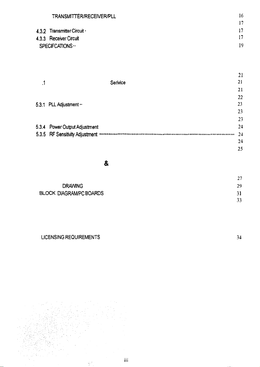
4.3 THE TRANSMITTER/RECEIVER/PLL SECTION
4.3.1 PLL(Phase Lock Loop)
4.3.2
T~nsmi~erCircu~.
4.3.3
Rece~erCir&
4.4 SpEfJFCATlONS..
.......................................................................................................... I()
................................................................................................
.....................................................................................................
.........................................................................................................
.....................................................................
SECTION 5 MAINTENANCE AND ALIGNMENTS
l(j
17
17
17
5.1 GENERAL
5.1 .I Product Support and Customer
5.2 PREVENTIVE MAINTENANCE
5.3 ALIGNMENTS AND SERVICE
5.3.1
5.3.2 Frequency Adjustment
5.3.3 Modulation Adjustment
5.3.4
5.3.5
5.3.6 Weather Alert Frequency Adjustment (RECEIVER)
5.4 TROUBLESHOOTING GUIDE
........................................................................................................................
Se&ice
........................................................................
..........................................................................................
.............................................................................................
PLLAdjusment.. .......................................................................................................
.................................................................................................
................................................................................................
PowerOutputAdjustment .............................................................................................
RFSensi~~tyAdjustmefi
..........................................................................................
......................................................
.......................................................................................
SECTION 6 PARTS LIST & DRAWINGS
6.1 PARTS LOCATION LIST
6.2 ASSEMBLY DRAWlNG
6.3 BLOCK DlAG&5J,&pC BOARDS ......................................................................................
6.4 INTERNAL WIRING DIAGRAM
................................................................................................... 27
......................................................................................................
..........................................................................................
SECTION 7 APPENDIX
2,
21
21
22
23
2.3
23
24
24
24
25
21)
3 1
33
7.1
VHF MARINE CHANNEL USAGE GUIDE AND
LICENSING
REQUIREMENTS
. . . . . . . . . . . . . . . . . . . . . . . . . . . . . . . . . . . . . . . . . . . . . . . . . . . . . . . . . . . . . . . . . . . . . . . . . . . . . . . . . . . . . . . . . . .
34
Page 8
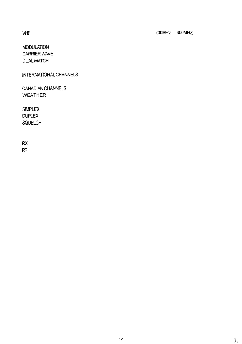
GLOSSARY OF TERMS
VHF
.........................................................
.........................................................
FM
MODU~TlON .............................................
CARRIERWAVE ..........................................
DUAL WATCH .............................................
U.S.A.CHANNELS
INTERNATIONAL CHANNELS ........................
CANAj-JAN CHANNELS .................................
WEATHER
SIMpLU( ...................................................
DUpLu(
SQUELCH
LCD
TX
Rx
RF
CPU
PLL
vco
...................................................
...................................................
.........................................................
............................................................
.........................................................
............................................................
.........................................................
......................................................
......................................................
PTT SWITCH
.......................................
CHANNELS............................
.............................................
Very High Frequency (30MHz to 300MHz).
Frequency Modulation.
To vary a carrier wave.
A radio frequency on which intelligence is superimposed.
Monitors channel 16 while working on another channel.
Channel designations as defined by the FCC.
Channel designations as defined by the international
Telecommunication Union.
Channel designation as defined by the IC.
Channels for routine and emergency weather information
broadcast by NOAA.
Transmit and receive on the same frequency.
Transmit and receive on different frequencies.
To suppress totally.
Liquid crystal display.
Transmit.
Receive.
Radio Frequency.
Control Processor Unit.
Phase Lock Loop (A type of Frequency Synthesizer).
Voltage Controlled Oscillator.
Microphone push-to-talk swith.
iV
Page 9

SECTION
I
GENERAL DESCRIPTION
1 .I INTRODUCTION
Congratulations on your purchase of Apelco’sVHF5200 marine radiotelephone.
The VHF5200 is a CPU-controlled, digitally synthesized, compact transceiver which provides
reliable simplex and duplex (two-frequency) communications between ships and from ships at
sea to public or private shore stations. The VHF5200 provides two-way communications on
the International and US channels, reception on 10 separate weather channels, and two-way
communications on the International calling and safety channel (16).
This manual describes the physical and functional characteristics of the radiotelephone.
1.2 EQUIPMENT FEATURES
The VHF5200 is designed and manufactured to provide ease of operation with excellent reliability. The important built-in features of the equipment are listed below:
.
Waterproofto U.S.C.G. standard CFR-46.
.
All solid-state circuitry for low current drain and maximum reliability.
.
Series diode protection on input power circuits to prevent reverse polarity damage.
.
High-performance receiver section with optimum selectivity.
.
53 channel transmit and 93 channel receive capability within the assigned VHF-FM maritime
band. All US and International channels are included.
.
Exclusive circuit that automatically selects 16 PLUS (priority) channel when the radio is
turned on.
.
Exclusive weather alert feature (when in monitor mode).
.
Selected channel number indicated on the LCD digital display.
.
Key entries for “Quick” 16 PLUS, and 10 weather channels WXO through WX9.
.
All-Scan and Memory Scan features.
1
Page 10
SECTION 2
INSTALLATION
2.1 UNPACKING AND INSPECTION
Use care when unpacking the unit from the shipping carton to prevent damage to the contents,
It is also good practice to save the carton and the interior packing material. The original packing material should be used in the unlikely event it is/necessary to return the unit to the factory.
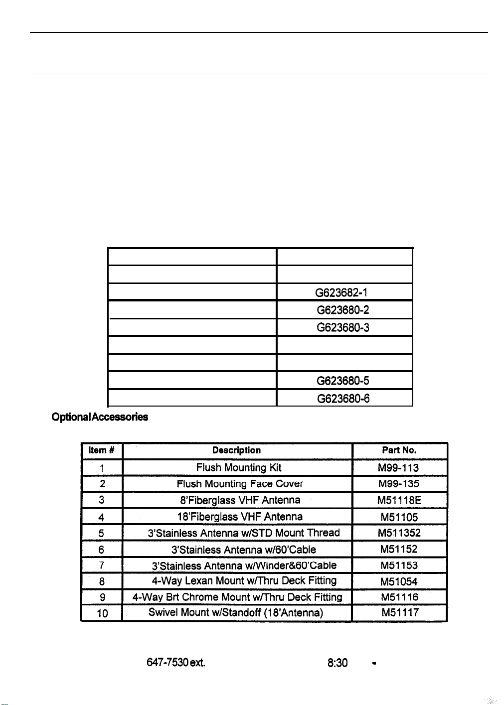
2.2 EQUIPMENT SUPPLIED
The following is a list of materials supplied with the VHF5200:
22.1
OptionalAccessories
Description
Radiotelephone
Instruction Manual
Microphone Bracket w/hardware
Power/External Speaker Cable
FCC Instruction
Mounting Yoke
Yoke Knob
Yoke Knob Spacer
Part No.
M56797
G623682-1
G623680-2
G623680-3
FCC Form 506
G623680-4
G623680-5
G623680-6
Table 2.2 Optional Accessories
These optional accessories may be ordered by calling your Apelco dealer or our Customer Service
Department directly at (603) 647-7530ext. 2120 Monday through Friday 8:30 a.m. - 5:00 p.m. E.S.T.
2
Page 11
2.3 PLANNING THE INSTALLATION
When planning the installation for your VHF5200, the following conditions should be considered to insure dependable and trouble-free operation.
.
The mounting location should be easily accessible to allow operation of the front panel.
l
There should be adequate ventilation for the control unit.
l
A sufficient space should be secured behind the transceiver to allow for proper cable
connections to the rear panel connectors.
l
The transceiver should be located as
l
The selected location should be as far apart as is possible from any devices that may cause
nearto
the power source as possible.
interference such as motors, generators, and other on board electronics.
l
Generally speaking, the transceiver should be protected from prolonged direct exposure to
rain and salt spray.
as much
.
Use adequate sized wire for all DC power connections and make sure to solder all in-line
as
possible.
It is always a good practice to protect your valuable electronic equipment
connectors or splices.
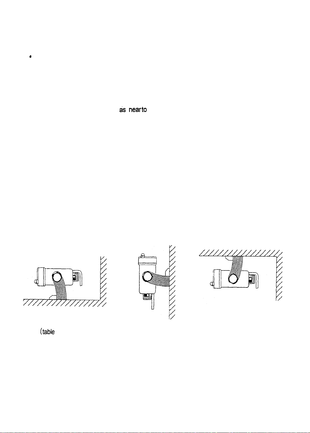
2.3.1 Typical Mounting Methods
The VHF5200 can be conveniently mounted on a chart table, bulkhead, overhead, or any other
desired location. (Refer to Figure 2-1 for typical mounting methods)
(table
top mount)
(bulkhead mount)
(overhead mount)
Fig. 2-1 TYPICAL MOUNTING METHODS
3
Page 12
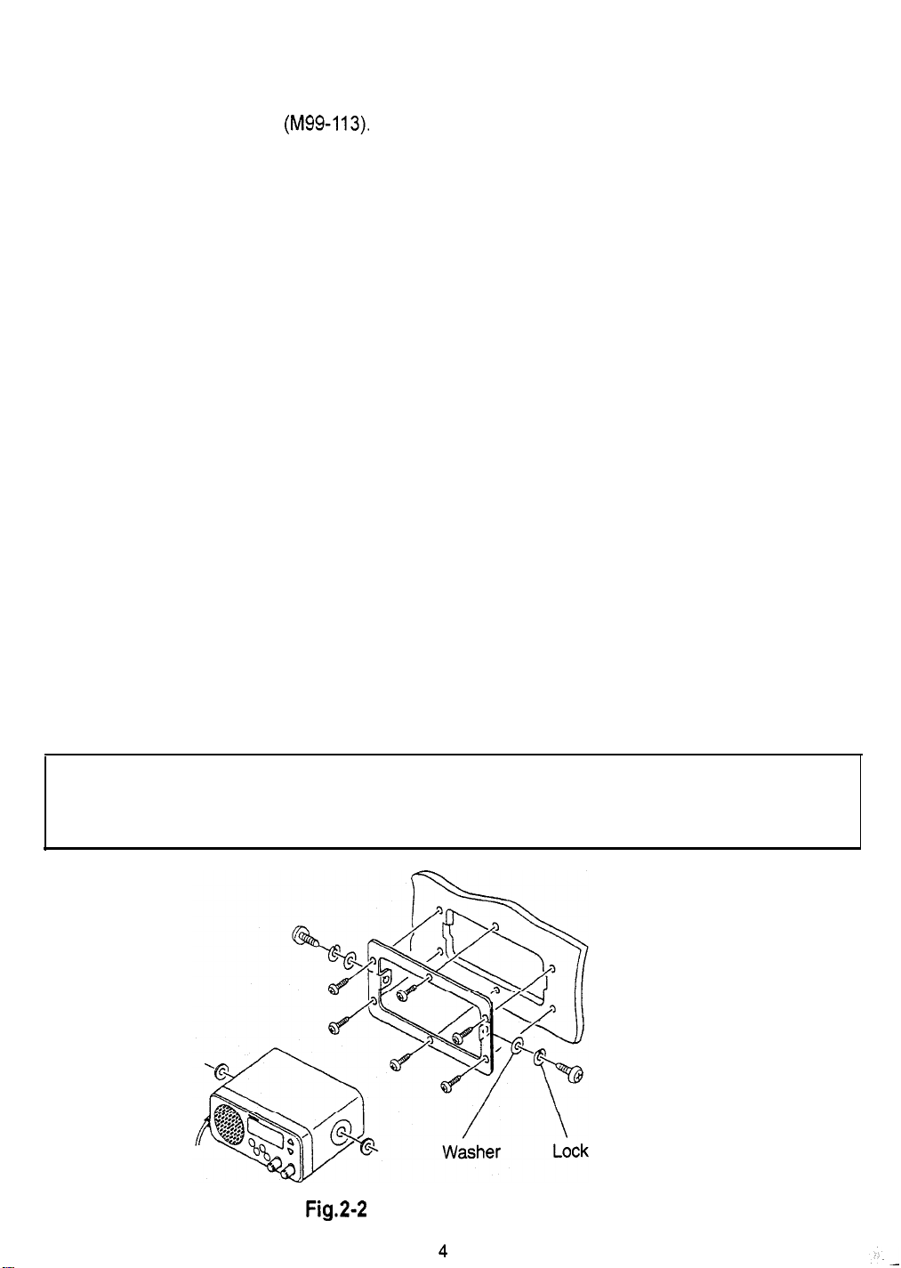
2.3.2 Flush Mounting
In addition to the Typical Mounting Methods, the VHF5200 may also be flush mounted using the
optional Flush Mount kit (M99-113).
These kits are available from your Apelco dealer or our Customer Service Department.
1) Select the location for the VHF. A clear, flat area, of sufficient height having at least 6” of clear
depth behind the panel is required.
2) Unpack the Flush Mount kit and confirm that all hardware is present.
3) Place the ring at the desired location on the panel. Using the inside of the trim ring, trace
a cutout guide. Remove the trim ring.
4) Drill a pilot hole inside of the cutout guide area.
5) Using an appropriate saw, cut along the outside of the cutout line.
6) Remove the yoke knobs and the bracket from the VHF cabinet. Check that the VHF will
fit into the cutout area.
7) Install the power and antenna cables in the console.
8) Insert the trim ring in the console cutout and secure in place with the countersunk flat
head screws. A suitable sealant may be used between the trim ring and console to
prevent moisture entry. Position the radio in the trim ring and secure in place with the two
hex-head bolts and washers supplied.
9) Connect the power/external speaker and antenna cables.
CAUTION
Make sure there are no hidden electrical wires or other items behind the desired location
before proceeding.Check that free access for mounting and cabling is available.
Fig.2-2 FLUSH MOUNTING
4
Washer
Page 13
i i
ig
i
igi
F-1
1
i i
i i
i
+
:
b+!ff!f
TgY
!
/
I
:-
i
-.---
--
J
t
J-
.---
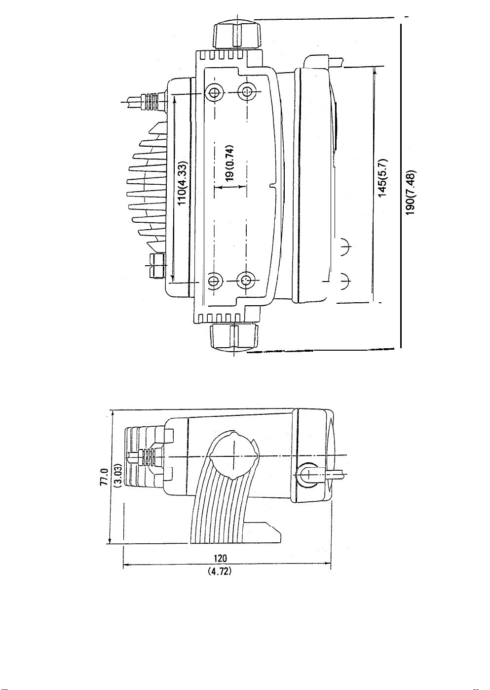
Fig. 2-3 OUTLINE AND MOUNTING DIMENSIONS
All dimensions are shown in (inches) and millimeters
5
Page 14

2.4 ELECTRICAL CONNECTIONS
6
ANTENNA JACK
Fig. 2-4 REAR VIEW
CAUTION
DO NOT INSTALL THIS RADIO ON VESSELS WITH POSITIVE GROUND BATTERY
/
2.4.1 DC PowerConnections
SYSTEMS.
The power cable comes with external speaker attachments. The power/external speaker
cable provided
radio. The RED (+) wire with an in-line fuse (10 amps) and the BLACK (-) wire of the 4 pin
connector cable are used for connecting the VHF5200 to the ship’s 12 VDC power system.
(Refer to Fig. 2-4)
is&
fee3ong and plugs into the 4 pin connector cable at the rear panel of the
POWER/EXTERNAL: SPEAKER CABLE
RED
POWER/EXTERNAL
SPEAKER CABLE
,-(-DC INPUT+)
BLACK
(DC INPUT-)
YELLOW
(SPEAKER+)
*GREEN
CON
'Nl3CTOR
Fig. 2-5 POWER/EXTERNAL SPEAKER CABLE AND 4 PIN CONNECTOR CABLE
CABLE
(SPEAKER-)
Page 15
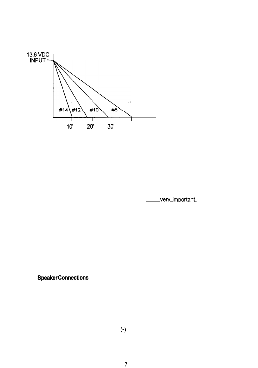
In most cases, the length of the supplied cable should be adequate to reach the DC power
source. If additional wire length is required, the cable can be extended by adding more cable
as necessary. However, for power cable runs longer than 15 feet, larger wire diameter size
should be used to prevent line loss. Fig 2-5 provides recommended wire sizes to use for
various cable run distances.
‘Kb~?~
VOLTAGE
AWG WIRE SIZE
IO’
20’
30’
40
Fig. 2-6 POWER CABLE LENGTH
Your VHF radio should be connected to the nearest primary source of ship’s DC power. A
typical source may be a circuit breaker on the power panel or a fuse block located near the
unit. When connecting to either of these sources, the circuit breaker or other in-line fuse
should be rated at 10 amps.
It is recommended that terminal lugs be used to connect the power cable to the DC supply and
that the lugs should be both
adequate current draw to the equipment. Intermittent operation may result if an inadequate
connection is made to the power source. The connection terminals should be clean and with
no sign of corrosion.
The RED (+) wire is connected to the positive terminal of the power source or battery. The
BLACK (-) wire is connected to the negative (ground) of the power source or battery. Should
the power polarity be inadvertantly reversed, the 10 amp. in-line fuse located in the RED (+)
conductor will open. Check the input power leads for correct polarity with a VOM, reconnect
the leads observing correct polarity, and replace the fuse. Be sure to use the same rate and
type of fuse.
2.4.2 External SpeakerConnections
The YELLOW (+) wire and GREEN (-) wire are used for connecting the VHF5200 to an external speaker. (Refer to Fig. 2-4)
Three 3 watts of audio output power is provided for an external 4 ohm speaker. A suitable
speaker can be purchased from your local marine dealer.
Connect the YELLOW (+) wire and GREEN
marked on the speaker. When connected, the external speaker will function simultaneously
with the internal speaker.
crimped and soldered.
(-)
wire to the speaker observing polarity as it is
This is verv imoortant in order to insure
7
Page 16

2.4.3 AntennaConnections
The coaxial cable from your VHF antenna is intended to be connected to the antenna jack on
the rear chassis using a PL259 VHF-type connector. The antenna cable may be cut to desired
length. If a longer cable length is required, RG-58 50-ohm coaxial or equivalent cable may be
used for antenna runs up to a maximum of 50 feet. If the distance required is even greater,
then we recommend using low loss RG-213 or equivalent cable for the entire run in order to
avoid excessive losses in power output.
If the antenna connector is likely to be continuously exposed to the marine environment, pro-
tective coating of silicon grease (similar to Dow Corning DC-4) can always be applied to the
connector before mating it to the radio to help prevent corrosion. Any other extension or
adapters in the cable run should also be protected by silicon grease and then wrapped with a
weather-proofing tape.
2.4.4 Antenna Mounting Suggestions
The best radio in the world is useless without a good antenna location. Mounting the VHF
antenna properly is very important because how it is mounted will directly affect the performance of your VHF radio. A standard VHF antenna which is designed for use aboard water
craft should be used.
There are several factors to consider so as to maximize the effective communication range of
the radio.
l
SinceVHF transmissions are essentially Line-of Sight, mount the antenna at the highest possible
location on the vessel. The location should also be free of obstructions in order to obtain
maximum range.
l
Use an antenna with the highest possible gain characteristics.
9
If you must extend the length of the coaxial cable between the antenna and the radio, use a cable
designed for the least amount of power loss over the entire cable length.
l
Keep the coaxial cable between the radio and antenna as short as possible.
214.5
Grounding
While special grounding is not generally required for VHF radiotelephone installations, it is a
good marine practice to properly ground all electronic equipment to the ship’s ground system.
The VHF5200 can be connected to ground by attaching a wire to the screw indicated in the
drawing below and then to the nearest ship’s ground connection point. The recommended
wire to be used for grounding is #I 0 AWG.
ANTENNA JACK
FCiWER/EXlERNAL SPEAKER CABLE
Fig. 2-7 TYPICAL GROUNDING METHODS
8
Page 17

SECTION 3
OPERATIONS
3.1 INTRODUCTION
Your VHF5200 has the capability to transmit on 53 and receive on 93 Marine VHF radiotelephone channels. There are channels that are FCC approved but may only be used by authorized stations for specific purposes, depending on the type of vessel (commercial or noncommercial). Refer to Table 3-l on pages 16 and 17. These tables list all of the marine VHF
channels available in your VHF5200 for International and U.S. radiotelephone use. Full familiarization with this table is essential when selecting your channels. The International frequencies
were agreed upon by the attending countries at the 1968 International Telecommunication
Union meeting in Geneva and are in active use around the world. The U.S. channels are those
channels authorized for use in the U.S.A. by the FCC.
3.2 CONTROLS AND LCD DISPLAY
Refer to Fig. 3-l for familiarization with the controls and mode display.
3.2.1 Controls
@
VOLUME Control (On/Off)
Turns the radio On and Off and controls the Volume of the audio output to the speaker.
IAl [VI
The Up and Down keys
Keys
are
used to move the channel numbers up or down. The channel
number can be increased or decreased by one with each key press, or will continue to
increase or decrease the number as long
SQUELCH control
Provides an adjustable input signal threshold to eliminate random RF background noise
during “no signal” conditions. This control sets the signal-to-noise ratio at which a signal
will become audible.
as
the key is held.
I
[I6
PLUS] Key
Used to Select channel 16 immediately. This channel has been preset to channel 16 at the
factory prior to shipment.
PLUS channel. The 16 PLUS key on the microphone has the same functions as the 16
PLUS key on the radio.
jWX/INT]
When pressed once, puts the radio into the weather channel receiving mode. A “WX” will
be displayed on the LCD along with the weather channel number (O-9).When in this mode,
the transmitter is always disabled.
To select International channels, press and hold the
hear “beep” and “INT” will appear on the display. This causes the synthesizer to program
International channel frequencies. When pressed and held again for two seconds, you will
again hear a “beep” and the synthesizer programs US frequencies. (“INT” indication
disappears)
[MON/1/25] Key
When pressed once, the radio enters the MONITOR mode and “MONITOR” is displayed on
the LCD. In this mode, the radio will scan (monitor) 16 PLUS (priority) channel, a selected
working channel, and a weather channel for the weather alert tone.
When pressed and held for two seconds, this key changes the transmitter output power
from 1 Watt
Key
(“IW”
will be displayed) to 25 Watts
Refer to section 3.3.2 for instructions on how to change the 16
WXIINT
(“IW”
9
key for two seconds. You will
disappears) and vice-versa.
Page 18

@
[SCAN] Key
-With no channels entered in memory:
When pressed once, “SCAN” will begin to flash on the LCD and Ail-Scan will be initiated in three
seconds. To stop scanning, press the “SCAN” key again.
-With one or more channels entered in memory:
When pressed once, “SCAN” and “MEMORY” will begin to flash on the LCD and Memory Scan
will be initiated in three seconds. To stop the unit from scanning, press the “SCAN” key again.
-With one or more channels entered in memory:
When pressed once, “SCAN” and “MEMORY” will begin to flash on the LCD. If pressed again
within three seconds, “MEMORY” will disappear and “SCAN” will continue flashing indicat
ing All-Scan is now the selected mode and will be initiated in three seconds.
More detailed operational information is available in Section 3.3.4 Scan Modes.
When the “SCAN” key is pressed and held for two seconds,
LCD and the channel that is selected when the key is pressed will be stored in memory. A
channel may be removed from memory by selecting the channel to be removed and press
ing and holding the “SCAN” key again for two seconds.
LCD. Weather channels can not be placed into memory.
@
PTT (Push-To-Talk) Switch
When pressed, puts the radio into the transmit mode and “TX” will be displayed on the LCD.
All of the above keys except
PlTwill
produce an audible
16PLUS ---@
“beep”when
“MEMORY” will appear on the
“MEMORY” will disappear from the
pressed.
@--
Channel
,-a
Fig. 3-1 LAYOUT OF CONTROLS AND CONNECTORS
10
Page 19

3.2.2 LCD Display
A number of characters appear on the LCD display in different locations. The following list
describes the characters as well as when and where they will appear.
/
I
I
1 WATT SCAN
0
@
wx ALERT
I
0
MONITOR
1
TX INT MEVORY
\
\
w
Fig. 3-2 LCD DISPLAY
0
SCAN: Will flash by itself when All-Scan mode is to be initiated or will
“MEMORY’ when Memory Scan mode
@
1 WATT (High/Low Power): Will be displayed when the transmitter circuits are providing
Watt of power to the antenna. When the transmitter is supplying 25 Watts to the antenna,
the “1 WATT” indication will be extinguished.
@
ALERT (Weather Alert): Will blink when a Weather Alert Tone has been detected.
@
WX (Weather): Will be displayed when the channel selected to be monitored is a weather channel.
@
MONITOR: Will be displayed when the MON/INT key is pressed. This indicates the radio
is in the MONITOR mode.
@
INT (International/USA): Will be displayed when International channels are programmed for use.
“INT’ is not displayed when US channels are programmed for use.
1
is
to be initiated.
flash
in unison with
I
0
TX (Transmit): Will be displayed on the LCD when the Push-To-Talk
indicating the transmitter circuits are providing a signal to the antenna.
@
MEMORY: Will be displayed when the SCAN key is pressed and held for two seconds, or
when the radio is programmed to the MEMORY SCAN mode.
@
LCD Segments: Will display channel number in use.
3.3 OPERATING PROCEDURES
Specific operating procedures for the VHF5200 are presented in this section, General information regarding corrrect marine channel usage may be found in the Appendix section.
the Controls section 3.2.1 beginning on page 10 for a thorough description of all VHF5200
functions.
11
(PTT)
switch is depressed
Refer to
Page 20

3.3.1 Turning the Power On
1) Rotate the ON/OFF/VOLUME control clockwise to turn the radio on.
When the Power is on , the synthesizer automatically programs for USA channel frequencies
and selects the calling channel 16. (Refer to16 PLUS operation to change this channel.)
Setting the Volume
1) Rotate the SQUELCH control fully counterclockwise. Background noise will be heard.
2)
Rotate the VOLUME control for the desired volume level.
SettingtheSquelch
NOTE
1) Rotate the SQUELCH control slowly
SeUing the Power Output
1) Simply press the “MON/1/25” key for two seconds to toggle between 1 Watt output and 25
Watt output. When “1 WATT’ is displayed. the output power is 1 Watt. If “1
extinguished, 26 watts is being output. The choice of power output is dependent upon the
distance of transmission and transmitting conditions. In certain US harbors and on certain
channels, the FCC requires the power to be limited to 1 Watt. On these “required” than
nels, the radio automatically selects the 1 Watt power output when the channel is selected.
Channels 13 and 67 are restricted to 1 Watt operation but may be
To obtain 25 Watt output on these channels, while in transmit mode (pressing the
press and hold the
25 Watts. When the key is released, the radio reverts back to 1 Watt as indicated on the LCD.
SelectingtheChanneI
1) To select the appropriate channel, press the [A] or [I] channel select keys.
select your ‘working” channel.
To Transmit
1) Select the desired mode (INT or USA) by pressing and holding the
When
“INT’
Then press the Push-To-Talk switch and speak into the microphone using a clear normal voice.
2) When the power is initially turned on, simply press the Push-To-Talk switch, the radio will be
ready for transmission on CH 16 or a user selected priority channel (16 PLUS).
MON/lMS
is displayed, International mode is selected. When extinguised. USA mode is active.
key. As long as the
dockwise
NOTE
until the background noise ceases.
WATT”
MON/1/25
ovemdden
key is held, power output will be
WXIINT
in emergencies.
PlT
switch),
Refer to Table 3-l to
key
fortwo
is
seconds.
The VHF5200 is designed to meet the new FCC Rules Part 80.203. which states, if the Push-
To-Talk switch is pressed continuously for over five minutes, transmission is forcibly inhibited.
If this occurs, audible beeps will sound and “TO” (time out) blinks on the LCD until the Push-
To-Talk switch is released. After releasing the Push-To-Talk switch, the radio is ready for
reception.
NOTE
Initial communication contacts are usually made over channel 16 as all
ships and shore stations monitor this channel. Then a shii to a working
channel will be necessary.
To Select a Weather Channel
1) Simply press the
weather channel from 0 to 9 When this mode is selected, the transmitter is always inhib
ited.
2)
If a weather alert signal is received on your selected WX channel (when in the Monitor Mode)
therelsaflv
3.3.2 The 16 PLUS (priority) Channel
The 16 PLUS channel has been preset to channel 16 prior to shipment from the factory, but the
16 PLUS channel can be changed freely, with the exception of all weather channels.
1)
Press the Up [A] or Down
16 PLUS key for three seconds. An audible beep tone will confirm that the selected channel
is stored In memory as the 16 PLUS channel.
WX/INT
e-second audible alarm generated. To cancel the audible alarm, simply press any key.
key, then use the Up [A] or Down
[r]
key to select the desired channel. Then press and hold the
[r]
key to select the desired
Page 21

2) To reselect channel 16 as the 16 PLUS channel. repeat step 1 for channel 16.
3.3.3 Channel Memory
The VHF5200 has the capability of memorizing all U.S. or International channels, The channels
memorized will be scanned in the Memory Scan mode.
1) Channel Memory: To put a channel into memory, simply select the channel to be stored with the Up
or Down arrows. Push and hold the “SCAN” key for approximately two seconds until a
“beep” is heard and “MEMORY” is displayed on the LCD. This procedure can be repeated
for all U.S. or International channels.
2) Memory Clear: To clear a channel from memory, select the channel to be cleared with the Up or
Down arrows. Press and hold the “SCAN” key for approximately two seconds until a “beep”
is heard and “MEMORY’ disappears from the LCD.
3.3.4 Scan Modes
The VHF5200 is equipped with two types of scan options, All-Scan and Memory Scan. How
these options are accessed is dependent upon whether there are any channels stored in
memory.
1) All-Scan mode
If no channels are stored in memory, when the SCAN key is pressed once, “SCAN” will
begin to flash on the LCD. In three seconds, if no other keys are pressed, the radio will begin
scanning all channels (except weather channels) as long as no signal is received. If a signal
is received, the scan will stop and monitor the receiving channel. If the signal is lost for five
seconds, the radio will resume scanning. If the scan has stopped on a received signal, you
may resume scanning by pressing the SCAN key. To cancel the scan mode, press the
SCAN key once while the radio is scanning.
2) Memory Scan mode
If one or more channels are stored in memory, when the SCAN key is pressed, “SCAN” and
“MEMORY” will begin to flash simultaneously on the LCD. If no other key is pressed, the
radio will begin scanning all channels currently in memory in three secondsAs with All-
Scan, if a signal is received, the scan will stop on the receiving channel until the signal is lost
for five seconds or the SCAN key is pressed. To cancel memory scan, press the SCAN key
while the radio is scanning.
If you have one or more channels in memory and want to initiate Ail-Scan, perform the following:
Press the SCAN key. “SCAN” and “MEMORY’ will flash on the LCD. Press the SCAN key
again within three seconds and “MEMORY’ will disappear from the LCD leaving only “SCAN”
flashing. All-Scan will begin in three seconds if no other key is pressed.
3.3.5 Master Reset
To perform a master reset, press and hold the 16 PLUS key while turning the unit on. This feature
clears all channels from memory and programs the 16 PLUS feature back to channel 16.
3.3.6 Monitor Mode
Before entering the Monitor Mode you must first select the WX channel you wish to monitor for
the weather alert tone. Next, you must also select a working channel to be monitored for traffic.
(Refer to section 3.3 for instructions on channel section) For this example, we will use channel
83 as our working channel and
key and the radio will begin to scan the channel designated for 16 PLUS, 83, and WX2, repetitively.
monitored channels. To cancel the Monitor mode, press the MON/1/25 key again.
___.....__.
Working Channel
lf a
and the selected weather channel every five seconds.
16 PLUS (priority) Channel
If while scanning, a signal is received on the designated 16 PLUS channel, the scanning will stop on 16
PLUS as long as the signal is being received. If the signal ceases for more than five seconds, the
scanning will continue.
Weather Channel
The 16 PLUS channel programmed into the radio is automatically selected as one of the
-..-
. . . .
-.
Signal
iS
received on CH 83, the scan will stop on CH83, but will continue to monitor 16 PLUS
Until a weather alert tone signal is received on WX2, the scan will stop on
WX2
as our weather channel. Now simply press
WX2
briefly, but will not
the MON/1/25
give any audio output. When a weather alert tone (1050 Hz) is received, the monitor will stop and an
audible alarm will sound. When the audio alert ends in five seconds, the emergency weather
broadcast will be heard. To silence the alarm, simply push any key.
13
Page 22

3.3.7 VHF5200 Marine Channels and Their Usage
CAUTION
The transmitter of the VHF5200 is disabled when channel 15 or WXO -
FREQUENCY (MHZ) FUNCTION
CHANNEL
DESIG.
Ol#
M#
03#
04#
OS
06
07
08
09
10
11
12
13"
14
1%
16
17.
18
19
20
21(CG)
WW
23(CG)
24
25
26
27
28
60+
61~
62~
63
64+
TX
156.050 156.050 160.650
156.100
156.150 156.150 160.750
156.2Kl 156.200 160.800
156.250 156.250 160.850
156.300 156.300 156.300
156.350 156.350
1.56.400
156.450 156.450 156.450
156.500 156.500 156.500
156SSO
156.600 156.600 156.600
156.650 156.650 156.650
156.700 156.700 156.700 Pori Operations YeS Yes
156.800 156.800
1.56.8SO
156.900 156.900 161.500
156.950 156.950 161.550
1.57.000 IS7.OOLl
157.oso
157.100 157.100 161.700
157.1so 157.150 161.750
157.200 161.800 161.800
157.250 161.850 161.850
157.300
157.350
157.400 162.000
156.025 156.025 160.62s
156.075 156.075 160.675
156.125 156.125 160.725
156.175 156.175 160.775
156.225 156.225 160.82s
Cl%)
156.100 160.700
156.400 156.400
156.550 156.550
156.750 156.750 l3wironmental
lS6.85il
157.050 161.650
161.900 161.900
161.950 161.950
(ZL)
160.950 GJm’l Yes Yes
156.800
156.850
16X.600
162.000
TYPE OF TRAFFIC
-
-
-
-
Port Operations Yes Yes
Intertip
corn'1
call & ship/ship
Corn’1 &
Corn’1 &
Port
Nav. Ship/Bridge
Em~g/CaUii Yes
State Controlled Yes
Com’l
Corn’1 Yes YeS
Port Operations YeS YeS
Coast Guard
CoastGuard
Coast Guard
Public
Public
Public
Public
Public
-
-
-
Corn’1 Yes Yes
-
WX9
is displayed.
SHIP TO
SHIP
Safety Yes No
Yes
ship/ship
Ship/Ship
Operations
Comesp. No Yes
Corrwp. No YeS
Corresp. No Yes
Gxreap. No YeS
Coaaap. No YeS
YeS
Yes Yes
Yes
YeS Y&S
Ye.5
Yes YeS
Yes YaS
Yes
Yes Yes
SHIP TO
SHORE
No
YES
Y&S
YeS
YES
YeS
Yes
Table 3-1
* 1 Watt only
** 1 Watt initially. User can override to high power (25 watts) via front panel controls.
#
The transmitter is automatically disabled when channels 1,2,3, and 4 for USA are selected and when 15
for USA and International are selected.
+
Assigned by the Canadian Government, proper authorization must be ensured prior to use.
CAUTION
Operation on channels not designated for use by your classification of craft or on International
Channels within the US territorial waters is a violation of F CC Rules and Regulations and may
result in severe
penafties.
14
Page 23

CHANNEL
DESIG.
6.5
66
67”
68
69
7OtI
71
72
73
74
75#
76#
77’
78
79
80
81
82
83
84
85
86
87
88
FREOUENCY (MHZ)
-
TYPEOFTRAFFIC
TX
156.275 156.275 160.875
156.325 156.325 160.925
156.375 156.375 156.375
15 6.425
156.475 156.475 156.475 Non
156.575 156575 156.575 Non
156.625 156.625 156.625 Non
156.675 156.675 156.675
156.725 156.725 156.725
156.875 156.875 156.875
156.925 156.925 161.525 Non
156.975 156.975 161575
157.025 157.025 161.625
157.075 157.075 161.675
157.125 157.125 161.725
157.175 157.175 161.775
157.225 161.825 161.825 Public Cmresp. No Yes
157.275 161.875 161.875 Public
157.325 161.925 161.925 Public Gnesp.
157.375 161.975 161.975 Public Corresp.
157.425 157.425 162.025
(lIEi)
156.425 156.425 Non
156.525 156.525 DSC Yes Yes
156.775 156.775
156.825 156.825
(IN?L)
Port
Operations Yes Yes
Port Operations
Corn’1
Corn’1
Corn’1
Corn’1
Corn’1
Porl
Operations Yes Yes
Port Operations
-
-
Port Operations
Corn’1
Corn’1
Corn’1
Coast Guard
Coast Guard
Coast Guard
Gnesp.
Corn’1
FUNCTION
SHIP TO SHIP TO
SHIP
Yes Yes
Yes
Yes Yes
Yes Yes
Yes Yes
Yes
Yes Yes
Yes
Yes Yes
Yes Yes
Yes Yes
Yes Yes
Yes Yes
Yes Yes
No
No
No
Yes
SHORE
No
No
No
Yes
Yes
Yes
No
Table 3-1 (Continued)
*
1Watt
only
c*
1Watt initially. User can override to high power (25 watts) via front panel controls.
#
The transmitter is disabled when channels 75 and 76 are selected. Channel 70 is now used for DSC calling
only, therefore transmission on this channel is disabled on this radio.
CAUTION
Operation on channels not designated for use by your classification of craft or on International
Channels within US territorial waters is a violation of FCC Rules and Regulations and may result
in severe penalties.
VHF 5200 Weather Channels
CHANNEL FREQUENCY (MHZ) TYPE OF TRAFFIC
WO
WC1
w2
w3
w4
xx5
wX6
WY7
WX8
wx9
163.275
162.550
162.400
162.475
162.4'25
162.450
162.500
162.525
161.650
161.775
NOAA Weather
NOAA Weather Receive Only
NOAA Weather
NOAA Weather
NOAA Weather Receive Only
NOAA Weather
NOAA Weather Receive Only
NOAA Weather Receive Only
Canadian Weather Receive Only
Canadian Weather Receive Only
and Frequencies
FUNCTION-SHIP TO
SHORE
Receive Only
Receive Only
Receive Only
Receive Only
15
Page 24

SECTION 4
TECHNICAL DESCRIPTION
4.1 GENERAL
The VHF5200 can be considered as consisting of two major sections. They are:
l
The Control Circuitry (consisting of the front panel controls, the LCD display, control
CPU).
l The
Transmitter/Receiver/PLL
circuits.
4.2 THE CONTROL SECTION
The heart of the control section is the CPU, IC201, located on the main PCB.
The CPU controls all of the following items:
l
Controls the Squelch circuit by detecting a busy signal from the second IF circuit
l
Generates a beep tone when a key is activated on the keyboard.
l
Mutes the transmitter modulation circuit when receiving.
l
Controls the output power of the transmitter High/Low.
l
Controls the dividing ratio N of the PLL circuit.
l
Switches On/Off the transmitter power.
l
Mutes AF audio.
l
Detects a weather alert signal (when in Monitor Mode).
IC5.
l
Controls the LCD display.
4.3 THE
TRANSMITTERIRECEIVERPLL
SECTION
In reading through the following circuit descriptions, it may be helpful to refer to Figure 4-l Block
Diagram of the TX/RX/PLL circuits.
16
Page 25

4.3.1 PLL (Phase Lock Loop Circuit)
The PLL circuit is the frequency synthesizer in the VHF5200.
The reference frequency of 12.8 MHz is provided by crystal
XTLI
and IC3. IC3 contains the
reference oscillator (12.8 MHz) circuit, the phase comparator, the program counter and the
phase detector. The 12.8 MHz reference signal is divided by 512 in the program counter in IC3
to obtain a 25 KHz reference signal. The dividing ratio is determined by CPU
IC201.
output from oscillator Q4 is amplified by buffer amplifier Q3, and returned to IC3 and is divided
by the dividing ratio N to obtain a 25 KHz signal. N for 1 N in lC3 is determined by CPU
Both of these
25KHz
signals are fed into the phase comparator circuit of IC3.
The phase detected signal, obtained by comparing the phase difference between these two
signals, is applied to LPF between pins 11 and 12 of IC4 to get a DC voltage correlated with the
phase difference.
The DC voltage acts on the VCO to make the two 25 KHz signals the same phase. When this
condition is met, the PLL circuit is locked. If the two signals have a large phase difference, the
PLL is unlocked. In this condition, the unlocked signal is fed to CPU IC201 from lC3 and the
transmitter is compelled to stop.
The VCO output from Q4 is fed to the TX amplifier Q2 and the first RX mixer
Ql9
buffer amplifier Q3.
4.3.2 Transmitter Circuit
A signal from the microphone is fed to a pre-emphasis operations amplifier IC3, and modulates
VCO(Q4) through active LPF IC2.
The VCO output signal from Q4 is sent to the RF power amplifiers ICI, Ql and Q2 through
buffer amplifier Q3. The RF signal from ICI is fed to the antenna through a low pass titter.
The DC voltage correlative to the RF output is detected by 02 and Q9. amplified by Q24 and
fed to ICI .The output voltage from ICI controls the RF power to keep the RF output at a con
stant level.
The VCO
IC201.
through
4.3.3 Receiver Circuit
1) RF Circiut
The signal from the antenna passes through the single tuned band pass filter, and is amplified by RF
amplifier Q17, and is fed into a triple tuned band pass filter. The signal is then mixed by
(first mixer) and produces the first IF signal of 21.6 MHz. This signal is sent to a crystal filter
(21.6 MHz) and first IF amplifier Q20, mixed by IC4 , the second mixer, and becomes an
audio signal after detection.
2) IF Circuit
The output of the first IF amplifer Q20 is fed into IC4. IC4 contains the second mixer, second
local oscillator, 455KHz amplifer, quadrature detector and DC switching amplifer.
A455 KHz ceramic filter is installed between pins 3 and 5 of IC4 to examine the selectivity of
this unit.
The detector output is separated into audio and noise components by an RC filter. The noise
component is fed back to the noise amplifer section of 164. Its output is rectified by a diode
in IC4 and then fed to the switching amplifer in IC4.
3) AF Circuit
The AF signal from IC4 is amplified by IC5 to drive the speaker while the receiver is in the
squelched condition. Muting control of IC5 is carried out by the CPU IC 201.
4) Weather Alert Tone Detecting Circuit
If a weather alert tone is included in the AF signal from IC4 while receiving the weather service
broadcast, IC6 detects it and notifies an alert condition to CPU
Q19
IC201.
17
Page 26

BLOCK DIAGRAM
co
Fig. 4-l VHF 5200 Block Diagram
Page 27

4.4 SPECIFICATIONS .
Transmitter
Channels
Frequency Stability
Frequency Range
Channel Spacing
Power Output
Modulation
Modulation Audio Response
FM Hum & Noise Level
Audio Distortion
Spurious & Harmonic Emssions
53 US/international
IOPPM ( 0.001%)
(-20 “c
156.025 to 157.425MhHz
25 KHz Increments
25 Watts switchable to 1 Watt into 50 Ohms at 13.6 Vdc
Frequency modulated
(rt4.5KHz at
Shall not vary
2500Hz, reference 1000 Hz. Audio frequences 3-20 KHz shall be
attenuated (at 1 KHZ by 60 log f/3
Greter than
Less than 10% at 1 KHz for+3KHz deviation
Attenuated at least
per FCC Rules Parts 2 & 80
to+50c)
IOOOHz)
-4OdB
+I/-3 dB
below audio
43+10
16F3
from true 6 dB pre-emphasis from 300 to
dB.
Above 20KHz by 50dB)
log PO (below rated radiated carrier power)
Antenna Impedance
Transmitter Protection
Receiver
Channels
Frequency Range
Frequency Stability
Usable Sensitibivity
Squelch Sensitivity Threshold
Adjacent Chl Rejection
Spurious Image Rejection
Intermodulation
Rejection
50 Ohms
Shall survive open or short circuit of antenna system without damage
(10 min.test)
93(inciudes 10 weather channels
‘156.25 to 163.275 MHz in 25 KHz increments
+lO
PPM(O.OOl%)
0.3fiV for 12dB
0.2,~V
or better
1 .O,V full squelch
Greater than 70
Greater than 70
Greater than 70
from -20°C to +50%
(SINAD)
dB
dB
dB
19
Page 28

Audio Output
3 Watt or more at 10% or less distortion into 4 Ohm load
Hum & Noise in Audio
Operating Requirements
Input Voltage
Current Required
Transmit
Operating Temperature
Duty Cycle
Humidity
Radio Dimensions
Height
Width
Less than -4OdB
13.6 Vdck15%(11.6 to 156Vdc)
Less than 5.8 amp at 25 Watts
Less than 1.5 amp at 1 Watt
-20°C to +5O”C
Continuous, 80%receive, 20%transmit
(max 1 Omin,
100% at
54 mm (2.2inches)
145 mm (5.7 inches)
@25”C)
50°C
for 8hours
I
Depth
Weight
120
mm
Arwox.
(14.72 inches)
7509
(1.7 lb)
20
Page 29

SECTION 5
MAINTENANCE AND ALIGNMENT
5.1 GENERAL
The purpose of this section is to provide maintenance and servicing instructions for the service
technician. The equipment is designed to provide long periods of trouble-free operation. It is
recognized, however, that environmental and other factors will result in a need for occasional
service.
5.1 .IProduct Support and Customer Service
“We at Apelco, have gone to great lengths to insure that the product you have purchased holds
up to our high quality and performance standards. If, however, you are ever in need of service,
please contact Apelco directly, or an authorized Apelco dealer for assistance. You may contact Apelco directly at the following numbers, to speak to one of our knowledgeable and courteous specialists”.
Customer Service: (603) 647-7530 ext 2120
Phone calls to this deparment should deal primarily with questions regarding Purchasing Parts
and accessories, authorized Apelco dealer locations, basic product information, and brochure/
literature requests.
Product Support: (603) 647-7530 ext. 2444
Phone calls made to this deparment should deal primarily with the operation and technical
aspects of Apelco Marine equipment.
When calling the above numbers, your phone call will be placed in a queue and will be answered in the order in which it was received. The normal operating hours for this system are
from 8:30am-5:OOpm Eastern Standard Time.
5.2 PREVENTIVE MAINTENANCE
The VHF5200 has been constructed to be virtually maintenance free. Your attention to a few
basic points should assure many years of service.
1)
Although the unit is waterproof, always keep the unit as dry as possible.
2)
Clean the exterior of the unit with a tissue or soft non-abrasive cloth.
CAUTION
Do not use solvents or other chemicals for cleaning this equipment
3) Inspect the radio case and antenna for any physical damage.
21
Page 30

5.3 ALIGNMENTS AND SERVICE
This transceiver is completely aligned at the factory and does not require any adjustments at installation.
The test equipment listed below are used for the test setup shown in Fig
part or in total during the following adjustments.
5-I
.This test setup is used either in
TEST EQUIPMENT
1.
DC Power Supply
2. RF Power Meter (40W$Oohn,l50-200 MHz)
3. RF Signal Generator
4.
FM Linear Detector (FMLD) or Deviation Monitor
5. Frequency Counter
6. Digital Voltmeter (DC Voltmeter)
7.
Oscilloscope (any osilioscope accurate for audio signal tracing)
8.
SINAD
Meter
9. Distortion Meter
10. Toggle Switch (for use as a PTT switch)
11. Coaxial Switch for TX/RX antenna switching
(2OV,lOA)set
(5Oohm
Output,l50-200MHz)
at
13.6Vdc
150-200MHz
22
Page 31

L
5.3.1
PLL Adjustment (TRANSMITTER/RECEIVER)
1) Connect the power supply (13.6 V,lO A)to the power line and the PTT switch to the microphone terminal.
2) Connect a digital voltmeter or high impedance tester (positive lead to TPl negative to
ground) and adjust Tl on the RF module as shown in Table 5-l (See Fig 5-2)
Sequence
1
FF
53.2 Frequency Adjustment (TRANSMITTER)
1) Connect the coupler output to a frequency counter, set the radio on
key the transmitter, and read the indication on the frequency counter.
2) Adjust trimmer capacitor CVI on the RF module for the desired frequency(l56800MHz)
&200
Hz on the frequency counter.
5.3.3 Modulation Adjustment (TRANSMITTER)
1) Connect the coupler output to an FM linear detector.
Connect an audio oscillator to the microphone connector and key to
2) Set the audio oscillator output to-20 dBm,300 Hz and adjust RV 3 on the RF module for a
deviation of 4.5 KHz ? 300 Hz.
3) Set the audio oscillator output to 43 dBm,l KHz and read the deviation meter
-23.2
KHz).
Item
TX transmit CH.60 USA
RX receive CH.60
RX
Condition
receive CH.WXO
Table 5-l
Ad/.
point
Tl
-mm
---
CH16(156800MHz),
the transmitter,
Adj. volt.
3.5
zk
check for
check for 3.4+
(k2.8
KHz
0.1 Vdc
1.652 0.3Vdc
0.3Vdc
23
Page 32

5.3.4 Power Output Adjustment (TRANSMITTER)
1) Connect an RF power meterto the antenna connector through the coupler.
adjust
RVI
and RV2 on the main PCB as shown in Table 5-2. (See Fig.
Sequence Condition
1
2
5.3.5 RF Sensitivity Adjustment (RECEIVER)
1)
Connect an RF signal generatorto the antenna connector and a SINAD meter to the external
speakerline.
2)
Set the deviation of the RF signal generator to 1 KHz
3) Set the output level of the RF signal generator and adjust T2-T6 and T301 on the RF
module as shown in Table 5-3,(See Fig.52).
I
Sequence Conditlon
1
13.6VDC H/‘L:L
13.6VDC
CH.BB(157.425MHZ)
SG output:60dBu
H&H
Table 5-2
Ad].
Point
RVl
LOW
RV2
High Power
+/-
3 Hz.
Adj. Point
I
TZ-T6
T301
I
Power
Key to transmit and
5-2)
Target Power
o.gw+/-0.05w
(limit
1.0 w)
24w+/-0.5~
(limit25w)
Target Level
Max.Sensitivity
2
5.3.6 Weather Alert Frequency Adjustment (RECEIVER)
1) Connect an RF signal generatorto the antenna connector
Set the RF signal generator as follows:
. Frequency:
l Output level: 60dBu
2) Select the weather channel
3)
Connect a frequency counter to TP3 on the MAIN PCB and adjust VR4 to obtain 1050 kHz
+/- 5 Hz on the frequency counter. (See Fig. 5-2)
CH.WXO
SG output:-6dBu
I
162.550 MHz with no modulation
WXI
.
I
Table 5-3
Eii6
Over 12 dB SINAD
I
24
Page 33

5.4 TROUBLESHOOTING GUIDE
Table 5-4 provides a general troubleshooting chart for use by a technician to isolate circuitry failures to
specific functional areas within the VHF radio.
1
Miiponents within the radio are generally not field replaceable. Therefore repairs to the
radio typically go down to the PC board level only.
can be found in Section 6.
r
Item Number
I
1
2
3
4
NOTE
A replacement parts iii for the VHF 5200
Symptom Possible Cause
Unit does not turn on
No sound with AF signal
applied to pins 1 and 2 of
IC6 components
No sound with AF signal
applied to volume control b. Defective mute circuitry
Squelch circuit
inoperative
a. Defective power switch
b. IOamp. Fuse in power line open
c. Diode
d. Noise filter
e. Capacitor Cl19 and Cl20 shorted
f. Defective regulator
a. Defective internal speaker
b. Defective
a. Defective volume control
a. Check squelch control
(b.
Dll
open
L15
open
IC7(5v)
IC5
and/or associated
Defective
between pins 7 and 9
IC4and
/or associated circuitry
(IC201)
No receive (Rx) a. Defective regulators
b. Defective
c Check IC4 audio output voltage at pin 9
d.
Defective AF amplifier
e. Defective mute circuitry
f.
5
Low receiver sensitivity
6
Check XLT2 output for 21.145 MHz signal
g. Check 21 .GMHz output of first mixer
h. Check 216MHz output of ceramic filter IF amplifier FILI
i.
Check 21 .GMHz output of first IF amplifier Q20
j. Check 455KHz signal from ceramic filter
k. Failure of VCO circuit
I.
Defective CPU
a. Check antenna and connector for possible
corrosion or bad connection
b.
Failure of the output from
IC4
c. Check the output level of
QlB(RX
B+)
(IC201)
IC7(5V)
Q21
IC201
(Q4,Q3,
QIQ
and/or PLL IC3)
Q17,
QIQ,
VCO per
para.
QZO,
FlL2
and/or
5.3.1
Table 54 TROUBLESHOOTING CHART
25
Page 34

Item Number Symptom
Possible Cause
8
9
10
CPU inoperative
7
Display malfunction
No transmit (TX)
Low RF power output a. Check RF power output from ICl . If it checks
a. Turn off the power once, and try again
b. Check CPU clock frequencies (pins 22 and 23, and
pins 26 and 27 of IC201)
c. If clock frequency is not present, check for
+SVDC
line
a. Check the interconnection to the LCD display
b. Inoperative CPU
a. Defective
b. Defective regulators IC7(5V)
c. Defective Ql2(TX +B)
d. Check power transmit circuit @I
e. Failure
f. Check PLL control voltage for 3.5 VDC at TPI on
channel 60.
g. Failure of talk detection circuit
good, check the triple Pi type network components
(C26,Ll-3,etc.) and antenna switching diode
(D4). If not good then check the voltage level
outputs of the drive amplifiers Qland Q2 as well as
the associated circuitry
b.
Check
IC4
PlT
switch
,Q2,and/or
oflVC0
circuit (Q4 and /or Q3) or PLL IC3
(IC201)
power control circuit (Q24,Q9,QlO) and
ICI)
11
12
Poor or no modulation
PLL output frequency or level
incorrect
Table 54 (Continued)
a.
Check,VCO
PLL phase detector output at pin 12 of PLL
associated circuitry
b. Check 12.8 MHz crystal
a. Check frequency of 12.8 MHz
b. Check the frequency input at pin 14 of IC3 and
verify
output frequency at pin 14 of PLL IC3
IC3
(XLTI)
crystal(XLT1)
the transmit frequency
and
26
Page 35

PARTS LIST AND DRAWINGS
6.1 PARTS LOCATION LIST
SECTION 6
MAIN PCB ASSEMBLY SECTION
CKT, SYMBOL DESCRIPTION
I
Main PCB Assembly
D1,4
D2
D3
D5
D8
D7
D8
D9
DIO
Dll
FL101
F901 ,F907
F905
F906
ICl
IC2
IC3
Ic4
IC5
IC6
IC7
Ant SW, Ml 308
RF Power Det,
----~~~~~~~~~~~~---
RF SW, lSVl28
ModNariICap, ISV214
VCOAfarilCap,
SW, ISS226
SW, DAN202
Isolator, DAN202
Isolator, FMBG24
Xtal, 32.768 Khz
Xtal, MF21.6-RB
Xtal, 21
Xtal, 12.8 Mhz G263479-55
TX Power Module, M5771 OA (or S-AV6) 1032698-85
OPAmp, 2902M
PLL IC, LC7153M
FN IC, TA31136FN
AF Power Amp, LA4485 G263720-10
Tone Detector,
+5V Regulator, 78M05
.I45
IS%45
Khz
BAI
KVI
832C
604
PART NO.
G623681-1
I
Ql
cl2
cl3
CM
Q5
Q6,8,11,15,23
Q7
Q9
QIO
TX Driver, 2SC3357
TX Pre-Driver, 2SC4226
Buff Amp, 2SC4226
VCO, 2SK508
DC Fil, 2SC4116
SW, DTCI 14EK
SW,
2SA81 IA
DC Control, 2SB1185
DC Control, 2SC4116
27
Page 36

MAIN PCB ASSEMBLY SECTION (CON’T)
CKT, SYMBOL DESCRIPTION PART NO.
Q12,13
Q14
Q16,21
Q17
Q18,22
Q19
Q20
Q301
CKT, SYMBOL DESCRIPTION
H200
IC201
IC202
IC203
SW, 2SA1298
SW, DTA124EK
AF SW, DTC343
RF Amp, 2SC4226
AF Amp,
First Mixer, 2SK508
First IF Amp, 2SC3123
High Pass Filter, 2SC4116
CPU PCB Assembly
LCD, 211
CPU, M34520M6
EEPROM, 93LC46X
Reset, RH5VA45AA
2SC4116
CPU PCB ASSEMBLY SECTION
PART NO.
G623682-2
PL-201
Q201
Q202
CKT, SYMBOL
Pilot Lamp, 93 (14V) G263720-24
Sw,2sal298
SW, DTCl24EKT
VOLUME/SQUELCH PCB ASSEMBLY
DESCRIPTION
Volume/Squelch PCB Assembly
28
PART NO.
G623681-3
Page 37

Main PCB-Bottom view
Main PCB-Top view
CPU PCB-Top view
Bottom view
CPU PCB-Bottom view
Fig. 6-3 VHF 5200 PCB LAYOUT
VOUSQ PCB
Top view
32
Page 38

1
INTERNAL WIRING DIAGRAM
POWER CORD
03
L1
MIC UNIT
P500
sl
TOA0
ii
E:
s
\
MAIN
PC6
CNIOI
TO CN202
Fig. 6-4 INTERNAL WIRING DIAGRAM
33
Page 39

SECTION 7
APPENDIX
7.1 VHF MARINE CHANNEL USAGE GUIDE AND LICENSING REQUIREMENTS
Most of the information found in this section is reprinted in whole or in part from FCC information Bulletin No. 2 REVISED EDITION February 1991 and FCC Fact Sheet PR-5000 March 1990.
REMEMBER:
l
Maintain a radio watch on Channel 16. Channel 16 is used for distress and safety purposes
&
l
Use VHF Channel 70 only for Digital Selective Calling (DSC). It may be used for general-purpose calling using DSC. Your cooperation in not using Channel 70 for general intership com-
munications is necessary to prevent interference.
l
Your VHF transceiver has a high-low power switch. Use low power whenever feasible.
Unnecessary high-power operations can interfere with other important communications.
l
Always use your radio call sign at the beginning and end of each transmission.
l
Be sure only qualified persons operate your radio. You are responsible for control of your radio.
Know the rules.
l
Limit calls to other vessels to 30 seconds. If you receive no reply, wait 2 minutes; then try
again. Keep communications brief and avoid chit-chat.
l
Never transmit false distress messages, and never use profanity on the air.
OTHER REMINDERS:
l
Do not install or operate your radio until it is licensed. You can obtain a station license and call
sign by completing FCC Form 506 and mailing it with the required fee to the FCC, Marine Ship
Service, PO. Box 358275, Pittsburgh, PA 15251-5275. Form 506-A provides you with immediate operating authority, valid for 90 days after you mail your license application.
You need a radio operator license to operate a VHF Marine Radio only if you plan to dock in a foreign
port or leave a foreign port to dock in a U.S. port.
l
Your radio license is not transferable. If you sell your boat, request the FCC to cancel your sta-
tion license.
34
Page 40

If you replace your radio, you do not need to change your license unless the new radio operates on
another frequency band. If you install equipment to operate on another frequency band, apply for
modification of your license.
l
If you carry more than six passengers for hire, your vessel must be certified as a passenger-
carrying vessel by the FCC and the Coast Guard.
Licensing Requirements for Hand Held Portable VHF Marine Transceivers
10 Watts Power or Less
All transceivers, hand helds included, operated in the Maritime Radio Services are required to be
operated under an appropriate maritime station license.
Operation of hand held VHF Marine trans-
ceivers without proper station license can lead to fines and/or administrative sanctions issued against
its user and/or owner.
VHF Marine hand held transceivers can be operated and licensed as follows:
a)
Associated Ship Unit: A hand held VHF Marine transceiver can be operated under an exist-
ing valid ship station license under the following conditions only:
i)
Except for safety purposes, the hand held transceivers must be used only to communicate with the ship station with which it is associated. Such associated ship units MAY
NOT be operated from shore.
ii)
The transmitting power is limited to ONE WATT only.
iii)
The hand held transceiver must be identified by the call sign of the ship station along with
its associated unit designator.
b)
Portable Ship Station: The Commission may grant a station license permitting operation of a
portable ship station aboard different vessels of the United States. Each application (FCC
Form 506-Application for a Ship Radio Station License) for a portable ship station license
must include a showing that:
i)
The station will be operated aboard a vessel.
ii)
A station license for portable equipment is necessary to eliminate separate applications
to operate a ship station aboard different vessels.
c)
Marine Utility Station: A utility station in the maritime mobile service consists of one or more
hand held transceiver units licensed under a single authorization. Each unit is capable of
operating while being hand carried by an individual. There are two types of stations autho-
rized:
i)
Marine Utility Coast- when transmitters are located on land; may communicate directly to
vessels only.
ii)
Marine Utility Coast/Ship- transmitters from land may communicate with vessels or when
aboard a vessel, may communicate with other vessels or coast stations.
NOTE: A Marine Utility Ship license will not be authorized.
35
Page 41

The station operates under the rules applicable to a private coast station when the unit (s) are on land
and under the rules applicable to a ship station when the unit (s) are aboard a vessel. FCC Form 503,
application for Land Radio Station License is used when applying for a marine utility License.
USAGE GUIDE
.*
.
m
Emwgmcy
NSViptii
PZJ
Cslling
u. s. coast Guwd
state control
Environmental
WMhW
36
Page 42

:::y:::::
.*I.-.*.*.
ELI
Emergency
Channel 16
If:
l
Your ship is
l
Someone has been lost overboard
l
There exists grave and imminent danger
Use this distress procedure:
l
Select Channel 16
l
Say “Mayday, Mayday, Mayday.”
l
Give call sign and boat name
l
Give location of boat
l
Describe emergency
l
If no answer, repeat; then try and other
channel
sinking, or on fire
Calling
Channel 16 & Working Channel
If-you wish to establish communications with
another station
And-you know which working channel the station is monitoring
Then-initiate the call directly on that working
channel
If-you wish to establish communications with
another station
And-you do not know what working channel the
station may be monitoring
Theninitiate the call on channel 16. After contact is made switch to a working channel.
NOTE: Due to congestion on channel 16
caused by frequent hailing of other vessels,
the FCC has approved channel 9 as a second
hailing channel.
Caution
Every ship at sea is obliged to give absolute prior-
ity to radio communications relating to ships in
distress-it is vital that false distress calls or messages not be broadcast.
Avoid excessive calling and radio checks
Always monitor before transmitting
Never interrupt emergency communications
37
Page 43

‘Monitoring
Intership Safety
Channel 16 & Working Channel
When-your VHF station is turned on and it is not
Channel: 6
Vessels: Any
being used to exchange communications
Use: Communicating navigational and weather
warnings to other ships
You Must-monitor channel 16
Communicating with U.S. coast Guard stations or
other vessels during search and rescue opera-
tions
As an operating convenience, many stations
employ a second receiver so that they can monitor a working channel and channel 16 simulta-
Between: Ship-to-ship only
neously.
Comments: Do not use for routine communica-
tions. This is a safety channel.
38
Page 44

U.S. Coast Guard
Navigation
Channel: 22
Vessels: Any
Use: Working channel for exchange of communi-
cations with stations of the U.S. Coast Guard
Channel: 13
Vessels: Any
Use: Safety communications pertaining to the
maneuvering of vessels or the directing of vessel
movements
Between: Ship to U.S. Coast Guard ship, coast to
aircraft stations
Primarily ship-to-ship and secondarily ship-to
coast
Comments: U.S. Coast Guard does not regularly
monitor this channel. Establish contact on chan-
nel 16 and shift to channel 22 as directed.
This is commonly called the Bridge-to-Bridge
channel. Large vessels and towboats depend on
this channel for their safe navigation, Railway or
highway bridges which open for ship navigation
often operate on this channel.
Bridge-to-Bridge stations must reduce power to
one watt for routine operations.
39
Page 45

Port Operations
Non commercial
(Boat Operations)
Channels:
Vessels: Any
Use: Messages relating to the operational handling, movement and safety of vessels in or near
ports, locks and waterways
Between: Ship-to-ship or ship-to-coast
Comments: Channel 77 is limited to communications to and from commercial pilots concerning
the movement and docking of vessels.
Note: Channels 11, 12, 13 and 14 are used for
vessel traffic service on the Great Lakes, St.
Lawrence Seaway and designated major ports.
512, 14,20,65,66,73,74, [77]
Channels:
Vessels: Recreational boats and any others not
used primarily for commercial transport.
Use: Communications pertaining to the needs of
the vessel
berthing, scheduling of repairs, provisioning, etc.)
Between: Ship-to-ship
tions
Comments: Channel 72 may not be used for ship
to coast communications. Channel 9 is shared
with Commercial users.
If you regularly monitor one of these channels
with a second receiver, please notify frequently-
called stations of this practice. Help reduce congestion on channel 16.
19,68,69,71,72
(i.e.,
fishing, rendezvous, maneuvers,
78
or
ship to limited coast sta-
40
Page 46

Commercial
Marine Operator
Channels: 7, 8, 9, 10,
Vessels: Those used primarily for commercial
transport of persons or goods, or engaged in ser-
vicing other vessels
Use: Communications pertaining to the purpose
for which the vessel is used
Between: Commercial transport vessels (ship-to-
ship) or between commercial transport vessels
and limited coast stations
Channels 8, 67 and 88 may not be used for
to-coast communications channel assigned to your navigating area.
11,
18, 19, 67, 79,
80, 1881
ship-
Channels:
Vessels: Any
Use: To place a telephone call to any location in
the world or to a vessel outside of your transmitting range
Between: Vessels and public coast stations
Comments: Contact the marine operator on the
If unable to determine this channel, use channel
16.
24, 25,
26, 27, 28, 84, 85, 86, 87, 88
Recreational boats are not permitted to use these
channels
Channel 88 not available on Great Lakes and St.
Lawrence Seaway.
Be patient. Do not interrupt calls in progress.
Avoid excessive calling if the operator does not
answer-give the operator a chance to reply.
41
Page 47

State Control
Environmental
Channel: 17
Vessels: State and local government
Use: Coordination, regulation and control of boating activities and the rendering of assistance to
vessels.
Channel: 15
Vessels: Any (receive only)
Use: Broadcast of information concerning the
environmental conditions in which vessels operate-weather, sea conditions, time signals, notices
to mariner, hazards to navigation
Between: Ship and coast stations associated with
state and local governments.
Between: One-way broadcast from coast to ship
stations
Note: Currently used for Class C EPIRB emer-
gency signals.
Weather
Channels:
WXl,
WX2, WX3
Between: One-way broadcast from NOAA to any
interested parties
Vessels: Any
Use: Continuous weather information from NOAA
(National Oceanic and Atmospheric Administra-
Comments: Receive only. You are not allowed to
transmit on these frequencies.
tion
42
Page 48

PHONETIC ALPHABET:
To help make call letters more clearly understood, and to assist in spelling out similar sounding or
unfamiliar words, radiotelephone users usually employ the international phonetic alphabet.
Phonetic alphabet:
A- ALPHA
B- BRAVO
C- CHARLIE
D- DELTA
E- ECHO
F- FOX-TROT
G- GOLF
H- HOTEL
I- INDIA
J- JULIET
K- KILO
L- LIMA
M- MIKE
N- NOVEMBER
0- OSCAR
P- PAPA
Q-
QUEBEC
R-
ROMEO
S- SIERRA
T-
TANGO
U- UNIFORM
V- VICTOR
W-
WHISKEY
X- X-RAY
Y-
YANKEE
z- ZULU
43
Page 49

 Loading...