


MIU14.4L
Industrial Grade Leased Line Modems
User’s Guide
0049-0867-01X 2nd Generation MIU14.4L – USER’S GUIDE 6/22/2011
Rev. A

Raymar Information Technology, Inc.
7325 Roseville Road
Sacramento, California 95842
(916) 783-1951
Fax (916) 783-1952
0049-0867-01X 2nd Generation MIU14.4L – USER’S GUIDE 6/22/2011
Rev. A Page ii

The products and programs described in this User’s Guide are licensed products
of Raymar-Telenetics. This User’s Guide contains proprietary information
protected by copyright, and this User’s Guide and all accompanying hardware
and documentation are copyrighted.
Raymar-Telenetics does not warrant that the hardware will work properly in all
environments and applications, and makes no warranty and representation,
either implied or expressed, with respect to the quality, performance,
merchantability, or fitness for a particular purpose.
Information in this User’s Guide is subject to change without notice and does not
represent a commitment on the part of Raymar-Telenetics. Raymar-Telenetics
assumes no responsibility for any inaccuracies that may be contained in this
User’s Guide.
Raymar-Telenetics makes no commitment to update or keep current the
information in this User’s Guide, and reserves the right to make changes to this
User’s Guide and/or product without notice.
No part of this manual may be reproduced or transmitted in any form or by any
means, electronic or mechanical, including photocopying, recording, or
information storage and retrieval systems, for any purpose other than the
purchaser's personal use, without the express written permission of RaymarTelenetics.
© Copyright 2011 Raymar Information Technology, Inc.
7325 Roseville Road
Sacramento, California 95842
Tel: 800-695-1951 Direct: 916-783-1951
Fax: 916-783-1952
Web site: www.raymarinc.com
0049-0867-01X 2nd Generation MIU14.4L – USER’S GUIDE 6/22/2011
Rev. A Page iii

TABLE of CONTENTS
1. STANDARDS......................................................Page 1
2. PRODUCT OVERVIEW.....................................Page 2
3. GENERAL PRODUCT SPECIFICATIONS.......Page 3
4. MODEM SPECIFICATIONS..............................Page 4
5. ANALOG INTERFACE SPECIFICATIONS.....Page 6
6. ANALOG MICROWAVE INTERFACE............Page 7
7. POWER CONNECTIONS.................................. Page 9
8. SERIAL DATA PORT PIN-OUTS ....................Page 10
9. LED INDICATOR..............................................Page 11
10. OUTLINE DRAWING & MOUNTING ............Page 12
11. MODEM CONFIGURATION............................Page 13
12. FACTORY CONFIGURATION ........................Page 15
13.AT COMMAND SET & S-REGISTERS...........Page 17
14.DIAGNOSTICS ..................................................Page 27
0049-0867-01X 2nd Generation MIU14.4L – USER’S GUIDE 6/22/2011
Rev. A Page iv

1. STANDARDS
Meets FCC Rules Part J, Subpart 15, Class A for radiated emissions.
0049-0867-01X 2nd Generation MIU14.4L – USER’S GUIDE 6/22/2011
Rev. A Page 1 of 39

2. PRODUCT OVERVIEW
The MIU14.4L is an industrial grade V.32bis modem for connection to unconditioned and
conditioned, voice grade, type 3002 two or four-wire leased lines. It can be powered from a wide
range of AC and DC power supplies, is internally surge protected on both the power and analog
lines, and will operate in temperatures from -40 to +85 deg C.
Internally, the unit consists of a baseboard and a communication module. The baseboard
includes the power supply regulation and surge protection. The communication module is a
Raymar-Telenetics Pony Express Leased Line Modem Module.
The MIU is packaged specifically for the harsh environments found in utility substations and
industrial facilities. Though functionally similar to commercial modems, the MIU includes special
features that make it particularly well suited for utility and industrial applications.
Environment: The MIU has been designed specifically for use in harsh environments. In
addition to an extended temperature range (-40 to +85º C), the MIU includes
surge, shock, vibration, and safety features superior to those of conventional
commercial modems.
Power Supply: The MIU can be powered from a broad range of AC and DC power supplies, such
as an auxiliary supply (eg; 12VDC) from another piece of equipment, 125VDC
from a station battery or a standard 120VAC.
Industrial: The MIU is packaged in a rugged, compact, non-metallic (ABS) enclosure.
Designed for unmanned locations, the MIUs do not include the array of
pushbuttons and LEDs normally associated with consumer-type modems.
Configuration is by dip switches and/or software (“AT”) commands. Standard
industrial connectors for data, analog and power interfaces allow reliable
interconnection to other industrial components.
0049-0867-01X 2nd Generation MIU14.4L – USER’S GUIDE 6/22/2011
Rev. A Page 2 of 39

3. GENERAL PRODUCT SPECIFICATIONS
Dimensions: 5.0 x 4.25 x 1.25 inches
Weight: 1 lb
Voltage Supply: Standard Model: 40 to 270VDC
40 to 270VAC, 50/60Hz
LV Model (Suffix “-LV”): 9 to 36VDC
MIU14.4L:
12VDC 24VDC 125VDC 120VAC 220VAC
160mA 69mA 14mA 12mA 9mA
Surge Protection: Power Supply: 8kVrms
Analog Line: 5kVac (MIU2.4 & 9.6)
3.75kVac (MIU14.4 & 28.8)
Digital Line: ESD ± 10kV
Operating Temperature: -40 to +85 deg C
Operating Humidity: 0 to 90% (non-condensing.)
Storage Temperature: -55 to 100 deg C
0049-0867-01X 2nd Generation MIU14.4L – USER’S GUIDE 6/22/2011
Rev. A Page 3 of 39

4. MODEM SPECIFICATION5
The MIU14.4L design is based on Rockwell modem chipsets. Modem control is through the
industry standard 'AT' command set. The MIU14.4L provides all popular error correction and data
compression capabilities. The MIU14.4L provides the following modem features.
Data Command Set
Rockwell AT command set (See Section 11)
Data Modulations and Speeds
Modem Modulation Type Sync/Async
MIU14.4L V.32bis TCM Async
MIU14.4L V.32 TCM Async 9600, 4800
MIU14.4L V.33/V.17 TCM Sync
MIU14.4L V.29 QAM Sync
MIU14.4L V.27 QAM Sync 4800, 2400
MIU14.4L V.22bis QAM Async 2400, 1200
MIU14.4L V.22 PSK Async 1200, 600
MIU14.4L V.21 FSK Async 0 – 300
MIU14.4L Bell212A PSK Async 1200
MIU14.4L Bel103J FSK Async 0 - 300
Data Modulation Connectivity:
95% or better with Receive Signal Level at –40dBm and Signal/Noise Ratio 20dB (MIU14.4L)
Error Correction and Data Compression:
Error Correction: MNP Class 2-4, MNP 10, V.42.
Data Compression: MNP 5, V.42bis.
Serial Formats and Flow Control:
Serial Speeds: 57600, 38400, 19200, 14400, 9600, 4800, 2400, 1200, 300bps
Serial Formats: 8N1, 8E1, 801, 7E1, 7O1, 7N2
Data Rate
(bps)
14400, 1200,
9600, 7200
14400, 1200,
9600, 7200
9600, 7200,
4800
0049-0867-01X 2nd Generation MIU14.4L – USER’S GUIDE 6/22/2011
Rev. A Page 4 of 39

Flow Control: RTS/CTS (hardware);
XON/XOFF (software);
None
Telephone Analog:
Tx Output Level: -10 dBm +/- 1.0 dB
Rx Sensitivity: - 43dBm
Termination: 2 wire switched line network
Line Impedance: 600 / 900 ohms balance
Other Features:
Receiver Equalization Automatic Adapter and Compromise Equalization with 18 to 32 receiver
Tap Coefficients.
Remote Commands Through MNP or Sequenced modes
Self Test Diagnostics Local Analog Loopback (LALB), Local Digital Loopback (LDLB), Remote
Digital Loopback (RDLB) and Self Test in LALB & RDLB
0049-0867-01X 2nd Generation MIU14.4L – USER’S GUIDE 6/22/2011
Rev. A Page 5 of 39

5. ANALOG INTERFACE SPECIFICATIONS
The MIU14.4L contains analog circuitry for connection to the public conditioned or unconditioned,
Bell type 3002, 2 or 4-wire, full duplex voice grade lines. The MIU14.4L will also interface to
Power Line Carrier or Microwave radio voice channel networks.
The MIU14.4L has an RJ-11 terminated connector. The following lists the MIU14.4L analog
interface.
Analog Line Type:
Conditioned or unconditioned, Bell type 3002, 2 or 4-wire, full duplex voice grade leased lines or
better.
Analog Line Specifications:
Bandwidth 300 Hz to 3400 Hz (±3dB)
Impedance 600 / 900 ohms, balanced
Frequency Response 400 to 3000Hz (±2dB)
Receiver Input Level -16dBm max.
Output Level +7 dBm
Noise Signal Level -48 dBmO
Polarity: None. The MIU14.4L’s analog circuitry is insensitive to the analog
line’s polarity.
0049-0867-01X 2nd Generation MIU14.4L – USER’S GUIDE 6/22/2011
Rev. A Page 6 of 39

6. ANALOG MICROWAVE INTERFACE
The MIU14.4L is designed to interface to a Microwave radio voice channel network with the
following specifications:
Phase Jitter (10 to 300Hz) 1 degree peak-to-peak, max.
Frequency Response: 300 - 3400Hz -3, +0.7 dB
400 - 3000Hz -1, +0.7 dB
600 - 2400Hz +
Frequency Stability: With Synchronization 0.1Hz
Without Synchronization 0.5 Hz / month
Level Stability (w/o regulation): + 0.5 dB (6 months)
Harmonic Distortion: 1% max, 0.3 % typical
(1Khz, 0 dBmO test tone)
Absolute Delay: Option – 001: 1500 μsec, maximum
Option – 002: 1900 μsec, maximum
Group Delay (option - 001): 600 - 3200 Hz 1200 μsec, maximum
800 - 2800 Hz 550 μsec, maximum
1000-2600 Hz 350 μsec, maximum
Group Delay (option - 002): 600 - 3200 Hz with 1000 μsec, maximum
800 - 2800 Hz with 400 μsec, maximum
1000-2600 Hz with 180 μsec, maximum
Linearity: 0.3 dB +3.5 dBmO
Limiting: +7.5dBmO, max (+6.5 dBmO typical)
for +20dBmO input
Crosstalk (intelligible)(1KhZ test tone at 0 dBmO):
Inter-channel 65 dBmO maximum, 80 dBmO typical
Intra-channel 70 dBmO maximum
0.7 dB
0049-0867-01X 2nd Generation MIU14.4L – USER’S GUIDE 6/22/2011
Rev. A Page 7 of 39

Crosstalk (unintelligible):
Adjacent channel 28dBrnc0 maximum (24 455B weighted noise at 0 dBmO dBrnc0
typical).
Intra-channel 28 dBrnc0, maximum (18 dBrnc0, typical)
(1KHz test tone at 0 dBmO)
Out of Band Signaling: Frequency 3825 Hz
Level -20 dBmO
Pulse speed (30 to 80% break) 8 to 14 pps
Pulse distortion +3 dB, level var. 3% max.
Signaling leak -60 dBmO, maximum
0049-0867-01X 2nd Generation MIU14.4L – USER’S GUIDE 6/22/2011
Rev. A Page 8 of 39

7. POWER CONNECTIONS
Note: Standard voltage units
have black connectors.
Note: Low voltage units have
green connectors.
0049-0867-01X 2nd Generation MIU14.4L – USER’S GUIDE 6/22/2011
Rev. A Page 9 of 39
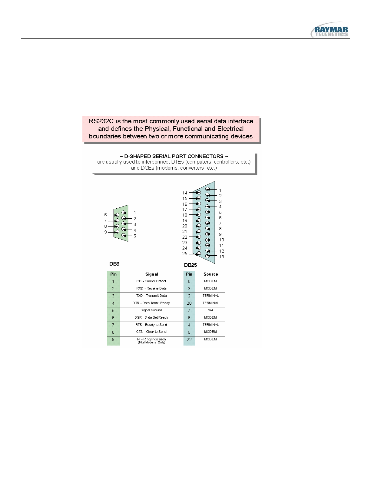
8. SERIAL DATA PORT PIN-OUTS
0049-0867-01X 2nd Generation MIU14.4L – USER’S GUIDE 6/22/2011
Rev. A Page 10 of 39

9. LED INDICATOR
The MIU has a single LED that will indicate the following conditions:
4 Blinking: POWER ON
4 Steady: MODEM CONNECTED (CARRIER DETECT)
0049-0867-01X 2nd Generation MIU14.4L – USER’S GUIDE 6/22/2011
Rev. A Page 11 of 39

10. OUTLINE DRAWING & MOUNTING
Mounting Options:
Part Number Description
MIU/DIN Optional DIN Mounting Clip
0049-0867-01X 2nd Generation MIU14.4L – USER’S GUIDE 6/22/2011
Rev. A Page 12 of 39

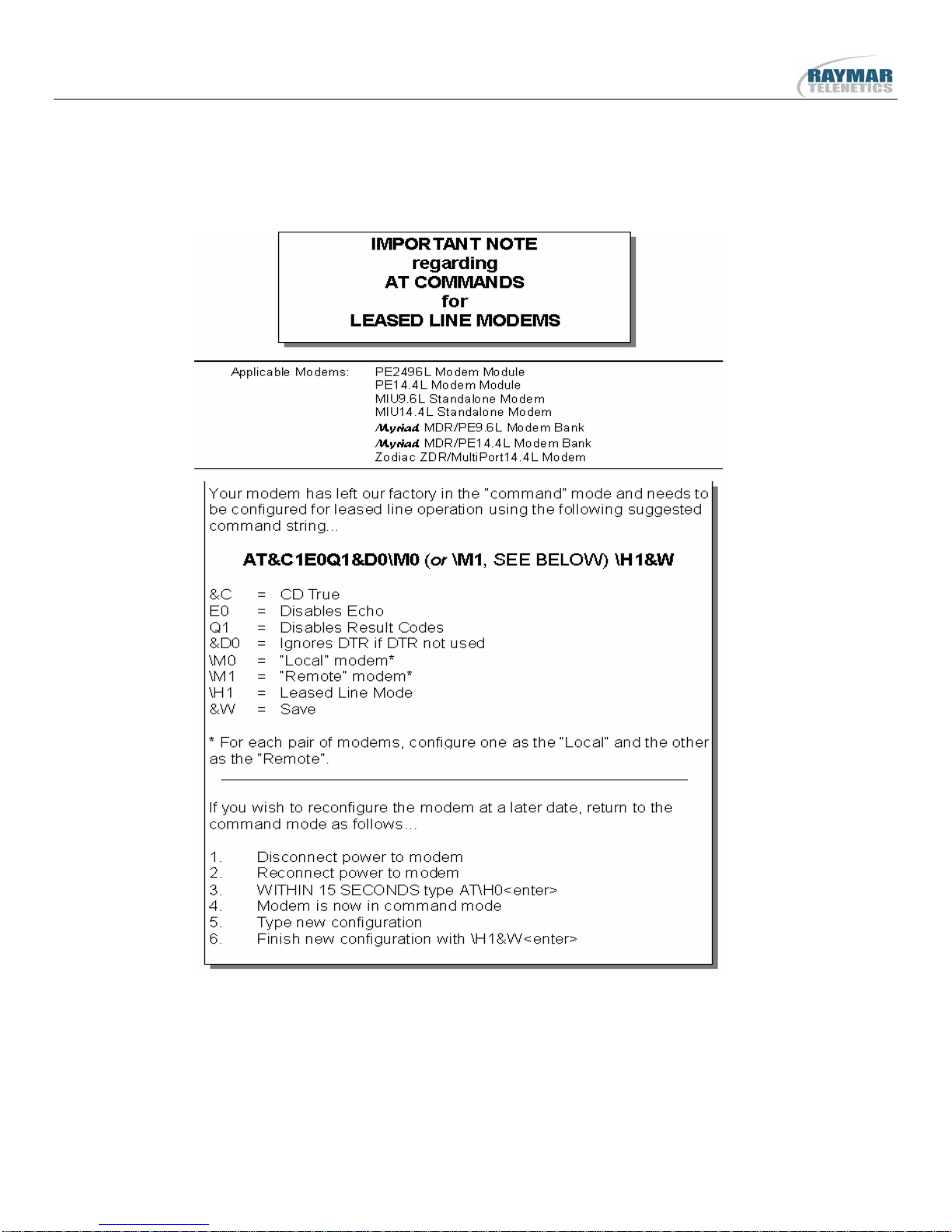
11. MODEM CONFIGURATION
Raymar-Telenetics leased line modems are based on Rockwell chipsets. These chipsets contain
Rockwell’s “AT” command set.
Unless otherwise specified at the time of order, your modem will have left the RaymarTelenetics factory in the configuration detailed on the following pages.
(a) The Raymar-Telenetics factory configuration differs from the Rockwell default
configuration as follows.
&C0 Rockwell Default Carrier Detect (CD) always ON
&C1 Raymar-Telenetics Factory Carrier Detect (CD) only ON when modem
connected (on hook)
(b) Raymar-Telenetics has modified the following Rockwell command
&R0 Rockwell Default CTS follows RTS with a 1ms - 5ms delay
&R0 Raymar-Telenetics CTS follows RTS with no delay
Modification
(c) Raymar-Telenetics has added the following new AT Command to the MIU14.4L
Dumb Mode Feature (\S0, \S1)
In Dumb Mode, the modem will not respond to any received data, including AT commands.
Dumb mode is useful if there is any possibility that a device connected to the modem will try to
send data while the modem is in it’s connect sequence (such data will abort the connection
sequence).
A password must be entered prior to using Dumb Mode. Modems are shipped without a
password. To record a password, enter AT&Z3=password&W<enter> (substitute your
preference for “password”, it is case sensitive).
To enter dumb mode, type ATpassword<enter>, followed by AT\S1<enter>. (This entire
sequence must be entered within 10 seconds).
To exit dumb mode there are two possible methods:
1. Enter ATpassword<enter>, then AT\S0<enter>, within 10 seconds.
2. Power modem off, power on, you have 20 seconds to enter ATpassword<enter>,
then AT\S0<enter>
0049-0867-01X 2nd Generation MIU14.4L – USER’S GUIDE 6/22/2011
Rev. A Page 13 of 39

General
You can review the configuration of your modem by entering AT&V <enter>.
You can restore the Rockwell factory configuration by entering AT&F&W
0049-0867-01X 2nd Generation MIU14.4L – USER’S GUIDE 6/22/2011
Rev. A Page 14 of 39

12. FACTORY CONFIGURATION
ACTIVE PROFILE:
B1 E1 L1 M1 N1 Q0 T V1 W0 X4 Y0 &C1 &D2 &G0 &J0 &K3
&Q5 &R1 &S0 &T5 &X0 &Y0 S00:001 S01:000 S02:043 S03:013
S04:010 S05:008 S06:002 S07:050 S08:002 S09:006 S10:014
S11:095 S12:050 S18:000 S25:005 S26:001 S36:007 S37:000
S38:020 S44:020 S46:138 S48:007 S95:000
STORED PROFILE 0:
B1 E1 L1 M1 N1 Q0 T V1 W0 X4 Y0 &C1 &D2 &G0 &J0 &K3
&Q5 &R1 &S0 &T5 &X0 S00:001 S02:043 S06:002 S07:050
S08:002 S09:006 S10:014 S11:095 S12:050 S18:000 S36:007
S37:000 S40:168 S41:195 S46:138 S95:046
STORED PROFILE 1:
B1 E1 L1 M1 N1 Q0 T V1 W0 X4 Y0 &C1 &D2 &G0 &J0 &K3
&Q5 &R1 &S0 &T5 &X0 S00:001 S02:043 S06:002 S07:050
S08:002 S09:006 S10:014 S11:095 S12:050 S18:000 S36:007
S37:000 S40:168 S41:195 S46:138 S95:000
TELEPHONE NUMBERS:
0= 1=
2= 3=
0049-0867-01X 2nd Generation MIU14.4L – USER’S GUIDE 6/22/2011
Rev. A Page 15 of 39
0049-0867-01X 2nd Generation MIU14.4L – USER’S GUIDE 6/22/2011
Rev. A Page 16 of 39

13. AT COMMAND SET and S-REGISTERS
Raymar-Telenetics leased line modems are based on Rockwell chipsets. These chipsets contain
Rockwell's "AT" command set.
A summary of the Rockwell command set for the PE9.6L and PE14.4L Pony Express modem
modules is provided on the following pages.
A Pony Express Modem Module is at the heart of all Raymar-Telenetics modems, including the
following:
MIU9.6L.........................................................PE9.6L
MIU14.4L.....................................................PE14.4L
MIU/PowerPort9.6L.....................................PE9.6L
MIU/PowerPort14.4L.................................PE14.4L
Myriad MDR/PE9.6L ..................................PE9.6L
Myriad MDR/PR14.4L...............................PE14.4L
Zodiac ZDR/MultiPort14.4L .....................PE14.4L
Contact Raymar-Telenetics for more detailed information on AT Commands and S-Registers.
0049-0867-01X 2nd Generation MIU14.4L – USER’S GUIDE 6/22/2011
Rev. A Page 17 of 39

SUMMARY OF THE ROCKWELL "AT" COMMAND SET
To communicate using the modem, use an asynchronous communication program. The command set for
the Raymar-Telenetics modems is compatible with the Hayes command set.
The modem is controlled and configured by the AT (attention command). Each command consists of the
following elements (with the exception of the A/ and the +++ command that will be discussed later).
1. The two character sequence AT
2. A command
3. A command parameter
4. A carriage return
A command is not entered until a carriage return <ENTER> is entered. Spaces entered are ignored. For
example, to enter the command ‘Answer’, type ATA and <ENTER>.
Some commands do not have parameters. Any missing parameters in a command are assigned the value
zero, which may be a valid parameter for the command. The sequence followed by AT command causes
the modem to enter a command state. That is, AT without a command serves as a wake up code and an
"OK" appears on the screen.
The modem queues commands in a 40-character command line. The command line begins with AT and
can have several commands. A separator is not required between the commands.
The command line format is the "AT" prefix, followed by the required commands from the attached list
and terminated with a Carriage Return.
When a carriage return is received, the commands are performed in the order in which they are sent to the
modem. If more than 40 characters are sent to the modem, an error occurs and all commands must be reentered.
0049-0867-01X 2nd Generation MIU14.4L – USER’S GUIDE 6/22/2011
Rev. A Page 18 of 39

BASIC AT COMMANDS for the PE9.6L & PE14.4L MODEM MODULES
Command Function
A/ Re-execute command.
A Go off-hook and attempt to answer a call.
B0 Select V.22 connection at 1200 bps.
B1 Select Bell 212A connection at 1200 bps.
C1 Return OK message.
Dn Dial modifier.
E0 Turn off command echo.
E1 Turn on command echo.
F0 Select auto-detect mode (equivalent to N1).
F1 Select V.21 or Bell 103.
F2 Reserved.
F3 Select V.23 line modulation.
F4 Select V.22 or Bell 212A 1200 bps line speed.
F5 Select V.22 bis line modulation.
F6 Select V.32 bis or V.32 4800 line modulation (PE14.4L)
F7 Select V.32 bis 7200 line modulation.
F8 Select V.32 bis or V.32 9600 line modulation.
F9 Select V.32 bis 12000 line modulation.
F10 Select V.32 bis 14400 line modulation.
H0 Initiate a hang-up sequence.
H1 If on-hook, go off-hook and enter command mode.
I0 Report product code.
I1 Report pre-computed checksum.
I2 Report OK.
I3 Report firmware revision, model, and interface type.
I4 Report response "Telenetics Inc. Rev"
I5 Report the country code parameter.
I6 Report modem data pump model and code revision.
I7 Reports the DAA code
L0 Set low speaker volume.
L1 Set low speaker volume.
L2 Set medium speaker volume.
L3 Set high speaker volume.
M0 Turn speaker off.
M1 Turn speaker on during handshaking and turn speaker off while receiving carrier.
M2 Turn speaker on during handshaking and while receiving carrier.
M3 Turn speaker off during dialing and receiving carrier and turn speaker on during answering.
0049-0867-01X 2nd Generation MIU14.4L – USER’S GUIDE 6/22/2011
Rev. A Page 19 of 39

N0 Turn off automode detection.
N1 Turn on automode detection.
O0 Go on-line.
O1 Go on-line and initiate a retrain sequence.
P Force pulse dialing.
Q0 Allow result codes to DTE.
Q1 Inhibit result codes to DTE.
Sn Select S-Register as default.
Sn? Return the value of S-Register n.
=v Set default S-Register to value v.
? Return the value of default S-Register.
T Force DTMF dialing.
V0 Report short form (terse) result codes.
V1 Report long form (verbose) result codes.
W0 Report DTE speed in EC mode.
W1 Report line speed, EC protocol and DTE speed.
W2 Report DCE speed in EC mode.
X0 Report basic call progress result codes, i.e., OK, CONNECT, RING, NO CARRIER (also, for busy, if
enabled, and dial tone not detected),NO ANSWER and ERROR.
X1 Report basic call progress result codes and connections speeds (OK, CONNECT, RING, NO
CARRIER (also, for busy, if enabled, and dial tone not detected), NO ANSWER, CONNECT XXXX,
and ERROR.
X2 Report basic call progress result codes and connections speeds, i.e., OK, CONNECT, RING, NO
CARRIER (also, for busy, if enabled, and dial tone not detected), NO ANSWER, CONNECT XXXX,
and ERROR.
X3 Report basic call progress result codes and connection rate, i.e., OK, CONNECT, RING, NO
CARRIER, NO ANSWER, CONNECT XXXX, BUSY, and ERROR.
X4 Report all call progress result codes and connection rate, i.e., OK, CONNECT, RING, NO
CARRIER, NO ANSWER, CONNECT XXXX, BUSY, NO DIAL TONE and ERROR.
Y0 Disable long space disconnect before on-hook.
Y1 Enable long space disconnect before on-hook.
Z0 Restore stored profile 0 after warm reset.
Z1 Restore stored profile 1 after warm reset.
&C0 Force RLSD active regardless of the carrier state.
&C1 Allow RLSD to follow the carrier state.
0049-0867-01X 2nd Generation MIU14.4L – USER’S GUIDE 6/22/2011
Rev. A Page 20 of 39

&D0 Interpret DTR ON-to-OFF transition per &Qn:
&Q0, &Q5, &Q6 The modem ignores DTR.
&Q1, &Q4 The modem hangs up.
&Q2, &Q3 The modem hangs up.
&D1 Interpret DTR ON-to-OFF transition per &Qn:
&Q0, &Q1, &Q4,.
&Q5, &Q6 Asynchronous escape.
&Q2, &Q3 The modem hangs up.
&D2 Interpret DTR ON-to-OFF transition per &Qn:
&Q0 through &Q6 The modem hangs up.
&D3 Interpret DTR ON-to-OFF transition per &Qn:.
&Q0, &Q1, &Q4,.
&Q5, &Q6 The modem performs soft reset.
&Q2, &Q The modem hangs up.
&F0 Restore factory configuration 0.
&F1 Restore factory configuration 1.
&G0 Disable guard tone.
&G1 Disable guard tone.
&G2 Enable 1800 Hz guard tone.
&J0 Set S-Register response only for compatibility.
&J1 Set S-Register response only for compatibility.
&K0 Disable DTE/DCE flow control.
&K3 Enable RTS/CTS DTE/DCE (Hardware) flow control.
&K4 Enable XON/XOFF DTE/DCE (Software) flow control.
&K5 Enable transparent XON/XOFF flow control.
&K6 Enable both RTS/CTS and XON/XOFF flow control.
&L0 Select dial up line operation.
&L1 Select leased line operation.
* Serial interface operation only.
&M0 Select direct asynchronous mode.
&M1 Select sync connect with async off-line command mode. *
&M2 Select sync connect with async off-line command mode and enable DTR dialing of directory zero. *
&M3 Select sync connect with async off-line command mode and enable DTR to act as Talk/Data switch. *
&P0 Set 10 pps pulse dial with 39%/61% make/break.
&P1 Set 10 pps pulse dial with 33%/67% make/break.
&P2 Set 20 pps pulse dial with 39%/61% make/break.
&P3 Set 20 pps pulse dial with 33%/67% make/break.
&Q0 Select direct asynchronous mode.
&Q1 Select sync connect with Async off-line command mode. *
&Q2 Select sync connect with Async off-line command mode and enable DTR dialing of directory zero. *
&Q3 Select sync connect with Async off-line command mode and enable DTR to act as Talk/Data switch. *
&Q4 Select Hayes AutoSync mode.
&Q5 Modem negotiates an error-corrected link.
&Q6 Select asynchronous operation in normal mode.
0049-0867-01X 2nd Generation MIU14.4L – USER’S GUIDE 6/22/2011
Rev. A Page 21 of 39

&R0 CTS tracks RTS (Async) or acts per V.25 (sync).
&R1 CTS is always active.
&S0 DSR is always active.
&S1 DSR acts per V.25.
&T0 Terminate any test in progress.
&T1 Initiate local analog loopback.
&T2 Returns ERROR result code.
&T3 Initiate local digital loopback.
&T4 Allow remote digital loopback.
&T5 Disallow remote digital loopback request.
&T6 Request an RDL without self-test.
&T7 Request an RDL with self-test.
&T8 Initiate local analog loop with self-test.
&V Display current configurations.
&W0 Store the active profile in NVRAM profile 0.
&W1 Store the active profile in NVRAM profile 1.
&X0 Select internal timing for the transmit clock.
&X1 Select external timing for the transmit clock.
&X2 Select slave receive timing for the transmit clock.
&Y0 Recall stored profile 0 upon power up.
&Y1 Recall stored profile 1 upon power up.
&Zn=x Store dial string x (to 35) to location n (0 to 3 depending upon modem model).
%E0 Disable line quality monitor and auto retrain.
%E1 Enable line quality monitor and auto retrain.
%E2 Enable line quality monitor and fallback/fall forward.
%L Return received line signal level.
%Q Report the line signal quality.
\D1 Enable Auto Dial via DTR off to on sequence *PE14400 only
\D0 Disable Auto Dial (default) *PE14400 only
\G0 Disable modem to modem flow control.
\G1 Enable modem to modem flow control.
\H0 Command Mode default
\H1 Lease Line Mode
0049-0867-01X 2nd Generation MIU14.4L – USER’S GUIDE 6/22/2011
Rev. A Page 22 of 39

\Kn Controls break handling during three states:
When modem receives a break from the DTE:
\K0,2,4 Enter on-line command mode, no break sent to the remote modem.
\K1 Clear buffers and send break to remote modem.
\K3 Send break to remote modem immediately.
\K5 Send break to remote modem in sequence with transmitted data.
When modem receives \B in on-line command state:
\K0,1 Clear buffers and send break to remote modem.
\K2,3 Send break to remote modem immediately.
\K4,5 Send break to remote modem in sequence with transmitted data.
When modem receives break from the remote modem:
\K0,1 Clear data buffers and send break to DTE.
\K2,3 Send a break immediately to DTE.
\K4,5 Send a break with received data to the DTE.
\M0 Select Answer Mode (Lease Line) with \H1 active
\M1 Select Originate Mode (Lease Line) with \H1 active
\N0 Select normal speed buffered mode.
\N1 Select direct mode.
\N2 Select reliable link mode.
\N3 Select auto reliable mode.
\N4 Force LAPM mode.
\N5 Force MNP mode.
\S0 Unlock command mode (normal mode) *PE14400 only
\S1 Lock (out) command mode (security mode) *PE14400 only
ECC COMMANDS
%C0 Disable data compression.
%C1 Enable MNP 5 data compression.
%C2 Enable V.42 bis data compression.
%C3 Enable both V.42 bis and MNP 5 compression.
\A0 Set maximum block size in MNP to 64.
\A1 Set maximum block size in MNP to 128.
\A2 Set maximum block size in MNP to 192.
\A3 Set maximum block size in MNP to 256.
\Bn Send break of n x 100 ms.
0049-0867-01X 2nd Generation MIU14.4L – USER’S GUIDE 6/22/2011
Rev. A Page 23 of 39
S-Register Summary
Register Function Range Units Save Default*
*
S0 Rings to
Auto-Answer
S1 RING COUNTER 0-255 Rings 0
S2 ESCAPE
CHARACTER
S3 Carriage Return
Character
S4 Line Feed
Character
S5 Backspace
Character
S6 Wait time for Dial
Tone
S7 Wait time for
Carrier
0-255 Rings * 0
0-255 ASCII * 43
0-127 ASCII 13
0-127 ASCII 10
0-255 ASCII 8
2-255 S * 2
1-255 s * 50
S8 Pause Time for
Dial Delay Modifier
S9 Carrier Detect
Response Time
S10 Carrier Loss
Disconnect Time
S11 DTMF Tone
Duration
S12 Escape Code
Guard Time
S13 Reserved - - - -
S14 General Bit
Mapped
S15 Reserved _ - - -
0049-0867-01X 2nd Generation MIU14.4L – USER’S GUIDE 6/22/2011
Rev. A Page 24 of 39
0-255 s * 2
1-255 0.1 s * 6
1-255 0.1 s * 14
50-255 0.01 s * 95
0-255 0.02 s * 50
- - * 138
(8Ah)

Register Function Range Units Save Default*
*
S16 Test Mode Bit
- - - 0
Mapped option
(&T)
S17 Reserved - - - -
S18 Test Timer 0-255 s * 0
S19-S20 Reserved - - - -
S21 V.24/General Bits
- - * 4 (04h)
Opt.
S22 Speaker/Results - - * 117
S23 General Bit
- - * 55 (35h)
Mapped Options
S24 Sleep Inactivity
0-255 s * 0
Timer
S25 Delay to DTR Off 0-255 s or
* 0
0.01 s
S26 RTS to CTS Delay 0-255 0.01 s 1
S27 General Bit-
- - * 73 (49h)
Mapped Options
S28 General Bit-
- - * 0
Mapped Options
S29 Flash Dial Modifier
0-255 10ms 0
Time
S30 Disconnet Inactivity
0-255 10s 0
Time
S31 General Bit-
- - * 2
Mapped Options
S32 XON Character 0-255 ASCII 17 (11h)
S33 XOFF Character 0-255 ASCII 19 (13h)
S34-S35 Reserved - - -
0049-0867-01X 2nd Generation MIU14.4L – USER’S GUIDE 6/22/2011
Rev. A Page 25 of 39

Register Function Range Units Save Default*
*
S36 LAPM Failure
- - * 7
Control
S37 Line Connection
- - * 0
Speed
S38 Delay before
0-255 s 20
Forced Hangup
S39 Flow Control - - * 3
S40 General Bit-
- - * 105 (69)
Mapped Options
S41 General Bit-
- - * 3
Mapped Options
S42-S45 Reserved - - -
S46 Data Compression
- - * 138
Control
S48 V.42 Negotiation
- - * 7
Control
S80 Soft-Switch
- - 0
Functions
S82 LAPM Break
Control
S86 Call Failure
- - 128
(40h)
0-255 - -
Reason Code
S95 Result Code
- - * 0
Messages Control
0049-0867-01X 2nd Generation MIU14.4L – USER’S GUIDE 6/22/2011
Rev. A Page 26 of 39

14. DIAGNOSTICS
The following pages provide software and hardware techniques for diagnosing communication
problems and thereby isolating the problem at either the local modem, the remote modem or the
interconnecting line.
The following AT&Tn commands form part of the CCITT V.54 protocol and can be used for
diagnostic testing.
Note: &Tn commands can only be used when the modem is configured for &Q0 <CR>
(unbuffered/direct asynchronous mode).
&T0 TERMINATE TEST IN PROGRESS
If a V.54 loopback test is in progress as a result of executing an &Tn command, then the &T0
command will cause that test to be terminated, provided that the modem is in the command state or
a V.54 state that accepts commands from the DTE. See specific &Tn command descriptions for
termination actions.
&T1 INITIATE LOCAL ANALOG LOOPBACK (See Figure 2)
When the AT&T1 command is entered, the modem goes on hook and configures itself for analog
loopback. DSR is turned off (if &S1 is in effect), the analog loopback state is entered, and the test
timer is set to the value in S18. A connect result code is sent to the DTE, and the test timer then
begins its count down. The test terminates when the test timer expires. If S18 equals 0, then the
test must be terminated by an &T0, H0, or Z command. While any command may be entered
while the modem is in this test state, the modem response is not specified except for H0, &T0 and
Z, any of which will terminate the test. Upon termination of the test, the modem enters the
command state.
RESULT CODE DESCRIPTION
CONNECT When local analog loopback state is entered.
ERROR If any other &Tn test is active (except &T0) or if in the on-line command
state.
OK After test is stopped by test timer, the H0 command, or the &T0 command.
0049-0867-01X 2nd Generation MIU14.4L – USER’S GUIDE 6/22/2011
Rev. A Page 27 of 39

&T2 NO FUNCTION
&T3 PERFORM LOCAL DIGITAL LOOPBACK (See Figure 3)
The modem must be in the command state with connection established when this command is
issued, otherwise an ERROR result code occurs.
The AT&T3 command establishes a loopback of received data, after demodulation, and sends it
back to the distant end. The modem is configured for local digital loopback, DSR is turned off (if
&S1 is in effect), the test timer is started with the value in S18, and an OK result code is sent to the
DTE. If S18 contains a 0, the test must be terminated by an &T0, H0, or Z command. The latter
two result in the modem going on hook. If S18 does not contain 0, the test is terminated after the
number of seconds stored in S18.
RESULT CODE DESCRIPTION
OK After 2 second delay
ERROR If any other self test is active (&T1, &T6, &T7 or &T8) or if in idle state.
When test is terminated.
&T4 GRANT REMOTE DIGITAL LOOPBACK (RDL) REQUESTS
When in the on-line state, the modem will honor a remote digital loopback request from a distant
modem if it occurs. This will result in an ERROR if the command is given while any V.54 test is
active (&T1, &T3, &T6, &T7 or &T8).
NOTE: There are data patterns that may cause Remote Digital Loopback conditions. Care should
be given to the type of data being received so that no RDL modes will be initiated.
0049-0867-01X 2nd Generation MIU14.4L – USER’S GUIDE 6/22/2011
Rev. A Page 28 of 39

&T5 DENY RDL REQUESTS
The modem will not respond to a remote digital loopback request from a distant modem. This
will result in an error if the command is given while any V.54 test is active (&T1, &T3, &T6,
&T7 or &T8).
&T6 INITIATE REMOTE DIGITAL LOOPBACK (See Figure 4)
The command is valid only if the modem is in the command state with a connection established.
Configure the modem under test with an AT&T4 command so that it will honor a remote digital
loopback request.
Enter AT&T6 at the local modem and it will send a remote digital loopback request to the remote
modem. After the RDL acknowledgement signal is received from the remote modem, DSR is
turned off (if &S1 is in effect), the on-line state is entered, a CONNECT result code is sent to the
DTE, and the test timer is set to the value in S18.
If the local modem does not receive the RDL acknowledgment signal from the remote end in
three seconds, it sends an ERROR result code to the DTE and returns to the command state. The
local modem sends the signal to release the remote digital loopback when the test is terminated.
The test may be terminated by the H0, Z, or &T0 command. The test will also terminate when the
test timer expires (sending the modem to the command state) or carrier is lost (causing a NO
CARRIER result code and the modem to go on hook in the command state).
RESULT CODE DESCRIPTION
CONNECT When on-line state is entered.
ERROR If any V.54 test is active (&T1, &T3, &T6 - &T8).
ERROR If not in on-line command state.
ERROR If the RDL signal is not acknowledged.
0049-0867-01X 2nd Generation MIU14.4L – USER’S GUIDE 6/22/2011
Rev. A Page 29 of 39

&T7 INITIATE RDL WITH LOCAL SELF TEST (See Figure 5)
This is a system test, end to end.
The command is valid only if the modems are in the command state with a connection
established.
Configure the remote modem with an AT&T4 command so that it will honor a remote digital
loopback request.
Enter AT&T7 at the local modem and it will send a digital loopback request to the remote
modem. After the RDL acknowledgment signal is received from the remote modem, DSR is
turned off (if &S1 is in effect), the on-line state is entered, an OK result code is sent to the DTE,
and the test timer is set to the value in S18. While the test is active, the local modem sends a test
message to the remote modem and counts the errors in the received (looped back) signal. The
modems stay in the command state during the test. When the test is terminated (except by a loss
of carrier), the local modem sends the release signal to the remote modem, as in &T6, and reports
the three-digit error count to the DTE.
The information text is followed by an OK result code. The test is terminated by loss of carrier,
or an H0, &T0, or Z command, and by the S18 timer running out.
RESULT CODES DESCRIPTION
OK When command executed is started.
OK After error count is sent to DTE (&T1,
&T3, &T6, &T7 or &T8).
ERROR If not in on-line command state.
ERROR If the RDL signal is not acknowledged.
0049-0867-01X 2nd Generation MIU14.4L – USER’S GUIDE 6/22/2011
Rev. A Page 30 of 39

&T8 LOCAL LOOPBACK WITH SELF TEST (See Figure 6)
The modem should be on hook. Enter AT&T8 to configure the modem for analog loopback and
self test. The test timer is started at the time indicated by S18, DSR is turned off (if &S1 is in
effect). A self test condition is entered, and an OK result code is sent to the DTE. During the test
the modem sends a test message and counts errors in the looped back signal. The test is
terminated when the timer times out (S18) or the &T0, H0, or Z command is issued. When the
test is terminated, the three digit error count is sent to the DTE. An OK result code follows the
error count.
RESULT CODE DESCRIPTION
OK If a test state is entered.
OK After error count is sent to DTE
ERROR If any other V.54 test is active (&T1, &T3, &T6, &T7), or if on-line.
0049-0867-01X 2nd Generation MIU14.4L – USER’S GUIDE 6/22/2011
Rev. A Page 31 of 39

0049-0867-01X 2nd Generation MIU14.4L – USER’S GUIDE 6/22/2011
Rev. A Page 32 of 39

0049-0867-01X 2nd Generation MIU14.4L – USER’S GUIDE 6/22/2011
Rev. A Page 33 of 39

0049-0867-01X 2nd Generation MIU14.4L – USER’S GUIDE 6/22/2011
Rev. A Page 34 of 39

ADDITIONAL TEST / DIAGNOSTICS COMMANDS
%L RECEIVED SIGNAL LEVEL
Returns a value (-dBm) which indicates the received signal level at modem DATA PUMP
interface. This value is determined by the loss/gain of modem Telco Interface circuit ±dB at the
Tip/Ring input to the modem. Typical value should be -25dBm to -35dBm for most Telco
connections.
%Q RECEIVED LINE SIGNAL QUALITY
Reports the line signal quality at the modem DATA PUMP interface. This signal is also
dependent on the DAA circuit (Telco Interface). Returns the higher order byte of the EQM (Eye
Quality Monitor is the filter squared magnitude of the error vector). Typical value should be
below 10. The lower the number, the better the performance from the modem.
ERROR response if NO connection to remote modem.
In &T1, modem %Q will be 0.
S86 CONNECTION FAILURE CAUSE
S86 can help determine the cause of a connection failure. When the modem issues a NO
CARRIER result code, a value is written to this register. To read this register, following the
connection failure, issue ATS86? <CR>. The modem will report one of the following values:
0 Normal hang up; no error occurred.
4 Physical carrier loss. (Loss of Carrier)
5 Feature negotiation failed to detect presence of another V.42 error-control modem at other end.
6 Other error-control modem did not respond to feature negotiation message sent by this modem.
7 Other modem is synchronous-only; this modem is asynchronous-only.
8 Modems could not find a common framing technique.
9 Modems could not find a protocol in common.
10 Feature negotiation message sent by other modem incorrect.
11 Synchronous information (data of flags) not received from other modem.
12 Normal disconnect initiated by other modem.
0049-0867-01X 2nd Generation MIU14.4L – USER’S GUIDE 6/22/2011
Rev. A Page 35 of 39

13 Other modem did not respond after many transmissions of the same message. Modem made 10
attempts then hung up.
14 Protocol violation occurred.
15 Compression failure.
Note: Multiple occurrences may contribute to a NO CARRIER message; S86 records the first event that
occurred.
0049-0867-01X 2nd Generation MIU14.4L – USER’S GUIDE 6/22/2011
Rev. A Page 36 of 39

NOTES
0049-0867-01X 2nd Generation MIU14.4L – USER’S GUIDE 6/22/2011
Rev. A Page 37 of 39

Raymar Information Technology, Inc.
Limited Warranty
One Year Limited Hardware Warranty
Raymar Information Technology, Inc., dba Raymar-Telenetics, warrants their products against defects in hardware, material and workmanship under normal
use for one (1) year from the date of purchase. Raymar will, at no charge, either repair the product (with new or reconditioned parts), or replace it (with a
new or reconditioned product). Repaired replacement products are warranted for either 90 days or the remainder of the original warranty period, whichever is
longer. This warranty extends to the original end-user only.
What This Warranty Does Not Cover
This warranty does not cover: (a) software; (b) installation or service of the product; (c) conditions resulting from consumer damage such as impr oper
maintenance or misuse, abuse, accident or alteration; (d) all plastic surfaces (including display screens) and all other exposed parts that are scratched or
damaged due to normal use; (e) operation of our pr oducts with equipment not supplied by Raymar (f) products which have had the serial number removed or
made illegible; or (g) products rented to others. This warranty applies only to hardware products manufactured by or for Raymar Information Technology,
Inc. and identified by the Raymar-Telenetics trademark, trade name or product identification logo affixed to them. Refer to the Service and Support section
of the User’s Guide for service after the warranty expires. No warranty is made as to coverage availability or grade of service provided by the carrier.
General Provisions
This warranty sets forth Raymar’s entire hardware responsibilities regarding this product. Repair, replacement or refund of the purchase price is at Raymar’s
discretion. THIS WARRANTY IS GIVEN IN LIEU OF ALL OTHER EXPRESS WARRANTIES, IMPLIED WARRANTIES, INCLUDING WITHOUT
LIMITATION IMPLIED WARRANTIES OF MERCHANTABILITY AND FITNESS FOR A PARTICULAR PURPOSE, AND ARE LIMITED TO THE
DURATION OF THIS LIMITED WARRANTY. IN NO EVENT SHALL RAYMAR BE LIABLE FOR DAMAGES IN EXCESS OF THE PURCHASE
PRICE OF THE PRODUCT, FOR ANY LOSS OF USE, LOSS OF TIME, INCONVENIENCE, COMMERCIAL LOSS, LOST PROFITS OR SAVINGS,
OR OTHER INCIDENTAL, SPECIAL OR CONSEQUENTIAL DAMAGES ARISING OUT OF THE USE OR INABILITY TO USE THIS RAYMAR
PRODUCT, TO THE FULL EXTENT SUCH MAY BE DISCLAIMED BY LAW. WITHOUT LIMITING THE FOREGOING, RAYMAR SHALL HAVE
NO LIABILITY FOR ANY DATA STORED IN OR USED WITH THE PRODUCT, INCLUDING THE RECOVERY COSTS OF SUCH DATA OR
PROGRAMS.
State Law Rights
SOME STATES DO NOT ALLOW THE EXCLUSION OR LIMITATION OF INCIDENTAL OR CONSEQUENTIAL DAMAGES OR LIMITATIONS
ON HOW LONG AN IMPLIED WARRANTY LASTS. THE ABOVE LIMITATIONS OR EXCLUSIONS MAY NOT APPLY TO YOU. This warranty
gives you specific legal rights, and you may also have other rights which vary from State to State.
Provincial Law Rights
SOME PROVINCIAL LAWS DO NOT ALLOW THE EXCLUSION OR LIMITATION OF IMPLIED WARRANTIES, THE
EXCLUSION OR LIMITATION OF WARRANTY COVERAGE IN CERTAIN SITUATIONS. SOME OF THE ABOVE
LIMITATIONS OR EXCLUSIONS CONTAINED IN THIS LIMITED WARRANTY MAY NOT APPLY TO YOU. This warranty gives you specific
rights, and you may have other rights which vary from province to province.
How To Use Raymar’s Limited Warranty Service
To take advantage of this warranty, you must do the following:
• If you are having trouble with your product, contact Raymar service using the appropriate number from the Service and Support
section of the User’s Guide. If it is determined that your product requires service, you will be issued a Return Materials
Authorization (RMA) form.
• Pack the defective product securely for shipping. Include only the units pre-approved by service on your RMA form.
• This warranty is void if the product is damaged in transit, you must insure your shipment.
• Ship the defective product, proof of date of purchase, and the RMA form to the address specified.
• Display your RMA number prominently on the outside of the sh ipping box. Customer is responsible for freight in, door to door. Raymar is responsible for
return shipping costs.
• To ensure prompt service, please write on the RMA form a brief description of the problem you are experiencing with the
product.
Raymar Information Technology, Inc.
7325 Roseville Road
Sacramento, CA 95842
Service Hotline (800) 747-1522
http://support.telenetics.com
or e-mail to techsupport@raymarinc.com
0049-0867-01X 2nd Generation MIU14.4L – USER’S GUIDE 6/22/2011
Rev. A Page 38 of 39

Raymar Information Technology, Inc.
Return Merchandise Authorization (RMA) Procedure
Before returning any Raymar-Telenetics product, an RMA number must be obtained.
The most convenient way to obtain an RMA number for a product purchased from Raymar-Telenetics is
to call 1-800-747-1522. When doing so, please have the following information ready:
- Company name
- Full billing address, as well as the address for the location where the product should be returned
once repaired or replaced
- Telephone & Fax numbers
- Email address
- Product model number and serial number
For each item being returned, please include the product model number, the serial number, a description
of the problem being encountered, and the cause of the problem (if known).
Please note that prior to authorizing a return, a product support specialist may call to verify that the
product is properly installed or may ask you to perform tests to insure that the product has actually
failed.
The product must be properly packed and returned to:
Raymar-Telenetics
7325 Roseville Road
Sacramento, CA 95842
The RMA number must be legibly displayed on the shipping carton. Raymar-Telenetics will not be
responsible for any product returned without an RMA number.
If the product is out of warranty, estimates for repair rates and any applicable shipping costs will be
communicated by a customer service representative. Currently, Raymar-Telenetics accepts purchase
orders or credit cards as payment methods.
Repairs currently require 5 – 10 business days and are returned via UPS Ground.
All repaired products carry a 90-day warranty, beginning from the date they are shipped from Raymar’s
facility.
0049-0867-01X 2nd Generation MIU14.4L – USER’S GUIDE 6/22/2011
Rev. A Page 39 of 39
 Loading...