

Page 1
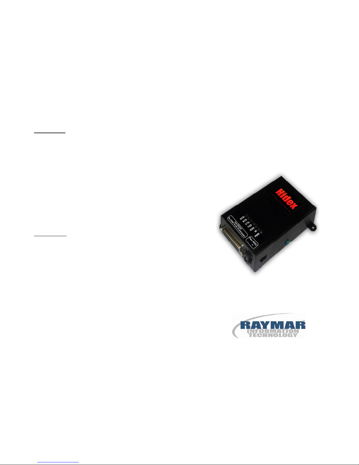
Data Interface
Data is interfaced via a DB25 female connector.
Pin 1 GRD Signal Ground
Pin 2 TXD Transmit Data
Pin 3 RXD Receive Data
Pin 4 RTS Request to Send
Pin 5 CTS Clear to Send
Pin 6 DSR Data Set Ready
Pin 7 GRD Ground
Pin 8 DCD Carrier Detect
Pin 10 (Alternate power input +5VDC)
use switch
Pin 20 DTR Data Terminal Ready
Pin 22 RI Ring Indicate
LED Indicators
DCD Data Carrier Detect
RTS Request to Send
CTS Clear to Send
TXD Transmit Data
RXD Receive Data
RI Ring Indicate
PWR Power indicator (green)
Raymar Information Technology, Inc.
7325 Roseville Road
Sacramento, CA 95842
(800) 695-1951
www.raymarinc.com
Page 4 of 4
HIDEX
QUICK START GUIDE
0049-3400-XX1 Rev. A
Page 2
Hardware Setup
Setup Procedure:
1. Use an RS-232 cable to connect the DB25
connector (J1) on the modem to a PC serial
Port (typically COM1).
2. Connect the RJ11 connector to a phone line.
3. Connect external power +5VDC to the
power jack or via alternate DB25 pins 10 &
7. See the Power Connections section to
ensure correct connector polarity and power
select switch position.
Hyper Terminal Setup
The modem can be tested as a standard serial
data modem by connecting it to a personal computer or other data terminal equipment (DTE).
Any standard terminal program such as HyperTerminal o PCComm running on a PC will communicate with the modem.
Power Connections
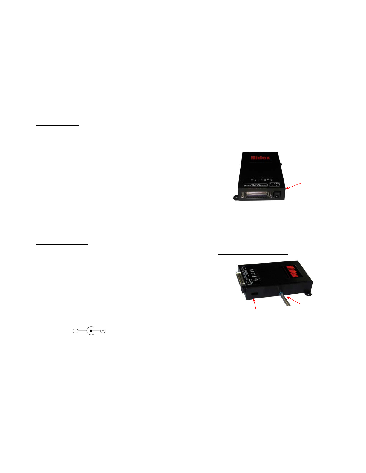
There are two optional methods of supplying
power to the modem. Use the power connector
or via the RS-232 cable. A slide switch on the
side of the case selects which is used.
Included with each modem is the mating connector for the input power. Connect the external
5 VDC power source to the supplied connector
with attention to the +/- polarity of the voltage
source.
CAUTION: NOTE THE POLARITY ON THE
CONNECTOR LABEL.
Page 2 of 4
There is a power input select switch on the side of
the modem nearest the power connector. The
switch is flush or recessed; to select the power
connector input, slide the switch away from the
rear panel.
+5V Power
Input Select
Switch
Page 3 of 4
Alternate power can be connected via the DB25
connector pin #10 for +5VDC and pin #1 or 7 for
ground. To enable this option, move the switch
toward the power connector.
Safety Ground Connection
Pin 10 plus 5VDC and pin 7 ground
+5V Power Input
Select Switch
Ground screw
Use the GREEN case cover screw to connect a
safety ground wire, if desired.
 Loading...