

Rayence RYRWM001A User Manual
PART I. User & Installation Manual
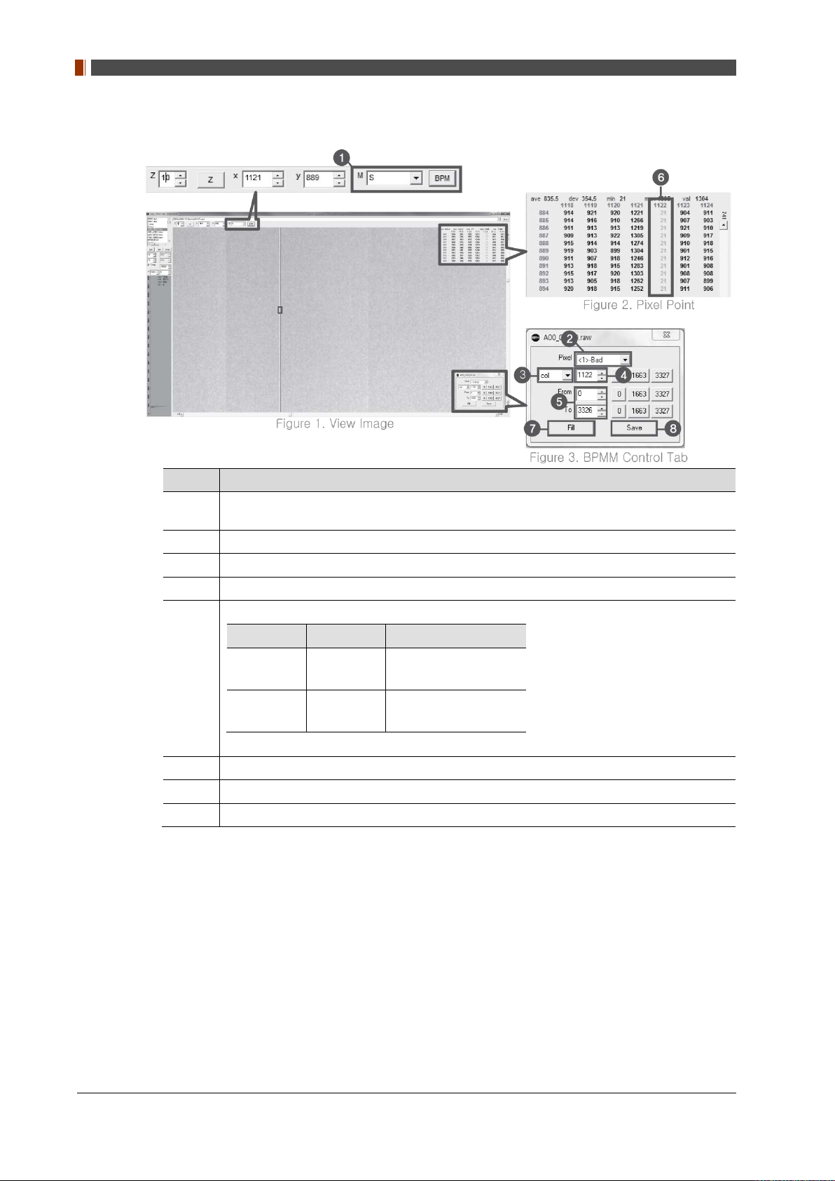
3. Set Manual bad pixel map (BPMM) as below.
No. Overview
At Figure 1, choose S from the list of M(❶) and click "BPM". Check if BPMM window is
1
popped up as Figure 3.
Choose "Bad" from Pixel list (Figure 3 - ❷ ).
2
Choose either “row” or “col” from Figure 3 - ❸.
3
Put the coordinate of pixel to set bad pixel at Figure 3 - ❹.
4
If bad pixel is a line, put the range as below at Figure 3 – ❺.
From To
5
6
7
8
Row 0
Col 0
If bad pixel is not a line but some pixels, put the rest coordinate at Figure 3 - ❺.
After completing step 5 , check if bad pixel has been changed to green as Figure 2 - ❻.
Click “Fill” at Figure 3 - ❼.
Click "Save" at Figure 3 - ❽.
3327(127type)
2449(140type)
2815(127type)
2992(140type)
4. Once setting BPMM is done, “BPMM.raw” file will be saved at C:\Davinci\CAL.
98 1417WGC/WCC
4. Usage
4.1 Set Up
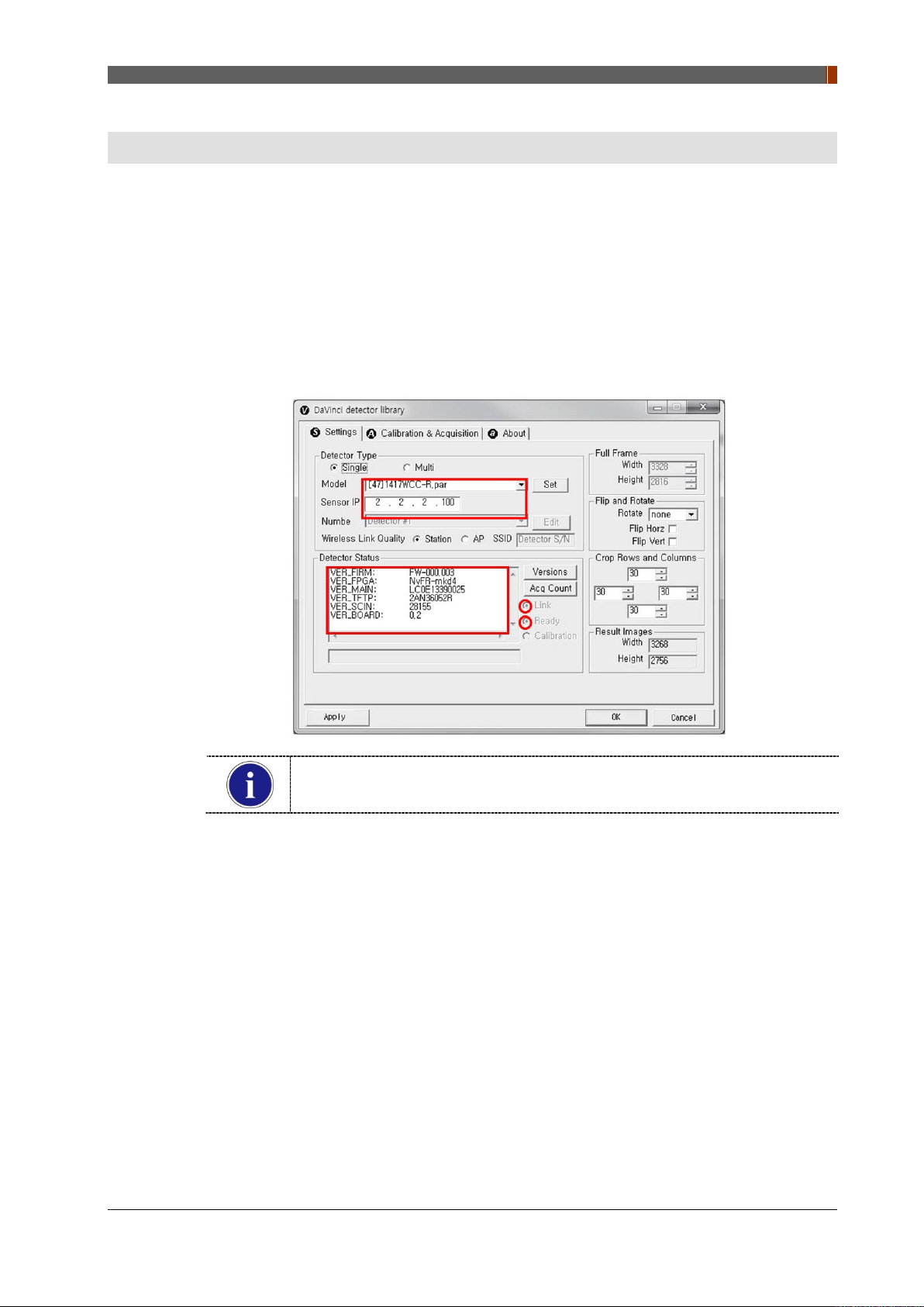
4.1.1 Product Connectivity
1. Connect the detector and turn on the power.
2. Open “_vadav.lnk” from “C:\davinci”.
3. Once the detector is connected, detector information is displayed in Detector Status and
Link & Ready are checked as below.
PART I. User & Installation Manual
If "Detector Status" does not show anything, please refer to 3.1 Installation in
Part.1 User & Installation Manual to connect the detector properly.
1417WGC/WCC 99
PART I. User & Installation Manual
4.1.2 Image Set Up
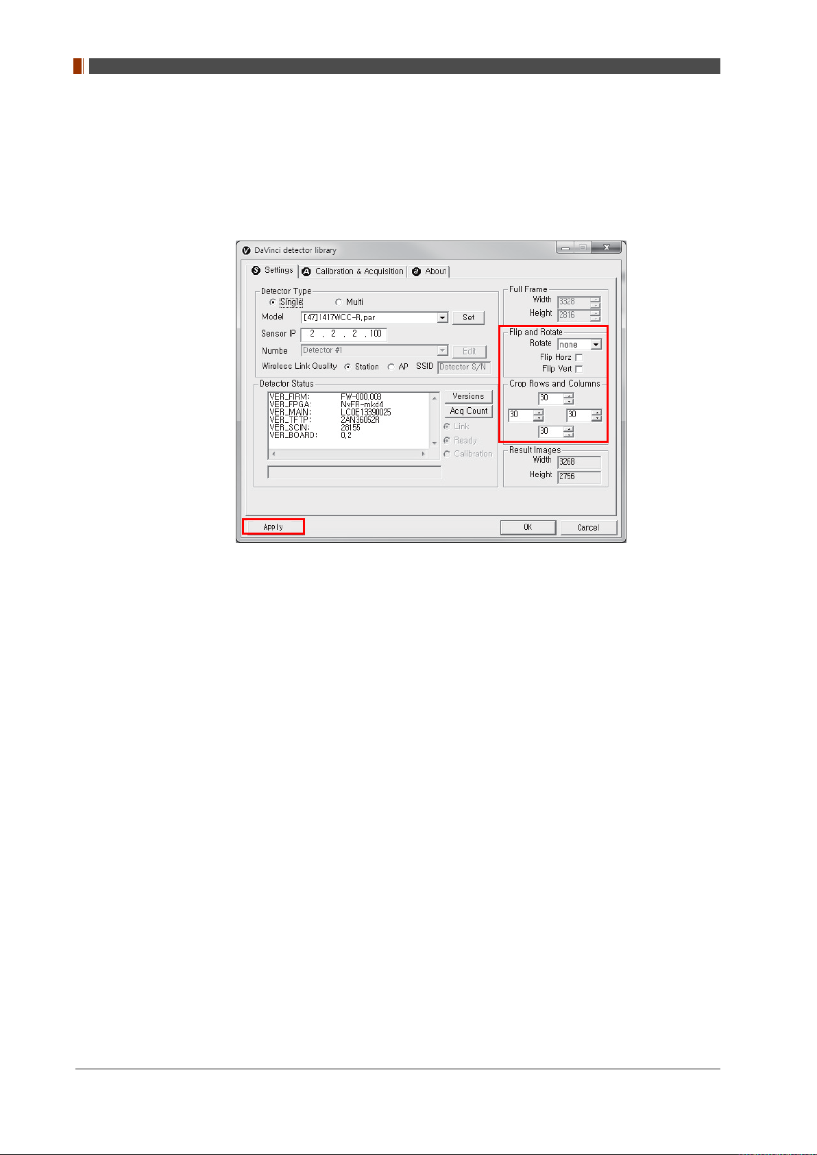
1. In order to rotate or flip an image, use the option of "Flip and Rotate" as shown below.
2. In order to change the size of an image, use "Crop Rows and Columns" as below.
3. Click "Apply" to save.
4.1.3 Multi Detector Set Up
Refer to 3 Multi Detector Set Up in Part.2 Service Manual for Multi-Detector Sett i ng.
100 1417WGC/WCC
4.2 Image Acquisition
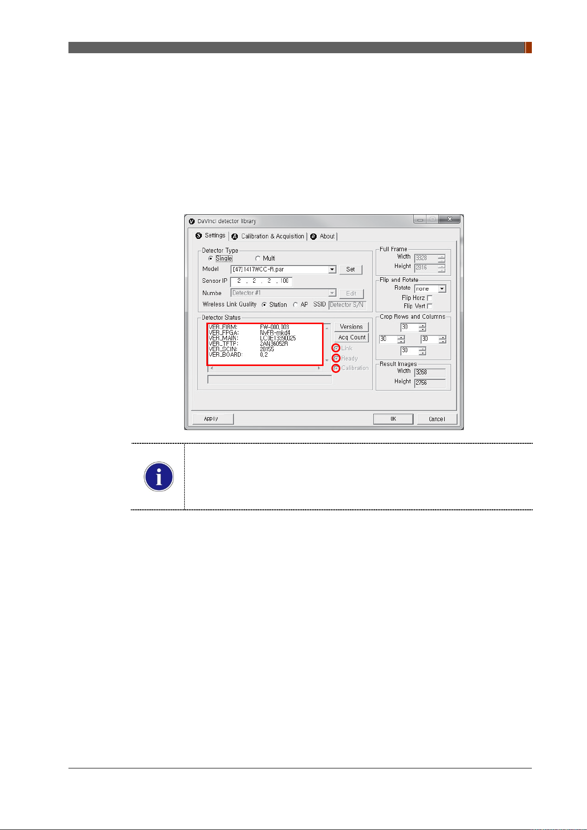
4.2.1 Product Connection
1. Connect the detector and turn on the power.
2. Open “_vadav.lnk” from “C:\davinci”.
3. Once the detector is connected, information of the detector is displayed in Detector Status
and Link & Ready & Calibration are checked as below.
PART I. User & Installation Manual
If "Detector Status" does not show anything, please refer to 3.1 Installation in
Part.1 User & Installation Manual to connect the detector properly.
If Calibration is not checked along with black dots checking off "Link" and "Ready"
as above, please refer to 3.2 Calibration in Part.1 User & Installation Manual and
perform calibration again.
1417WGC/WCC 101
PART I. User & Installation Manual
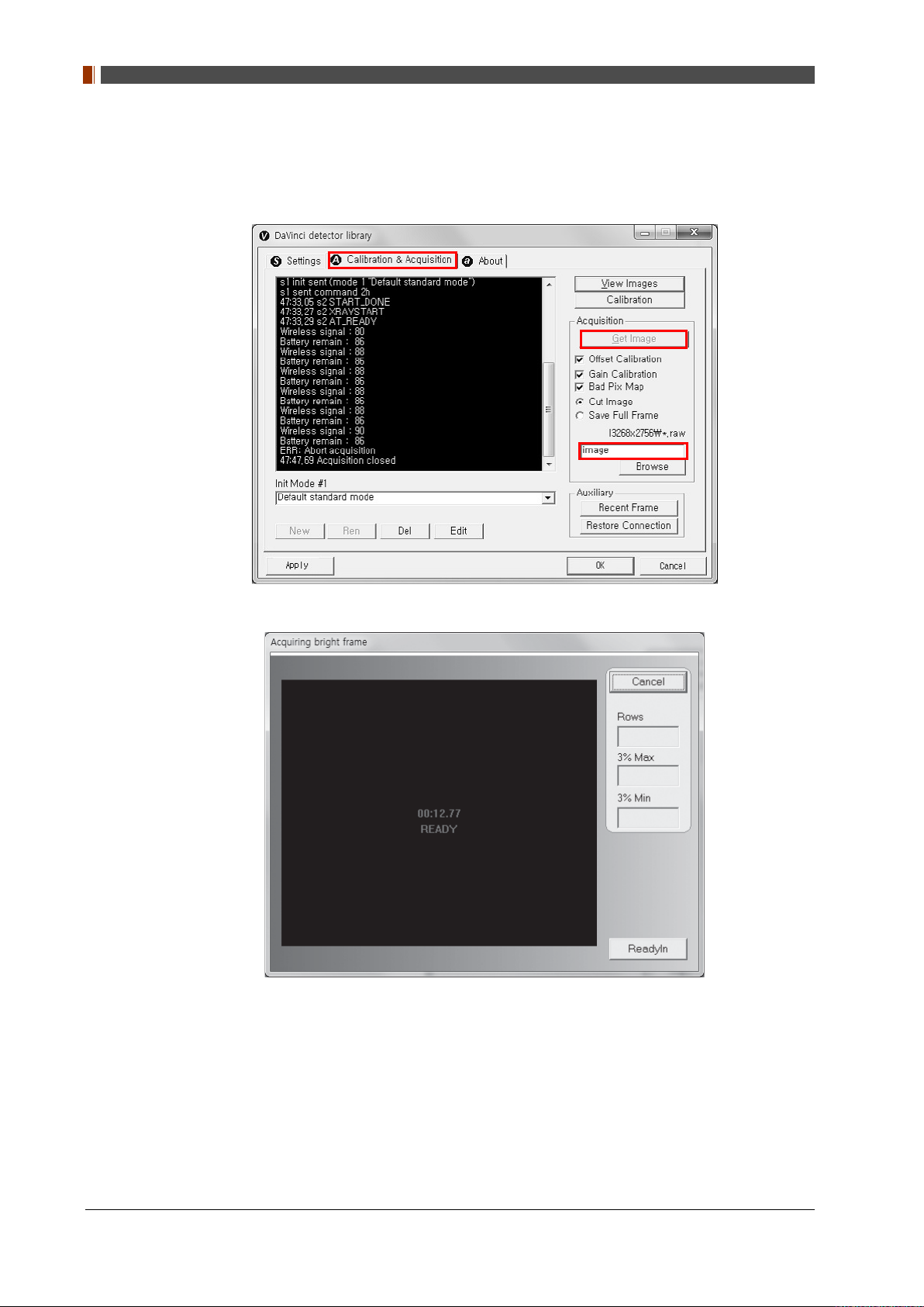
4.2.2 Image Acquisition
1. Click the "Calibration & Acquisition” tab and type the name of the image inside the box
below. After naming the image, click “Get Image”.
2. Shoot an X-ray once the "Acquiring bright frame" window pops up.
3. An acquired image will be stored in “C:\davinci\I.3268x2756 (127type) or 2440x2992
(140type)” and the name of the file will be "(typed name from Step 1).raw”.
4. The format of the stored file is 16 bit little-endian order.
102 1417WGC/WCC
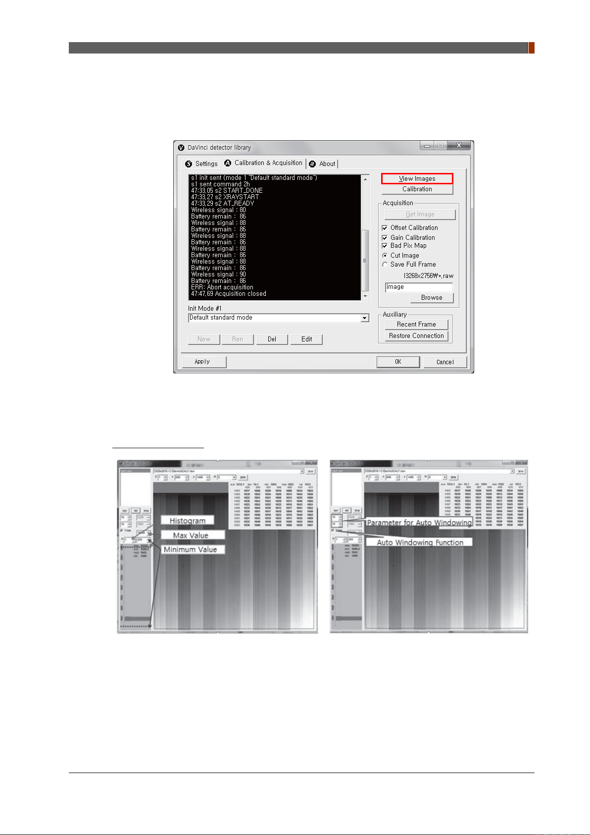
4.3 View Images
1. Click “View Images”
PART I. User & Installation Manual
2. Another wi ndow will be popped up as below.
Histogram Set Up
1417WGC/WCC 103
PART I. User & Installation Manual
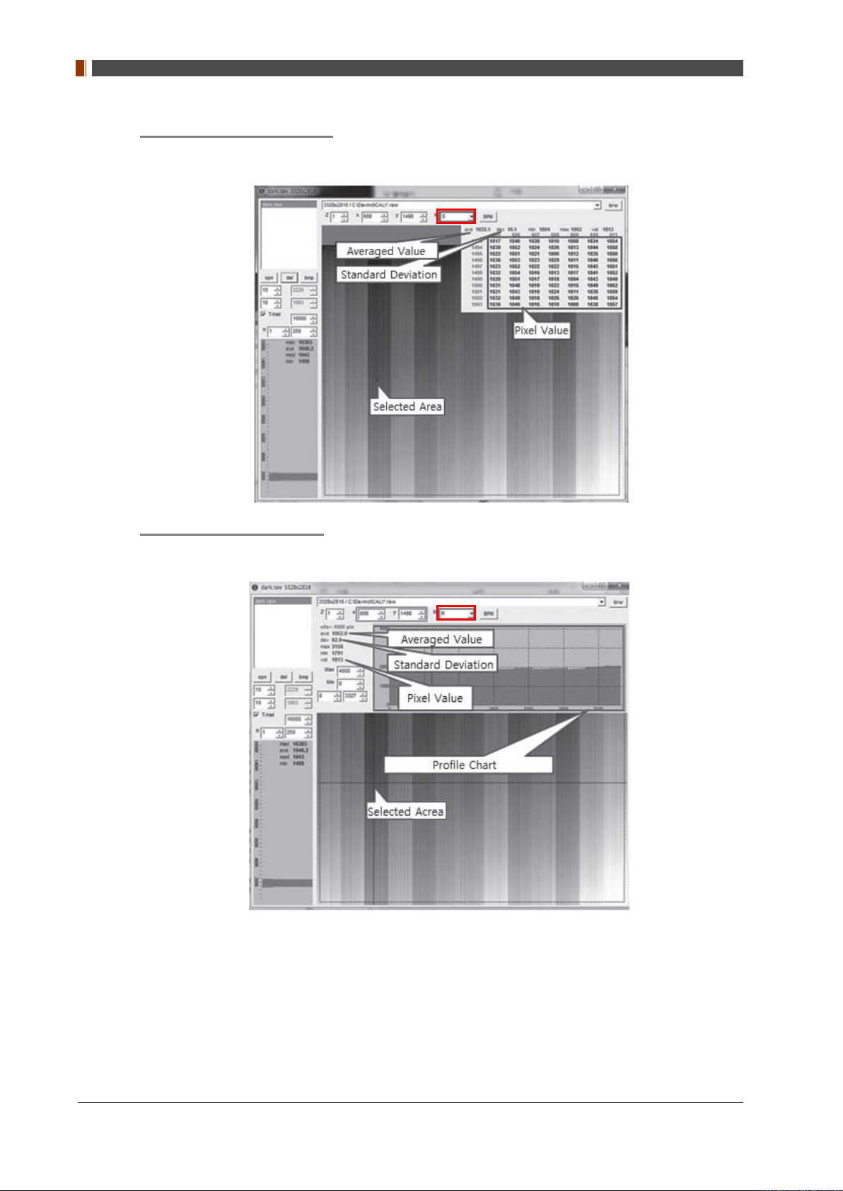
Pixel value at certain level
Choose "S" from marked box.
Profile for horizontal line
Choose "R" from marked box.
104 1417WGC/WCC
PART I. User & Installation Manual
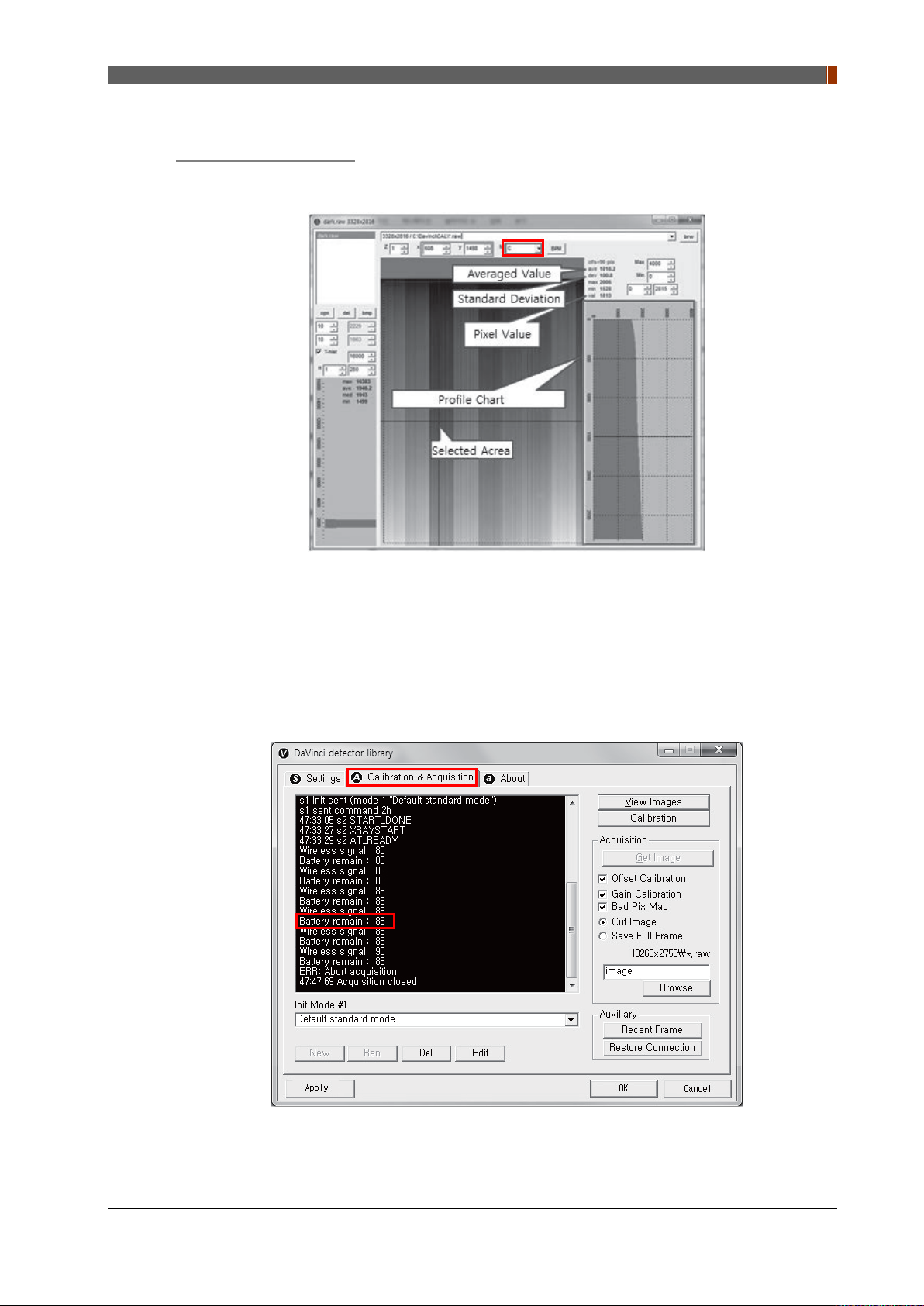
Profile for vertical line
Choose "C" from the marked box.
4.4 Additional Function
4.4.1 Battery Remain
Once you click "Get Image" under the "Calibration & Acquisition” tab, the Status window will
show how much battery remains.
1417WGC/WCC 105
PART I. User & Installation Manual
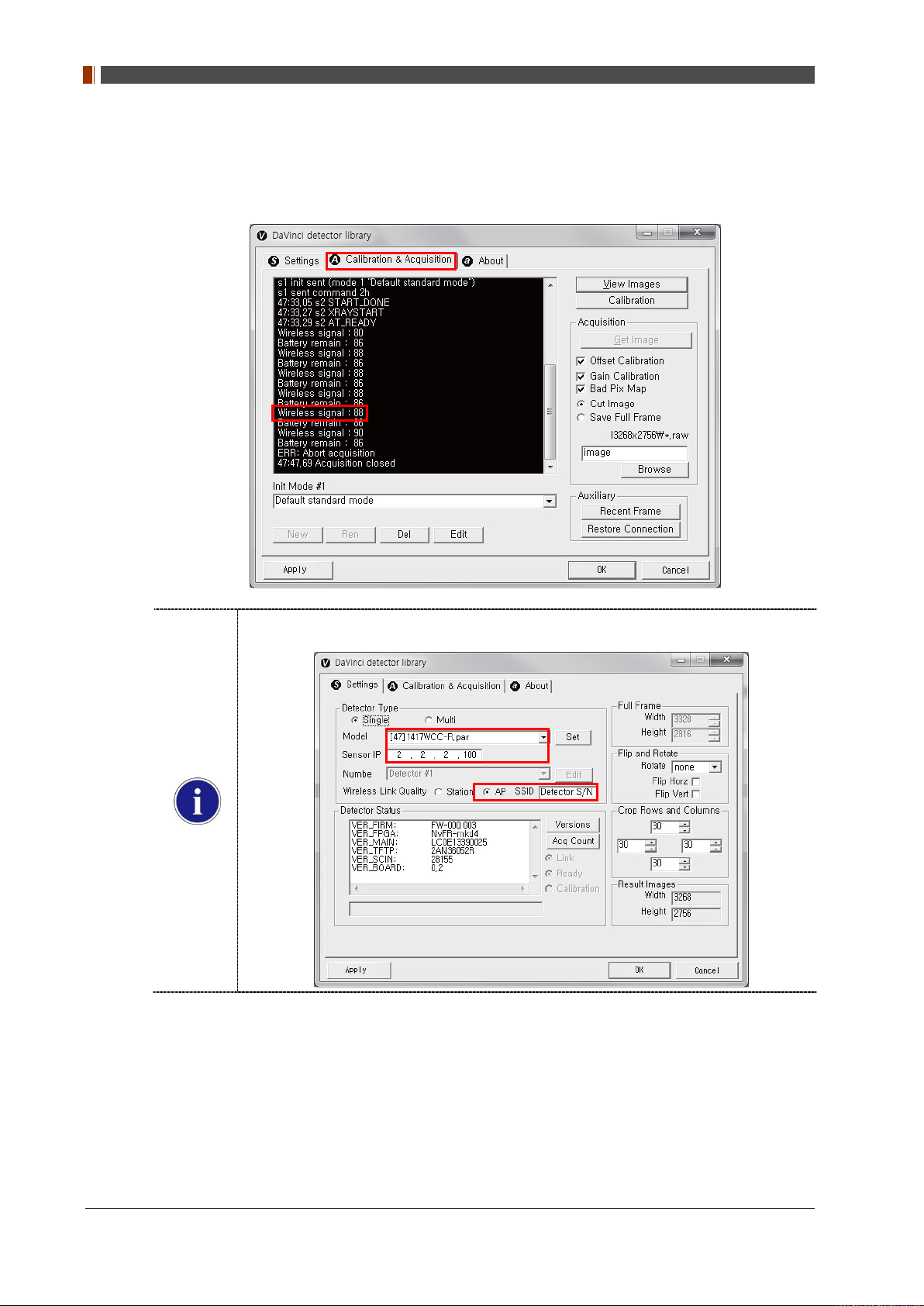
4.4.2 Wireless signal Strength
Once you click "Get Image" under the "Calibration & Acquisition” tab, the Status window will
show the strength of the wireless signal.
Before you check the wireless signal in the AP mode, the detector's serial number should
be entered at the "SSID".
106 1417WGC/WCC
4.4.3 Sleep Mode
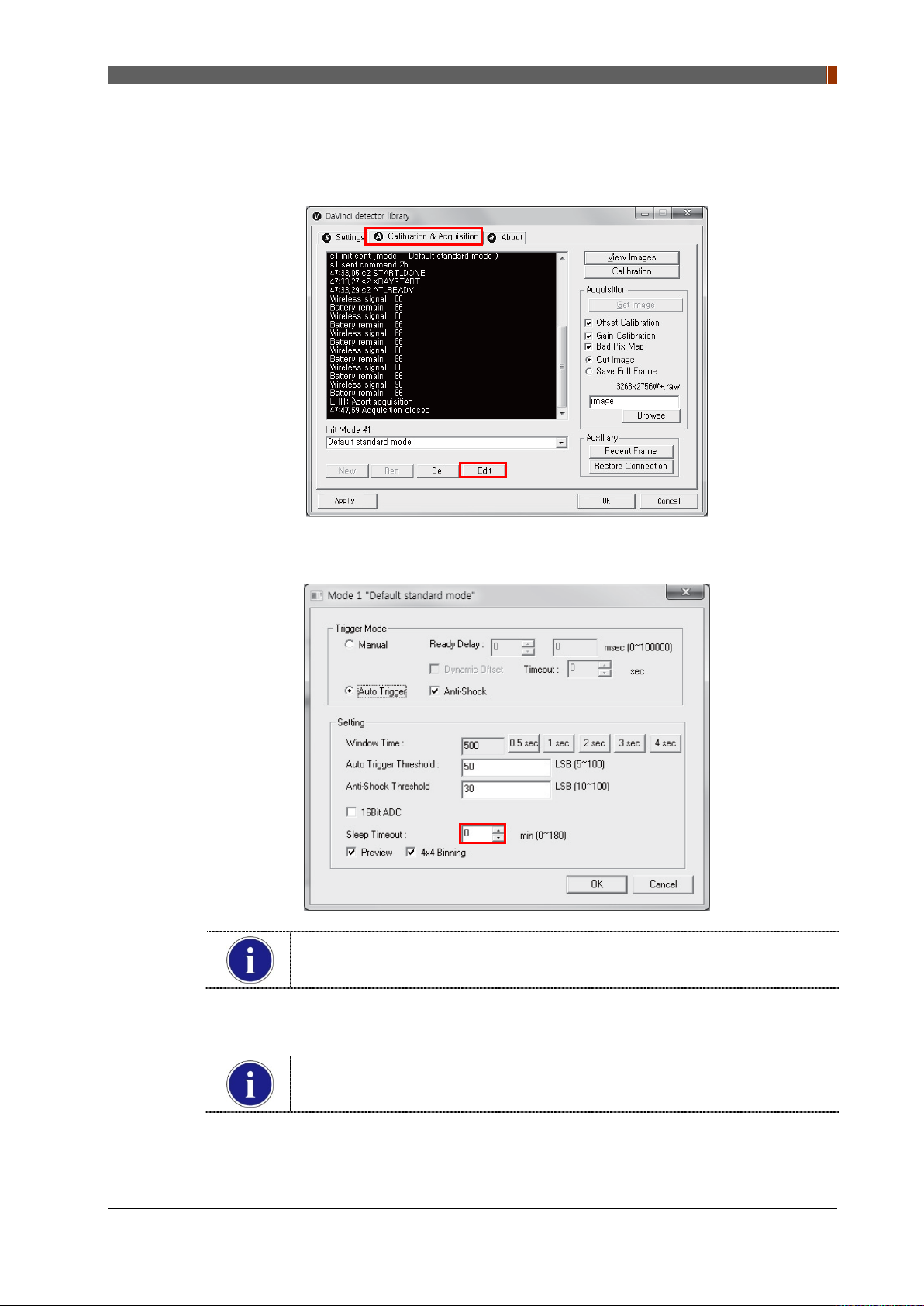
1. Click “Edit” under the Calibration & Acquisition tab.
PART I. User & Installation Manual
2. Under the “Sleep Timeout” setting, enter a designated time for the detector to go into Sleep
Mode.
Sleep Mode does not apply when set to zero.
Power consumption is reduced by 40% when Sleep Mode is used.
3. To turn off Sleep Mode, attempt to acquire an image or press the power button on the
detector just once.
A normal image can be acquired after 10 seconds Sleep Mode has been turned
off.
1417WGC/WCC 107
PART I. User & Installation Manual
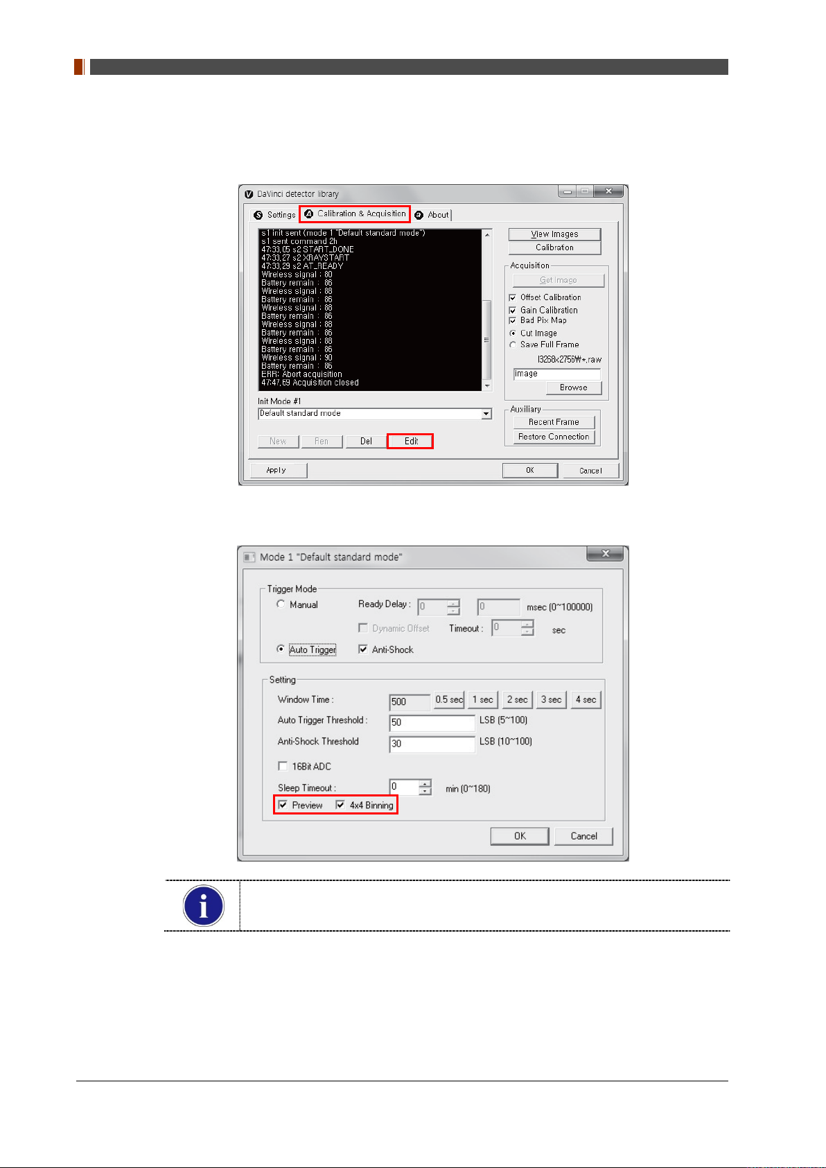
4.4.4 Preview
1. Click “Edit” under the Calibration & Acquisition tab.
2. After checking the Preview and 4x4 Binning, a 4x4 binned image appears which allows for
a quicker image preview.
By unchecking 4x4 Binning, a normal image preview appears.
By unchecking Preview, a full frame image appears.
108 1417WGC/WCC
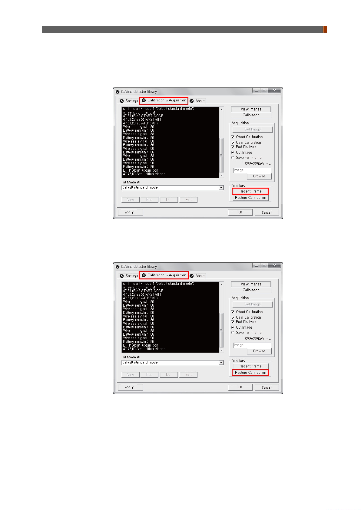
4.4.5 Recent Frame
The last acquired image can be opened by clicking "Recent Frame" under the "Calibration &
Acquisition” tab.
PART I. User & Installation Manual
4.4.6 Restore Connection
When the connection between the detector and PC is lost, the connection can be made again
by clicking "Restore Connection" under the "Calibration & Acquisition” tab.
1417WGC/WCC 109
PART I. User & Installation Manual
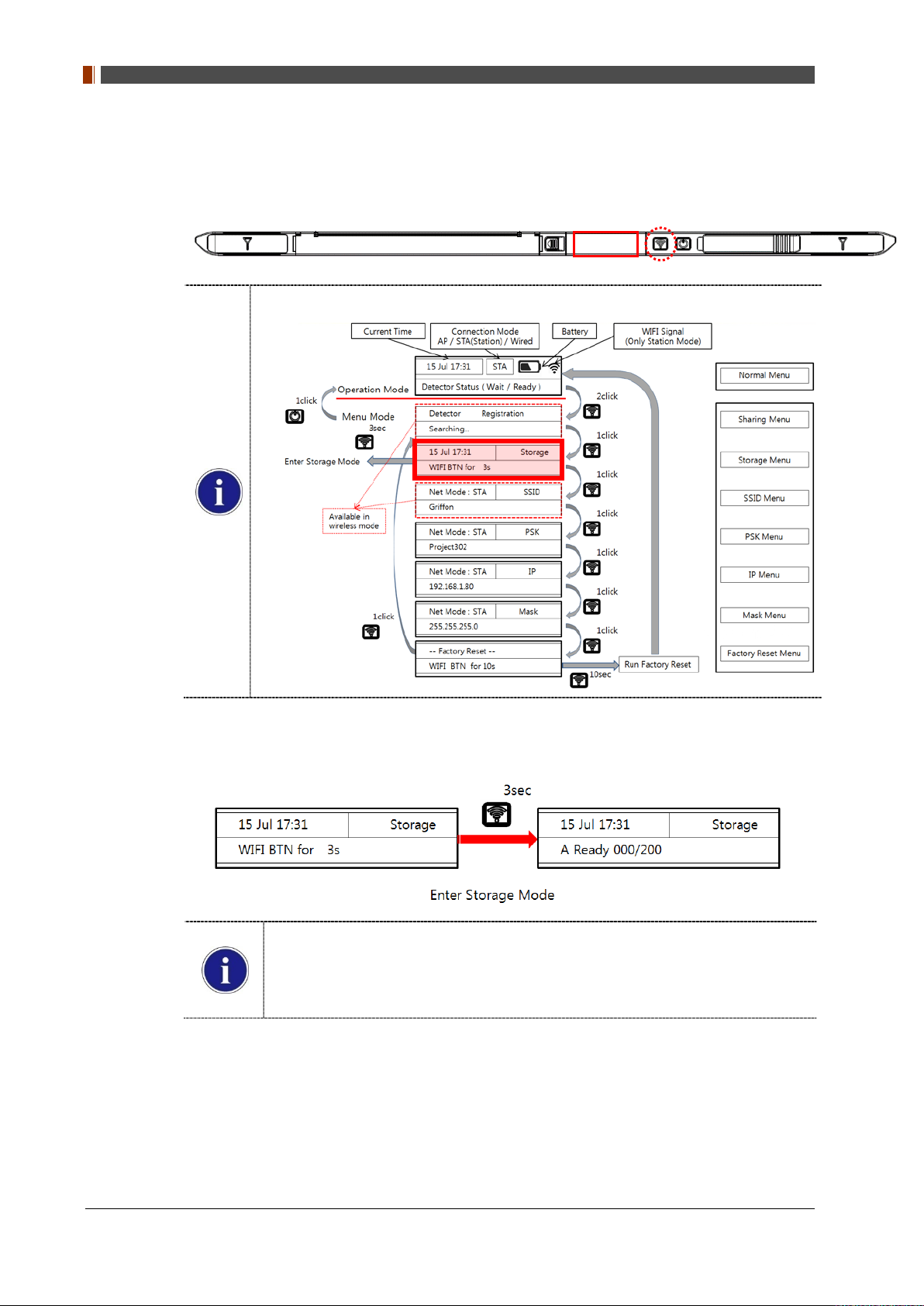
4.4.7 Image Storage function
1. Press the "Mode select button" twice (within 2 seconds) and click one more time to go to
"storage mode".
Mode status can be checked by the OLED window of Detector
2. Press the mode select button for 3 seconds to check the status of storaged images.
When Storage mode is used if the connection between the detector and PC, the
image is stored the memory in the Detector internal
Stored Image can be opened by referring SDK
Image can be stored up to max 200
110 1417WGC/WCC
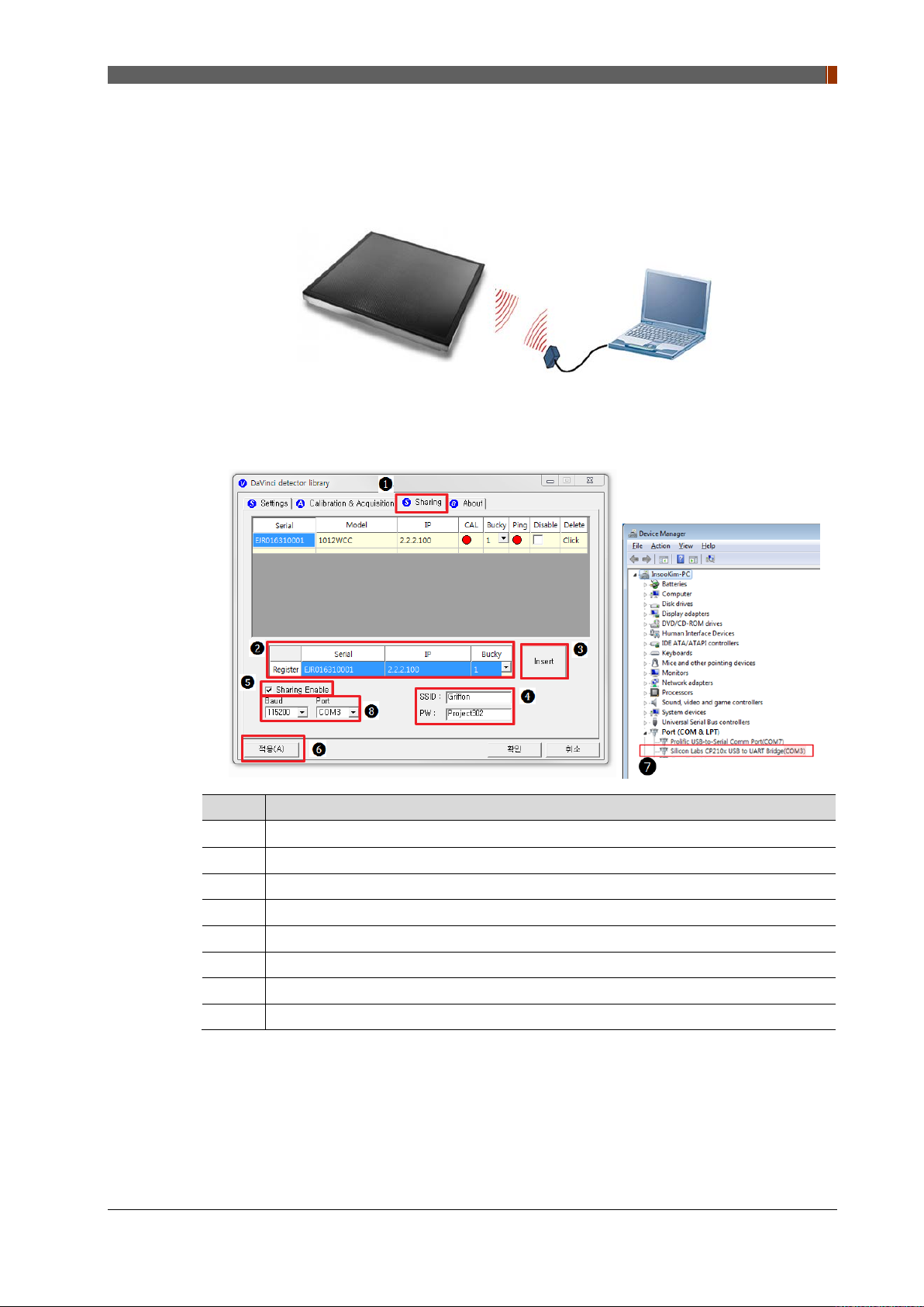
❶
❷
❸
❹
❺
❻.
❼
❽
4.4.8 Sharing function
1. Connect the PC and USB IrDA Dongle by using the Micro USB cable.
2. Set vadavas below
PART I. User & Installation Manual
No. Overview
Click “sharing” tab
Enter follow thing in order “ serial number, IP, bucky number”
Click “insert”
.
Put the SSID and PW of AP
.
Check “Enable check box ”
Click “apply” to save
Confirm the connection port in device manager of OS
Baud select 115200 and select confirmed port in device manager
1417WGC/WCC 111
 Loading...