

Page 1
76LJ
TTC-1
TraceTek Sensing Module Installation, Operation
and Maintenance Instructions
DESCRIPTION
The nVent RAYCHEM TraceTek TTC-1 sensing module is used with
TraceTek sensing cables to detect liquid leaks. The module provides
visual indication when a leak or cable break has occurred and has
TRACETEK
relay contacts to connect the TTC-1 to external devices for remote
monitoring and control.
ELECTRICAL CODES
Installation must be done in accordance with national and local
codes and regulations that apply. The TTC-1 must be installed in
ordinary areas only.
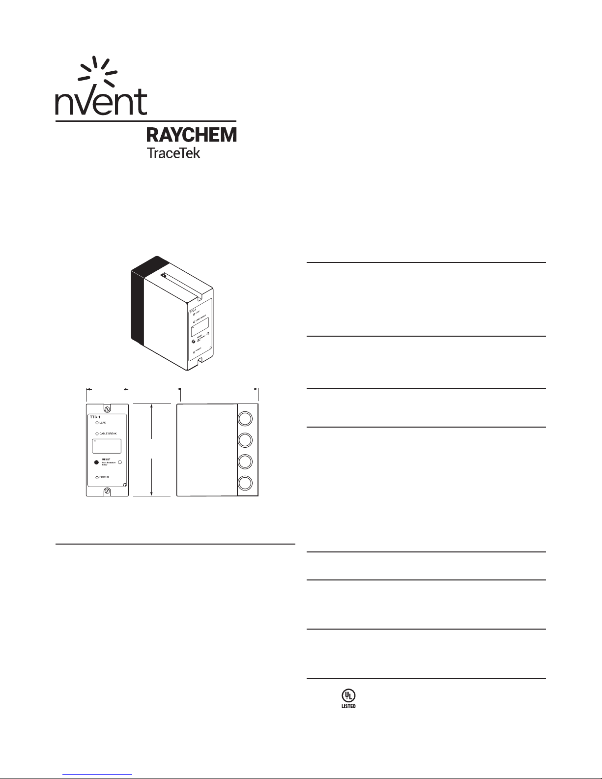
2 in
(52 mm)
TRACETEK
4.4 in
(112 mm)
Figure 1: TTC-1 Module
4.2 in
(106 mm)
IMPORTANT NOTES
• The TTC-1 module is designed for use with TraceTek sensing
cables and probes only. A TTC-1 based system will detect and
alarm on all fluid leaks detected by the TraceTek cable as per
the appropriate cable data sheet.
• Transient spills and contamination may also activate the
system. Users should consider this operational function when
determining the suitability of the TraceTek system for specific
applications.
• The system has not been designed for repetitive cycling.
• Always connect the Leak Detection relay to an annunciation
device (for example the nVent RAYCHEM TraceTek TTE-XAL
External Loud Alarm) so that an operator is notified and can
verify proper operation if automatic equipment is connected.
• Maintenance personnel should examine the sensing cable for
cleanliness and verify proper operation of the TTC-1 module at
least every six (6) months.
MODULE LOCATION
Enclosure rating: IP 20 / NEMA 1
Operating temperature range: 0ºC to 50ºC (32ºF to 122ºF)
SPECIFICATIONS
Maximum sensing cable length: 250 ft (76 m)
• Leader cable length is not included in the length limitation.
Input power:
• 12 to 24 Volts AC – 0.25 A
• 15 to 24 Volts DC – 0.15 A
• When using a transformer, use UL listed Class II transformer
rated at 24 V, 20 VA
Recommended fuse rating: 3 A
Relay ratings: 3 A: 30 Volts DC or 24 Volts AC
INSTALLATION MATERIALS AND TOOLS REQUIRED
Wall fastener (2 ea for surface mounting only)
PARTS AND MATERIALS
• 1 ea TTC-1 Sensing Module
• 1 ea TTC-1 Wall Label
• 4 ea Strain Reliefs
OPTIONAL ACCESSORIES
• TTC-DRC DIN Rail Clip – Part # 062825-000
• TTE-XAL External Loud Alarm – Part # 418569-000
• TT-MAP-TOOL – Part # E43135-000
APPROVALS
TYPE NM
General Signaling Equipment
Page 2
Mounting
16 17 18 19
TTC-1
TTC-DRC
Installing the TTC-1
Preparation for Mounting
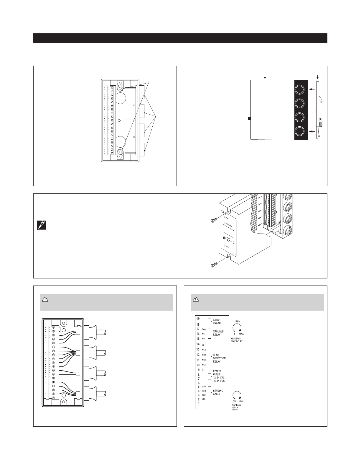
Open the knockouts as required on the base unit. The holes are sized for the PG-9 threaded strain relief provided in the kit.
For Wall Mounting
Use the two holes in the
back plate to mount the
TTC-1 base unit to the
holes 85mm
(center to
center)
wall using suitable wall
fasteners. The mounting
holes are 4mm diameter,
separated by 85mm (center
Cable entry
knockouts
to center). The mounting
screw holes are recessed
into a molded well that
is 7 mm in diameter. It is
recommended to use a J15
metric screw with a head
diameter small enough to
fit into the molded well.
Figure 2: Wall mounting
For proper orientation, the
terminal strip must be on the left, as shown in Figure 2.
Loosen the two captive screws at least 10 full turns. You may
hear a click when screw is fully released. Use a gentle rocking
motion to pull the module top away from the base.
Note: If the screws are not fully released the base can
be damaged during this step. The screws are captive
and will be retained with the module when separated from the
base.
For DIN 1 Rail Mounting
Attach the optional rail
mounting clip (TTC-DRC)
to the base unit and clip
base unit on rail. Remove
the top housing from the
TTC-1. Place one of the
hex nuts in the molded
hex cavity in the center
of the DIN rail plate. Align
the DIN rail plate with
the bottom of the TTC-1
base and insert one of
Figure 3: DIN rail mounting
the screws through the
insulating collar and the hole in the center of the base. Turn the
screw to secure the base. Insert the second hex nut into the
remaining molded hex cavity at the end of the hex plate and use
the second screw to secure the plate.
TRACETEK
ID:
1 2 3 4 5 6 7 8 9 10 11 12 13 14 15
WARNING: To avoid electrical shock – all wiring
must be done with the power off.
19181716151413121110987654321
TROUBLE
RELAY
LEAK
DETECTION
RELAY
POWER
INPUT
SENSOR
LEADER
Figure 5: Terminal block wiring
2 | nVent.com
Strip all wire insulation back 3/8
inch. Push leader
cable, power
supply and relay
contact wires
through the strain
reliefs as needed,
see Figure 5.
Figure 4: Module dis-assembly
WARNING: To avoid electrical shock – all wiring
must be done with the power off.
Wires should be connected to
the terminal strip following the
label on the rear cover plate of
the TTC-1, see Figure 6.
Figure 6: Typical terminal block label
Page 3
Power Supply Connection
Note: For proper operation of the TTC-1, use a power
supply whose output is electrically isolated from the
incoming AC line power and ground.
One (and only one) TTC-1 can be connected to the output of
one of the following suitable power supplies:
a) a transformer (except an autotransformer)
b) an isolated AC-to-DC switching or linear supply
(use a UL Listed Class II power supply)
c) an isolated DC-to-DC switching power supply
(use a UL Listed Class II power supply)
d) a 15 to 24 V battery
Do not connect either leg of the power supply output to
neutral or ground.
To ensure that multiple TTC-1 modules are isolated from
ground and from each other, each TTC-1 module requires a
separate isolated power supply.
There is no polarity requirement when using a DC power supply.
Maximum wire size: 14 AWG.
WARNING: To avoid electrical shock – all wiring
must be done with the power off.
Final Reassembly
When all wiring connections are complete and the field
adjustments have been made, carefully insert the edge of the
circuit board into the terminal strip edge card connector. Using
a gentle rocking motion, push the circuit board module into the
base unit until it seats.
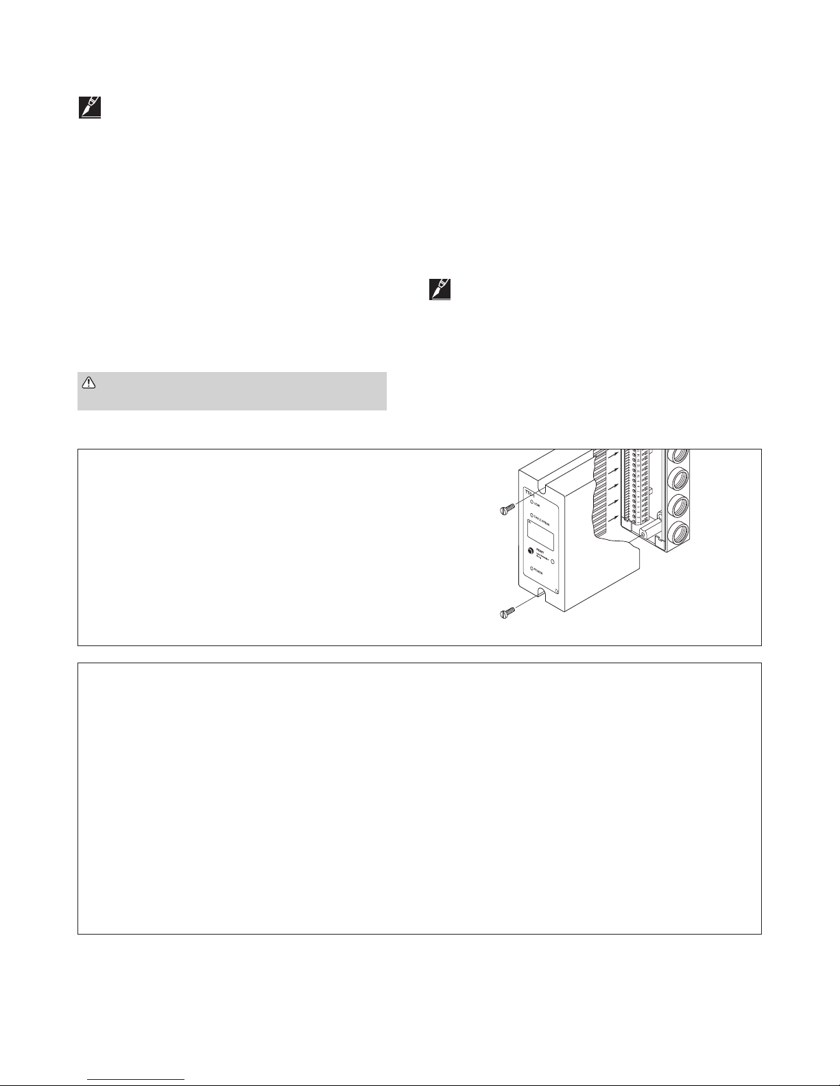
Use the two captive screws on the module to secure the circuit
module to the base, see Figure 7.
Attach the wall label in a conspicuous place near the TTC-1.
Relay Connections
Trouble Relay:
One relay with single pole, double throw contact.
The relay is normally energized. Loss of power at the TTC-1 module
causes the relay to switch to the ALARM condition (COM-NC open).
Leak Detection Relay:
One relay with double pole, double throw contacts.
Leak detection relay latch can be disabled by removing jumper
wire between terminal 18 to 19.
See further discussion in the Field Adjustments and Maintenance
section on page 5.
Note: If relays are connected to automatic equipment,
verify proper operation.
Module Field Adjustments:
Time Delay can be increased from immediate to approximately 2
minutes using adjustment screw on rear panel.
Sensitivity can be increased or decreased from factory setting with
adjustment screw on rear panel.
See further discussions in the Field Adjustments and Maintenance
section on page 5.
TRACETEK
Figure 7: Module reassembly
Final Check List
1. Complete a system inspection in the presence of the owner.
2. Ensure a plan showing the location of the sensor is available.
3. Check that the following information is clearly visible adjacent to the alarm module:
• “In case of alarm” instructions
• Location of the system map in case it is not installed adjacent to the alarm module
• Name and contact number of the person responsible for operating the system
• Supplier’s contact name and address
4. Give these Installation, Operating and Maintenance Instructions to the owner.
5. Make the owner aware that it is strongly recommended to perform a systems check at regular intervals, at least every six (6) months.
nVent.com | 3
Page 4
Operating Instructions
System Operation
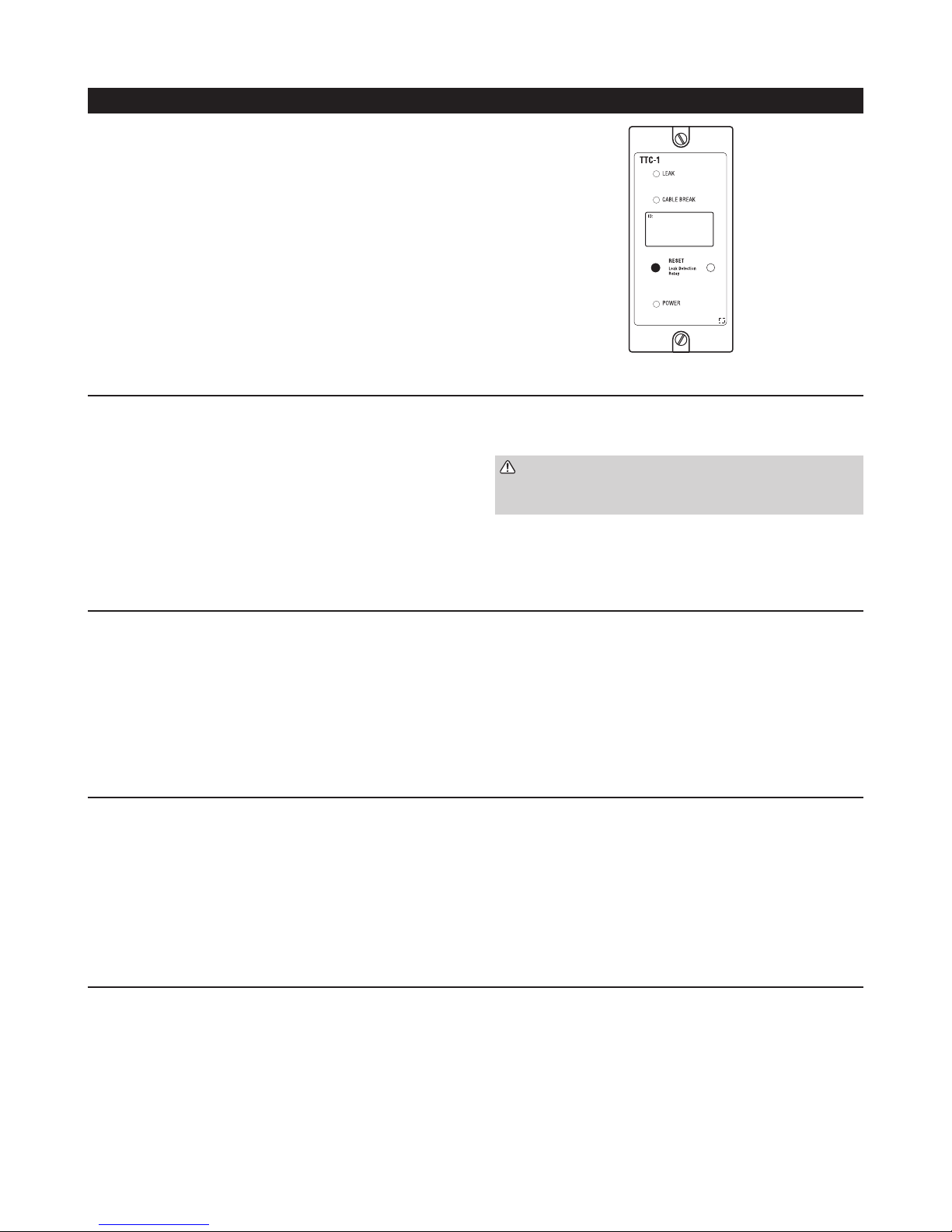
The TTC-1 module and attached sensor cable continuously monitors
for liquid contact and wire breakage. LEDs on the cover of the
enclosure indicate the status of the system, see Figure 8. Relay
contacts react to leak detection as well as trouble conditions:
Normal Mode Indications:
LEAK LED OFF
CABLE BREAK LED OFF
RESET LED OFF
POWER LED ON (green)
TRACETEK
LEAK DETECTION RELAY NORMAL (de-energized)
TROUBLE RELAY NORMAL (energized)
Leak Detection Indication:
LEAK LED ON (red)
CABLE BREAK LED OFF
RESET LED ON (red) (See Note 1)
POWER LED ON (green)
LEAK DETECTION RELAY ALARM (energized)
TROUBLE RELAY NORMAL (energized)
Cable Break Indication:
LEAK LED OFF
CABLE BREAK LED ON (yellow)
RESET LED OFF
POWER LED ON (green)
LEAK DETECTION RELAY NORMAL (de-energized)
TROUBLE RELAY ALARM (de-energized)
Figure 8: TTC-1 front panel
User Action:
1. Press RESET to return Leak Detection relay to NORMAL position
CAUTION: Any equipment that has been automatically
shut down by the Leak Detection relay may be
re-activated when RESET is pushed.
2. Locate the spill area, investigate the cause of the spill and take
the necessary repair actions.
3. Clean up the spill area and clean and dry the cable if necessary.
LEAK LED will turn off when cable is dried.
User Action:
1. Investigate the sensor cable and leader cable for physical
damage. Check connectors for damage. Make repairs or
replace components as necessary.
2. CABLE BREAK LED automatically turns off when full sensor
cable continuity is restored.
3. TROUBLE relay automatically returns to the NORMAL position
when cable continuity is restored.
Power Failure Indication:
LEAK LED OFF
CABLE BREAK LED OFF
RESET LED OFF
POWER LED OFF
LEAK DETECTION RELAY NORMAL (de-energized)
TROUBLE RELAY ALARM (de-energized)
Note 1: The RESET LED is turned on when a leak is first detected. Pushing the RESET button will cause the Leak Detection relay to return to
the NORMAL condition and the red LED to turn off. RESET will work regardless of whether the cable is wet or dry.
4 | nVent.com
User Action:
1. Investigate power wiring and connections, circuit breakers, etc.
to determine cause of power loss. Make repairs as necessary to
restore power to the TTC-1.
2. POWER LED turns on automatically when power is restored.
3. TROUBLE relay returns to NORMAL position when power is
restored.
Page 5
Field Adjustments and Maintenance
Time Delay Adjustment
The leak alarm relay can be adjusted for time delay range up to
2 minutes. The purpose of the time delay is to prevent the alarm
relay from activating on short term transient conditions caused
by air conditioner start-up. The factory default setting is zero
delay.
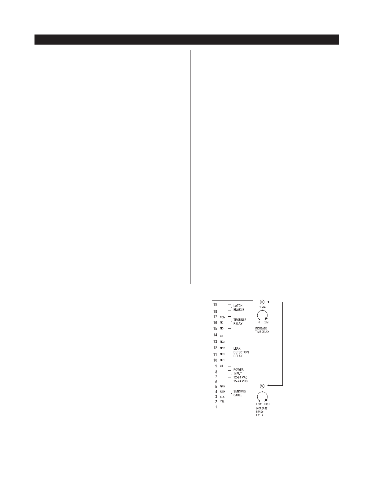
The adjustment screw is accessed through the rear cover
plate when the TTC-1 top cover is removed from the base unit.
(See Figure 9). Rotate the time delay adjustment screw in the
clockwise direction to increase time delay.
Sensitivity Adjustment
The sensitivity adjustment refers to the size of the liquid leak
which will trigger a response from the TTC-1 module. For water
detection applications the factory default setting will cause the
TTC-1 to respond to a puddle of tap water approximately 8 cm
(3 inches) in diameter.
The sensitivity adjustment screw is accessed through the rear
cover plate when the TTC-1 top cover is removed from the base
unit. See Figure 9. Note initial setting before changing.
Sensitivity can be increased by rotating the adjustment screw in
the clockwise direction and decreased by rotating the screw in
the counter clockwise direction. The sensitivity control has very
little effect on TT5000 or TT5001 sensors since these cables
act like ON/OFF switches.
Leak Detection Relay Latch Function
The TTC-1 default setting causes the Leak Detection relay to
latch in the ALARM condition when a leak is first detected.
Resetting the relay to the NORMAL condition is a manual
operation that occurs when the user pushes the RESET
push-button.
In some installations it may be desirable to have the Leak
Detection relay track the sensor cable conditions. (i.e. RELAY in
ALARM mode if the cable is wet and RELAY automatically reset
when the cable dries). This alternative configuration causes the
Leak Detection relay to track the cable condition and no user
interaction is required to reset the leak relay.
To enable automatic relay tracking (and defeat the latch
function), remove the small jumper wire between terminal 18
and 19. See Figure 9.
Periodic Maintenance and Test
Recommended Interval: Perform a functional check per the
following procedures at 6 month intervals. Repair or replace all
damaged wiring and sensor cables. There are no field repair
procedures for the TTC-1 module. If the module fails to perform
the functional tests, it must be replaced.
Test Procedure:
1. Normal Operation: Look for Green POWER LED
2. Leak Simulation: For systems using nVent RAYCHEM
TraceTek TT1000 or TT3000 sensor cable, use a TraceTek
Mapping Tool or a small container of water to simulate
a leak. After the time delay has expired (maximum
2.5minutes) look for the following indications:
• Red LEAK LED on
• Red RESET LED
• Green POWER LED on
• Leak Detection Relay in ALARM condition (Note: This may
cause equipment shut down if devices are connected to
the ALARM relay contacts) (C1-NC1 open, C2-NC2 open)
After above conditions are observed:
• Press RESET
• Red RESET LED turns off
• LEAK RELAY returns to NORMAL condition.
Remove simulated leak:
• Red LEAK LED goes out
For TT5000 and TT5001 systems, simulate a leak condition
by tightly bending and holding the sensor cable.
3. Cable Break Simulation: For any sensor system,
disconnect any sensor connector in the system. Look for
the following indications:
• Yellow CABLE BREAK LED on
• TROUBLE RELAY in ALARM condition (COM-NC open)
Restoring the connection should cause the TTC-1 to return to
the normal indications.
Adjustment
screw
locations
Figure 9: Location of adjustment controls
nVent.com | 5
Page 6

Troubleshooting Guide
Problem: Leak Alarm, but no leak found.
Possible Cause: Cable is dirty (TT1000, TT3000)
Action: Clean cable using water. Dry the cable and check TTC-1
front panel. Heavily contaminated cable may require replacement.
Sensitivity can be adjusted to a lower level, but if dirt is accumulating,
cleaning and/or replacement will eventually be required regardless of
sensitivity setting.
Problem: Leak Alarm, but no leak is found.
Possible Cause: Cable is exposed to occasional water (TT1000,
TT3000)
Action: Increase time delay and/or reposition cable further from the
intermittent source of water. It is best to keep the sensor cable at
least 3 feet from the outflow of any air conditioner units.
Problem: Leak Alarm, but no leak is found.
Possible Cause: Cable is in contact with sharp metal edges
(TT1000, TT3000)
Action: Check the sensor cable for possible points of contact with
sharp edges such as the edges of drip pans or the pipe threads on
adjustable floor supports. Reposition the cable as necessary or insert
a small piece of insulating material to prevent the cable from making
contact with the metal edge.
Problem: Leak Alarm, but no leak is found.
Possible Cause: Cable is pinched (all cables)
Action: Check the sensor cable for possible pinch points. nVent
RAYCHEM TraceTek TT5000 and TT5001 can be tripped if tightly
bent or compressed by a heavy object. TT1000 and TT3000 can be
tripped by heavy pressure from a metallic object. Check the entire
cable installation for pinch points and correct the condition.
Problem: CABLE BREAK indication but cable appears to be intact.
Possible Cause: Loose connections at terminal block.
Action: Check all terminal block screws for tightness. To test the
module by itself, use two small pieces of wire to form temporary
jumpers from red to green and yellow to black at the sensor cable
terminal block. This simulates a very short piece of sensor cable
and the yellow CABLE BREAK LED should go off. If the TTC-1 cannot
pass the jumper wire test, it may require replacement.
Problem: PLC or other host system detects a fault when the
TTC-1 is operating in NORMAL mode.
Possible Cause: Loose connections at terminal block or broken
wires between TTC-1 and PLC.
Action: Check all terminal block screws for tightness. Many
installations use a normally closed contact to indicate a normal
condition at the TTC-1. If the wiring between the TTC-1 and the PLC
is loose or open, then the host system will read the open circuit as a
fault regardless of the TTC-1 status.
Note: Cable Cleaning
TraceTek 1000 and TT3000 use a solid core polymer construction and can usually be easily cleaned with tap water. In extreme
cases or when large amounts of cable are contaminated, these cables can be washed in an ordinary dishwasher. Try a water
only (no detergent) cycle first and avoid the heated dry cycle. When placing the cable in the dishwasher be sure to tightly
connect the male connector on one end to the female connector on the other in order to keep water out of the connectors.
TT5000 and TT5001 cannot be cleaned without special equipment. These cables normally require replacement after
exposure to fuel or solvent.
North America
Tel +1.800.545.6258
Fax +1.800.527.5703
[email protected]
Europe, Middle East, Africa
Tel +32.16.213.511
Fax +32.16.213.604
[email protected]
Asia Pacific
Tel +86.21.2412.1688
Fax +86.21.5426.3167
[email protected]
Latin America
Tel +1.713.868.4800
Fax +1.713.868.2333
[email protected]
nVent.com
©2018 nVent. All nVent marks and logos are owned or licensed by nVent Services GmbH or its aliates. All other trademarks are the property of their respective owners.
nVent reserves the right to change specications without notice.
RaychemTraceTek-IM-H53813-TTC1-EN-1805
 Loading...