

Page 1

RMM2-E
TRACE-HEATING REMOTE MONITORING MODULE
EXTERNES BEHEIZUNGS-ÜBERWACHUNGSMODUL
MODULE DE SURVEILLANCE À DISTANCE POUR TRAÇAGE ÉLECTRIQUE
МОДУЛЬ ДИСТАНЦИОННОГО КОНТРОЛЯ ЭЛЕКТРООБОГРЕВА
Page 2

C | nVent.com
INSTALLATION INSTRUCTIONS
Description
The nVent RAYCHEM Remote Monitoring
Module (RMM2-E) is part of the RAYCHEM NGC
control and monitoring system. The RMM2-E
accepts inputs from up to 8 RTDs (3 wire Pt 100
temperature sensors) measuring pipe or ambient
temperature in a trace heating system.
Up to 16 RMM2-E units communicate with a
RAYCHEM NGC-30 or NGC-40 controller using
a single RS-485 cable.
For technical assistance, call your local nVent
representative or the nVent service center listed
on the last page.
Parts (supplied)
RMM2-E without enclosure
• RMM2-E Trace-heating Remote Monitoring
Module
• Replacement fuses
• Jumper for voltage selection
• Label
Hazardous Area Unit (RMM2-EX-E)
• RMM2-EX-E Trace-heating Remote
Monitoring Module
• Exn R II T6 glassfibre-reinforced polyester
enclosure
• 12 Ex e M20 glands for power cable
(6 to 12 mm cable diameter) with mushroom
stopping plugs
• Replacement fuses
• Jumper for voltage selection
WARNING:
This component is an electrical device. It must be
installed correctly to ensure proper operation and
to prevent frozen pipes, shock or fire. Read and
carefully follow all the installation instructions.
Approvals
RMM2-EX-E:
Hazardous Areas
II 3 G/D T=70°C EExn R II T6
(Ta –20°C to +60°C)
Baseefa03ATEX0739
TC RU C-BE.ИМ43.B.01764
2Ex nR II T6 Gc IP66
Ta -55°C…+60°C
ООО “ТехИмпорт”
Special conditions for safe use:
All unused entry holes must be sealed using the
scheduled cable gland and stopping plug.
Consider the effects of direct heating on the
exterior of the enclosure and the impact this may
have on the internal temperature rise.
Non-Hazardous Areas
RTD and RS-485 circuitry
are isolated from power
mains circuitry by protective
separation.
Tools Required
• 7 mm flat-blade screwdriver
• 3 mm flat-blade screwdriver
• wire stripper/cutter
• 27 mm spanner (for M20 glands)
Page 3

nVent.com | 3
Specifications
Supply voltage (nominal): 115/230 Vac, ±10%, jumper selectable, 50/60 Hz
Power consumption: 2,5 VA
Ambient operating range: –40°C to +60°C
–20°C to +60°C (Exn enclosure and glands)
Relative humidity: 5 to 95%, noncondensing
Temperature sensors: 3-wire RTD (Pt 100)
Temperature coefficient: per IEC 751-1983 (100 Ω at 0°C)
Sensor connections: Can be extended with a 3-core shielded cable of 20 Ω max. per
conductor (e.g., 150 m with 3 x 1.5 mm2 cable)
RS-485 connections: Shielded, single twisted pair, max. 1200 m
Replaceable fuse: F 200 mA/250 V, Wickmann part number 19370-034-K (FAST BLOW)
Installation materials (not supplied)
Fasteners
4 screws for 6.5 mm holes for mounting enclosures
Pt 100 temperature sensors (RTDs)
MONI-PT100-NH Temperature sensor for non-hazardous areas with M20 cable gland
MONI-PT100-EXE Temperature sensor for hazardous areas
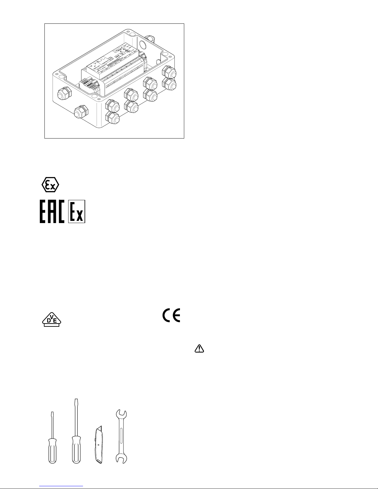
Remote Monitoring Module (RMM2-E)
1
Fuse (200 mA, 250V)
2
Terminals for power input with provision for
daisy chaining
3
Voltage selector jumpers
4
Terminals for RS-485 bus
5
LEDs which indicate communications
activity
6
LED which indicates power to the
RMM2-Eunit
7
Rotary switch (16 position) to assign
RS-485address
8
Terminals for RTD lead wires
9
Shorting block to select RS-485
terminationmode
60 mm
42 mm
15
mm
75
mm
125 mm
0
Install per nVent RMM2 Instructions Manual nVent Montage- und
Betriebsanleitung beachten Suivre attentivement les intructions
d’installation de nVent
60 mm
42 mm
15
mm
1
2
3 4
5
6
7
8
9
Page 4

C | nVent.com
Overview of Installation Procedure for the RMM2-EX-E
A. Mount RMM2-EX-E enclosure and install cables.
B. Connect power and earth wiring and select voltage operating range.
C. Connect RTD cables to the RMM2-EX-E.
D. Select RS-485 address for the RMM2-EX-E and connect the RS-485 bus cables.
Note: Installation to be performed by suitable trained personnel.
Note: Keep the Remote Monitoring Module clean and dry prior to installation to avoid damage to
internal components.
Note: When RMM2-E is used for DIN-rail installation in a local customised panel or enclosure,
must be added 10 earth terminals for earthing of RTD’s and power cables. Terminals should
accept wires from 0.2 to 4 mm
2
.
A. Mount Enclosure and Install Cables
1. Select a suitable location for the
RMM2-EX-E enclosure.
The enclosure is suitable for use in Zone 2 areas.
Do not mount in Zone 1 or Zone 0 areas. For
installations in Zone 1 areas, contact nVent.
Use the dimensions to locate mounting holes
for the enclosure. Mount the enclosure using
suitable screws (hole diameter 6 mm).
2. Install cables
Install power cable(s), RS-485 cable(s) and RTD
cables into enclosure using glands supplied.
Keep stopping plugs in unused entries.
0
91
160
110
260
240
6.5
Page 5

nVent.com | 5
B. Connect Power and Earth Wiring and
Select Voltage Operating Range
3. Select the voltage operating range
Connect the supplied wire jumpers to the
appropriate terminals to select input voltage.
The RMM2-E is supplied jumpered for 230 volts.
4. Connect wiring from power source to
designated terminals on RMM2-E.
Use only copper conductors. Connect power
cable wires to the terminals marked L1 and L2 on
the RMM2-E. If power is being daisy chained, be
sure to maintain polarity of L1 and L2 wiring for
incoming and outgoing wires.
The terminals accept stranded wires from
0.2 – 2,5 mm
2
. (0,2 - 4 mm2 solid wire)
5. Connect earth wiring.
Connect the earth wire(s) to the earth terminals
mounted on the DIN rail. The terminals accept 0,8
- 2,5 mm
2
solid or stranded wires.
Jumpered
for 115V
Jumpered
for 230V
0
2
0
3
Page 6

C | nVent.com
C. Connect RTD Cables to the RMM2-E
The RMM2-E has terminals for 8 three-wire, RTDs
(Pt 100 temperature sensors, to IEC 751); do not
use other types of RTDs. Select RTDs appropriate
for the usage:
MONI-PT100-NH Temperature sensor for
non-hazardous areas
MONI-PT100-EXE Temperature sensor for
hazardous areas
Install each RTD in accordance with the
installation instructions shipped with it, and run
the RTD lead wires to the RMM2-E.
Note: Resistance of lead wires from each RTD
must not exceed 20 Ω (e.g. 150 m with
3 x 1,5 mm
2
cable).
0
8
RMM2-E
terminal no.
1
2
3
4
5
6
7
8
Piping drawing
identification
Description or location
6. Connect lead wires from each RTD to the
selected RMM2-E terminal block
The RMM2-E has 8 terminal blocks to connect
lead wires from 8 RTDs. Each RTD connection
is numbered; the number identifies the RTD, and
determines the order in which the RAYCHEM
NGC system displays the RTD measurement.
Therefore, order the RTD connections in a manner
that makes the RAYCHEM NGC system display
most meaningful.
The RMM2-E cover shows the correct wiring
arrangement for the RTD wires. With RAYCHEM
RTDs, connect the two RTD lead wires of the
same colour to the terminals marked “-“ and
connect the RTD lead wire that is a different
colour to the + terminal.
7. If RTD-shield is not earthed elsewhere,
connect shield to earth terminal.
8. Record the location/identification for
eachRTD.
Because the RMM2-E terminal connection
number identifies the RTD in the RAYCHEM
NGC system, it is important to record the
location of each RTD. Use the space below to
record the connections, and label the RMM2-E
or its enclosure with this RTD identification
information.
Page 7

nVent.com | 7
D. Select RS-485 Address and Connect the
RS-485 Bus Cables
9. Select the RS-485 address for the
RMM2-Eunit.
Each RMM2-E connected to a RAYCHEM NGC
control and monitoring system must have a
unique address; if two RMM2-E’s are assigned the
same address, communication faults will result.
To ensure that you assign a unique address to
each RMM2-E unit, do the following:
• Review the RAYCHEM NGC system layout; if a
layout document does not exist, create one. If
it has not already been done, assign an RS-485
address to each RMM2-E (up to 16) connected
to the RAYCHEM NGC system.
• If you are adding one or more RMM2-E units to
an existing RAYCHEM NGC network, confirm
that the RS-485 addresses for existing RMM2-E
units correspond to the system layout. See
for details the programming guide of the
RAYCHEM NGC system.
By checking the RS-485 addresses on an existing
system, you can avoid potential conflicts that
would be confusing and time consuming to
troubleshoot otherwise.
Record the RS-485 address selected for the
Remote Monitoring Module you are currently
installing, and label the exterior of the enclosure
with the address assigned to the RMM2-E.
For reference, here are the 16 possible RS-485
addresses: (0 -15 HEXADECIMAL)
0 1 2 3 4 5 6 7
8 9 A B C D E F
10. Set the RS-485 address for the RMM2-E unit
using the rotary switch provided
Take of the lid and use a flat-blade screwdriver to
rotate the RS-485 address switch to the desired
position. The single character visible on the
switch indicates the RS-485 address assigned.
0
7
6
0
11. Connect the RS-485 bus
Note: Do not make connections to the RS-485
bus while it is connected to an operating
RAYCHEM NGC network. Damage and/or alarms
could result.
The RS-485 bus allows units with unique
addresses to be connected together along a
common bus. To add a new unit to the network,
simply connect the RS-485 bus from the last unit
to the new one, or insert the new unit between
two existing units on the bus. The order in which
units are attached to the RS-485 bus does not
matter. There are just two constraints on the
RS-485 network:
• Each RMM2-E must be assigned a unique
address
• The RS-485 bus must be a continuous string
from the first network device to the last
RMM2-E in the system.
Note: The RS-485 bus operates at 5 V, and
equipment connected to it could be damaged by
exposure to higher voltages. Take precautions to
avoid exposing the RS-485 wiring to discharge of
static electricity or other sources of high voltage
potential; in particular, avoid contact with the
power supply wiring.
Page 8

C | nVent.com
The RMM2-E has two sets of terminals for
connections to the RS-485 bus. One terminal
block allows the RMM2-E to connect to the
RS-485 bus, the second allows a continuation of
the bus to other RMM2-E units on the network.
Observe polarity, which is indicated on the
RMM2-E. Connect the incoming RS-485 bus to
the set of terminals marked “IN”, observing the
polarity noted on the cover of the RMM2-E; use
the terminal marked “S” for the shield of the
RS-485 cable. Connect the continuation
of the RS-485 bus to the set of terminals marked
“OUT” in the same manner (not required for the
last RMM2-E in the network).
Important: Do not connect the shield of the
RS-485 cables to the enclosure’s grounding
terminal. Connect the shield only to the RMM2-E
terminals provided. To avoid the potential
for spurious ground loops, the RS-485 cable
shield should be connected to ground only in
the RAYCHEM unit. For the last RMM2-E in the
network, terminate the RS-485 bus by removing
the shorting block on jumper location J17 from
2–3 and placing it across pins 1–2.
OR
NGC-30 via UIT2 NGC-40 via Bridge module
Page 9

nVent.com | 9
Page 10
C | nVent.com
MONTAGEANLEITUNG
Beschreibung
Das nVent RAYCHEM Überwachungsmodul
(RMM2-E) ist Teil des RAYCHEM NGC Steuer-,
Regel- und Überwachungssystems. An ein
RMM2-E können bis zu 8 WiderstandsTemperatursensoren (Pt 100- Sensor in 3-LeiterTechnik) angeschlossen werden, welche die
Temperaturen der beheizten Oberflächen oder
die Umgebungstemperaturen im Heizsystem
erfassen. Das Steuer- und Überwachungsgerät
RAYCHEM NGC-30 oder NGC-40 kann mit bis
zu 16 RMM2-E-Modulen über ein RS-485-Kabel
kommunizieren.
Wenden Sie sich für weitere technische
Unterstützung wenden Sie sich bitte an die für Sie
zuständige nVent-Vertretung.
Lieferumfang
RMM2-E (ohne Zusatzgehäuse, für den NichtEx-Bereich)
• RMM2-E Externes Beheizungs-Überwachungs-
modul
• Ersatzsicherungen
• Brücken (Jumper) für Spannungswahl
• Aufkleber
RMM2-EX-E (mit Zusatzgehäuse, für
Ex-Bereiche)
• RMM2-EX-E Externes Beheizungs-
Überwachungs modul
• EExn R II T6 glasfaserverstärktes
Polyester-Gehäuse
• 12 Stück M20 Kabelverschraubungen in
Eex e-Ausführung mit Blindstopfen
(für Netzkabel, RS-485-Leitung
und Sensorleitungen, 6-12 mm
Leitungsdurchmesser)
• Ersatzsicherungen
• Brücken (Jumper) für Spannungswahl
WARNUNG:
Bei diesem Gerät handelt es sich um eine
elektrische Vorrichtung. Für den einwandfreien
Betrieb und zur Vermeidung gefrorener
Rohrleitungen, elektrischer Schläge oder
Brände muss das Gerät fachgerecht installiert
werden. Lesen Sie alle Installationsanweisungen
sorgfältig durch und befolgen Sie diese.
Zulassungen
RMM2-EX-E:
Ex-Bereiche:
II 3 G/D T=70°C EExn R II T6
(Ta –20°C to +60°C)
Baseefa03ATEX0739
TC RU C-BE.ИМ43.B.01764
2Ex nR II T6 Gc IP66
Ta -55°C…+60°C
ООО “ТехИмпорт”
Besondere Bedingungen für den
sicherenEinsatz:
Alle nicht verwendeten Öffnungen müssen
mithilfe der vorgesehenen Kabelverschraubung
und des Blindstopfens verschlossen werden.
Auch ein potenzieller Temperaturanstieg
im Gehäuseinneren aufgrund direkter
Wärmeeinwirkung auf die Gehäuseaußenseite
muss berücksichtigt werden.
Non-Hazardous Areas
Die Sensor- und RS-485
Stromkreise sind von den
Netzstromkreisen durch
Schutzvorrichtungen getrennt.
Erforderliches Werkzeug
• 3 mm Schlitz-Schraubendreher
• 7 mm Längsschlitz-schraubendreher
• Abisolierzange/Cutter
• 27 mm Maulschlüssel
(für M20 Verschraubungen)
Page 11

nVent.com | 11
Technische Daten
Betriebsspannung: AC 115/230 V, +/- 10%, 50/60 Hz, mit Brücke (Jumper)
wählbar 50/60 Hz
Eigenverbrauch / Nennleistung: 2,5 VA
Einsatztemperaturbereich: –40°C bis +60°C
–20°C bis +60°C (Exn-Gehäuse und Blindstopfen)
Relative Luftfeuchtigkeit: 5 bis 95 %, nicht kondensierend
Temperatursensoren: Pt 100-Temperatursensor in 3-Leiter-Technik
Temperaturkoeffizient: gemäß IEC 751-1983 (100 Ω bei 0°C)
Sensoranschlüsse: Können mit einem 3-adrigen geschirmten Kabel von max.
20 Ω pro Leiter (z.B. 150 m mit einem 3 x 1,5 mm2 -Kabel)
verlängert werden
RS-485-Anschlüsse: Geschirmte, verdrillte 2-Ader-Leitung, max. 1200 m
Ersatzsicherung: F 200 mA/250 V, Wickmann-Ersatzteilnummer
19370-034-K (flink)
Installationsmaterial (im Lieferumfang nicht enthalten)
Halterungen
4 Schrauben für 6,5-mm-Bohrungen zur Gehäusemontage
Pt 100-Temperatursensoren
MONI-PT100-NH Temperatursensor für Nicht-Ex-Bereich mit M20-
Kabelverschraubung
MONI-PT100-EXE Temperaturesensor für Ex-Bereiche (EEx e II T6, Zone1) mit
M20-Kabelverschraubung
Abmessungen (nominal)
1
Sicherung (F 200 mA, AC 250 V)
2
Netzanschlussklemmen mit Möglichkeit für
Daisy-Chaining
3
Brücken (Jumper) zur Netzspannungswahl
4
Anschlussklemmen RS-485-Bus
5
Gelbe LED, Datenübertragung
6
Grüne LED, Netzspannungsanzeige
7
Drehknopfschalter, Adresseneinstellung
16 Positionen
8
Anschlussklemmen für Sensorleitung
(Pt 100 in 3-Leiter-Technik)
9
Brücke (Jumper) RS-485-Netzwerkabschluss
60 mm
42 mm
15
mm
75
mm
125 mm
0
Install per nVent RMM2 Instructions Manual nVent Montage- und
Betriebsanleitung beachten Suivre attentivement les intructions
d’installation de nVent
60 mm
42 mm
15
mm
2
3 4
5
6
7
8
9
Page 12

C | nVent.com
Installationsverfahren RMM2-EX-E
A. Montieren Sie das RMM2-EX-E-Gehäuse, und verlegen Sie die Kabel.
B. Schließen Sie das Netzkabel und den Erdungsleiter an und stellen Sie den
Betriebsspannunsgbereich ein.
C. Schließen Sie die Pt 100-Sensorleitung am RMM2-EX-E an.
D. Legen Sie die RS-485-Adresse für das RMM2-EX-E fest, und schließen Sie die RS-485-Kabel an.
Anmerkung: Die Installation muss von fachgeschultem Personal vorgenommen werden.
Anmerkung: Bewahren Sie das RMM2-EX-E zur Vermeidung von Schäden an der geräteinternen
Elektronik vor der Installation sauber und trocken auf.
Anmerkung: Soll ein RMM2-E auf einer DIN-Schiene im Schaltschrank oder Anschlusskasten installiert
werden, so müssen ggf. zusätzlich 10 Erdungsklemmen (0,2 bis 4 mm
2
) für die Pt-100-
Sensoren und die Netzkabel installiert werden.
A. Gehäusemontage und Kabelinstallation
1. Wählen Sie einen geeigneten Montageort für
RMM2-EX-E-Gehäuse
Das Gehäuse eignet sich für den Betrieb in Zone2-Bereichen. Montieren Sie das Gehäuse nicht in
Bereichen der Zone 1 oder Zone 0. Wenden Sie
sich für Installationen in Bereichen der Zone 1
annVent.
Beziehen Sie sich auf die Abmessungen, um die
Stellen für die Löcher zur Montage des Gehäuse
zu ermitteln. Befestigen Sie das Gehäuse mit
geeigneten Schrauben (Lochdurchmesser 6 mm).
2. Kabelinstallation.
Führen Sie das/die Netzkabel, RS-485Kabel sowie die Sensorkabel über die
Kabelverschraubungen in das Gehäuse ein.
Nehmen Sie die Blindstopfen von den nicht
benötigten Eingängen nicht ab.
0
91
160
110
260
240
6.5
Page 13

nVent.com | 13
Brücken-
anordnung
für 115 V
Brücken-
anordnung
für 230 V
B. Schließen Sie das Netzkabel und den
Erdungsleiter an, und stellen Sie den
Betriebsspannunsgbereich ein
3. Einstellung des Betriebsspannungsbereich
Stecken Sie für die Festlegung der
Eingangsspannung die mitgelieferten
Brücken (Jumper) auf den entsprechenden
Anschlussklemmen auf.
Bei der Auslieferung des RMM2-E sind die
Brücken (Jumper) für AC 230 V angeordnet.
4. Anschließen der Netzleitung
Verwenden Sie ausschließlich Kupferleiter.
Schließen Sie die Leiter des Netzkabels an die
mit L1 und L2 gekennzeichneten Anschlussklemmen an. Achten Sie bei Anwendung des
Daisy Chain Verfahrens auf die Beibehaltung
der „Polarität“ der Verdrahtung L1 und L2 für die
ein- und ausgehenden Leiter.
Die Anschlussklemmen sind für mehrdrähtige
Leiter von 0,2 mm
2
– 2,5 mm2 Leiterquerschnitt
oder eindrähtige Leiter von 0,2 mm
2
– 4 mm2
Leiterquerschnitt geeignet.
5. Anschließen der Erdleiter
Schließen Sie den/die Erdungsdrähte an den auf
der DIN-Schiene angebrachten Erdungsklemmen
an. Die Anschlussklemmen sind für ein- oder
mehrdrähtige Leiter einem Querschnitt von 0,8
mm
2
bis 2,5 mm2 ausgelegt.
0
2
0
3
Page 14

C | nVent.com
C. Anschluss der Pt 100-Sensorleitungen
an das RMM2-E
Am RMM2-E befinden sich Anschlussklemmen
für 8 Pt-100-Temperatursensoren in 3-LeiterTechnik (gem. IEC 751). Verwenden Sie keine
anderen Sensortypen.
Wählen Sie die Pt-100-Sensoren je nach
Einsatzbereich aus:
MONI-PT100-NH Temperatursensor für Nicht-
Ex-Bereiche
MONI-PT100-EXE Temperatursensor für
Ex-Bereiche
Installieren Sie alle Pt-100-Sensoren gemäß der
dazugehörigen Montageanleitung und verlegen
Sie die Pt-100-Sensorleitungen für den Anschluss
an das RMM2-E.
Anmerkung: Der Widerstand der Adern an
allen Pt-100-Sensorleitungen darf 20 Ω nicht
übersteigen (z. B. 150 m mit 3 x 1,5-mm
2
-Kabel).
0
8
RMM2-E Anschluss-terminal
no.
1
2
3
4
5
6
7
8
Piping drawing
kennzeichnung
RohrverlegungsBeschreibung oder Montageort
6. Schließen Sie die Adern der Pt-100-Leitungen
an den entsprechenden Anschlussblock des
RMM2-E an.
Das RMM2-E verfügt über 8 Anschlussblöcke
für die Adern von 8 Pt-100-Sensorleitungen.
Jeder Sensoranschluss ist nummeriert.
DieNummer kennzeichnet den Sensor und
legt die Reihenfolge fest, in der das RAYCHEM
NGC-System die Sensormessungen anzeigt.
OrdnenSie die Sensoren beim Anschließen daher
so an, dass die Messwerte am RAYCHEM NGCSystem in einer möglichst sinnvollen Reihenfolge
angezeigt werden.
Auf dem Deckel des RMM2-E ist die
korrekte Verdrahtungsanordnung für die
Sensorleitungen dargestellt. Bei RAYCHEMTemperatursensoren schließen Sie die beiden
gleichfarbigen Sensorleitungsadern an die
mit „-“ gekennzeichneten Anschlussklemmen
und die andersfarbige Ader an die mit „+“
gekennzeichnete Anschlussklemme an.
7. Falls die Abschirmung des Sensors nicht
anderweitig geerdet ist, schließen Sie die
Abschirmung an die Erdungsklemme an.
8. Notieren Sie den Montageort/
die Kennzeichnung für alle Pt-100Sensorleitungen.
Da die Pt-100-Temperatursensoren im
RAYCHEM NGC-System mit der Nummer der
RMM2-E-Anschlussklemme gekennzeichnet
werden, ist es wichtig, die Anschlüsse der
einzelnen Pt-100-Sensoren zu notieren. Dafür
steht die nachfolgende Tabelle zur Verfügung.
Bringen Sie diese Informationen zu den Pt-100Temperatursensoren am RMM2-E oder dessen
Gehäuse an.
Page 15

nVent.com | 15
D. Festlegung der RS-485-Adresse und
Anschluss der RS-485-Bus-Kabel
9. Festlegung der RS-485-Adresse
Jedes an einer RAYCHEM NGC System Steuerund Überwachungseinheit angeschlossene
RMM2-E muss eine unverwechselbare
Adresse aufweisen; wenn zwei RMM2-E mit
der gleichen Adresse zugeordnet werden, sind
Kommunikationsfehler die Folge. Verfahren Sie
folgendermaßen, um sicherzustellen, dassSie
jedem RMM2-E eine eindeutige Adresse
zuordnen:
• Überprüfen Sie den Auslegungsplan des
RAYCHEM-Systems oder erstellen Sie einen
solchen, falls keiner vorliegt. Ordnen Sie, sofern
noch nicht erfolgt, jedem an das RAYCHEM
NGC-System angeschlossenen RMM2-E
(bis zu 16) eine RS-485-Adresse zu.
• Prüfen Sie, wenn Sie ein bestehendes
RAYCHEM NGC-Netzwerk um eine oder
mehrere RMM2-E-Module ergänzen, ob
die RS-485-Adresse der vorhandenen
RMM2-E-Module mit der Systemauslegung
übereinstimmt. Ausführliche Informationen
dazu finden Sie im Programmierhandbuch des
RAYCHEM NGC-Systems.
Durch die Überprüfung der RS-485-Adressen
in einem bestehenden System können
potentielle Konflikte vermieden werden, die
sich als verwirrend und zeitaufwendig bei einer
nachträglichen Fehlerortung erweisen würden.
Notieren Sie die RS-485-Adresse, die
dem zu installierenden RAYCHEM
Fernüberwachungsmodul zugeordnet wurde,
und kennzeichnen Sie die Gehäuseaußenseite
anhand eines Aufklebers mit der dem RMM2-E
zugeordneten Adresse. Als Referenz: es sind nur
16 RS-485-Adressen möglich.
(0 -15 HEXADEZIMAL)
0 1 2 3 4 5 6 7
8 9 A B C D E F
10. Stellen Sie die RS-485-Adresse mit dem
Drehschalter ein.
Nehmen Sie den Deckel ab, und drehen Sie
den RS-485-Adressenschalter mit einem
Schlitzschraubendreher auf die entsprechende
Position. Die Ziffer bzw. der Buchstabe gibt die
zugeordnete RS-485-Adresse an.
0
7
6
0
11. Anschluss RS-485-Kabel
Anmerkung: Nehmen Sie keine Anschlüsse an ein
sich im Betrieb befindliches System vor, da dies
zu Schäden und/oder Fehlalarmen führen kann.
Der RS-485-Bus lässt den Anschluss mehrerer
RMM2-E mit unterschiedlichen Adressen an einer
Busleitung zu. Soll das System um ein RMM2-E
erweitert werden, so verbinden Sie das letzte
RMM2-E-Modul mit dem neuen RMM2-E-Modul.
Die Reihenfolge, in der die Module an dem
RS-485-Bus angeschlossen werden, spielt keine
Rolle. In einem RS-485-Netzwerk gibt es lediglich
zwei Einschränkungen:
• Jedem RMM2-E muss eine eindeutige Adresse
zugeordnet sein.
• Der RS-485-Bus muss vom RAYCHEM System
bis zum letzten RMM2-E innerhalb des
Systems einen durchgehenden Pfad bilden.
Anmerkung: Am RS-485-Bus liegt eine Spannung
von 5 Volt an; andere daran angeschlossene
Vorrichtungen könnten aufgrund der Spannung
beschädigt werden. Treffen Sie entsprechende
Vorbeugungsmaßnahmen, um die RS-485Verdrahtung vor der Entladung statischer
Elektrizität oder vor Hochspannungspotentialen
zu schützen. Vermeiden Sie insbesondere
jeglichen Kontakt mit der Netzstromverkabelung.
Page 16

C | nVent.com
Das RMM2-E weist zwei Anschlussklemmblöcke
für den Anschluss der RS-485-Leiter auf.
Aneinem Block kann das RMM2-E an dem
RS-485-Bus-Leiter angeschlossen werden, der
andere Block ermöglicht die Weiterleitung des
Bus-Leiters an andere RMM2-E-Module innerhalb
des Netzwerks. Sie die auf dem RMM2-E
angegebene Polarität.
Schließen Sie die eingehenden RS-485-Leiter
unter Einhaltung der auf dem Deckel des
RMM2-E angegebenen Polarität an die mit „IN“
gekennzeichneten Anschlussklemmen und die
Abschirmung des RS-485-Kabels an der mit „S“
gekennzeichneten Anschlussklemme an.
Schließen Sie die abgehende Leitung des
RS-485-Bus-Leiters auf die gleiche Weise an den
mit „OUT“ gekennzeichneten Anschlussklemmen
an (nicht erforderlich, wenn es sich um das letzte
RMM2-E innerhalb eines Netzwerks handelt).
Wichtiger Hinweis: Schließen Sie die
Abschirmungen der RS-485-Kabel nicht an den
Erdungsanschlüssen des Gehäuses an. Schließen
Sie die Abschirmungen ausschließlich an den
dafür vorgesehenen RMM2-E-Anschlussklemmen
an. Zur Vermeidung fehlerträchtiger
Erdungsschleifenpotentiale sollte die
Abschirmung des RS-485-Kabels ausschließlich
innerhalb des RAYCHEM NGC System geerdet
werden. Versehen Sie den RS-485-Bus des letzten
RMM2-E innerhalb des Netzwerks mit einem
Endabschluss, indem Sie die Kurzschlussbrücke
J17 von 2-3 abziehen und auf die Kontaktstifte
1-2 stecken.
NGC-30 via UIT2 NGC-40 via Bridge module
ODER
Page 17

nVent.com | 17
Page 18

C | nVent.com
NOTICE D’INSTALLATION
Description
Le module de surveillance à distance nVent
RAYCHEM (RMM2-E) est un des éléments du
système RAYCHEM NGC, qui assure la régulation
et la surveillance des applications de traçage
électrique. Chaque module RMM2-E peut être
connecté à un maximum de huit sondes de
températures RTD (PT-100 à 3 fils) qui mesurent
la température ambiante ou la température de
tuyauterie. Un régulateur central RAYCHEM
NGC-30 ou NGC-40 peut communiquer avec un
maximum de 16 unités RMM2-E par un simple
câble RS-485. Pour obtenir une assistance
technique, contactez votre représentant nVent ou
le centre technique nVent dont les coordonnées
sont renseignées en dernière page.
Pièces fournies
RMM2-E sans boîtier
• RMM2-E Module de surveillance à distance
pour traçage électrique
• Fusibles de réserve
• Cavalier pour sélection de la tension
• Étiquette
Module pour zone explosible
(MONI-RMM2-EX-E)
• RMM2-EX-E Module de surveillance à distance
pour traçage électrique
• Boîtier polyester renforcé de fibre de verre
EExn R II T6Presse-étoupes 12 EEx e M20 pour
câble d’alimentation (diamètre câble de 6 à
12 mm) avec bouchons d’arrêt en forme de
champignon
• Fusibles de réserve
• Cavalier pour séle
AVERTISSEMENT:
Ce composant est un dispositif électrique. Il
doit être installé correctement pour assurer
un fonctionnement adéquat et éviter tout
gel des tuyaux, décharge ou incendie. Lire et
suivre scrupuleusement toutes les instructions
d’installation.
Agréments
RMM2-EX-E:
Zones explosibles
II 3 G/D T=70°C EExn R II T6
(Ta –20°C to +60°C)
Baseefa03ATEX0739
TC RU C-BE.ИМ43.B.01764
2Ex nR II T6 Gc IP66
Ta -55°C…+60°C
ООО “ТехИмпорт”
Conditions spéciales pour une utilisation sûre :
Tous les trous d’entrée non utilisés doivent être
obstrués à l’aide des presse-étoupes et des
bouchons d’arrêt prévus à cet effet.
Tenir compte de l’effet d’un chauffage direct au
niveau de l’extérieur du boîtier et de l’impact que
ceci pourrait avoir en termes d’augmentation de
la température interne.
Zones non explosibles
L’ensemble des circuits RTD etRS-485
sont isolés de l’ensembledes circuits
du réseauélectrique par une
séparationde protection.
Outillage
• Tournevis plat 7 mm
• Tournevis plat 3 mm
• Pince à dénuder/cutter
• Clé plate de 27 mm (pour presse-étoupe de
20mm)
Page 19

nVent.com | 19
Caractéristiques techniques
Tension d’alimentation (nominale) : 115/230 Vac, ±10%, sélection par cavalier, 50/60 Hz
Consommation électrique : 2,5 VA
Température de service : –40°C à +60°C (module RMM2-E)
–20°C à +60°C (boîtier et presse-étoupes Exn)
Humidité relative : 5 à 95 %, sans condensation
Sondes de température : RTD 3 fils (Pt 100)
Coefficient de température : Selon IEC 751-1983 (100 Ω à 0°C)
Raccords sonde : La sonde peut être prolongée par un câble blindé à
3 conducteurs de 20 Ω chacun (par ex.150 m avec 3 câbles
de 1,5 mm
2
)
Connexions RS-485 Blindage, paire forsadée simple, max. 1200 m
Fusibles : F 200 mA/250 V, référence Wickmann 19370-034-K
(FAST BLOW)
Matériel d’installation (non fourni)
Attaches
Fixation des boîtiers : 4 vis pour trous de 6,5 mm
Sondes de température Pt100 (RTD)
MONI-PT100-NH Sonde de température pour zones non explosibles avec
presse-étoupe M20
MONI-PT100-EXE Sonde de température pour zones explosibles (EEx e II T6,
zone1) avec presse-étoupe M20
Module de surveillance à distance (RMM2-E)
1
Fusible (200 mA, 250V)
2
Bornes pour alimentation avec possibilité de
connexion en série
3
Cavaliers de sélection de tension
4
Bornes pour bus RS-485
5
Diodes indiquant que le module est en
communication
6
Diode indiquant que l’unité RMM2-E est
soustension
7
Commutateur à 16 positions permettant
l’adressage RS-485
8
Bornes pour câbles d’alimentation RTD
9
Bloc permettant de sélectionner le mode de
terminaison RS-485
60 mm
42 mm
15
mm
75
mm
125 mm
0
Install per nVent RMM2 Instructions Manual nVent Montage- und
Betriebsanleitung beachten Suivre attentivement les intructions
d’installation de nVent
60 mm
42 mm
15
mm
1
2
3 4
5
6
7
8
9
Page 20

C | nVent.com
Procédure d’installation du module RMM2-EX-E
A. Monter le boîtier RMM2-EX-E, installer les câbles et les raccorder selon schéma.
B. Raccorder au secteur et à la terre, et sélectionner la tension de service.
C. Connecter les câbles de sonde RTD au RMM2-EX-E.
D. Sélectionner l’adresse RS-485 du RMM2-EX-E et raccorder les câbles du bus RS-485.
Remarque: L’installation doit être confiée à du personnel expérimenté.
Remarque: Pour éviter d’endommager les éléments internes du module, le conserver à l’abri
de l’humidité et de la saleté jusqu’à son installation.
Remarque: Lorsque le RMM2-EX-E est installé sur des rails DIN dans des tableaux ou boîtiers
sur mesure, il faut y ajouter 10 bornes de mise à la terre des RTD et des câbles
d’alimentation. Les bornes sont conçues pour des câbles de 0,2 à 4 mm
2
.
A. Monter le boîtier et installer les câbles
1. Choisir l’emplacement adéquat pour le boîtier
RMM2-Ex-E.
Le boîtier convient pour des utilisations en
Zone 2. Ne pas le placer en Zone 1 ou en
Zone 0. Pour des installations en Zone 1,
contacter nVent. À l’aide des dimensions figurant
sur le schéma, repérer l’endroit des perforations
pour fixer le boîtier.
Fixer le boîtier au moyen de vis appropriées
(diamètre du perçage : 6 mm).
2. Installer les câbles
Brancher les câbles d’alimentation, RS-485
et RTD dans le boîtier au moyen des presseétoupes fournis. Laisser les bouchons sur les
entrées inutilisées.
0
91
160
110
260
240
6.5
Page 21

nVent.com | 21
B. Raccorder au secteur et à la terre, et
sélectionner la tension de service
3. Sélectionner la tension de service
Placer les cavaliers sur les bornes adéquates
pour déterminer la tension d’entrée. À la livraison,
le module RMM2-E est configuré pour
230 V.
4. Raccorder les câbles d’alimentation aux
bornes du RMM2-E prévues à cet effet.
N’utiliser que des conducteurs en cuivre.
Rac-corder les câbles d’alimentation aux
bornes identifiées par L1 et L2. S’il s’agit d’une
alimentation en série, veiller à respecter la
polarité du câblage de L1 et L2 pour les câbles
entrants et sortants. Les bornes sont conçues
pour des câbles torsadés de 0,2 à -2,5 mm²
(conducteurs à âme pleine de 0,2 à 4 mm²).
5. Mise à la terre.
Raccorder les câbles de mise à la terre aux
bornes correspondantes situées sur le rail DIN.
Les bornes sont conçues pour des câbles pleins
ou torsadés de 0,8 à 2,5 mm².
0
2
0
3
Cavaliers
pour 115 V
Cavaliers
pour 230 V
Page 22

C | nVent.com
C. Connecter les câbles RTD au RMM2-E
Le RMM2-E possède 8 bornes pour RTD à trois
fils (sondes de température Pt 100, selon IEC
751-1983) ; ne pas utiliser d’autres types de
RTD. Sélectionner les RTD en fonction de
l’application :
MONI-PT100-NH Sonde de température pour
zones non explosibles
MONI-PT100-EXE Sonde de température pour
zones explosibles (EEx e II
T6, zone1)
Installer chaque RTD suivant les instructions
fournies et tirer le câblage jusqu’au RMM2-E.
Remarque : La résistance des câbles en provenance de chaque RTD doit être inférieure à
20 Ω (par ex. 150 m avec câble à 3 fils de
1,5mm²).
0
8
RMM2-E
borne n°
1
2
3
4
5
6
7
8
Identification de la
canalisdation sur plan
Description ou
emplacement
6. Brancher les câbles de chaque RTD sur la
borne appropriée du RMM2-E
Le RMM2-E possède 8 bornes permettant de connecter les câbles de 8 RTD. Chaque connexion
RTD porte un numéro qui identifie le RTD et
détermine l’ordre dans lequel le RAYCHEM NGC
system affiche les mesures RTD.
En conséquence, l’ordre des connexions RTD
doit se faire de sorte que l’affichage du système
RAYCHEM NGC soit le plus logique possible.
Le couvercle du RMM2-E indique le schéma de
câblage correct des câbles RTD. Avec des RTD
RAYCHEM, brancher les deux câbles RTD de
même couleur aux bornes marquées « – » et
connecter le câble RTD d’une couleur différente à
la borne « + ».
7. Si le blindage RTD n’est pas mis à la terre
ailleurs, le relier à la borne de terre.
8. Noter l’emplacement/l’identification de
chaque RTD.
Il est important de noter précisément
l’emplacement de chaque RTD, étant donné
que le numéro de la borne RMM2-E identifie
la sonde dans le système RAYCHEM.
L’espace sous les connexions est destiné à les
identifier. Une étiquette d’identification des RTD
doit être apposée sur le RMM2-E ou sur son
boîtier.
Page 23

nVent.com | 23
D. Sélectionner l’adresse RS-485 du
RMM2-E et raccorder les câbles bus
RS-485
9. Sélectionner l’adresse RS-485 pour l’unité
RMM2-E.
Chaque RMM2-E connecté à une centrale
système RAYCHEM NGC doit posséder une
adresse unique. L’attribution d’une même
adresse à deux RMM2-E provoque des erreurs
de communication. Pour s’assurer d’un
adressage correct de chaque RMM2-E, suivre les
instructions suivantes :
• Vérifier le plan du système RAYCHEM ; si
celui-ci n’existe pas, le créer. Si cela n’a pas
encore été fait, attribuer une adresse RS-485
à chaque RMM2-E (jusqu’à 16) connecté à
la centrale système RAYCHEM NGC. Pour
enregistrer les adressages RS-485, utiliser
le formulaire du manuel d’installation d’un
système RAYCHEM NGC. Plus d’information,
la guide de programmation du système
RAYCHEM.
• En cas d’ajout d’un ou plusieurs modules
RMM2-E dans un réseau système RAYCHEM
NGC existant, vérifier que les adresses RS-485
des modules existants correspondent au plan.
Cette vérification s’effectue sur l’écran du
système RAYCHEM NGC. Lorsque le système
RAYCHEM NGC affiche une température, il
identifie la sonde RTD par deux éléments:
un préfixe qui indique l’adresse RMM2-E
et un suffixe qui correspond à la borne sur
laquelle la sonde est connectée. Par exemple,
RTD3-7indique que la sonde est connectée à
l’adresse 3 du RMM2-E, sur la borne 7.
La vérification des adresses RS-485 d’un système
existant permet d’éviter les éventuels conflits
et la confusion ou les pertes de temps qui en
résulteraient.
Noter l’adresse RS-485 du module en cours
d’installation, et apposer sur le boîtier une
étiquette mentionnant l’adresse attribuée au
RMM2-E.
Pour référence, voici les 16 adresses RS-485
possibles : (0 -15 HEXADÉCIMAL)
0 1 2 3 4 5 6 7
8 9 A B C D E F
10. Sélectionner l’adresse RS-485 de l’unité
RMM2-E au moyen du commutateur
Retirer le couvercle et, au moyen d’un tournevis,
positionner le sélecteur sur l’adresse RS-485
souhaitée. Le seul chiffre visible dans l’encoche
du sélecteur indique l’adresse sélectionnée.
0
7
6
0
11. Connecter le bus RS-485
Remarque : Ne rien raccorder au bus RS-485
tant qu’il est connecté à la unité RAYCHEM NGC
sous tension pour éviter des dégâts et/ou des
déclenchements d’alarmes.
Le bus RS-485 permet de rassembler sur un bus
commun plusieurs unités possédant chacune
une adresse unique. Pour ajouter une unité au
réseau, il suffit de connecter le bus RS-485 de
la dernière unité à celle nouvellement installée,
ou d’insérer la nouvelle unité entre deux unités
existantes. L’ordre dans lequel les unités sont
reliées au bus RS-485 n’a pas d’importance.
Leréseau RS-485 n’impose que deux contraintes :
• Chaque RMM2-E doit posséder une adresse
unique
• Le bus RS-485 doit constituer une chaîne
continue du du système RAYCHEM au dernier
RMM2-E du système.
Remarque : Le bus RS-485 fonctionne avec
une tension de 5 V. Une tension supérieure
endommagerait les équipements qui y
sont connectés. Prendre les précautions
nécessaires pour que le câblage RS-485 soit
à l’abri des décharges d’électricité statique ou
de toute source de haute tension. Éviter plus
particulièrement tout contact avec les câbles
d’alimentation.
Page 24

C | nVent.com
En zone Ex, il est indispensable de mettre
hors tension le boîter RMM2-E-Ex avant toute
modification d’adresse ou de raccordement d’une
ou plusieurs nouvelles sondes.
Le RMM2-E possède deux borniers de connexion
au bus RS-485. Le premier permet de raccorder
le RMM2-E au bus RS-485, le second permet de
prolonger le bus vers d’autres unités RMM2-E
du réseau. Respecter la polarité mentionnée sur
leRMM2-E.
Raccorder le bus RS-485 entrant au bornier
« IN », en respectant la polarité renseignée sur
le couvercle du RMM2-E ; utiliser la borne « S »
pour le blindage du câble RS-485. Connecter
de la même manière le prolongement du bus
RS-485 au bornier « OUT » (pas pour le RMM2-E
terminant le réseau).
Important : Ne pas connecter le blindage des
câbles RS-485 au bornier de mise à la terre du
boîtier. Ne connecter le blindage qu’aux bornes
RMM2-E prévues. Pour éviter des boucles de
terre parasites, le blindage du câble RS-485 doit
exclusivement être mis à la terre au niveau de
l’unité RAYCHEM. Terminer le bus RS-485 du
dernier RMM2-E du réseau en enlevant le pontage
J17 des broches 2-3 et en le plaçant sur les
broches 1-2.
OU
NGC-30 par le UIT2 NGC-40 par le Bridge module
Page 25

nVent.com | 25
Page 26

C | nVent.com
ИНСТРУКЦИЯ ПО МОНТАЖУ
Описание
Модуль дистанционного контроля
электрообогрева nVent RAYCHEM (RMM2-E)
является частью системы контроля и
управления электрообогревом RAYCHEM
NGC. Каждый модуль RMM2-E может
принимать сигналы от 8 датчиков
температуры Pt 100. До 16 модулей RMM2-E
соединяются с контроллером RAYCHEM NGC30 или NGC-40 с помощью одного кабеля
RS-485.
За технической помощью обращайтесь
в местное представительство nVent или
сервисный центр компании, список которых
приведён на обратной стороне обложки
данного руководства.
Комплект поставки
Модуль RMM2-E без защитного корпуса
• Модуль дистанционного контроля
электрообогрева RMM2-E
• Сменные предохранители
• Перемычка для выбора напряжения
• Маркировочная табличка
Модуль в защитном корпусе
для взрывоопасных зон (RMM2-EX-E)
• Модуль дистанционного контроля
электрообогрева RMM2-EX-E
• Защитный корпус из армированного
полиэфирного стеклопластика, Exn R II T6
• 12 сальников M20 для силового кабеля
(Ø 6–12 мм) с грибовидными заглушками
• Сменные предохранители
• Перемычка для выбора напряжения
ПРЕДУПРЕЖДЕНИЕ:
Данный модуль является электрическим
устройством. Для обеспечения правильной
работы и предотвращения замерзания
труб, поражения электрическим током
и возгорания необходимо осуществить
правильный монтаж модуля. Прочтите
все инструкции по монтажу и строго
придерживайтесь их в ходе монтажа.
Сертификация
RMM2-EX-E:
Взрывоопасные зоны
II 3 G/D T=70°C EExn R II T6
(Ta –20°C до +60°C)
Baseefa03ATEX0739
TC RU C-BE.ИМ43.B.01764
2Ex nR II T6 Gc IP66
Ta -55°C…+60°C
ООО “ТехИмпорт”
Специальные условия для безопасного
использования:
Все неиспользуемые отверстия должны
быть закрыты с помощью соответствующего
кабельного сальника и заглушки. Следует
принять во внимание эффекты прямого
нагрева корпуса снаружи и влияние, которое
это может оказать на повышение внутренней
температуры.
Невзрывоопасные зоны
Датчики температуры и сеть RS-485
изолированы от питающей сети с
помо-щью защитных разделителей
Инструменты для монтажа
• Отвёртка с плоским лезвием на 7 мм
• Отвёртка с плоским лезвием на 3 мм
• Нож для обрезки
• Гаечный ключ на 24 мм
(для сальников M20)
Page 27

nVent.com | 27
Технические характеристики
Номинальное напряжение 115/230 В перем. тока (уст. перемычкой), ±10%, 50/60 Гц
Энергопотребление 2,5 ВА
Допустимая температура –40...+60°С (модуль RMM2)
окр. среды –20...+60°С (корпус Exn и кабельные сальники)
Относительная влажность 5–95%, без конденсации влаги
Датчики температуры 3-проводные термометры сопротивления (Pt 100)
Темп. коэффициент В соотв. IEC 751-1983 (100 Ом при 0°С)
Подключение датчиков Кабель датчика; может быть удлинен 3-жильным экраниро ванным кабелем с макс. сопротивлением 20 Ом на жилу
Подключение к сети RS-485 Экранированный кабель типа «витая пара», макс. длина 1200 м
Сменный предохранитель F 200 мA/250 В,
№ по каталогу Wickmann 19370-034-K (FAST BLOW)
Комплектующие для монтажа (не входят в комплект)
Крепеж
4 винта для отверстий Ø 6,5 мм для крепления защитного корпуса
Датчики температуры Pt 100 (RTD)
MONI-PT100-NH Датчик температуры для невзрывоопасных зон
с кабельным сальником M20
MONI-PT100-EXE Датчик температуры для взрывоопасных зон
(EEx e II T6, класс 1) с кабельным сальником M20
Модуль дистанционного контроля Moni-RMM2
1
Предохранитель (200 мА, 250 В)
2
Клеммы питания (с возможностью
последовательного подключения к
питанию)
3
Перемычки выбора питания
4
Разъёмы интерфейса RS-485
5
Индикатор передачи данных
6
Индикатор питания
7
Переключатель для выбора
адреса RS-485 (16 позиций)
8
Клеммы для подключения датчиков
температуры
9
Блок перемычек для указания
последнего модуля RMM2 в сети RS-485
60 mm
42 mm
15
mm
75
mm
125 mm
0
Install per nVent RMM2 Instructions Manual nVent Montage- und
Betriebsanleitung beachten Suivre attentivement les intructions
d’installation de nVent
60 mm
42 mm
15
mm
1
2
3 4
5
6
7
8
9
9
Page 28

C | nVent.com
Основные этапы процедуры монтажа модуля RMM2-EX-E
A. Монтаж защитного корпуса RMM2-EX-E и ввод кабелей в корпус.
B. Подключение кабелей, заземления и выбор напряжения питания.
C. Подключение кабелей датчиков температуры к модулю RMM2-EX-E.
D. Выбор адреса RS-485 модуля RMM2-EX-E и подключение к сети RS-485.
E. Инициализация или обновление списка обнаруженного устройством управления RAYCHEM
200N оборудования и настройка каждого датчика температуры (с панели управления
устройства управления RAYCHEM 200N).
Примечание: Монтаж должен производиться соответствующим образом
обученным персоналом.
Примечание: Чтобы не повредить внутренние компоненты, модуль дистанционного
контроля до монтажа должен храниться в чистом и сухом месте.
Примечание: При монтаже модуля RMM2-E на DIN-рейку по месту в слокальной панели
или корпусе необходимо добавить 10 клемм заземления для заземления
датчиков температуры и силовых кабелей. Клеммы должны быть рассчитаны
на кабели диаметром от 0,2 до 4 мм
2
.
A. Монтаж защитного корпуса RMM2 и
кабелей
1. Выбор подходящего места для корпуса
RMM2-EX-E.
Защитный корпус рассчитан на
использование во взрывоопасных зонах
класса 2 и НЕ ПРЕДНАЗНАЧЕН для
использования во взрывоопасных зонах
класса 1 и класса 0. Для использования
модулей RMM2 во взрывоопасных зонах
класса 1, свяжитесь с nVent. Для разметки
монтажных отверстий на корпусе следует
воспользоваться приведенными на чертеже
размерами. Смонтируйте защитный корпус,
используя подходящие винты (диаметр
монтажных отверстий 6 мм).
2. Монтаж кабелей.
Подключите силовой(ые) кабель(и), кабель(и)
RS-485 и кабели датчиков температуры
с помощью поставляемых в комплекте
кабельных сальников. В неиспользуемых
кабельных вводах следует оставить
заглушки.
0
91
160
110
260
240
6.5
Page 29

nVent.com | 29
B. Подключение кабелей, заземления и
выбор напряжения питания
3. Выбор напряжения питания.
Выставите входящие в комплект поставки
перемычки в положение, соответствующее
напряжению питания.
По умолчанию выставлено напряжение 230 В.
4. Подключение питания к соответствующим
клеммам на модуле RMM2.
Для подвода питания используйте только
медные проводники. Подключите силовой
кабель к клеммам на модуле RMM2,
помеченным L1 и L2. Если используется
последовательное подключение питания
к модулям RMM2, убедитесь в соблюдении
полярности кабелей, подключённых к
клеммам L1 и L2. Клеммы рассчитаны на
кабели с многопроволочными жилами
сечением 0,2–2,5 мм
2
или цельными жилами
сечением 0,2–4 мм
2
.
5. Подключение заземления.
Подключите провод(а) заземления к
зажимам заземления, смонтированным на
DIN-рейке. Клеммы рассчитаны на кабели с
многопроволочными или цельными жилами
сечением 0,8–2,5 мм
2
.
0
2
0
3
Перемычки
выставлены
на 115 В
Перемычкa
выставлена
на 230 В
Page 30

C | nVent.com
0
8
C. Подключение кабелей датчиков
температуры к модулю RMM2-E
Модуль RMM2-E имеет клеммы для
подключения восьми 3-проводных датчиков
температуры (датчики температуры Pt 100,
соотв. IEC 751; не используйте датчики
температуры других типов). Необходимо
выбрать подходящий датчик температуры с
учетом условий его работы:
MONI-PT100-NH Датчик температуры
для невзрывоопасных зон
MONI-PT100-EXE Датчик температуры
для взрывоопасных зон
(EEx e II T6, класс 1)
Каждый датчик температуры необходимо
устанавливать в соответствии с
инструкциями по монтажу, поставляемыми
вместе с ними, и проложить провода от
датчиков к модулю RMM2-E.
Примечание: Сопротивление провода от
каждого датчика температуры не должно
превышать 20 Ом (например, кабель длиной
150 м с сечением каждой жилы 1,5 мм
2
).
6. Подключение кабелей от каждого из
датчиков температуры к выбранному
блоку клемм на модуле RMM2-E.
На модуле RMM2-E предусмотрено 8 блоков
клемм для присоединения проводов от 8
датчиков температуры. Каждый из блоков
имеет номер, который определяет порядок
вывода показаний датчиков системой
RAYCHEM NGC. Поэтому подключение
проводов от датчиков температуры к
клеммным блокам модуля RMM2-E следует
организовать таким образом, чтобы система
RAYCHEM NGC выводила сначала наиболее
значимые данные. На крышке модуля RMM2-E
показана схема правильного подключения
проводов от датчиков температуры. При
использовании датчиков температуры
RAYCHEM два провода одного цвета следует
подсоединить к клеммам со знаком «–», а
оставшийся провод другого цвета — к клемме
со знаком «+».
Примечание: При несоблюдении полярности
проводов от датчиков температуры
система RAYCHEM NGC будет показывать
неправильную температуру.
7. Если экранирующая оплетка кабеля
датчика температуры не заземлена
где-либо, подсоедините ее к зажиму
заземления.
8. Запишите место и обозначение каждого из
датчиков температуры.
Поскольку номер блока клемм, к которому
присоединён датчик температуры,
определяет адрес датчика в системе
RAYCHEM NGC, необходимо зарегистрировать
местонахождение каждого датчика
температуры. В приведённую ниже
форму нужно занести соответствующую
информацию и наклеить эту этикетку на
модуль RMM2-E или его защитный корпус.
Номер блока
клемммодуля
Обозначение
датчика по схеме
Описание или
местонахождение
1
2
3
4
5
6
7
8
Page 31

nVent.com | 31
D. Выбор адреса RS-485 модуля RMM2 и
подключение к сети RS-485
9. Выбор адреса RS-485 модуля RMM2-E.
Каждому модулю RMM2-E, подключенному
к системе RAYCHEM NGC, должен быть
присвоен уникальный адрес; если
одинаковый адрес будет присвоен двум
модулям RMM2-E, это приведет к ошибкам
0
7
6
0
связи. Чтобы убедиться, что каждому
модулю RMM2-E присвоен уникальный адрес,
необходимо:
• Проверить схему конфигурации системы
RAYCHEM NGC; если таковая отсутствует,
необходимо ее составить. Если этого
не было сделано ранее, выберите адрес
RS-485 каждому из модулей RMM2-E (до
16 модулей), подсоединенных к системе
RAYCHEM NGC.
• При подключении одного или нескольких
модулей дистанционного контроля к
существующей сети RAYCHEM NGC
необходимо убедиться в том, что адреса
RS-485 ранее подключенных модулей
соответствуют конфигурации системы.
Более подробная информация приведена
в инструкции по программированию
системы RAYCHEM NGC.
Проверка адресов RS-485 существующей
системы позволяет избежать возможных
конфликтов, обнаружение и устранение
которых иным способом может быть
сложным и может отнять много времени.
Запишите установленный адрес RS-485 и
наклейте этикетку с адресом модуля на
внешнюю сторону защитного корпуса модуля
RMM2. Ниже приведены 16 возможных
адресов RS-485 (шестнадцатиричные 0–15):
0 1 2 3 4 5 6 7
8 9 A B C D E F
10. Установка адреса RS-485 модуля RMM2-E
с помощью переключателя на модуле.
Снимите крышку и с помощью плоской
отвёртки поверните переключатель адреса
RS-485 в нужное положение. Единственный
видимый на переключателе символ
показывает присвоенный модулю адрес
RS-485.
11. Подключение к сети RS-485
Примечание: Не следует производить
подключения к сети RS-485, если она
подключена к работающей сети RAYCHEM
NGC, так как это может привести к неполадке
и/или срабатыванию сигнализации.
Сеть RS-485 позволяет подсоединять
модули RMM2-E с уникальными адресами.
Для добавления в сеть нового модуля
нужно просто подключить его через
интерфейс RS-485 к последнему модулю
в сети или подключить его между двумя
существующими модулями в сети. Порядок
подключения модулей к сети RS-485 не имеет
значения.
Для сети RS-485 существуют лишь два
ограничения:
• Каждому модулю RMM2-E должен быть
присвоен уникальный адрес;
• Сеть RS-485 должна представлять собой
непрерывную цепочку от первого до
последнего модуля RMM2-E в системе.
Примечание: Сеть RS-485 работает от
напряжения 5 В, поэтому оборудование,
подсоединённое к ней, может быть
повреждено при воздействии более высоких
напряжений. Необходимо принять меры
предосторожности, чтобы исключить
воздействие разрядов статического
электричества или высокого напряжения из
других источников сеть RS-485. В частности,
следует избегать ее контакта с линиями
подвода питания.
Page 32

C | nVent.com
или
NGC-30 через модуль UIT2 NGC-40 через модуль Bridge
На модуле RMM2-E предусмотрено два
разъёма интерфейса RS-485. Один разъем
служит для связи модуля RMM2-E с сетью
RS-485, а второй — для последующего
подключения сети RS-485 к другим модулям
RMM2. Необходимо соблюдать полярность,
указанную на модуле RMM2-E. Входящий
кабель RS-485 присоединяется к разъёму с
маркировкой “IN” с соблюдением полярности,
указанной на модуле RMM2-E. Экранирующая
оплетка кабеля RS-485 присоединяется
к выводу с маркировкой «S». Исходящий
кабель RS-485 присоединяется к разъёму с
маркировкой “OUT” аналогичным образом
(исходящий кабель на последнем модуле
RMM2-E в сети не требуется).
Предупреждение: Нельзя присоединять
экранирующую кабеля RS-485 к
выводу заземления на корпусе, она
должна присоединяться к специально
предусмотренному выводу на
модуле. Во избежание образования
“паразитных”контуров заземления,
экранирующая оплетка кабеля RS-485
должна быть подсоединена к выводу
заземления только на устройстве RAYCHEM.
На последнем модуле RMM2-E в сети
необходимо указать конец сети RS-485 путем
перестановки перемычки J17 из положения
2–3 в положение 1–2.
Page 33

nVent.com | 33
Page 34

C | nVent.com
Page 35

nVent.com | 35
Page 36

©2018 nVent. All nVent marks and logos are owned or licensed by nVent Services GmbH or its aliates. All other trademarks are the property of their respective owners.
nVent reserves the right to change specications without notice.
Raychem-IM-INSTALL061-RMM2E-ML-1811
nVent.com
België / Belgique
Tel. +32 16 21 35 02
Fax +32 16 21 36 04
salesbelux@nvent.com
Bulgaria
Tel. +359 5686 6886
Fax +359 5686 6886
salesee@nvent.com
Česká Republika
Tel. +420 602 232 969
czechinfo@nvent.com
Denmark
Tel. +45 70 11 04 00
salesdk@nvent.com
Deutschland
Tel. 0800 1818205
Fax 0800 1818204
salesde@nvent.com
España
Tel. +34 911 59 30 60
Fax +34 900 98 32 64
ntm-sales-es@nvent.com
France
Tél. 0800 906045
Fax 0800 906003
salesfr@nvent.com
Hrvatska
Tel. +385 1 605 01 88
Fax +385 1 605 01 88
salesee@nvent.com
Italia
Tel. +39 02 577 61 51
Fax +39 02 577 61 55 28
salesit@nvent.com
Lietuva/Latvija/Eesti
Tel. +370 5 2136633
Fax +370 5 2330084
info.baltic@nvent.com
Magyarország
Tel. +36 1 253 7617
Fax +36 1 253 7618
saleshu@nvent.com
Nederland
Tel. 0800 0224978
Fax 0800 0224993
salesnl@nvent.com
Norge
Tel. +47 66 81 79 90
salesno@nvent.com
Österreich
Tel. 0800 29 74 10
Fax 0800 29 74 09
salesat@nvent.com
Polska
Tel. +48 22 331 29 50
Fax +48 22 331 29 51
salespl@nvent.com
Republic of Kazakhstan
Tel. +7 7122 32 09 68
Fax +7 7122 32 55 54
saleskz@nvent.com
Россия
Тел. +7 495 926 18 85
Факс +97 495 926 18 86
salesru@nvent.com
Serbia and Montenegro
Tel. +381 230 401 770
Fax +381 230 401 770
salesee@nvent.com
Schweiz / Suisse
Tel. +41 (41) 766 30 80
Fax +41 (41) 766 30 81
infoBaar@nvent.com
Suomi
Puh. 0800 11 67 99
salesfi@nvent.com
Sverige
Tel. +46 31 335 58 00
salesse@nvent.com
Türkiye
Tel. +90 560 977 6467
Fax +32 16 21 36 04
ntm-sales-tr@nvent.com
United Kingdom
Tel. 0800 969 013
Fax 0800 968 624
salesthermalUK@nvent.com
 Loading...