

Page 1

GREEN-LEAF-EU
PROGRAMMABLE THERMOSTAT FOR ELECTRICAL FLOOR HEATING
INSTALLATION INSTRUCTION
pentairthermal.com/manuals/
THERMAL BUILDING SOLUTIONS
EN-RaychemGreenLeafEU-IM-EU0637 Rev0
Full EN Manual
Page 2

2
CONTENTS
1. DESCRIPTION ..................................................................................................................................................... 3
2. MOUNTING AND INSTALLATION
............................................................................................................... 4
Mounting the Thermostat .................................................................................................................................. 4
3. USING THE THERMOSTAT .............................................................................................................................9
The Display ............................................................................................................................................................ 9
Display in manual on/off programme
........................................................................................................ 9
Display in timer programme
........................................................................................................................ 10
The manual on/off programme
...................................................................................................................... 11
The timer programme
...................................................................................................................................... 12
4. SETTING THE CLOCK ................................................................................................................................ 14
5. PROGRAMMING THE TIMER PROGRAMME
....................................................................................... 15
6. INSTALLER MENU
........................................................................................................................................ 17
7. TROUBLESHOOTING
.................................................................................................................................... 21
8. TECHNICAL SPECIFICATION
.................................................................................................................... 22
ATTENTION
This appliance can be used by children aged from 8 years and above and persons with reduced
physical, sensory or mental capabilities or lack of experience and knowledge if they have been
given supervision or instruction concerning use of the appliance in a safe way and understand the
hazards involved. Children shall not play with the appliance. Cleaning and user maintenance shall
not be made by children without supervision.
Page 3

3
1. DESCRIPTION
The Raychem Green Leaf Thermostat is a Programmable Thermostat designed for Electrical Floor
Heating. The thermostat is designed to control your Electrical Floor Heating in order to give you the
best possible comfort and the lowest possible energy usage.
The Thermostat can work in 3 different temperature sensing modes:
• Floor Sensing mode
• Room Sensing mode
• Room Sensing mode with floor temperature limiter
The Thermostat has 2 programmes to choose from:
• Manual ON/OFF (Constant Single temperature)
• Timer programme (4 timer events/day)
To change from one programme to the other, just touch the intelligent leaf button“
”.
Page 4

4
2. MOUNTING AND INSTALLATION
Mounting the Thermostat
The installation of the Green Leaf must be performed by a qualified installer. The Green Leaf is
a thermostat with protection class IP20, make sure to comply with all local regulations when
installing the thermostat. Green Leaf is intended for flush mounting in a wall box. It should be
positioned approximately 1.5 meters above the floor, protected from direct sunlight and draughts.
All electrical conduits passing into the wall box that contain cables must also be sealed to protect
the thermostat against draughts, e.g. with a piece of insulation in the conduit outlet.
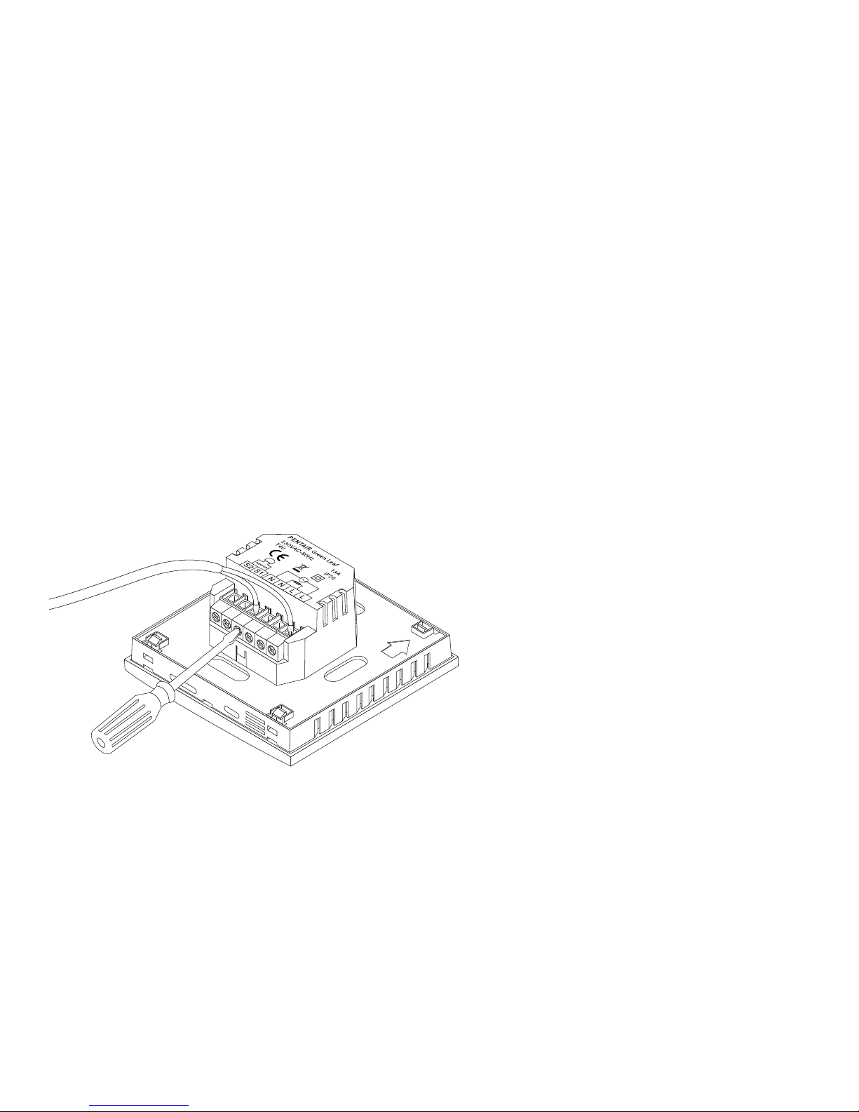
Step 1: Switch off the power supply
Step 2: Detach the metallic support from the Thermostat using a screwdriver
Step 3: Screw the metallic support frame to the in-wall box
Page 5
5
Step 4: Install the floor sensor (mandatory for floor sensing mode or room sensing mode with floor
temperature limiter). The floor sensor should be installed in a separate flexible conduit all the
way to the end, covering the end of the sensor, for easy replacement and to avoid possible signal
disturbance on the sensor. For best control performance, position the floor sensor between two
heating cables as close as possible to the top floor surface.
Do not position the floor sensor tip closer than 3 cm to the heating cable.
The floor sensor cable can be extended up to 100 m with a separate standard installation cable 2 x
1.5 mm
2
(230VAC).
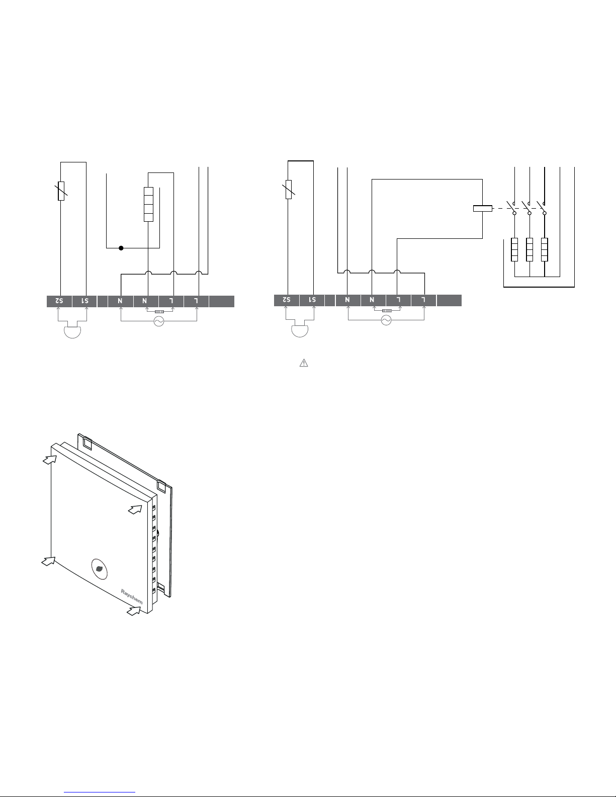
Step 5: Connect the electrical power supply, the sensor and the cold lead of the electrical floor
heating system to the Green Leaf according to the electrical diagram. If you connect heating cables
exceeding 13A for constant wattage or 10A for self-regulating cables you must use a contactor with
an integrated suppression device.
For the earth connection of the floor heating, you must use a separate earth terminal connection
block.
Page 6
6
Step 6: Click the Green Leaf into the metallic support frame.
Step 7: Switch on the power again
NTC
Floor
Sensor
Heating cable
230 VAC
Max. 13A*
Power supply
230 VAC
Direct connection - e.g. single heating circuit
* Max 13A for constant wattage cable,
Max 10A for self-regulating cables
10KΩ
N
L
L N
PE
PE
PE
NTC
Floor
Sensor
Power supply
heating cables
Connection via contactor - e.g. 3 heating circuits
Do not use contactor without suppression device.
L N
L1
12345
6
L2 L3PEN
N N N
L L L
PE
A1
A2
K1
Power supply
230 VAC
K1: contactor with
integrated
suppression device
10KΩ
SENSOR
SENSOR
NTC
Floor
Sensor
Power supply
heating cables
Connection via contactor - e.g. 3 heating circuits
Do not use contactor without suppression device.
L N
L1
12345
6
L2 L3PEN
N N N
L L L
PE
A1
A2
K1
Power supply
230 VAC
K1: contactor with
integrated
suppression device
10KΩ
SENSOR
Page 7

7
Product specific information
The thermostat is compatible with CeraPro, T2QuickNet, T2Blue, T2Green and T2Red heating
solutions.
T2QuickNet
T2QuickNet heating mats are approved with the Green Leaf thermostat working in floor sensor
mode. Be aware that the floor sensor must be installed and activated for any installation with
T2QuickNet.
T2Red
Self-regulating heating cables have an inrush current when the floor is cold. In order to guarantee the life
time of the thermostat, the maximum load of the self-regulating application in nominal conditions is
limited to 10A.
A 13A self-regulating load will reduce the life time of the relay contacts.
3.USING THE THERMOSTAT
The Display
Display in manual on/off programme
The following icons are visible in the Manual ON/OFF:
Active sensor display
• Floor sensing mode (
)
• Room Sensing mode (
)
• Room Sensing mode with Floor temperature limiter (
)
Page 8

8
Heating display
The heating display is flashing when the heating is on.
Temperature
The temperature on the display depends on the selected sensing mode.
• Floor sensing mode => Actual floor temperature on the display
• Room sensing mode => Actual room temperature on the display
• Room sensing with floor temperature limiter mode => Actual room
temperature on the display
Remark: When pushing on the “
” or “ ” button, the set point
temperature appears on the display blinking for 5 seconds
Installer Menu
• Touch the M button for 5 seconds to enter the Installer Menu
Display in timer programme
The following icons are visible in the Timer Programme:
Time and day
The actual day is displayed on the screen with the 3 letters
(MON-TUE-WED-THU-FRI-SAT-SUN).
The time can be set in 24H or 12AM/PM mode (see INSTALLER MENU).
Page 9

9
4 Event display
The 4 events are displayed with the symbols:
Event 1
Event 2
Event 3
Event 4
The manual on/off programme
When switching on the thermostat for the first time (touching the Green Leaf button for 2 seconds),
it will start in MANUAL ON/OFF programme using the floor sensing mode as a standard (see
INSTALLER MENU to change the sensing mode).
You will see the following screen:
Touch “ ” or “ ” to show the set point temperature.
It will blink for 5 seconds.
1. Touch “
” to decrease the temperature.
2. Touch “
” to decrease the temperature.
To switch from Manual ON/OFF to Timer Programme,
touch the “ ” button once.
To switch off the thermostat, touch the “
” button for 2 seconds.
Page 10

10
The timer programme
The Green Leaf can be programmed with 4 events per day. Different temperatures can be maintained
for each event of the day. The days can be programmed independently or per cluster of days.
The default Timer Programme is shown on the graph below. You can easily adapt the programme to
your needs (see PROGRAMMING THE TIMER PROGRAMME)
25
20
15
10
5
0
0:00
1:00
2:00
3:00
4:00
5:00
6:00
7:00
8:00
9:00
MON-TUE-WED-THU-FRI SAT-SUN
16
23
23
16
16
25
20
15
10
5
0
0:00
1:00
2:00
3:00
4:00
5:00
6:00
7:00
8:00
9:00
10:00
11:00
12:00
13:00
14:00
15:00
16:00
17:00
18:00
19:00
20:00
21:00
22:00
23:00
0:00
1:00
2:00
3:00
4:00
5:00
6:00
7:00
8:00
9:00
10:00
11:00
12:00
13:00
14:00
15:00
16:00
17:00
18:00
19:00
20:00
21:00
22:00
23:00
25
20
15
10
5
0
MON-TUE-WED-THU-FRI SAT-SUN
16
16
23
23 23
16
16
• Touch the “ ” button to set the clock and day of the week
• Touch the “
” button for 3 seconds to program the timer programme
(see page 14 for more details).
• Touch the “
” button for 5 seconds to enter the Installer Menu
• Touch the “
” button to switch from Timer to Manual ON/OFF mode
• Touch the “
” button for 2 seconds to put the Thermostat into OFF (standby) mode
• Touch “
” or “ ” to show the set point temperature. It will blink for 5 seconds
1. Touch “
” to decrease the temperature.
2. Touch “
” to decrease the temperature.
Remark: The adapted temperature is valid until the next timer Event.
Page 11

11
4. SETTING THE CLOCK
• Touch the “ ” button to set the clock
and day of the week
• Touch “
” or “ ” to change the hours
• Touch the “
” button to validate
• Touch “
” or “ ” to change the minutes
• Touch the “
” button to validate
• Touch “
” or “ ” to change the day of the week
• Touch the “
” button to validate
Remark: In case of battery drainage after long period of power failure, you might have to
re-programme the clock
5. PROGRAMMING THE TIMER PROGRAMME
• Touch the “ ” button for 3 seconds to program the Timer Programme
• Touch “
” or “ ” to choose the day (or the sequence of days) you want to program
• Touch the “
” button to validate
Day Sequences are:
MON
TUE
WED
THU
FRI
SAT
SUN
MON TUE WED THU FRI
SAT SUN
MON TUE WED THU FRI SAT SUN
Page 12

12
For Event 1
• Touch “ ” or “ ” to change hours of Event 1
• Touch the “
” button to validate
• Touch “
” or “ ” to change the minutes of Event 1
• Touch the “
” button to validate
• Touch “ ” or “ ” to change the temperature for Event 1
• Touch the “clock” button to validate
For Event 2, 3 and 4
• Repeat the actions for event 1 for the Events 2, 3 and 4
Touch the “
” button, at any time during the programming, to save your changes and return to the
Timer Programme.
If needed, you can repeat the complete procedure to program other days or sequences of days.
Page 13

13
6. INSTALLER MENU
Touch the “ ” button for 5 seconds to enter the installer Menu
# Description Range Default setting
1 Sensing mode selection Floor sensing mode
Room sensing mode
Room sensing mode with floor
temperature limiter
Floor Sensing mode
2 12 vs 24 hours display 12 / 24 24
3 Motion sensor. When getting
close to the thermostat
(5cm range) the display lights
up automatically
ON / OF ON
4 Offset for floor sensor
calibration
Offset of 0 .. 10°C 4°C
5 Room sensor calibration Measured sensor temperature
+/- 5°C
Measured sensor
temperature
6 Minimum temperature
set point for the Floor Sensor
Floor sensing mode: 5 .. 15°C
Room sensing mode: OF
Room sensing mode with floor
temperature limiter: OF
5°C
OF
OF
Page 14

14
# Description Range Default setting
7 Maximum temperature
set point for the
Floor Sensor
Floor sensing mode: Minimum
temperature set point floor
sensor (installer menu 6)
+5°C .. 35°C
Room sensing mode: OF
Room sensing mode with floor
temperature limiter: 10 .. 35°C
35°C
OF
27°C
8 Minimum temperature
set point for the Room Sensor
Floor sensing mode: OF
Room sensing mode: 5 .. 15°C
Room sensing mode with floor
temperature limiter: 5 .. 15°C
OF
5°C
5°C
9 Maximum temperature
set point for the Room Sensor
Floor sensing mode: OF
Room sensing mode: Minimum
temperature set point room
sensor (installer menu 8)
+5°C .. 40°C
Room sensing mode with floor
temperature limiter: Minimum
temperature set point room
sensor (installer menu 8)
+5°C .. 40°C
OF
40°C
40°C
10 Adjustable hysteresis 0.5 .. 2.0°C 1.0°C
Page 15

15
Floor sensor calibration
The temperature of the floor surface can differ from the temperature measured by the floor
sensor due to the floor construction, the floor type and the position of the floor sensor. In order
to calibrate your thermostat to this difference you can use the floor sensor calibration OFFSET in
installer Menu 4.
After the temperature on the floor is stabilized, place a thermometer on the floor surface in order to
sense the real temperature on the surface (Tsurface). Read the floor sensor temperature (Tsensor)
on the thermostat and adjust the OFFSET accordingly to the formula:
Tsensor
Tsurface
OFFSET = Tsensor - Tsurface
Room sensor calibration
If the value measured by the room sensor in the thermostat differs from the real room
temperature, it is possible to calibrate the room sensor using the installer Menu 5.
After the temperature in the room is stabilized, place a thermometer close to the wall in order
to sense the real room temperature. If this value differs from the one shown by the thermostat,
adjust Menu 5 using the “
” or the “ ” until the thermostat shows the same value as the reference
thermometer.
Page 16

16
7. TROUBLESHOOTING
In the event of damage or malfunction of one of the temperature sensors, the heating output cuts
off (fail safe) and an error code is displayed.
Error Code Description
ER1 Short circuit on floor sensor
ER2 Open circuit on floor sensor / Missing floor sensor
ER3 Short circuit on room sensor
ER4 Open circuit on room sensor
ER5 Check sensing mode
The floor sensor can be replaced by a new. In the event of malfunction
of the room sensor, the entire thermostat must be replaced (Error 3 or Error 4).
Error 5 occurs if the thermostat is set in Room Sensing Mode and the floor sensor is installed.
To resolve the error change the sensing mode in Floor sensing or Room sensing with floor
temperature limiter. Otherwise, remove the floor sensor to work in room sensing mode. The floor
sensor has got the following temperature/resistance values:
Temperature Resistance
15°C 15.8 kΩ
20°C 12.5 kΩ
25°C 10.0 kΩ
30°C 8.0 kΩ
35°C 6.5 kΩ
Page 17

17
8. TECHNICAL SPECIFICATION
Supply voltage 230VAC, +10%, –15%, 50Hz
Power consumption (Stand-by) 3 VA
Relay output 230V, maximum 13A resistive load (max. 3000W)
Ambient temperature – operation 0 .. 40°C, 5-95% RH (non condensing)
Ambient temperature – transport –10 .. +60°C
Temperature range, floor sensor +5 .. +35°C
Temperature range, room sensor +5 .. +40°C
Switching hysteresis
1°C (Factory settings adjustable between 0.5-2.0°C)
Control modes Floor sensing
Room sensing
Room sensing with floor temperature limiter
Temperature control Manual ON/OFF
Timer programme
Protection class IP 20
Terminals Max. 2,5 mm²
Floor sensor with 3 m cable NTC, 10KΩ / 25°C
Maximum length of floor sensor Cable 100 m, 2 x 1,5 mm² (230VAC cable type)
Approvals
Type of action 1.B. (39)*
Control pollution degree 2 (49)*
Rated impulse voltage 4kV (75)*
Temperature for the ball pressure test 125°C (77)*
SELV limits realized 22 VDC (86)*
* According to the EN 60730-1 table 1
Our products satisfy the requirements
of the relevant European Directives.
Page 18

18
Page 19

19
86.3
86.3
48.0
86.3
49.0
79.8 60.0
16.5
41.0
Dimensions
Page 20

THERMAL BUILDING SOLUTIONS
EN-RaychemGreenLeafEU-IM-EU0637 Rev0
WWW. PENTAIRTHERMAL.COM
All Pentair trademarks and logos are owned by Pentair or its global affiliates. Pentair reserves the right to change specifications without prior notice.
© 2013-2016 Pentair.
BELGIË / BELGIQUE
Tel. +32 16 21 35 02
Fax +32 16 21 36 04
salesbelux@pentair.com
BULGARIA
Tel./fax +359 56 86 68 86
fax +359 56 86 68 86
salesee@pentair.com
ČESKÁ REPUBLIKA
Tel. +420 241 009 215
Fax +420 241 009 219
czechinfo@pentair.com
DANMARK
Tel. +45 70 11 04 00
Fax +45 70 11 04 01
salesdk@pentair.com
DEUTSCHLAND
Tel. 0800 1818205
Fax 0800 1818204
salesde@pentair.com
ESPAÑA
Tel. +34 902 125 307
Fax +34 91 640 29 90
ptm-sales-es@pentair.com
FRANCE
Tél. 0800 906045
Fax 0800 906003
salesfr@pentair.com
HRVATSKA
Tel. +385 1 605 01 88
Fax +385 1 605 01 88
salesee@pentair.com
ITALIA
Tel. +39 02 577 61 51
Fax +39 02 577 61 55 28
salesit@pentair.com
LIETUVA/LATVIJA/EESTI
Tel. +370 5 2136633
Fax +370 5 2330084
info.baltic@pentair.com
MAGYARORSZÁG
Tel. +36 1 253 7617
Fax +36 1 253 7618
saleshu@pentair.com
NEDERLAND
Tel. 0800 0224978
Fax 0800 0224993
salesnl@pentair.com
NORGE
Tel. +47 66 81 79 90
Fax +47 66 80 83 92
salesno@pentair.com
ÖSTERREICH
Tel. 0800 297410
Fax 0800 297409
info-ptm-at@pentair.com
POLSKA
Tel. +48 22 331 29 50
Fax +48 22 331 29 51
salespl@pentair.com
REPUBLIC OF KAZAKHSTAN
Tel. +7 495 926 18 85
Fax +7 495 926 18 86
saleskz@pentair.com
РОССИЯ
Тел. +7 495 926 18 85
Факс +7 495 926 18 86
salesru@pentair.com
SERBIA AND MONTENEGRO
Tel. +381 230 401 770
Fax +381 230 401 770
salesee@pentair.com
SCHWEIZ / SUISSE
Tel. 0800 551308
Fax 0800 551309
info-ptm-ch@pentair.com
SUOMI
Puh. 0800 11 67 99
Telekopio 0800 11 86 74
salesfi@pentair.com
SVERIGE
Tel. +46 31 335 58 00
Fax +46 31 335 58 99
salesse@pentair.com
TÜRKIYE
Tel. +90 530 977 64 67
Fax +32 16 21 36 04
ptm-sales-tr@pentair.com
UNITED KINGDOM
Tel. 0800 969013
Fax 0800 968624
salesthermaluk@pentair.com
 Loading...