

Page 1
Hazardous locations
WARNING:
E507S-LS
Line-Sensing Thermostat for Hazardous Locations
Installation Instructions
DESCRIPTION
The nVent RAYCHEM E507S-LS thermostat is designed for controlling
heat-tracing systems in hazardous locations. TheE507S-LS can be
used to control heat-tracing circuits in apipe-sensing mode (see
Figure 1 on back page), to indicate low-temperature (see Figure 2) or
Pentair
high-temperature (see Figure 3) alarm conditions, or to control the coil
on a contactor (see Figure 4).
APPROVALS
Class I, Div. 1 and 2, Groups B, C, D
Class II, Div. 1 and 2, Groups E, F, G
Class III
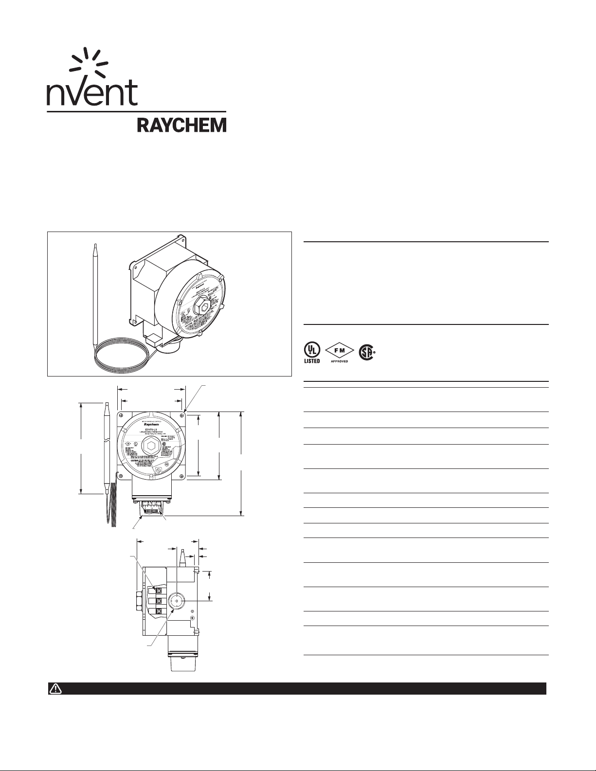
8.0 in.
(202 mm)
Terminal
block
3⁄4 in. NPT conduit entry
4.5 in. (114 mm)
4.0 in. (102 mm)
Pentair
Adjusting knob
Removable knob cover
4.0 in. (102 mm)
4.0 in.
(102 mm)
2.0 in.
(50 mm)
Ø.28 in. (7 mm)
mounting hole
(4X)
4.5 in.
(114 mm)
6.6 in.
(168 mm)
1.2 in. (30 mm)
0.3 in. (9 mm)
SPECIFICATIONS
Enclosure NEMA 4, 7, 9, lacquer-coated cast-aluminum
housing, stainless-steel hardware
Entries One 3/4 in. NPT conduit hub
Set point range 25°F to 325°F (–4°C to 163°C)
Sensor exposure
limits
Housing exposure
limits
Switch SPDT
Electrical rating 22 A at 125/250/480 Vac
Accuracy ±6°F (±3.3°C)
Deadband 2°F to 12°F (1.1°C to 6.7°C) above actuation
Set point
repeatability
Sensor type Fluid-filled (silicone) bulb and 9 ft (2.7 m)
Sensor material 300 series stainless steel
Connection
terminals
–40°F to 420°F (–40°C to 215°C)
–40°F to 140°F (–40°C to 60°C)
temperature
±3°F (±1.7°C)
capillary
Screw terminals, 10–14 AWG (2–5 mm2)
This component is an electrical device. It must be installed correctly to ensure
proper operation and to prevent shock or fire. Read these important warnings
and carefully follow all the installation instructions.
Component approvals and performance are based on the use of specified parts
only. Do not use substitute parts or vinyl electrical tape to make connections.
Page 2
INSTALLING THE THERMOSTAT
1. Verify that the thermostat is
suitable for the area where it is to be
Pentair
installed.
2. Check the line voltage and the
heat-tracing load to ensure that the
thermostat ratings are not exceeded.
3. Mount the unit using unistrut or the RAYCHEM universal
mounting bracket (UMB-263757) in a position that prevents
condensation from draining into the enclosure from the
connecting conduit (see diagram above).
POSITIONING THE SENSOR BULB
4. Position the bulb in the
lower quadrant of the pipe
as shown in the diagrams
to the left. Place the bulb
at least three feet from
pipe supports, valves, or
other heat sinks; protect the
capillary from kinks or bends
less than 1⁄2 inch in radius.
90
Single traced
Heating cable
Control thermostat bulb
AT-180 tape
Double traced
Heating cable
Control thermostat bulb
AT-180 tape
Conduit
drain
5. Tape the bulb firmly to the pipe with AT-180 aluminum tape,
making sure there is no air space between the bulb and pipe.
Donot overlap the bulb and heating cable with the same piece
ofAT-180 tape.
6. For metal-tank-wall sensing, use the BCK-35 bulb clamp
(purchased separately) and install the clamp per the instructions
provided. Make sure there is no air space between the tank wall
and the bulb.
For installation on plastic tanks, contact nVent at (800) 545-6258.
SETTING THE THERMOSTAT
7. Set the thermostat dial to the desired temperature, then finish
wiring.
8. Complete insulating. Do not turn the system on until the bulb is
covered with thermal insulation.
9. Fill the piping or tank. Once the thermostat has begun to cycle,
check the fluid temperature with an immersed thermostat (best
for plastic systems) or an accurate temperature indicator. Adjust
the dial setting if necessary.
WIRING
GFEPD
ØØ
208-V or 240-V supply – 240-V heater
or
G
120-V supply – 120-V heater
N
Ø
277-V supply – 240-V heater
C
NO NC
Power
G
connection
Thermostat bulb
Braid
(see "Positioning"
instructions above
for mounting details)
Heating
Cable
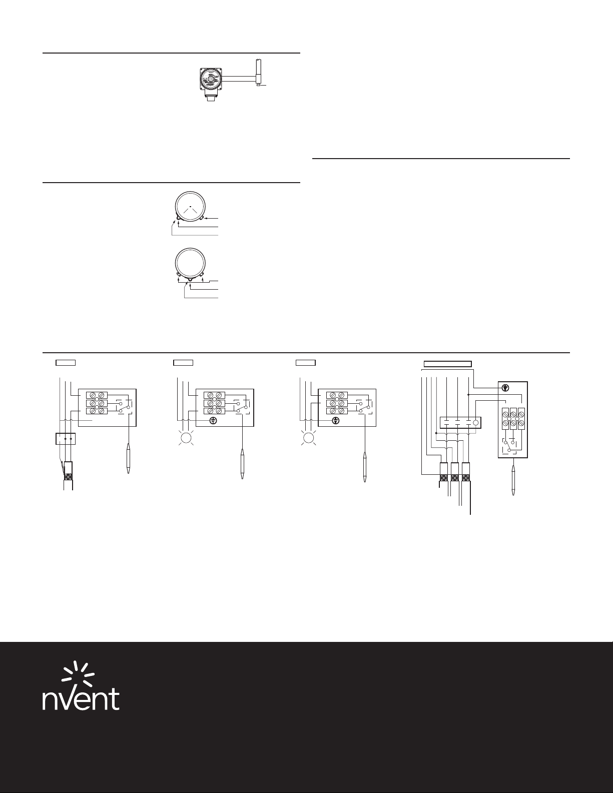
Figure 1. Pipe-sensing
North America
Tel +1.800.545.6258
Fax +1.800.527.5703
[email protected]
GFEPD
208-V or 240-V supply
ØØ
or
ØGN
120-V supply – 120-V heater
277-V supply – 240-V heater
Control
thermostat
Alarm
for mounting details)
Figure 2. Low-temperature alarm
Europe, Middle East, Africa
Tel +32.16.213.511
Fax +32.16.213.604
[email protected]
C
NO NC
Thermostat bulb
(see "Positioning"
instructions above
Control
thermostat
GFEPD
208-V or 240-V supply
ØØ
or
ØGN
120-V supply – 120-V heater
277-V supply – 240-V heater
C
NO NC
Alarm
Thermostat bulb
(see "Positioning"
instructions above
for mounting details)
Figure 3. High-temperature alarm
Asia Pacific
Tel +86.21.2412.1688
Fax +86.21.5426.3167
[email protected]
Control
thermostat
GCNANBN
Braid
C
Heating
cable A
GFEPD
Heating
cable B
A
120- V supply – 120-V heater or
Ø
ØBØ
C
277-V supply – 240-V heater
120-V or
277-V
coil
Heating
cable C
NONC
C
NONC
C
Thermostat bulb
(see "Positioning"
instructions above
for mounting details)
Figure 4. Contactor control
For switching heat-tracing loads greater than 22 A
or switching multiple heat-tracing circuits.
Latin America
Tel +1.713.868.4800
Fax +1.713.868.2333
[email protected]
Control
thermostat
nVent.com
©2018 nVent. All nVent marks and logos are owned or licensed by nVent Services GmbH or its affiliates. All other trademarks are the property of their respective owners.
nVent reserves the right to change specifications without notice.
Raychem-IM-H56913-E507SLS-EN-1805 PN 137863
 Loading...