

Page 1
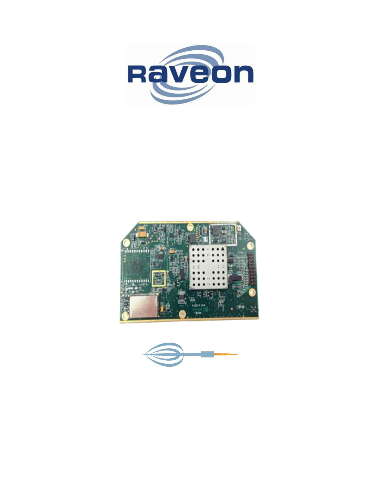
RV- M8-UC
D ART 450- 4 7 0 M H z
D at a M o d em
T ec h n i c al M a n u a l
Version A2
Feb 2015
Company Confidential 1 Raveon Technologies Corp.
Raveon Technologies Corporation
2320 Cousteau Ct.
Vista, CA 92081
www.raveon.com
Page 2

Table of Contents
1. General Information about the RV-M8-UC .................................................... 3
1.1. Congratulations! ............................................................................................................................. 3
1.2. NOTICE ......................................................................................................................................... 3
1.3. Safety / Warning Information ......................................................................................................... 3
1.4. Part 15 Note: ................................................................................... Error! Bookmark not defined.
2. Overview ....................................................................................................... 5
2.1. Features......................................................................................................................................... 5
2.2. Firmware Updating ........................................................................................................................ 6
2.3. General .......................................................................................................................................... 7
2.4. Transmitter Specifications (RV-M8-UC -xx) ................................................................................... 7
2.5. Receiver Specifications ................................................................................................................. 7
2.6. Interface Specifications .................................................................................................................. 7
3. Electrical Inputs and Outputs ......................................................................... 9
3.1. RS-232/EIA232 Serial I/O Connector ............................................................................................ 9
3.2. GPS (-GX option) ......................................................................................................................... 10
4. User Serial Port Commands ........................................................................ 11
4.1. Overview ...................................................................................................................................... 11
4.2. Command Mode .......................................................................................................................... 11
4.3. Setting a Parameter ..................................................................................................................... 12
4.4. Reading a Parameter ................................................................................................................... 12
4.5. CONFIG Button ........................................................................................................................... 12
4.6. Exiting the Command Mode......................................................................................................... 13
5. Command Mode Commands ....................................................................... 14
5.1. General Common Commands ..................................................................................................... 14
5.2. Data Modem Mode Related Commands ...................................................................................... 16
5.3. DART Related Commands .......................................................................................................... 16
5.4. GPS Related Commands............................................................................................................. 17
5.5. Diagnostic Related Commands ................................................................................................... 17
5.6. Factory Default Settings............................................................................................................... 17
(DART Data Transceiver) .................................................................................................................... 17
6. Programming Channels and Frequencies ................................................... 18
6.1. Initializing a new RV-M8-UC to factory defaults .......................................................................... 18
7. Data Transmission ....................................................................................... 19
Serial Port Baud Rate .......................................................................................................................... 19
8. Debug Related Commands ......................................................................... 19
9. Diagnostic Provisions .................................................................................. 21
9.1. Overview of Diagnostics .............................................................................................................. 21
9.2. Reading the Diagnostic Information ............................................................................................. 21
9.3. Status and Statistics Command ................................................................................................... 21
10. Tune-up and Alignment ............................................................................ 22
10.1. Periodic Calibration ...................................................................................................................... 22
10.2. Calibration Commands ................................................................................................................ 22
10.3. Center Frequency ........................................................................................................................ 23
10.4. TX Deviation ................................................................................................................................ 23
10.5. TX Modulation Balance ................................................................................................................ 23
11. Mechanical ................................................................................................ 25
11.1. DC Input....................................................................................................................................... 25
Company Confidential 2 Raveon Technologies Corp.
Page 3

1. General Information about the RV-M8-UC
1.1. Congratulations!
Congratulations on your purchase of a RV-M8-UC OEM radio.
Please take a few minutes to read this manual carefully. The information presented here
will allow you to derive maximum performance from your radio modem. After reading it,
keep the manual handy for quick reference, in case questions arise later on.
1.2. NOTICE
There are no user-serviceable points inside this transceiver. All service work must be
referred to your Authorized Service Center or Raveon Technologies Service Department.
IMPORTANT NOTICE !
Because of the nature of wireless communication, transmission and reception of data can never be
guaranteed. Data may be delayed, corrupted (i.e., have errors), or be totally lost. Significant delays
or losses of data are rare when wireless devices, such as the Viper SC, are used in a normal
manner with a well-constructed network.
This radio should not be used in situations where failure to transmit or receive data could result in
damage of any kind to the user or any other party, including but not limited to personal injury, death,
or loss of property.
Raveon accepts no responsibility for damages of any kind resulting from delays or errors in data
transmitted or received using Viper SC, or for the failure of Viper SC to transmit or receive such
data.
1.3. Safety / Warning Information
Service
This equipment should be serviced by qualified technicians only.
Blasting Caps and Blasting Areas
To avoid possible interference with blasting operations, turn off this radio or remove the DC
power when you are near electrical blasting caps, in a blasting area, or in areas posted:
“Turn off two-way radio.” Obey all signs and instructions.
Potentially Explosive Atmospheres
Turn off your radio prior to entering any area with a potentially explosive atmosphere. Do
not install this product for use in areas with potentially explosive atmospheres. Do not
remove, install, or charge batteries in such areas. Sparks in a potentially explosive
atmosphere can cause an explosion or fire resulting in bodily injury or even death.
Note: The areas with potentially explosive atmospheres referred to above include fueling areas such as
below decks on boats, fuel or chemical transfer or storage facilities, areas where the air contains chemicals or
particles, such as grain, dust or metal powders, and any other area where you would normally be advised to
turn off your vehicle engine. Areas with potentially explosive atmospheres are often but not always posted.
Company Confidential 3 Raveon Technologies Corp.
Page 4
FCC MPE Regulations:
WARNING: It is the responsibility of the user to guarantee compliance with the FCC MPE
regulations when operating this device in a way other than described in this manual.
Human body Exposure:
This equipment is approved only for mobile and base station transmitting devices,
separation distances of
(i) 80 centimeters or more for antennas with gains of 0 dBi or less or
(ii) 1 meters or more for antennas with gains 0 to 6 dBi should be maintained
between the antenna of this device and nearby persons during operation. To
ensure compliance, operation at distances closer than this is not recommended
and the EUT has not been approved for operation with antennas having a gain
that exceeds 6 dBi.
1.4. Part 15 Note:
This equipment generates, uses and can radiate radio frequency energy and, if not
installed and used in accordance with the instructions, may cause harmful interference to
radio communications. However, there is no guarantee that interference will not occur in a
particular installation. If this equipment does cause harmful interference to radio or
television reception, which can be determined by turning the equipment off and on, the user
is encouraged to try to correct the interference by one or more of the following measures:
Reorient or relocate the receiving antenna.
Increase the separation between the equipment and receiver.
Connect the equipment into an outlet on a circuit different from that to which the
receiver is connected.
Consult the dealer or an experienced radio/TV technician for help.
Company Confidential 4 Raveon Technologies Corp.
Page 5

2. Overview
The RV-M8-UC RF DART compliant Data radio modem is capable of high-speed narrowband data communications. It contains a receiver, a transmitter, and modem, creating an
easy-to-use transparent data radio link. The built-in DART protocol is compatible with
Raveon’s DART data radio protocol. (www.raveon.com/DART ) This radio modem is not
compatible with Raveon’s M7 series of data radio modems.
The RV-M8-UC ’s user interface is asynchronous digital data into and out of the RV-M8-UC
. Modem operation is virtually transparent to the user and the configuration of the modem
is via the user serial port.
The command-line interface is similar to Raveon’s other data radio products, and
configuring the mode is very easy. The RV-M8-UC is an easy to use and its reprogrammability makes it extremely versatile. Most parameters within the modem may be
re-configured to optimize it for specialized operations, extended range, or higher data
throughput.
2.1. Features
General Features
Serial input and output. Programmable serial baud rates up to 57600.
Small sized and single-board construction.
Very efficient circuitry. ( < 700mW receiving, < 8W transmitting)
Easy to use. Transmit data in = Receive data out.
Easily configured using “AT” commands
Extensive diagnostic capabilities
WMX serial protocol may be enabled on the serial port..
Wide input voltage with high-efficiency switching voltage regulator.
DART Radio Modem Features
Quickly deploy new radios into complex systems
Configures radio modems dynamically, based upon current system needs and settings.
Over-the-air channel/frequency assignments
Data transmission bandwidth allocation
Assigns channel bandwidth dynamically to devices needing to communicate
Retry interval and duration is managed by local base station based on loading and QOS
Wireless Devices (WDs) automatically find the a local base station to link-up to when they power on.
Balance the data communication loads based upon device priorities, system configuration and minimum QOS
WDs may be assigned to groups. Single messages may be sent to groups of WDs. Messages may be routed
to/from groups.
Company Confidential 5 Raveon Technologies Corp.
Page 6

2.2. Firmware Updating
The RV-M8-UC is a software based radio and modem. There are times an existing unit
needs to get updated with a new feature, and this can often be done by loading the new
firmware into the older radio modem. In firmware program called the “Boot Loader” is
permanently installed inside the RV-M8-UC ’s microcontroller. During power up, it checks
to see if the user wants to update the application program in the microcontroller.
Company Confidential 6 Raveon Technologies Corp.
Page 7

Specifications
2.3. General
Model Number, transceiver: ............................................................. RV-M8-UC -X
RF Power Output ............................................................................... 1.0W – 5.0 W (programmable)
IF Bandwidth ...................................................................................... 12.5kHz standard, 25kHz optional (-W)
Serial Port Baud Rates ...................................................................... 1.2k, 2.4k, 4.8k, 9.6k, 19.2k, 38.4k, 57.6k, 115.2k
Over-the-air baud rates .................................................................... 1200, 2400, 4800, 9600
Operating Mode ................................................................................. DART over-the-air protocol
Full Spec Operating Temperature range ......................................... -30°C to +60°C
Wake-up time ..................................................................................... <700mS from OFF
RF I/O Connector ............................................................................... MMCX female
Enable Input Low............................................................................... 400mV
Digital Output High (1K load) ......................................................... 3.0 - 3.3V
Digital Output Low (1K load) .......................................................... 0 - 0.2V
Digital Input High ............................................................................. > 3.0V
Digital Input Low .............................................................................. < 0.3V
Enable input High .............................................................................. 1.40V
2.4. Transmitter Specifications (RV-M8-UC -xx)
RF Power Output ............................................................................... 1W – 5 W (programmable)
Frequency Range (-UC) .................................................................... 450-470MHz
Maximum Duty Cycle (1W) ............................................................. 50% to 40C, 20% to 60C
Maximum Duty Cycle (5W, measured over 60 seconds) .............. 10% to 50C, 5% to 60C
Frequency Deviation ......................................................................... ± 2.2kHz
Channel spacing ................................................................................. 12.5kHz
TX Spurious outputs .......................................................................... < -70dBc
Occupied Bandwidth ......................................................................... Per FCC
FCC Emissions Designator ............................................................... 8K20F1D, 11K0F1D
Frequency Stability ............................................................................ Better than ±1.0ppm
2.5. Receiver Specifications
Frequency Range (-UC) ........................................................................................... 450-470MHz
Data RX sensitivity (.1% BER), 19200bps Wideband ............................................ < -110dBm
Data RX sensitivity (.1% BER), 9600bps Narrowband ......................................... < -110dBm
Data RX sensitivity (.1% BER), 1200bps ................................................................. < -116dBm
Current Consumption .............................................................................................. <120mA at 12.5V DC input
Channel spacing ........................................................................................................ 12.5kHz or 25kHz (-N or –N )
Adjacent Channel Selectivity 12.5kHz ................................................................... -50dB
Alternate Channel Selectivity .................................................................................. -60dB
Blocking and spurious rejection .............................................................................. -70dB
RX intermodulation rejection .................................................................................. -70dB
2.6. Interface Specifications
DC Input
Connector on front panel ......................................................................................... 3-pin M8 type
Raveon P/N ...............................................................................................................
Serial Port
Company Confidential 7 Raveon Technologies Corp.
Page 8

Serial connector type ................................................................................................ DB9 RS 232 serial
IO Voltage Levels ...................................................................................................... RS232
RX and TX data ......................................................................................................... Transparent Async
Word length ............................................................................................................... 8 bits
Format ........................................................................................................................ N, O, or Even parity, 1 stop
Other
RF connector ....................................................................................... TNC Female
Company Confidential 8 Raveon Technologies Corp.
Page 9
3. Electrical Inputs and Outputs
Pin
Name
Dir
Function
Level / Specification
1
CD
out
Carrier detect
If enabled, indicates presence of carrier.
Logical 0 (+ voltage on RS-232) means
carrier is present. If disabled, it is
asserted (0) whenever the modem is
operational, and not in the configuration
mode. It will be a 1 when the modem is
in the configuration mode. Configured
with the ATR1 setting.
2
RxD
out
Receive data
Data out of the modem.
3
TxD
in
Transmit data
Data into the modem.
4
DTR
in
Data terminal
ready
Normally ignored by the M7 modem.
May control the power-state of the
modem in low-power mode if this
feature is enabled.
5
GND Ground
connection
Signal and power ground
6
DSR
out
Data Set
Ready
Normally is set to 0 when modem is
powered on and running. Modem sets
to a 1 when in low-power mode or in
command mode.
7
RTS
in
Request to
send
Used to stop/start the flow of data
coming out of the modem TxD pin. 0 =
OK to send, 1 = don’t send. Leave
disconnected if not used.
8
CTS
out
Clear to send
Used to stop the flow of data going into
the RxD pin from the device connected
to the M7. 0 = OK to send, 1 = don’t
send. If the M7 cannot accept more
data, it will negate this signal (set to a
1).
9
Power
In/o
ut
DC power (not
Ring signal)
User may supply the DC power to the
modem on this pin.
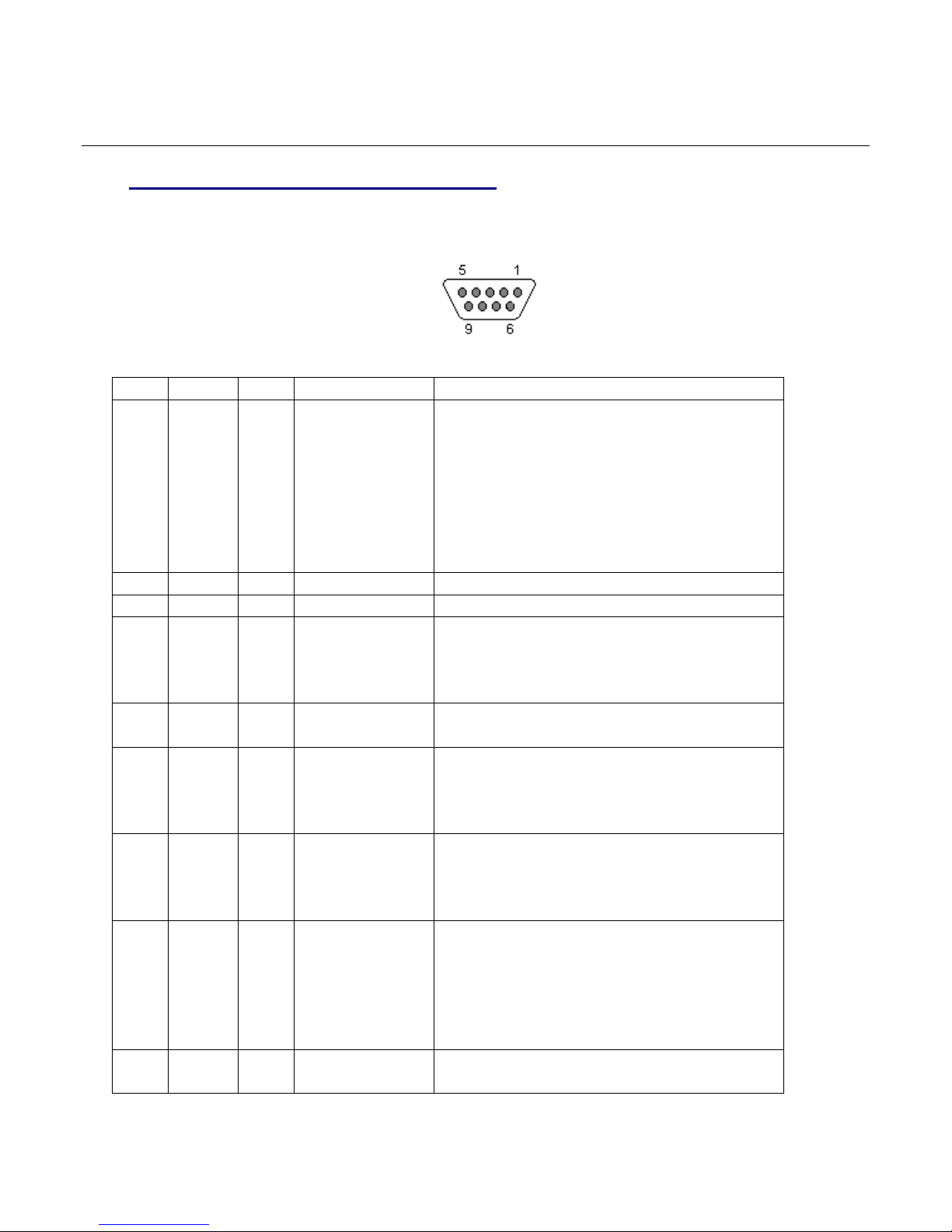
3.1. RS-232/EIA232 Serial I/O Connector
The RS-232 9-pin serial I/O connector is a female 9-pin D-subminiature connector having
the following pins configuration. It is pinned out so that it may be plugged directly into a
computer or PC’s 9-pin COM port.
Front-view of DB-9 connector on modem (female)
Company Confidential 9 Raveon Technologies Corp.
Page 10

3.2. GPS (-GX option)
GPS receiver for position tracking utilizes a MAX-7 GPS receiver.
MAX 7 Product description
The MAX-7 series is the newest family of standalone GPS/GNSS modules from u-blox. With the
exceptional performance of the u-blox 7 multi-GNSS (GPS, GLONASS, Galileo, QZSS and
SBAS) engine, the MAX-7 series delivers high sensitivity and minimal acquisition times in the
ultra compact MAX form factor.
The MAX-7 series provides maximum sensitivity while maintaining low system power. The MAX7C is optimized for cost sensitive applications. The MAX-7Q provides best performance
and lowest power, while the MAX-7W provides best performance and is optimized for active
antennas. The industry proven MAX form factor allows easy migration from MAX-6 modules.
Sophisticated RF-architecture and interference suppression ensure maximum performance
even in GPS-hostile environments.
The MAX-7 series combines a high level of integration capability with flexible connectivity
options in a miniature package. This makes it perfectly suited for industrial and mass-market
end products with strict size and cost requirements. The DDC (I2C compliant) interface provides
connectivity and enables synergies with u-blox SARA, LEON and LISA wireless modules. u-blox
7 modules use GPS/GNSS chips qualified according to AEC-Q100
Company Confidential 10 Raveon Technologies Corp.
Page 11

4. User Serial Port Commands
4.1. Overview
The serial portion the RF modem is used to send and receive data over the
air, as well as to configure the RF modem. In normal operation, the user
sends data into the TXD pin of the IO connector, and this data is transmitted
over the air. Received data from another RF modem is output to the user via
the RXD pin of the IO connector. This is the default operating condition of the
RF modem. No special characters, hardware control lines, or timing is
required to operate the RV-M8-UC modem.
There is also a “Command Mode” used to program and configure the M8. In
the Command Mode, the RV-M8-UC modem accepts commands via the
serial port TxD pin. The commands can be used to change certain internal
parameters of the RV-M8-UC modem as well as to read-out the current
configuration and diagnostic statistics.
4.2. Command Mode
The RV-M8-UC modem may be put into a “Command Mode”, by entering a
sequence of three plus characters (+++). To keep the RV-M8-UC modem
from unintentionally entering the Command Mode because of the +++ pattern
occurring in a stream of data entering the modem, there must be a pause in
the data stream before the +++ as well as a pause after the +++ is sent. If
either pause is missing, the modem will not enter the command mode.
Using serial communications software such as HypterTerminal, send the 3-
character command sequence “+++” while observing times of silence before
[BT (Silence Before Sequence) Command] and after [AT (Silence After
Sequence) Command] the command characters. The default BT and AT
times are 500mS.
The default sequence for entering into AT Command Mode:
1. No characters sent for ½ a second.
2. Input three (3) plus characters (“+++”) within ½ of a
second.
3. No characters sent for ½ a second.
When the RV-M8-UC modem first enters the Command Mode, it sends the
phrase
Raveon RV-M8-UC (transceiver version)
or
Raveon M8R (receive only version)
out of its serial port, and then an “OK” sequence. The “OK” sequence is a
sequence of 4 characters:
An “O”, “K”, <CR>, and <LF> characters
(<CR> = ASCII 0D, <LF> = ASCII 0A)
Company Confidential 11 Raveon Technologies Corp.
Page 12

4.3. Setting a Parameter
To set a parameter in the RV-M8-UC modem, enter the Command Mode as
described above. Then enter the proper AT command, a space, the
parameter, and then a carriage return. For Example, to set the address of the
RV-M8-UC modem to 1234, enter the following command:
ATDT 1234 <CR>
Once a Parameter is changed, the modem will begin using the new
parameter and the new parameter is saved to non-volatile.
4.4. Reading a Parameter
To read the value of a particular setting, issue the command, with no
parameter. The modem will return the value followed by an “OK”. The
modem’s OK response is:
The value in ASCII decimal format.
A <CR> <LF> (<CD> = ASCII 0D, <LF> = ASCII 0A).
An “O”, “K”, <CR>, and <LF> sequence.
For example, if the user enters the command to read the M8’s modem
address and its address was 1234, the user would issue the following
command:
ATDT<cr>
and the modem will respond with:
1234 <CR> <LF> OK <CR> <LF>
To get on-line help with a command, enter the command and put a question
mark in for the parameter. For example, to see what the ATDT command is
for, type:
ATDT ?
The modem will respond by listing a brief description of the command. To
see a list of all commands, type HELP.
Many commands support the “MIN” and “MAX” parameters to read the
minimum and maximum allowable settings. For example, type ATJF MAX to
find the maximum value the CTS negation threshold may be set to.
4.5. CONFIG Button
If certain parameters within the modem are modified in a manor that causes
the modem to cease functioning or if the user cannot enter the command
mode via the “+++” method described above, there is a small push button
internal to the RV-M8-UC modem to assist in this case. This CONFIG button
may be pressed at any time, and forces the modem into a known operational
state. The CONFIG button is located inside the modem. Remove the rear
Company Confidential 12 Raveon Technologies Corp.
Page 13

cover, exposing the two circuit boards. The button is in the front edge of the
radio module’s circuit board.
The default settings that the modem will revert to when the CONFIG button is
pressed are:
1. Serial port 9600 baud, 8 data bits 1 stop, no parity
2. ATCT setting set to 60000 (60 second time-out)
3. Serial port on the front of the unit in RS232 mode, 9600bps, N/8/1.
Even though the serial baud rate reverts to 9600 baud when the CONFIG
button is pressed and the IO port is RS232, it will revert back to the settings
programmed into the RV-M8-UC modem once the Command Mode is exited.
4.6. Exiting the Command Mode
There are three ways to exit the command mode. They are:
1. ATCN Issuing the ATCN. The RV-M8-UC radio will exit the command
mode, and begin normal operation.
2. EXIT Issuing the EXIT. The RV-M8-UC radio will exit the command
mode, and begin normal operation.
3. Time Out. After a pre-set amount of time (60 seconds is the factory
default time), the modem will automatically exit the Command Mode, and
continue normal operation. Changes will not automatically be saved. This
time-out duration may be set with the ATCT command.
Company Confidential 13 Raveon Technologies Corp.
Page 14
5. Command Mode Commands
Command
Command Description
Parameters
Factory
Default
ATAT
Silence AFTER Sequence - Sets period of silence after the
command sequence characters in mS.
Range:0 – 1000
(mS)
500
ATBD
Baud Rate – Sets serial com port baud rate (bps). Type the
range index (0-7) or the actual desired baud rate.
Range: 0 – 7
0 = 1200 5=
38400
1 = 2400
6=57600
2 = 4800
7=115200
3 = 9600
4 = 19200
3
ATBT
Silence BEFORE Sequence – Sets period of silence before
the command sequence character in mS.
Range: 0-1000
mS
500
ATCD
Carrier Detect Threshold – Read/set the carrier detect
threshold, in dBm. -113 means -113dBm.
-113
-120 to -60
ATCH
Configure Hardware Flow Control – Enable (1) or disable (0)
flow control. When enabled, the modem will monitor the RTS
line, and if it is negated, stop sending data out the serial port. If
disabled, the modem will ignore the state of RTS, and always
send out characters.
1 = Enable
0 = Disable
0
ATCT
Command Time Out – If no valid commands have been
received via the serial port within this time period (in
milliseconds), modem returns to normal operation mode from
Command mode. If the CONFIG button inside the RV-M8-UC
is pressed, this parameter will be automatically set to 60000.
Range: 10060000mS
60000
ATE
Echo – Character echo set on (E1) or off (E0). This applies to
the Command Mode only.
Range: 0 , 1
1 (echo)
ATFC
Set/read channel – Program the transmit frequency for this
channel. Enter in Hz or in MHz.
ATFC cc tt rr oo Where cc is the channel number, tt is the TX
frequency, rr is the RX frequency, oo is optional.
If oo is included, it is stored as the channel option bits. oo is a
two digit HEX parameter.
Enter ATFC ALL to display all channels.
ATFS
Show frequencies – Display all of the frequencies
programmed into all of the channel memories.
N/A
ATFT
Transmit Frequency – Program the transmit frequency for this
channel. Enter in Hz or in MHz. The frequency will
automatically be saved in non-volatile memory (flash) for this
current channel number.
Range: See product
data sheet. For MURS
products, frequency
cannot be changed.
See product data
sheet.
ATFR
Receive Frequency – Program the receive frequency for this
channel. Enter in Hz or MHz. The frequency will automatically
be saved in non-volatile memory (flash) for this current channel
number.
Range: See product
data sheet. For MURS
products, frequency
cannot be changed.
See product data
sheet.
ATFX
TX and RX Frequency – Program the receive and transmit
frequency for this channel. Enter in Hz or MHz. Same as
Range: See product
data sheet.
N/A
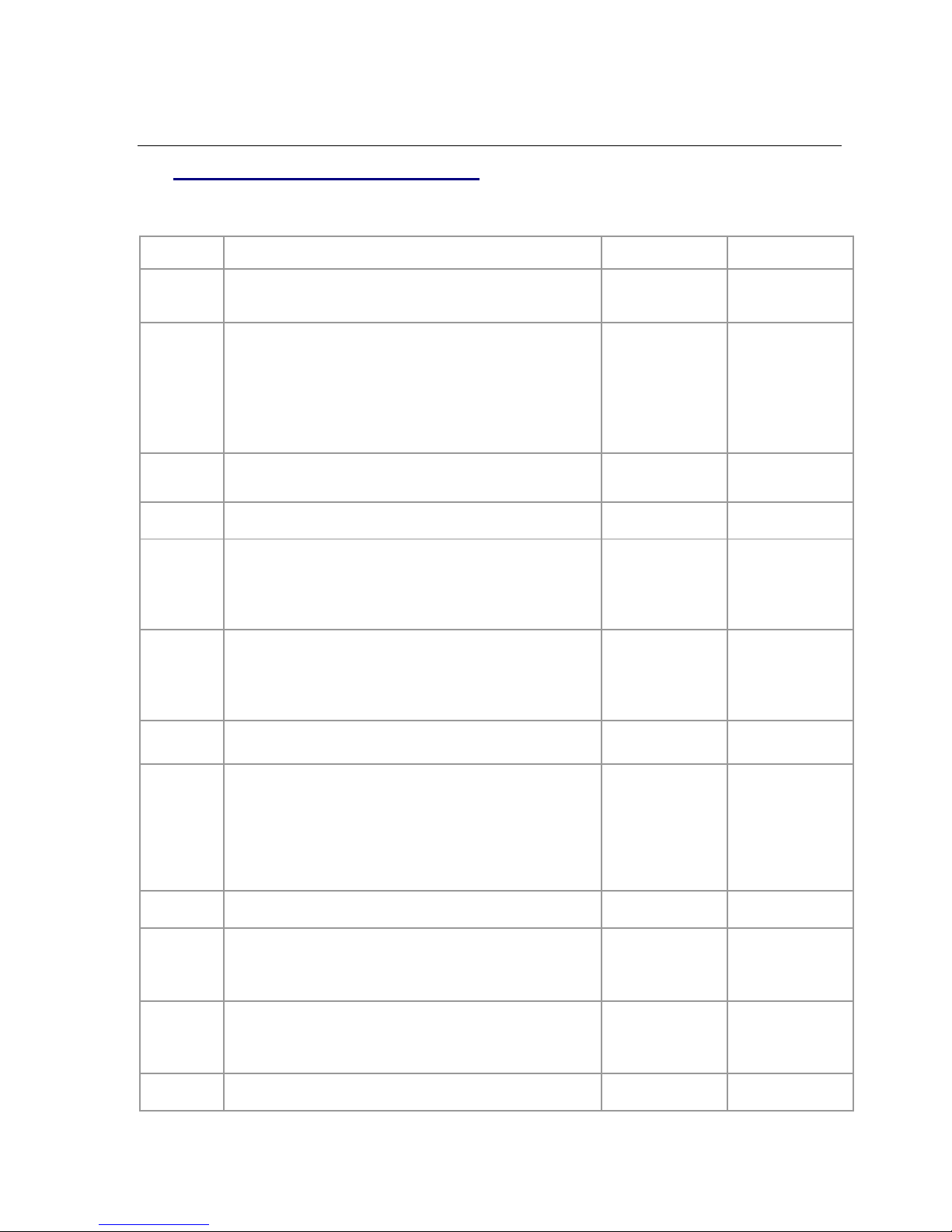
5.1. General Common Commands
These commands apply to the general configuration of the RV-M8-UC,
and are applicable in both the data modem mode and paging mode.
Company Confidential 14 Raveon Technologies Corp.
Page 15
issuing an ATFR and an ATFT command. The frequency will
automatically be saved in non-volatile memory (flash) for this
current channel number.
ATHP
Channel Number – Select current radio channel number. The
channel number is stored in EEPROM memory.
Range: 1 - 6
1
ATIC
Read Current Draw Read the current draw in mA. Accuracy is
within 20% of actual current draw.
Range: 0-9999
N/A
ATL
Enable/Disable the LEDs – 1 = LEDs always off. This reduces
some power consumption. 0 = LED operate normally.
0 or 1
0
ATMT
Protocol Select – The over-the-air communication protocol.
0=Packetized mode, 5=DART
Range: 0 or 5
5
ATNB
Parity – Selects parity format. Settings 0-4 transfer 8-bits over
antenna port and generate the parity bit on the RF receiving side.
Range: 0 – 5
0 = none
1 = Odd
2 = Even
3 = Mark (1)
4 = Space (0)
0
ATR3
Serial Port Time Out – The time in milliseconds for the serial
port to time out. When data is entering the serial port, and this
amo0unt of time passes with no more data, the RV-M8-UC will
begin to transmit the data over the air.
Range: 1 - 999
20
20mS is the
default.
ATR8
Frequency Offset. Used to set the radio on the center of the radio
channel.
Range: -500 to
+500
0**
ATRQ
Receiver Signal Level – Reads the Receiver Signal strength
this instant, and returns the level in dBm.
Range: -40 to –
130 (dBm)
-
ATRS
RSSI (Receive Signal Strength Indicator) – Returns the signal
level of last received packet. The reading is in dBm. Usable for
relative comparison of signals, but absolute value is within10dB
at -90dBm.
No parameters.
Returns a number :
-50 to –140 (dBm)
varies by model.
none
ATSL
Serial Number – Reads and returns a unique serial number for
thjs unit.
Read Only
1 - 999999999
unique
ATSM
LPM Operation Enable – When set to 1, the DTR input line
controls the M8’s low-power operation. When set to 0, the RVM8-UC will not go into LPM, regardless of the state of the DTR
pin. When set to 2, the modem is forced into a low-power
mode, disabling the receiver.
Range: 0, 1, 2
0
ATST
Statistics – Show the unit’s operational statistics. See Statistics
section of user manual.
0, 1,2, 3, 4, or 5
None
ATTD
Transmit Test Data – When issued, the modem will begin
transmitting data. The type of data sent is set in the parameter.
Entering a <CR> will terminate the transmission.
0 = Go back to normal
1 = Random
3 = 1010… at ¼ baud rate
4 = TX all 0s
5 = TX all 1s
6 = Test Points ON
7 = Transmit CW
8 = Transmit 1010101…
ATTE
Read product temperature – Read the internal temperature of
the unit’s circuit board in degrees Celsius.
-40 to +99
-
ATVB
Read DC input Voltage– Returns the DC input voltage reading,
in mV (12500 = 12.5VDC input).
None
none
ATVR
Firmware Version – Returns firmware version currently loaded
on the module.
Read Only, 3
characters
none
AT&F
Restore Factory – Restore the factory default values. This
command will not erase the calibration values. After this
command executes, the modem will still be in the CONFIG mode.
none
Company Confidential 15 Raveon Technologies Corp.
Page 16
BAND
Read the Band – Reads the frequency band of the radio. First
parameter is the text version (UA, UC, VC, …), second
parameter is the lower limit, and the third parameter is the upper
limit in MHz. Use to read the band that the radio is tuned to
cover.
None
-
CONFIG
Display configuration. Displays most all variables.
0, 1, or 2
-
CHNUM
Read number of channels. This command will return the
number of channels this product has.
6
RTC
Read the Real Time Clock value. Returns value in V hh:mm:ss
format where V is synchronization valid flag Y for yes, N for NO.
hh is hours, mm is minutes, ss is seconds. If not valid, the RTC
time is free-running and not synchronized to UTC time.
none
N/A
MODEL
Read Model number. Read the model number of the unit.
None
RV-M8-UC or
M8R
SHOW
Show/display an overview of the radio’s configuration.
None
-
Command
Command Description
Parameters
Factory
Default
ATPO
RF Power Output. Set or show the RF power output setting.
Value is in percent, from 0% to 100%. Use and RF wattmeter to
confirm the power setting, and adjust the % accordingly to obtain
the desired RF power level.
0-100
100
ATR0
Symbol Peak Deviation – Set the peak FM deviation of the
transmit symbols. Note: This can be a negative number to invert
the modulation.
Range: -1000 – 1000
120**
ATRV
Disable Remote Access – When enabled (set to a 0), the
modem will respond to over-the-air RPR requests, Pings, and
over-the-air commands. Default is OFF (1).
0 = Remote Access on
1 = Remote Access off
1
ATTT
Max Packet Size – Set the maximum number of bytes in an
over-the-air packet.
1 - 512
80
ATXT
Read/set repeater delay – Read or set the repeater delay. This
is the time between receiving a data packet, and the time the
repeater will re-send it.
ATEN
Set the Security Level ATEN X
Where X is the security level 1-3.
1-3
1
DCB
Display Channel Bank DCB X
Display channel bank X frequencies and settings.
1-10
1
SCB
Set Channel Bank. Configure a channel bank or read a channel
bank. SCB B Y C P
B: bank number 1-10, Y:Entry Number C:Channel Number
** indicates values that are calibrated in the factory and are unit-specific. If the “Radio
Type” is changed, these will need to be re-calibrated.
5.2. Data Modem Mode Related Commands
These commands apply to the operation of the RV-M8-UC when it is in
the data modem communication mode.
** indicates values that are calibrated in the factory and are unit-specific.
5.3. DART Related Commands
The following commands are specific to the operation of the RV-M8-UC when
used on a DART Dynamic Automatic Radio Transmission system. DART
features are enabled when the Modem type (ATMT) parameter is set to DART,
which is type 5.
Company Confidential 16 Raveon Technologies Corp.
Page 17
a(optional):
P is optional. Set to “C” if this entry is a control channel.
SCB X to read and display a bank’s settings.
SCB X ERASE will erase all entries in bank X.
SCB X Y DELETE will delete channel Y from bank X.
SYSKEY
SET the encryption key. Set the SYSTEM encryption key. This
is an ASCII hex representation of the 128 bit key. It must contain
32 hex characters.
SYSKEY DEFAULT sets the factory default key.
Key, 32 hex characters.
NETKEY
SET the encryption key. Set the NET encryption key. This is an
ASCII hex representation of the 128 bit key. It must contain 32 hex
characters.
NETKEY DEFAULT sets the factory default key.
Key, 32 hex characters.
SID
Read Set the System ID. Normally, this setting should not be
changed.
0-255
1
RDP
Read Dart Parameter. RDP X where X is an index specifying
which internal parameter to read. This command is used for
system testing and diagnosis by the factory and technical support.
1(DNA) 2(authorization status) 3(connection status) 4(base
station ID) 5(sequence) 6(system ID) 7(device class) 8(LNA)
9(home) 10(communication state)
20(GPS mode) 21(1PPS count) 22(GPS status) 23(GPS
features) 24(TX Rate)
TABLE
Read the channel table version information. Returns two
integers, comma separated. X, Y where X is the band code and
Y is the version of this band’s table.
GXF
Display/Set Feature GXF X Y
Display, set, or disable various GPS features.
X is numeric feature code:
1 = Periodic GPS position reporting.
Y= 0 for off, 1 for on.
1-10
1
GXF
Display/Set Feature GXF X Y
Display, set, or disable various GPS features.
X is numeric feature code:
1 = Periodic GPS position reporting.
Y= 0 for off, 1 for on.
1-10
1
5.4. GPS Related Commands
The following commands are specific to the operation of the RV-M8-UC when
the device has the GPS option installed.
5.5. Diagnostic Related Commands
The following commands may be helpful in diagnosing communication problems
or system performance.
5.6. Factory Default Settings
(DART Data Transceiver)
For the UHF RV-M8-UC , model RV-M8-UC -UC, the main factory defaults are:
General Settings
Primary Protocol: (ATMT 0) ............................... Packet Data
WMX (WMX 0) .................................................. OFF
Company Confidential 17 Raveon Technologies Corp.
Page 18

Data Modem Settings:
Over-the-air data modem baud rate: ................. 4800 baud, 2-level
Serial port .......................................................... 9600baud, N/8/1
Hardware flow control ....................................... Off
RF Power Output .............................................. 100% (2watts)
Channel number selected ................................. 1
ID (ATMY) ......................................................... 1234
Address Mask (ATMK) ...................................... FFFF
Frequencies
Ch 1 .................. 462.2125 MHz
6. Programming Channels and Frequencies
The RV-M8-UC modem has memory for up to 100 channels. A channel is a pair
of frequencies, one for transmit and one for receive. They may be different or
they may be the same. You may program any valid frequency into any channel
number. To program a channel, perform the following steps.
1. Change to the channel you wish to program, using the ATFC command.
ATFC x tt rr c ab
where x is the channel number,
tt is the TX frequency in HZ or MHz,
rr is the Rx frequency in Hz or MHz
c is 4 for control channel, 0 for non-control channels,
ab are the over-the air modulation options.
a. a is the bit rate index corresponding to the over-the-air bit rate to use:
0=4800 2L, 5=9600 2L, 6=19200 4L, 8=9600 4L, 0=4800 2L,
b. b is the channel bandwidth. 0=12.5kHz, 1=25kHz.
2. For Example, enter ATFC 3 217.425 219.425 4 00 to set the channel 3
TX frequency to 217.425MHz and RX frequency to 219.425MHz, 4800 bps,
two-level modulation, narrow band channel.
3. Review the frequency setting with the ATFC x where x is the channel number
to display.
4. To display all channel’s, use the ATFC ALL command.
5. Some data rates are not suitable for use on certain channel bandwidths. For
example, 19200 4-level modulation will not work on a 12.5kHz narrow-band
radio channel.
6.1. Initializing a new RV-M8-UC to factory defaults
Warning, this will erase all parameters, and may cause your RV-M8-UC to stop
working on your network.
AT&F Loads defaults
Company Confidential 18 Raveon Technologies Corp.
Page 19

ATRT 0 CONFIRM Radio Type 0 for RV-M8-UC Radio modem
ATFC INITIALIZE ALL Loads factory defaults into channel table
SCB INITIALIZE Loads the channel banks with default channels
ATIO 5 Digital I/O mode
HWMODE 0 Hardware mode 0
Once the RV-M8-UC is ready to be used on a DART network, make sure all of
these settings are set.
ATMT 5 Hyper/DART modem type
SID xx Set the system ID
On RV-M8-UC , the periodic reporting must be enabled. This command is set at
the factory to enable GPS periodic reporting.
GXF 1 1 Enable periodic GPS tracking reporting
7. Data Transmission
To transmit data, send one or more bytes of data into the serial port of the
modem. When a full packet of data has been collected into the internal buffer of
the modem, or when there is a pause in the data, the modem will automatically
key its transmitter, and send the data over the air if the modem is within range of
a base station.
Serial Port Baud Rate
While the RV-M8-UC modem is transmitting and receiving data on the DART
network, the user may continue to send more data into the RV-M8-UC. Because
the buffers in the RV-M8-UC are full-duplex, the serial port data rate and the
over-the-air data rates are independent. The serial port baud-rates may be set
slow to accommodate legacy equipment, or set at high-speed to minimize
latency.
8. Debug Related Commands
Bench Testing
(Must be in command mode to test. Enter +++ at the keyboard to put unit into config/test mode.)
ATTD x Various transmit test routines.
0 = Go back to normal mode. Stops the test.
1 = Random data transmit.
3 = Force PLL to fast lock mode
4 = Transmit all 0s
5 = Transmit all 1s
Company Confidential 19 Raveon Technologies Corp.
Page 20

7 = Transmit CW on center of channel
8 = Transmit preamble (101010 pattern)
ML x Debug Message Level. By default and at power on, this level is set to 0
(no debug messages).
0 = no debug or diagnostic messages
1 =DART, and data reception related message will come out serial port
2 = Verbose messages, Mostly used for factory and engineering purposes.
SHOW Display an overview of the configuration.
STAT Display statistics of how the modem is working.
Company Confidential 20 Raveon Technologies Corp.
Page 21

9. Diagnostic Provisions
AT
Command
Command Description
Response
ST
General Communication Statistics – This command will cause the
RV-M8-UC to output a table of various operational statistics.
Statistics
overview screen
ST2
Low-level internal statistics – Returns various low-level statistics.
These are subject to change in various firmware revisions.
Low-level
statistics screen
ST3
Compile date and time – Returns the data and the time that the
firmware was compiled.
Date and time
ST4
Run Time – Returns the amount of time that the modem has been
powered up and running.
Run time display
screen
ST9
Reset all statistics counters
OK
9.1. Overview of Diagnostics
Internal to the RV-M8-UC radio modem, is a powerful 32-bit microprocessor.
Along with handing all aspects of radio modulation and demodulation, the
microprocessor also maintains an extensive array of diagnostic information.
This section details the diagnostic information available, and describes how to us
the information to optimize or troubleshoot a RV-M8-UC radio network.
9.2. Reading the Diagnostic Information
RV-M8-UC diagnostic information is read using AT commands, while the unit is
in the Command Mode. Refer to the section “User Serial Port Commands” to
learn how to put the RV-M8-UC modem into the Command Mode.
To see a general overview of how the modem has been operating, us the ATST
command (status request command), without any parameter. The radio modem
will respond with a list of certain operation statistics that it maintains. All statistics
start counting at 0. The ATST 1 command can be used to reset all statistics
back to 0, except the run-time timers.
Other operation and configuration statistics are available using the ATST
command, with a parameter to specify the desired statistic. The following table
describes the various statistics available.
9.3. Status and Statistics Command
Company Confidential 21 Raveon Technologies Corp.
Page 22

10. Tune-up and Alignment
AT
Command
Command Description
Parameters
Factory
Default
R0
Symbol Peak Deviation – Set the peak FM deviation of
the transmit symbols. Note: This can be a negative
number to invert the modulation.
Range: -1000 – 1000
120**
R1
Select CD pin output signal – CD pin may be RF
carrier detect, or modem data detect, off, on, or RX data
framing, or on-line status. Line status mode asserts CD
when on-line in normal modem operation and it negates
CD when in the command mode.
Range : 0 - 5
5 = RX data framing. Assert
when outputting data
4 = Line stat.
3 = Always negate CD
2 = Always assert CD
1 = Data CD
0 = RF CD
0
(RF Carrier)
R2
Over-The-Air bit rate - This is the data rate the radio
uses to send data over the air. All RF modems in the
network must use the same over-the-air baud rate.
Range:
0 = 800 5 = 9600 2L
1 = 1200 6 = 19200 4L
2 = 2400 7 = 5142 2L
3 = 4800 8 = 9600 4L
4 = 8000 4L 9 = 2000 2L
3
The RV-M8-UC modem has been factory calibrated, in should not require any recalibration when installed, or when changing frequency or channel. Unless the
user is trained in radio test and calibration, the values stored in the R registers
should not be modified. Radio calibration and alignment is performed using the
ATRx commands.
Improper adjustment of the radio calibration (R0-R9 and RA registers), can
result in failure of the radio modem.
Calibration and alignment values are stored internal to the modem in the “R”
registers. (R0-R9 and RA). For example, to read R5, issue the ATR8 command
without any parameter. To change the setting, issue the ATR8 nn command,
where nn is the new value you would like to store.
Once you read a register using an ATRx command, you may modify its value by
entering a “U” for up or a “D” for down. U or D will change the value by one. Use
this trick carefully, because it modifies the last R register that was read, and it is
easy to unintentionally modify the wrong register.
10.1. Periodic Calibration
The only setting that may require adjustment is the center frequency. After years
of operation, all crystals will age and change frequency slightly. The ATR8
command is used to adjust the center frequency. Like all narrow-band radios,
semi-annual checks and adjustment of frequency is recommended.
10.2. Calibration Commands
The following AT commands are used to calibrate the M8. Do not ever change
these unless you have been factory trained to do so.
Company Confidential 22 Raveon Technologies Corp.
Page 23

R3
Serial Port time out – Number of mS of no activity on
the serial port before transmitting the data in its buffer.
Range: 1 - 5000
20 (mS)
R5
Preamble length – The number of bytes to send over-
the-air in the pre-amble.
Range: 3 - 255
4**
(Varies based
on data rate
and radio
type. 7 typical)
R8
Frequency Offset. Used to set the radio on the center of
the radio channel.
Range: -500 to +500
0**
R9
Modulation Balance.
Range: 0-100
20**
RA
Select RF CD output threshold – This value is the
RSSI threshold where the carrier detect is asserted.
Note: To force CD always on, set this to 0, and R1 to RF
Carrier Detect.
Range : 0 thru -127
-110
10.3. Center Frequency
1. Key the transmitter with CW output using this command:
ATTD 7
2. The modem will now put out CW on the center of the channel.
3. Read the frequency offset with the ATR8 command.
4. Adjust the frequency to the center of the channel with the ATR8
command. You can use the “U” key and the “D” key to change the
settings up and down one value in real time.
10.4. TX Deviation
1. Switch to channel 1.
2. Key the transmitter into a 50 ohm load using the ATTD 3 command. The
unit will now transmit, and send a digital 0 continuously. This should be
+2.0kHz in frequency for narrow-band radios (12.5kHz spaced channels)
and +4.0kHz for wide-band (25kHz channels).
3. Adjust the deviation register setting so that the frequency deviation is
correct. The deviation is set with a digital adjustment. Use the ATR0
command to read or set the deviation level.
10.5. TX Modulation Balance
(Note: This step is not performed on radios with Radio Type 5)
1. Set-up a service monitor to monitor the FM deviation of the transmitted
signal on an oscilloscope. The frequency response of the demodulated
FM signal must be greater than 10Hz to 5kHz without any de-emphasis.
2. Transmit random data on the center of the band, using the ATTD 1
command. This command will cause the RV-M8-UC to automatically key
up, and send random data for one minute.
Company Confidential 23 Raveon Technologies Corp.
Page 24

3. Verify the DC center of the demodulated data is stable. The random data
should be randomly timed 1s and 0s, and have little to no AC component
on them. See pictures below for details.
4. If necessary, change the ATR9 setting so that the long data bit have the
same amplitude and DC value as the shorter ones.
5. On the low end of the band, adjust ATRL so that the modulation is proper.
6. On the high end of the bamd, adjust ATRH so that the modulation is
proper.
Company Confidential 24 Raveon Technologies Corp.
Page 25
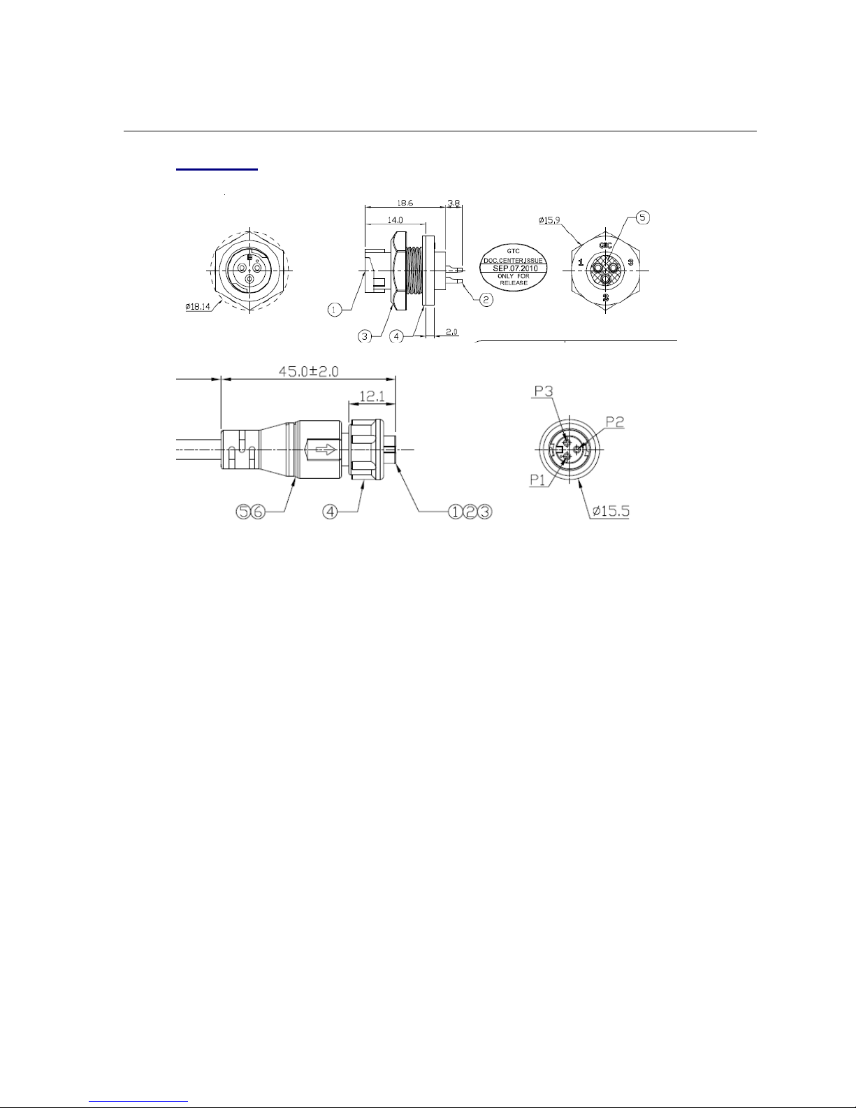
11. Mechanical
11.1. DC Input
A. Change to locking / waterproof type
Company Confidential 25 Raveon Technologies Corp.
 Loading...